EP3237683B1 - Engin de construction automoteur et procédé pour faire fonctionner un engin de construction automoteur - Google Patents
Engin de construction automoteur et procédé pour faire fonctionner un engin de construction automoteur Download PDFInfo
- Publication number
- EP3237683B1 EP3237683B1 EP15813448.6A EP15813448A EP3237683B1 EP 3237683 B1 EP3237683 B1 EP 3237683B1 EP 15813448 A EP15813448 A EP 15813448A EP 3237683 B1 EP3237683 B1 EP 3237683B1
- Authority
- EP
- European Patent Office
- Prior art keywords
- milling drum
- construction machine
- rotational speed
- operating state
- critical
- Prior art date
- Legal status (The legal status is an assumption and is not a legal conclusion. Google has not performed a legal analysis and makes no representation as to the accuracy of the status listed.)
- Revoked
Links
Images

Classifications
-
- E—FIXED CONSTRUCTIONS
- E01—CONSTRUCTION OF ROADS, RAILWAYS, OR BRIDGES
- E01C—CONSTRUCTION OF, OR SURFACES FOR, ROADS, SPORTS GROUNDS, OR THE LIKE; MACHINES OR AUXILIARY TOOLS FOR CONSTRUCTION OR REPAIR
- E01C23/00—Auxiliary devices or arrangements for constructing, repairing, reconditioning, or taking-up road or like surfaces
- E01C23/06—Devices or arrangements for working the finished surface; Devices for repairing or reconditioning the surface of damaged paving; Recycling in place or on the road
- E01C23/08—Devices or arrangements for working the finished surface; Devices for repairing or reconditioning the surface of damaged paving; Recycling in place or on the road for roughening or patterning; for removing the surface down to a predetermined depth high spots or material bonded to the surface, e.g. markings; for maintaining earth roads, clay courts or like surfaces by means of surface working tools, e.g. scarifiers, levelling blades
- E01C23/085—Devices or arrangements for working the finished surface; Devices for repairing or reconditioning the surface of damaged paving; Recycling in place or on the road for roughening or patterning; for removing the surface down to a predetermined depth high spots or material bonded to the surface, e.g. markings; for maintaining earth roads, clay courts or like surfaces by means of surface working tools, e.g. scarifiers, levelling blades using power-driven tools, e.g. vibratory tools
- E01C23/088—Rotary tools, e.g. milling drums
-
- B—PERFORMING OPERATIONS; TRANSPORTING
- B23—MACHINE TOOLS; METAL-WORKING NOT OTHERWISE PROVIDED FOR
- B23Q—DETAILS, COMPONENTS, OR ACCESSORIES FOR MACHINE TOOLS, e.g. ARRANGEMENTS FOR COPYING OR CONTROLLING; MACHINE TOOLS IN GENERAL CHARACTERISED BY THE CONSTRUCTION OF PARTICULAR DETAILS OR COMPONENTS; COMBINATIONS OR ASSOCIATIONS OF METAL-WORKING MACHINES, NOT DIRECTED TO A PARTICULAR RESULT
- B23Q17/00—Arrangements for observing, indicating or measuring on machine tools
- B23Q17/09—Arrangements for observing, indicating or measuring on machine tools for indicating or measuring cutting pressure or for determining cutting-tool condition, e.g. cutting ability, load on tool
- B23Q17/0952—Arrangements for observing, indicating or measuring on machine tools for indicating or measuring cutting pressure or for determining cutting-tool condition, e.g. cutting ability, load on tool during machining
- B23Q17/099—Arrangements for observing, indicating or measuring on machine tools for indicating or measuring cutting pressure or for determining cutting-tool condition, e.g. cutting ability, load on tool during machining by measuring features of the machined workpiece
-
- B—PERFORMING OPERATIONS; TRANSPORTING
- B28—WORKING CEMENT, CLAY, OR STONE
- B28D—WORKING STONE OR STONE-LIKE MATERIALS
- B28D1/00—Working stone or stone-like materials, e.g. brick, concrete or glass, not provided for elsewhere; Machines, devices, tools therefor
- B28D1/18—Working stone or stone-like materials, e.g. brick, concrete or glass, not provided for elsewhere; Machines, devices, tools therefor by milling, e.g. channelling by means of milling tools
-
- B—PERFORMING OPERATIONS; TRANSPORTING
- B28—WORKING CEMENT, CLAY, OR STONE
- B28D—WORKING STONE OR STONE-LIKE MATERIALS
- B28D7/00—Accessories specially adapted for use with machines or devices of the preceding groups
- B28D7/005—Devices for the automatic drive or the program control of the machines
-
- E—FIXED CONSTRUCTIONS
- E01—CONSTRUCTION OF ROADS, RAILWAYS, OR BRIDGES
- E01C—CONSTRUCTION OF, OR SURFACES FOR, ROADS, SPORTS GROUNDS, OR THE LIKE; MACHINES OR AUXILIARY TOOLS FOR CONSTRUCTION OR REPAIR
- E01C19/00—Machines, tools or auxiliary devices for preparing or distributing paving materials, for working the placed materials, or for forming, consolidating, or finishing the paving
- E01C19/004—Devices for guiding or controlling the machines along a predetermined path
-
- E—FIXED CONSTRUCTIONS
- E01—CONSTRUCTION OF ROADS, RAILWAYS, OR BRIDGES
- E01C—CONSTRUCTION OF, OR SURFACES FOR, ROADS, SPORTS GROUNDS, OR THE LIKE; MACHINES OR AUXILIARY TOOLS FOR CONSTRUCTION OR REPAIR
- E01C21/00—Apparatus or processes for surface soil stabilisation for road building or like purposes, e.g. mixing local aggregate with binder
-
- E—FIXED CONSTRUCTIONS
- E21—EARTH DRILLING; MINING
- E21C—MINING OR QUARRYING
- E21C31/00—Driving means incorporated in machines for slitting or completely freeing the mineral from the seam
- E21C31/02—Driving means incorporated in machines for slitting or completely freeing the mineral from the seam for cutting or breaking-down devices
-
- E—FIXED CONSTRUCTIONS
- E21—EARTH DRILLING; MINING
- E21C—MINING OR QUARRYING
- E21C47/00—Machines for obtaining or the removal of materials in open-pit mines
-
- B—PERFORMING OPERATIONS; TRANSPORTING
- B28—WORKING CEMENT, CLAY, OR STONE
- B28D—WORKING STONE OR STONE-LIKE MATERIALS
- B28D1/00—Working stone or stone-like materials, e.g. brick, concrete or glass, not provided for elsewhere; Machines, devices, tools therefor
- B28D1/18—Working stone or stone-like materials, e.g. brick, concrete or glass, not provided for elsewhere; Machines, devices, tools therefor by milling, e.g. channelling by means of milling tools
- B28D1/186—Tools therefor, e.g. having exchangeable cutter bits
- B28D1/188—Tools therefor, e.g. having exchangeable cutter bits with exchangeable cutter bits or cutter segments
-
- E—FIXED CONSTRUCTIONS
- E21—EARTH DRILLING; MINING
- E21C—MINING OR QUARRYING
- E21C25/00—Cutting machines, i.e. for making slits approximately parallel or perpendicular to the seam
- E21C25/06—Machines slitting solely by one or more cutting rods or cutting drums which rotate, move through the seam, and may or may not reciprocate
- E21C25/10—Rods; Drums
Definitions
- the invention relates to a self-propelled construction machine, in particular road milling machine, recycler, stabilizer or surface miner, which has a machine frame, which is supported by a chassis that has wheels or drives.
- road construction self-propelled construction machines of different types are used. These machines include the well-known road milling machines, recyclers or stabilizers. With the known road milling machines existing road layers of the road superstructure can be removed and with the known recyclers existing road surfaces can be restored. The known stabilizers are used to prepare the substructure for road construction. In addition, so-called surface miners are known as self-propelled construction machines with which coal or rock can be mined.
- the above-mentioned self-propelled construction machines have a rotating milling drum or a rotating milling / mixing rotor or a cutting roller, which are equipped with suitable milling or cutting tools.
- the milling drum, the milling / mixing rotor or the cutting roller of the known construction machines is referred to as a milling drum.
- the drive power is transmitted from the drive motor to the wheels or drives and the milling drum generally with separate drive trains, each having their own transmission systems.
- the known construction machines have a control unit with which the drive unit is controlled.
- the control unit controls the drive unit such that The construction machine can move at a certain feed rate and the milling drum can rotate at a certain speed.
- the machine operator can set the feed speed of the construction machine and the speed of the milling drum within certain limits depending on the particular working conditions.
- the speed of the milling drum is determined by the speed of the drive motor of the drive unit, so that the control of the engine speed, the Fräswalzenwindiere can be controlled.
- it may also be provided to adjust the Fräswalzenwindiere via a gear in stages or continuously, or to drive the milling drum hydraulically or electrically, whereby the Fräswalzencard can be adjusted continuously in a wide range.
- the known construction machines have an input unit. The operator can generally use the input unit to select discrete mill roll speeds that are considered appropriate for the job.
- the aim is to operate the construction machine with the highest possible feed rate, so that the performance of the construction machine is as high as possible.
- the increase of the feed speed are limited, inter alia, by the maximum power of the drive unit, which serves not only to drive the wheels or drives of the construction machine, but also to drive the milling drum.
- the fuel consumption of the internal combustion engine plays a role in the specification of the feed rate.
- the speed of the milling drum is decisive for the quality of the milling or cutting process and the wear of the milling tools of the milling drum.
- the speed of the milling drum also affects the fuel consumption and the consumption of coolant for cooling the cutting tools.
- the lowest possible speed is sought. With a low speed of the milling drum advantageously results in a lower proportion of fine grain in the milled material, whereby the dust load is reduced. At a lower speed of the milling drum, the cutting tools are subject to less wear. About that In addition, a reduction in the milling roll speed also leads to a saving of fuel and coolant. However, a reduction in the milling drum speed is limited in practice. If the speed is too low, there is the problem that the kinetic energy of the milling drum is no longer sufficient for effective processing of the material.
- All of the construction machines known in the prior art are characterized in that the feed rate of the construction machine is reduced in order to avoid a critical operating state of the milling drum due to excessive load. This unnecessarily lowers the performance of the machine if the critical operating condition could not otherwise be avoided.
- An increase in the load of the milling drum leads in the known construction machines to a reduction in the feed rate, while the rotational speed of the milling drum is maintained. In this case, the Fräswalzenfire is regularly preset too high to avoid the occurrence of critical operating conditions under all operating conditions.
- the EP 2 354 310 A2 ( US 8,128,177 B2 ) deals with the problem of undesired movement of a road milling machine by controlling the traction drive in response to reaction forces acting on the milling drum.
- various sensors are proposed, in particular sensors for measuring deformations of individual machine components, in particular the milling drum, or the pressure in the hydraulic system, for example, the hydraulic pressure in the lifting cylinders for height adjustment of the machine frame. If the measured variable detected by the sensors exceeds a critical value, the feed speed of the construction machine is reduced. The speed of the milling drum, however, is maintained.
- a road construction machine in which the feed rate is controlled in dependence on a characteristic of an operating state of the construction machine parameter, is also from the US 6,921,230 B2 known.
- the WO 03/064770 A1 describes a road milling machine having sensors for detecting an operating condition of the milling drum.
- a signal recording unit is also proposed, which detects vibrations on machine components. The vibrations of the milling drum are measured to determine the state of wear of the milling drum. It is assumed that the vibrations caused by new milling bits differ from the vibrations of worn milling tools in terms of amplitude and / or frequency.
- the invention has for its object to provide a self-propelled construction machine that can be reliably operated at different operating conditions with high efficiency.
- the inventive self-propelled construction machine in particular road milling machine, recycler, stabilizer or surface miner, has a machine frame, which is supported by a chassis that has wheels or drives. On the machine frame a milling drum is arranged.
- the wheels or drives and the milling drum are driven by a drive unit.
- the drive unit can be a device which, for example, comprises an internal combustion engine, in particular a diesel engine, and, for example, two drive trains for transmitting the drive power from the internal combustion engine to the wheels or drives and the milling drum.
- the two independent drive trains can have their own gearboxes so that the wheels or drives can be moved independently of the milling drum.
- the drive unit can also include a hydraulic transmission for driving other units of the construction machine, such as hydraulic lifting devices for height adjustment of the machine frame.
- a drive unit is also understood to mean an arrangement which comprises a plurality of drive units, for example separate drive units for the wheels or drives and the drive of the milling drum.
- the construction machine has a control unit for controlling the drive unit and a signal receiving unit for detecting at least one characteristic of an operating state of the milling drum measurement.
- the construction machine according to the invention is characterized in that the control unit is configured in such a way that the rotational speed of the milling drum is adapted to the operating conditions of the construction machine depending on at least one characteristic of a critical operating condition of the milling drum such that the milling drum is in a non-critical operating condition is operated.
- the operating conditions of the construction machine can be predetermined parameters, for example the feed rate or milling depth. These parameters can be constant during operation of the construction machine or even be changed. For adapting the Fräswalzenfitiere the feed rate of the construction machine is of particular importance.
- the feed rate to which the mill roll speed may be adjusted may be a feed rate dictated by the operator, which the operator may change during operation of the construction machine.
- the feed rate can also be specified by a control or regulating device of the construction machine. During the adjustment of the milling roll speed, the feed speed need not be constant, but may also change due to the specification by the operator or the controller. It is crucial that the feed rate is not controlled or regulated in dependence on the characteristic of the operating condition of the milling drum size, but in dependence on other variables, provided that a control or control of the feed rate at all.
- the construction machine according to the invention provides an adaptive control or regulation of Fräswalzenwidiere.
- FräswalzenFWiere To detect a critical operating state, one or more characteristic measured variables can be evaluated.
- Various evaluation algorithms can be used. For this fundamentally different functional principle of the control according to the invention, the following advantages result over the prior art.
- the adaptive control of the milling roll speed allows operation of the construction machine with respect to the milling roll speed at an optimum operating point.
- the Fräswalzenfire need not be previously adjusted to a certain value, which is considered in advance to be optimal, but is automatically adapted to the operating conditions of the construction machine, without the risk that the milling drum can get into a critical operating condition.
- the feed speed is not affected by this control, although the feed speed may also change due to other control by the operator.
- the construction machine can therefore be operated with the lowest possible milling drum speed. This results in a low wear of the milling tools and a lower fuel and coolant consumption.
- the adjustment of the milling roll speed may be made at the beginning of the milling work on the attachment of the construction machine so that the milling work is performed at the optimum milling roll speed, or may occur during the milling operations in response to changing operating conditions.
- a preferred embodiment of the invention provides that the control unit is configured in such a way that the rotational speed of the milling drum is increased when the at least one measured variable characteristic of the operating state of the milling drum exceeds a critical limit, so that the milling drum is in a non-critical operating state is operated.
- the rotational speed of the milling drum can be increased from a predetermined value stepwise or continuously until the at least one measurement variable characteristic for the operating state of the milling drum falls below the critical limit value by a predetermined tolerance value.
- the machine operator can specify with the control according to the invention before the start of the work any, lowest possible value for the Fräswalzenburniere, without having to worry about the occurrence of a critical operating condition.
- this value can also be a value already set by the controller, which need not be specified by the machine operator.
- the control according to the invention then ensures that as low as possible milling roll speed is set automatically for the milling work.
- the FräswalzenFWress is set to a value at which at least one characteristic of the operating condition of the milling drum measured value falls below the critical limit by a predetermined tolerance value. This tolerance value can also be zero.
- the critical limit can also be zero.
- the adaptation of the milling drum rotational speed can also take place in such a way that the rotational speed of the milling drum progressively increases from a too high value is continuously reduced, as long as the at least one characteristic of the operating condition of the milling drum measured value is still below a critical limit, so that the milling drum is operated, if necessary, taking into account a tolerance value in a non-critical operating condition.
- an input unit is preferably provided, with which the machine operator can select a default value, for example, under predetermined values.
- control unit is configured such that after the adaptation of the rotational speed for operating the milling drum in a non-critical operating state, the rotational speed of the milling drum is reduced and it is checked whether after reducing the rotational speed, the at least one for the Operating state of the milling drum characteristic measured value is still below the critical limit value by a predetermined tolerance value.
- the reduced speed is maintained when, after the reduction of the speed, the at least one characteristic of the operating condition of the milling drum characteristic value falls below the critical limit value by a predetermined tolerance value. Otherwise, the speed is increased again.
- the continuous adjustment of the Fräswalzenwidiere can take place at certain time intervals or after covering certain distances.
- An adaptation of the Fräswalzenwidiere can also be done at the times at which the relevant operating conditions, such as feed rate or milling depth, have changed. However, a new adaptation will not be necessary if it can be assumed that the operating conditions do not change or do not change significantly, for example, the road surface to be milled has substantially the same material properties and the feed and the milling depth remain substantially constant.
- One aspect of the invention is to intervene in the machine control during operation of the construction machine at a previously optimal operating point following a change in operating or operating conditions to restore the optimum operating point.
- the control unit preferably provides a target value control mode in which the construction machine moves at a certain feed rate and the milling drum rotates at a certain speed.
- This feed rate may be a manually given or predetermined by a controller speed, which may be constant or may also change.
- the control unit sees an adaptive control mode before, in which the construction machine moves at the feed speed and the milling drum rotates at a speed which is adapted so that the milling drum is operated in a non-critical operating state.
- the control unit is configured to transition from the setpoint control mode to the adaptive control mode in response to the at least one measurand characteristic of a critical operating condition of the milling drum. This ensures that the Fräswalzenwidiere is adjusted, regardless of a possibly already existing other control or regulation of the feed rate, when the working conditions have changed. For example, in the adaptive control mode, the milling roll speed is higher than the previously set speed when the material to be worked harder and the load of the milling drum has become larger.
- control according to the invention is basically irrelevant how the characteristic of the critical operating condition of the milling drum measured variable is detected.
- a preferred embodiment provides for detection of the critical operating state of a signal receiving unit, which has at least one sensor for detecting vibrations or shocks.
- the sensor used in this case can detect, for example, paths, speeds or accelerations. It is assumed that the milling drum in a critical operating condition is exposed to vibrations or shocks that are transmitted to the machine frame. These vibrations or shocks can basically be detected on all components of the construction machine. This includes the edge protector or the scraper of the known road milling machines, which can move up and down in a critical operating state of the milling drum jerky. Consequently, to detect the height of the edge protector or scraper, possibly existing sensors can serve as sensors for detecting vibrations or shocks. Vibrations or shocks can also be detected by deformations of the components. In this respect, sensors can also be used which detect, for example, changes in the tension of components.
- the characteristic variable which is characteristic of the critical operating state of the milling drum can be a measured variable correlated with pressure fluctuations of the hydraulic pressure in a hydraulic system of the construction machine.
- speed fluctuations of the drive motor, in particular the internal combustion engine can be detected by rotating components in the drive train of the wheels or drives and / or in the drive train of the milling drum.
- the suitable for the detection of the characteristic variable sensors are known in the art.
- accelerometers, strain gauges, pressure sensors, encoders, speed sensors, etc. can be arranged on components of the construction machine.
- the measurement signals of a plurality of identical and / or a plurality of different sensors can also be evaluated, which can be arranged on the same or different components.
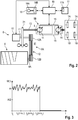
- Fig. 1 shows as an example of a self-propelled construction machine, a road milling machine for milling road surfaces made of asphalt, concrete or the like.
- the road milling machine has a machine frame 2 carried by a chassis 1.
- the chassis 1 of the milling machine comprises front and rear crawler tracks 1A, 1B, which are arranged on the working direction right and left sides of the machine frame 2. Instead of crawler wheels and wheels can be provided.
- the chain drives 1A, 1B are attached to lifting columns 3A, 3B, which are mounted on the machine frame 2, so that the machine frame is height-adjustable with respect to the ground.
- the road milling machine has a milling drum 4, which is equipped with milling tools, not shown.
- the milling drum 4 is arranged on the machine frame 2 between the front and rear crawler tracks 1A, 1B in a milling drum housing 5 which is closed at the longitudinal sides by an edge guard 6 and at the rear by a scraper, not shown.
- the milled material is removed with a conveyor 20.
- Above the Fräswalzengephinuses 5 is located on the machine frame 2, the control station 7 with a control panel 7A for the operator.
- the milling machine has a drive unit 8, which has an internal combustion engine 10.
- the internal combustion engine 10 drives, in addition to the milling drum 4, the chain drives 1A, 1B or wheels as well as further units of the milling machine.
- Fig. 2 shows the two drive trains for transmission of the drive line from the engine 10 to the drives 1A, 1B or wheels and the milling drum 4.
- the crawler tracks or wheels are only hinted at.
- Both drive trains I and II each comprise a transmission system 9A, 9B.
- the output shaft 11 of the internal combustion engine 10 is connected via a pump distributor gear 21 with a drive element 12A of a traction mechanism 12 whose output element 12B is connected to the drive shaft 4A of the milling drum 4. Consequently, the milling drum 4 is driven by the internal combustion engine 10 via the traction mechanism 12, wherein the rotational speed n of the milling drum 4 can be controlled by the rotational speed of the internal combustion engine 10. Alternatively, this can also be done via another switchable or continuously variable transmission.
- the traction drive is a hydraulic drive in the milling machine.
- the pump distributor gear 21 is connected via a shaft 13 to a hydraulic pump 14, whose volume flow is adjustable in dependence on a control signal, so that the feed speed of the construction machine can be controlled independently of the rotational speed of the drive motor.
- the hydraulic pump 14 is in turn connected via hydraulic lines 15 to a hydraulic motor 16, which drives the chain drives 1A, 1B.
- Such drive systems are known to the person skilled in the art.
- the operator can set a specific feed rate for the construction machine with an input unit 17 on the control panel 7A.
- the operator can also set a certain speed for the milling drum 4.
- the operator can select certain milling roll speeds n 1 , n 2 , n 3, etc.
- the control of the drive unit 8 in addition to the mode of operation in which the rotational speed of the milling drum can be freely set, also provides an operating mode in which the milling drum rotational speed is automatically adjusted to the different working conditions of the construction machine. This adaptive mode of operation may be selected on the input unit 17.
- the construction machine has a signal recording unit 18 for detecting at least one characteristic variable for the operating state of the milling drum 4.
- the signal recording unit 18 has at least one sensor 18A, which in Fig. 2 is exemplified only schematically for all sensors.
- the sensor 18A is an accelerometer that detects vibrations or shocks.
- the sensor can be arranged on a component of the construction machine, to which the vibrations or shocks which occur during a critical operating state of the milling drum 4, ie when the milling drum is operated at too low a milling roll speed.
- the accelerometer 18A is fixed to the machine frame 2.
- the acceleration sensor 18A can also be arranged on the milling drum or the milling drum housing.
- the filter unit 18B is designed in such a way that the interference signals, which differ in amplitude and / or frequency from the characteristic measured variable, are filtered out.
- the strain sensor is attached to the milling drum 4. But it can also be provided at least one accelerometer and a strain sensor, which is closed to an unstable operating condition when vibrations or shocks and / or detected with the strain sensor deformations with the accelerometer.
- the control unit 19 for the drive unit 8 has a data processing unit (microprocessor) on which a data processing program (software) runs, so that the method steps described below are carried out.
- a data processing unit microprocessor
- a data processing program software
- the machine operator specifies a feed rate for the construction machine before starting the milling work.
- the control unit 19 controls the drive unit 8 such that the construction machine moves at the predetermined feed speed v and the milling drum 4 rotates at a certain speed n.
- the fixed predetermined by the control unit 19 Fräswalzennaviere, which could also be freely specified by the operator, in the present embodiment is below the speed required for a non-critical operating condition.
- the sensor 18A of the signal receiving unit 18 detects vibrations or shocks that occur at too low Fräswalzenwindiere.
- This characteristic measured variable M (t) is evaluated in the control unit 19.
- the control unit 19 increases the speed of the milling drum 4 from the predetermined value stepwise or continuously until the characteristic measured variable falls below a critical limit value by a predetermined tolerance value.
- Fig. 3 an embodiment described in which it is assumed that the average value of the characteristic measured variable at a critical operating condition A and in an uncritical operating condition is ideally 0, but may also be greater than 0, wherein the transition from a critical to a non-critical state abruptly is, that is, the measured variable drops abruptly to zero or a value considered to be uncritical value greater than zero.
- the characteristic measurand M (t) is in Fig.
- the critical limit value is assumed to be less than A, for example A / 2.
- the rotational speed n of the milling drum is incrementally increased from the predetermined value n 1 , n 2 , n 3 ... N n or continuously.
- the speed has reached a value n 3 at which the characteristic measured variable is 0, ie the characteristic measured variable has fallen below the limit value A / 2 by a predetermined tolerance value (A / 2).
- the operating state is stable.
- An uncritical operating state can also be assumed if the measured variable is greater than 0, but less than the critical limit, for example A / 8.
- the tolerance value may be, for example, A / 4.
- the transition from the critical to the uncritical state can also be continuous.
- the control unit 19 now sets the speed n 3 as a set speed for the milling drum. This is the optimal operating point.
- the transition from a critical to a non-critical operating state or vice versa is erratic. But it is also possible that this transition is continuous. Then, the average value A of the characteristic quantity M (t) in a transition region from an unstable to a stable state will decrease continuously.
- the milling roll rotational speed can be determined at which a sufficiently stable state can be assumed, ie. H. the characteristic measured variable has a sufficient distance from the critical limit value.
- This milling roll speed can basically be maintained for the work project if it is assumed that the working conditions remain unchanged, for example, the material properties of the soil material do not change and also the depth of cut or the feed is not changed. Otherwise, a correction of Fräswalenfire may be required.
- the control unit 19 successively reduces the milling drum rotational speed and in each case checks whether, after the reduction of the rotational speed, the at least one characteristic variable M (t) characteristic of the operating state of the milling drum falls below the critical limit value by a predetermined tolerance value. The reduced speed is then maintained as the adjusted or corrected target speed when the above condition exists. Otherwise, the speed is increased again.
- the reduction of the Fräswalzennaviere for example, after a predetermined time interval or after covering a predetermined Distance gradually or continuously.
- the milling drum speed can also be adapted to the changed parameters after changing other parameters, eg. B. to a modified feed rate or milling depth.
- the feed rate is not predetermined by the operator, but by a control or regulating device, which may be part of the control unit 19.
- This control or regulation of the feed rate which can be done by the known methods, but does not take place in dependence on the characteristic of the critical operating condition of the milling drum size.
- the inventive adaptation of the Fräswalzenwidiere then takes place independently of this control or regulation.
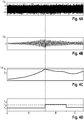
- FIGS. 4A to 4D Another embodiment is described in which an upper and lower limit value for the effective value of the characteristic measurand M (t) is determined.
- Fig. 4A shows the noisy output of sensor 18A, such as an acceleration sensor, as a function of time.
- the characteristic measurand M (t) is superposed in the output signal of the sensor 18A by various disturbance variables.
- the filter unit 18B has a band-pass filter which allows only signals in a frequency band of, for example, 0.25 to 20 Hz, in particular 0.5 to 10 Hz, to pass.
- Fig. 4B shows the noise-removed output of the bandpass filter.
- the filter unit 18B further comprises a unit for determining the effective value of the output signal of the bandpass filter.
- the rms value of the output signal of the bandpass filter represents the characteristic measurand M (t) ( Fig. 4C ).
- the milling drum 4 rotates in the time interval A first with a predetermined speed n 1 ( Fig. 4D ). It turns out that the measured quantity M (t) increases continuously in the time interval A, which indicates the occurrence of an unstable state ( Fig. 4C ).
- the increase in the measured quantity M (t) may be due to changing working conditions, for example a change in the nature of the road surface to be scoured off.
- the measured variable M (t) can also be due to an increase in the Feed rate in the time interval A, which is specified by another controller or control, which is not based on the monitoring of the measured variable M (t).
- the rotational speed n of the milling drum 4 in the present exemplary embodiment is increased stepwise from n 1 to n 2 in order to produce a second critical value S 1 not to produce critical operating condition of the milling drum. It can be seen that the measured variable M (t) falls below the upper critical limit value due to the speed increase.
- the milling drum 4 is now operated in the time interval B with the increased speed n 2 , wherein the measured variable M (t) decreases continuously. In this embodiment, however, the measurand M (t) does not abruptly drop to zero as in the embodiment of FIG Fig.
- Fig. 4C shows the case that an increase of the Fräswalzenfitiere n from n 1 to n 2 is sufficient. It can be seen that the measured quantity M (t) decreases after the adaptation of the milling drum rotational speed n until it has reached or fallen below a lower limit value S 2 , which is regarded as uncritical. If the Fräswalzenwidiere has reached or fallen below the lower limit value S 2 , the speed n of the milling drum 4 is again reduced to the value n 1 . In the subsequent time interval C, the milling drum rotational speed n 1 is maintained, with the measured variable M (t) again rising slowly, but still remaining below the upper critical limit value S 1 . Consequently, an upper or lower switching point for a sudden or continuous speed increase or speed reduction is set within a predetermined tolerance range.
- a particular aspect of the invention is that the control of the drive unit of the construction machine provides a target value control mode in which the construction machine can be operated for certain working conditions in an optimal operating point.
- the construction machine moves at a certain feed rate, which can be set by the operator or a controller, and the milling drum 4 rotates at a certain speed.
- the construction machine may transition to an adaptive control mode in which the construction machine moves at the feed rate and the speed of the milling drum 4 is adjusted such that the milling drum is operated in a non-critical operating condition.
- the feed speed of the construction machine is not affected by this control.
- the control of the drive unit 8 envisages transitioning from the setpoint control mode into the adaptive control mode as a function of the measured variable M (t) which is characteristic for a critical operating state of the milling drum 4. This ensures that even with changing working conditions a critical operating condition for the milling drum can not occur.
- the construction machine enters the adaptive control mode in which the construction machine is operated at a higher rotational speed than the predetermined softer material speed at the same feed rate , As the material softens again, the construction machine may return to the setpoint control mode.
Claims (17)
- Engin de construction automoteur, en particulier fraiseuse routière, recycleur, stabilisateur ou mineur de surface, avec
un bâti de machine (2), qui est supporté par un châssis (1), qui présente des roues ou des mécanismes de roulement (1A, 1B),
un cylindre de fraisage (4) disposé au niveau du bâti de machine (2),
une unité d'entraînement (8) servant à entraîner les roues ou les mécanismes de roulement (1A, 1B) et le cylindre de fraisage (4),
une unité de commande (19) servant à commander l'unité d'entraînement (8),
une unité de réception de signal (18) servant à détecter au moins une grandeur de mesure (M(t)) caractéristique d'un état de fonctionnement du cylindre de fraisage, caractérisé en ce que l'unité de commande (19) est configurée de telle manière que le nombre de tours du cylindre de fraisage (4) est adapté aux conditions de fonctionnement de l'engin de construction en fonction d'au moins une grandeur de mesure (M(t)) caractéristique d'un état de fonctionnement critique du cylindre de fraisage de telle manière que le cylindre de fraisage fonctionne dans un état de fonctionnement non critique. - Engin de construction automoteur selon la revendication 1, caractérisé en ce que l'unité de commande (19) est configurée de telle manière que le nombre de tours du cylindre de fraisage est augmenté quand l'au moins une grandeur de mesure (M(t)) caractéristique de l'état de fonctionnement du cylindre de fraisage dépasse une valeur limite critique, de sorte que le cylindre de fraisage (4) fonctionne dans un état de fonctionnement non critique.
- Engin de construction automoteur selon la revendication 1 ou 2, caractérisé en ce que l'unité de commande (19) est configurée de telle manière que le nombre de tours du cylindre de fraisage (4) est augmenté d'une valeur spécifiée progressivement jusqu'à ce que l'au moins une grandeur de mesure (M(t)) caractéristique de l'état de fonctionnement du cylindre de fraisage présente une valeur inférieure à la valeur limite critique d'une valeur de tolérance spécifiée ou le nombre de tours du cylindre de fraisage est augmenté en continu d'une valeur spécifiée jusqu'à ce que l'au moins une grandeur de mesure (M(t)) caractéristique de l'état de fonctionnement du cylindre de fraisage présente une valeur inférieure à la valeur limite critique d'une valeur de tolérance spécifiée.
- Engin de construction automoteur selon la revendication 3, caractérisé en ce que l'engin de construction présente une unité de saisie (17) servant à saisir la valeur spécifiée pour le nombre de tours du cylindre de fraisage (4).
- Engin de construction automoteur selon l'une quelconque des revendications 1 à 4, caractérisé en ce que l'unité de commande (19) est configurée de telle manière qu'après l'adaptation du nombre de tours du cylindre de fraisage (4) pour faire fonctionner le cylindre de fraisage dans un état non critique, le nombre de tours du cylindre de fraisage est réduit et il est vérifié si après la réduction du nombre de tours, l'au moins une grandeur de mesure (M(t)) caractéristique de l'état de fonctionnement du cylindre de fraisage présente une valeur inférieure à la valeur limite critique d'une valeur de tolérance spécifiée, dans lequel le nombre de tours réduit est conservé si après la réduction du nombre de tours, l'au moins une grandeur de mesure caractéristique de l'état de fonctionnement du cylindre de fraisage présente une valeur inférieure à la valeur limite critique d'une valeur de tolérance spécifiée.
- Engin de construction automoteur selon l'une quelconque des revendications 1 à 5, caractérisé en ce que l'unité de commande (19) prévoit un mode de commande de valeur de consigne, dans lequel l'engin de construction se déplace à une vitesse d'avance définie et le cylindre de fraisage (4) tourne avec un nombre de tours défini, et prévoit un mode de commande adaptatif, dans lequel l'engin de construction se déplace à la vitesse d'avance et le cylindre de fraisage tourne avec un nombre de tours, qui est adapté de telle manière que le cylindre de fraisage (4) fonctionne dans un état de fonctionnement non critique, dans lequel l'unité de commande (19) passe du mode de commande de valeur de consigne dans le mode de commande adaptatif en fonction de l'au moins une grandeur de mesure caractéristique d'un état de fonctionnement critique du cylindre de fraisage (4).
- Engin de construction automoteur selon l'une quelconque des revendications 1 à 6, caractérisé en ce que l'unité de réception de signal (18) présente au moins un capteur (18A) servant à détecter des vibrations ou des à-coups, qui apparaissent lors du fonctionnement du cylindre de fraisage dans un état de fonctionnement critique.
- Engin de construction automoteur selon la revendication 7, caractérisé en ce que le capteur (18A) servant à détecter des vibrations ou des à-coups est une sonde d'accélération ou un capteur de contrainte disposée ou disposé au niveau d'un composant de l'engin de construction.
- Engin de construction automoteur selon la revendication 7 ou 8, caractérisé en ce que le capteur (18A) servant à détecter des vibrations ou des à-coups est disposé au niveau du cylindre de fraisage (4), du boîtier de cylindre de fraisage (5) ou du bâti de machine (2) de l'engin de construction.
- Engin de construction automoteur selon l'une quelconque des revendications 1 à 6, caractérisé en ce que l'unité de réception de signal (18) présente au moins un capteur de pression disposé dans un système hydraulique de l'engin de construction, servant à mesurer des fluctuations de la pression hydraulique.
- Engin de construction automoteur selon l'une quelconque des revendications 1 à 6, caractérisé en ce que l'unité de réception de signal (18) est réalisée de telle manière que des fluctuations de nombre de tours de composants en rotation dans la chaîne cinématique des roues ou des mécanismes de roulement et/ou dans la chaîne cinématique du cylindre de fraisage sont détectées.
- Procédé servant à faire fonctionner un engin de construction automoteur, en particulier une fraiseuse routière, un recycleur, un stabilisateur ou un mineur de surface, qui présente :un bâti de machine (2), qui est supporté par un châssis (1), qui présente des roues ou des mécanismes de roulement,un cylindre de fraisage (4) disposé au niveau du bâti de machine (2),caractérisé en ce que le nombre de tours du cylindre de fraisage (4) est adapté aux conditions de fonctionnement de l'engin de construction en fonction d'au moins une grandeur de mesure (M(t)) caractéristique d'un état de fonctionnement critique du cylindre de fraisage de telle manière que le cylindre de fraisage fonctionne dans un état de fonctionnement non critique.
- Procédé selon la revendication 12, caractérisé en ce que le nombre de tours du cylindre de fraisage (4) est augmenté quand l'au moins une grandeur de mesure (M(t)) caractéristique de l'état de fonctionnement du cylindre de fraisage dépasse une valeur limite critique de sorte que le cylindre de fraisage fonctionne dans un état de fonctionnement non critique.
- Procédé selon la revendication 12 ou 13, caractérisé en ce que le nombre de tours du cylindre de fraisage (4) est augmenté progressivement d'une valeur spécifiée jusqu'à ce que l'au moins une grandeur de mesure (M(t)) caractéristique de l'état de fonctionnement du cylindre de fraisage présente une valeur inférieure à la valeur limite critique d'une valeur de tolérance spécifiée ou le nombre de tours du cylindre de fraisage (4) est augmenté en continu d'une valeur spécifiée jusqu'à ce que l'au moins une grandeur de mesure (M(t)) caractéristique de l'état de fonctionnement du cylindre de fraisage présente une valeur inférieure à la valeur limite critique d'une valeur de tolérance spécifiée.
- Procédé selon l'une quelconque des revendications 12 à 14, caractérisé en ce qu'après l'adaptation du nombre de tours du cylindre de fraisage (4) pour faire fonctionner le cylindre de fraisage dans un état non critique, le nombre de tours du cylindre de fraisage est réduit et il est vérifié si après la réduction du nombre de tours, l'au moins une grandeur de mesure (M(t)) caractéristique de l'état de fonctionnement du cylindre de fraisage présente une valeur inférieure à la valeur limite critique d'une valeur de tolérance spécifiée, dans lequel le nombre de tours réduit est conservé si après la réduction du nombre de tours, l'au moins une grandeur de mesure (M(t)) caractéristique de l'état de fonctionnement du cylindre de fraisage présente une valeur inférieure à la valeur limite critique d'une valeur de tolérance spécifiée.
- Procédé selon l'une quelconque des revendications 12 à 15, caractérisé en ce que l'engin de construction peut fonctionner dans un mode de commande de valeur de consigne, dans lequel l'engin de construction se déplace à une vitesse d'avance définie et le cylindre de fraisage (4) tourne avec un nombre de tours défini, et peut fonctionner dans un mode de commande adaptatif, dans lequel l'engin de construction se déplace à la vitesse d'avance et le cylindre de fraisage (4) tourne avec un nombre de tours, qui est adapté de telle manière que le cylindre de fraisage (4) fonctionne dans un état de fonctionnement non critique, dans lequel on passe du mode de commande de valeur de consigne dans le mode de commande adaptatif en fonction de l'au moins une grandeur de mesure (M(t)) caractéristique d'un état de fonctionnement critique du cylindre de fraisage.
- Procédé selon l'une quelconque des revendications 12 à 16, caractérisé en ce que la grandeur de mesure (M(t)) caractéristique de l'état de fonctionnement critique du cylindre de fraisage est une grandeur de mesure en corrélation avec des vibrations ou des à-coups, qui apparaissent lors du fonctionnement du cylindre de fraisage (4) dans un état de fonctionnement critique au niveau d'un composant de l'engin de construction, ou est une grandeur de mesure en corrélation avec des fluctuations de nombre de tours de composants en rotation dans la chaîne cinématique des roues ou des mécanismes de roulement ou dans la chaîne cinématique du cylindre de fraisage ou est une grandeur de mesure en corrélation avec des fluctuations de la pression hydraulique dans un système hydraulique de l'engin de construction.
Priority Applications (1)
| Application Number | Priority Date | Filing Date | Title |
|---|---|---|---|
| EP18208011.9A EP3483341B1 (fr) | 2014-12-23 | 2015-12-20 | Engin de chantier automoteur et procédé de fonctionnement d'un engin de chantier automoteur |
Applications Claiming Priority (3)
| Application Number | Priority Date | Filing Date | Title |
|---|---|---|---|
| DE102014019277 | 2014-12-23 | ||
| DE102015002743.3A DE102015002743A1 (de) | 2014-12-23 | 2015-03-05 | Selbstfahrende Baumaschine und Verfahren zum Betreiben einer selbstfahrenden Baumaschine |
| PCT/EP2015/080699 WO2016102410A1 (fr) | 2014-12-23 | 2015-12-20 | Engin de construction automoteur et procédé pour faire fonctionner un engin de construction automoteur |
Related Child Applications (1)
| Application Number | Title | Priority Date | Filing Date |
|---|---|---|---|
| EP18208011.9A Division EP3483341B1 (fr) | 2014-12-23 | 2015-12-20 | Engin de chantier automoteur et procédé de fonctionnement d'un engin de chantier automoteur |
Publications (2)
| Publication Number | Publication Date |
|---|---|
| EP3237683A1 EP3237683A1 (fr) | 2017-11-01 |
| EP3237683B1 true EP3237683B1 (fr) | 2018-12-05 |
Family
ID=56097887
Family Applications (2)
| Application Number | Title | Priority Date | Filing Date |
|---|---|---|---|
| EP18208011.9A Active EP3483341B1 (fr) | 2014-12-23 | 2015-12-20 | Engin de chantier automoteur et procédé de fonctionnement d'un engin de chantier automoteur |
| EP15813448.6A Revoked EP3237683B1 (fr) | 2014-12-23 | 2015-12-20 | Engin de construction automoteur et procédé pour faire fonctionner un engin de construction automoteur |
Family Applications Before (1)
| Application Number | Title | Priority Date | Filing Date |
|---|---|---|---|
| EP18208011.9A Active EP3483341B1 (fr) | 2014-12-23 | 2015-12-20 | Engin de chantier automoteur et procédé de fonctionnement d'un engin de chantier automoteur |
Country Status (5)
| Country | Link |
|---|---|
| US (3) | US10358780B2 (fr) |
| EP (2) | EP3483341B1 (fr) |
| CN (1) | CN107109809B (fr) |
| DE (1) | DE102015002743A1 (fr) |
| WO (1) | WO2016102410A1 (fr) |
Cited By (1)
| Publication number | Priority date | Publication date | Assignee | Title |
|---|---|---|---|---|
| EP3483341A1 (fr) | 2014-12-23 | 2019-05-15 | Wirtgen GmbH | Engin de chantier automoteur et procédé de fonctionnement d'un engin de chantier automoteur |
Families Citing this family (7)
| Publication number | Priority date | Publication date | Assignee | Title |
|---|---|---|---|---|
| DE102015014573B4 (de) | 2015-11-12 | 2020-03-19 | Wirtgen Gmbh | Selbstfahrende Bodenfräsmaschine und Verfahren zum Bearbeiten einer Verkehrsfläche |
| DE102016216216A1 (de) | 2016-08-29 | 2018-03-01 | Wirtgen Gmbh | Verfahren zum Bearbeiten von Bodenbelägen, sowie selbstfahrende Baumaschine |
| DE102016010390A1 (de) | 2016-08-30 | 2018-03-01 | Wirtgen Gmbh | Fräsmaschine und Verfahren zum Betrieb einer Fräsmaschine |
| DE102019210644A1 (de) * | 2019-07-18 | 2021-01-21 | Wirtgen Gmbh | Selbstfahrende Baumaschine und Verfahren zum Bearbeiten von Bodenbelägen |
| DE102019135668A1 (de) * | 2019-12-23 | 2021-06-24 | Wirtgen Gmbh | Selbstfahrende Baumaschine und Verfahren zum Steuern einer selbstfahrenden Baumaschine |
| US11891762B2 (en) * | 2021-12-07 | 2024-02-06 | Caterpillar Paving Products Inc. | Systems and methods for controlling operation of a milling machine based on vibration |
| DE102022122472B4 (de) | 2022-09-05 | 2024-03-28 | Wirtgen Gmbh | Selbstfahrende Bodenbearbeitungsmaschine mit Zwillingsmotoren und einem deren Leistung unterschiedlich übertragenden Arbeitsgetriebe |
Family Cites Families (22)
| Publication number | Priority date | Publication date | Assignee | Title |
|---|---|---|---|---|
| US5318378A (en) | 1992-09-28 | 1994-06-07 | Caterpillar Paving Products Inc. | Method and apparatus for controlling a cold planer in response to a kickback event |
| US5879056A (en) * | 1997-04-25 | 1999-03-09 | Caterpillar Inc. | Kickback protection device and method of use |
| US6210071B1 (en) * | 1999-09-27 | 2001-04-03 | Astec Industries, Inc. | Method and apparatus for cutting rumble strips in a roadway |
| DE10203732A1 (de) | 2002-01-30 | 2003-08-21 | Wirtgen Gmbh | Baumaschine |
| DE10213017A1 (de) | 2002-03-22 | 2003-10-09 | Wirtgen Gmbh | Verfahren zum Optimieren eines Schneidprozesses bei Straßenfräsmaschinen, sowie Fräsmaschine zum Bearbeiten von Straßendecken |
| US6921230B2 (en) | 2002-12-24 | 2005-07-26 | Diamond Products, Limited | Closed loop control system for pavement surfacing machine |
| US8465105B2 (en) | 2007-01-18 | 2013-06-18 | Cmi Terex Corporation | Control system for cutter drum |
| WO2008115560A1 (fr) * | 2007-03-20 | 2008-09-25 | Volvo Construction Equipment Ab | Fraiseuse avec commande de vitesse de tambour porte-couteaux |
| US8061782B2 (en) | 2008-09-12 | 2011-11-22 | Hall David R | Sensors on a degradation machine |
| US8128177B2 (en) | 2010-02-08 | 2012-03-06 | Wirtgen Gmbh | Adaptive advance drive control for milling machine |
| DE102010014644B4 (de) * | 2010-04-12 | 2021-07-22 | Liebherr-Components Biberach Gmbh | Selbstfahrende Arbeitsmaschine mit elektrischem Antriebssystem sowie Verfahren zum Betreiben einer solchen |
| DE102010014893A1 (de) | 2010-04-14 | 2011-10-20 | Bomag Gmbh | Vorrichtung zum Bearbeiten von Bodenoberflächen |
| DE102010014903A1 (de) | 2010-04-14 | 2011-10-20 | Bomag Gmbh | Überwachungsvorrichtung für eine Bodenfräsmaschine |
| DE102010015173A1 (de) * | 2010-04-16 | 2011-10-20 | Bomag Gmbh | Verfahren zum Betrieb einer Bodenfräsmaschine mit höhenverstellbarer Fräswalze |
| DE102011053984A1 (de) | 2011-09-27 | 2013-03-28 | Caterpillar Global Mining Europe Gmbh | Vorrichtung für die fräsende und/oder bohrende Bearbeitung von Materialien und Verfahren hierfür |
| DE102011116268A1 (de) | 2011-10-19 | 2013-04-25 | Wirtgen Gmbh | Selbstfahrende Baumaschine |
| DE102012006189A1 (de) | 2012-03-27 | 2013-10-02 | Bomag Gmbh | Antriebsvorrichtung in einer selbstfahrenden Baumaschine sowie Verfahren zum Einstellen eines Drehzahlverhältnisses bei einer derartigen Antriebsvorrichtung |
| US8794869B2 (en) | 2012-04-30 | 2014-08-05 | Caterpillar Paving Products Inc. | Rotary mixer and method for controlling material gradation thereof |
| US9121146B2 (en) * | 2012-10-08 | 2015-09-01 | Wirtgen Gmbh | Determining milled volume or milled area of a milled surface |
| DE102014001885A1 (de) * | 2014-02-12 | 2015-08-13 | Bomag Gmbh | Verfahren zur Optimierung einer Betriebsfunktion einer Bodenfräsmaschine und Bodenfräsmaschine |
| DE102015002743A1 (de) | 2014-12-23 | 2016-06-23 | Wirtgen Gmbh | Selbstfahrende Baumaschine und Verfahren zum Betreiben einer selbstfahrenden Baumaschine |
| DE102015209740A1 (de) * | 2014-12-30 | 2016-06-30 | Wirtgen Gmbh | Selbstfahrende Strassenfräsmaschine zum Bearbeiten von Strassenoberflächen, sowie Verfahren zum Bearbeiten von Strassenoberflächen mit einer Strassenfräsmaschine |
-
2015
- 2015-03-05 DE DE102015002743.3A patent/DE102015002743A1/de active Pending
- 2015-12-20 CN CN201580070469.5A patent/CN107109809B/zh active Active
- 2015-12-20 EP EP18208011.9A patent/EP3483341B1/fr active Active
- 2015-12-20 EP EP15813448.6A patent/EP3237683B1/fr not_active Revoked
- 2015-12-20 WO PCT/EP2015/080699 patent/WO2016102410A1/fr active Application Filing
- 2015-12-20 US US15/534,812 patent/US10358780B2/en active Active
-
2019
- 2019-07-02 US US16/460,108 patent/US11015304B2/en active Active
-
2021
- 2021-05-18 US US17/322,959 patent/US11603631B2/en active Active
Non-Patent Citations (1)
| Title |
|---|
| None * |
Cited By (1)
| Publication number | Priority date | Publication date | Assignee | Title |
|---|---|---|---|---|
| EP3483341A1 (fr) | 2014-12-23 | 2019-05-15 | Wirtgen GmbH | Engin de chantier automoteur et procédé de fonctionnement d'un engin de chantier automoteur |
Also Published As
| Publication number | Publication date |
|---|---|
| US11015304B2 (en) | 2021-05-25 |
| WO2016102410A1 (fr) | 2016-06-30 |
| US11603631B2 (en) | 2023-03-14 |
| US20170356142A1 (en) | 2017-12-14 |
| DE102015002743A1 (de) | 2016-06-23 |
| CN107109809B (zh) | 2019-04-02 |
| US20200002904A1 (en) | 2020-01-02 |
| EP3237683A1 (fr) | 2017-11-01 |
| CN107109809A (zh) | 2017-08-29 |
| US10358780B2 (en) | 2019-07-23 |
| EP3483341A1 (fr) | 2019-05-15 |
| EP3483341B1 (fr) | 2024-04-24 |
| US20210332536A1 (en) | 2021-10-28 |
Similar Documents
| Publication | Publication Date | Title |
|---|---|---|
| EP3237683B1 (fr) | Engin de construction automoteur et procédé pour faire fonctionner un engin de construction automoteur | |
| EP2584095B1 (fr) | Engin automobile et procédé de contrôle d'un tel engin | |
| EP1293697B1 (fr) | Procédure et dispositif de commande d'embrayage | |
| EP3290586B1 (fr) | Fraiseuse et procédé de fonctionnement d'une fraiseuse | |
| EP3168367B1 (fr) | Fraiseuse autotractée et procédé de traitement des surfaces routières | |
| DE102017010919B4 (de) | Verfahren zum Steuern einer Höhenverstellung eines Abstreifschildes einer Bodenfräsmaschine und Bodenfräsmaschine | |
| DE112008000646T5 (de) | Fräsmaschine mit Schneidtrommel-Geschwindigkeitssteuerung | |
| DE102014019168A1 (de) | BAUMASCHINE, INSBESONDERE STRAßENFRÄSE, UND VERFAHREN ZUM AUSGLEICHEN VON BODENUNEBENHEITEN FÜR EINE SOLCHE BAUMASCHINE | |
| EP3587668B1 (fr) | Engin de construction automoteur et procédé de traitement des revêtements de sol | |
| EP2558645B1 (fr) | Procédé pour faire fonctionner une fraiseuse à découper les sols munie d'un cylindre de fraisage réglable en hauteur | |
| EP3208382B1 (fr) | Engin automobile et procédé de fonctionnement d'un engin automobile | |
| DE10203732A1 (de) | Baumaschine | |
| EP3549433A1 (fr) | Système de commande de hauteur pour un appareil tête de récolte | |
| WO2008077963A1 (fr) | Fraiseuse routière et procédé permettant d'obtenir le parallélisme du bâti de machine par rapport au sol | |
| DE2503340B2 (de) | Verfahren und Vorrichtung zur Antriebssteuerung von Bohrköpfen, insbesondere für Großlochbohrmaschinen | |
| DE102017012124A1 (de) | Verfahren zur Steuerung der Höhenlage eines Niederhalters einer Bodenfräsmaschine und Bodenfräsmaschine | |
| EP2832205B2 (fr) | Moissonneuse automotrice | |
| DE102005020170A1 (de) | Hobeleinrichtung und Verfahren zum Ansteuern einer Hobeleinrichtung | |
| EP3767033B1 (fr) | Engin de construction automoteur et procédé de traitement des revêtements de sol | |
| WO2021089603A1 (fr) | Procédé et dispositif de coupe de tranchée destinés à la création d'une tranchée dans le sol | |
| DE102016002294A1 (de) | Bodenfräsmaschine, Verfahren zum Steuern einer Sicherheitsabschalteinrichtung einer Fräswalze einer Bodenfräsmaschine und Steuereinheit | |
| WO2020048629A1 (fr) | Système hydraulique comprenant un moteur hydraulique, procédé de fonctionnement et engin de travail équipé d'un système hydraulique de ce type |
Legal Events
| Date | Code | Title | Description |
|---|---|---|---|
| STAA | Information on the status of an ep patent application or granted ep patent |
Free format text: STATUS: THE INTERNATIONAL PUBLICATION HAS BEEN MADE |
|
| PUAI | Public reference made under article 153(3) epc to a published international application that has entered the european phase |
Free format text: ORIGINAL CODE: 0009012 |
|
| STAA | Information on the status of an ep patent application or granted ep patent |
Free format text: STATUS: REQUEST FOR EXAMINATION WAS MADE |
|
| 17P | Request for examination filed |
Effective date: 20170718 |
|
| AK | Designated contracting states |
Kind code of ref document: A1 Designated state(s): AL AT BE BG CH CY CZ DE DK EE ES FI FR GB GR HR HU IE IS IT LI LT LU LV MC MK MT NL NO PL PT RO RS SE SI SK SM TR |
|
| AX | Request for extension of the european patent |
Extension state: BA ME |
|
| DAV | Request for validation of the european patent (deleted) | ||
| DAX | Request for extension of the european patent (deleted) | ||
| REG | Reference to a national code |
Ref country code: DE Ref legal event code: R079 Ref document number: 502015007150 Country of ref document: DE Free format text: PREVIOUS MAIN CLASS: E01C0023088000 Ipc: B28D0001180000 |
|
| GRAP | Despatch of communication of intention to grant a patent |
Free format text: ORIGINAL CODE: EPIDOSNIGR1 |
|
| STAA | Information on the status of an ep patent application or granted ep patent |
Free format text: STATUS: GRANT OF PATENT IS INTENDED |
|
| RIC1 | Information provided on ipc code assigned before grant |
Ipc: B28D 1/18 20060101AFI20180518BHEP Ipc: E01C 23/088 20060101ALI20180518BHEP |
|
| INTG | Intention to grant announced |
Effective date: 20180607 |
|
| GRAS | Grant fee paid |
Free format text: ORIGINAL CODE: EPIDOSNIGR3 |
|
| GRAA | (expected) grant |
Free format text: ORIGINAL CODE: 0009210 |
|
| STAA | Information on the status of an ep patent application or granted ep patent |
Free format text: STATUS: THE PATENT HAS BEEN GRANTED |
|
| AK | Designated contracting states |
Kind code of ref document: B1 Designated state(s): AL AT BE BG CH CY CZ DE DK EE ES FI FR GB GR HR HU IE IS IT LI LT LU LV MC MK MT NL NO PL PT RO RS SE SI SK SM TR |
|
| REG | Reference to a national code |
Ref country code: GB Ref legal event code: FG4D Free format text: NOT ENGLISH |
|
| REG | Reference to a national code |
Ref country code: CH Ref legal event code: EP |
|
| REG | Reference to a national code |
Ref country code: AT Ref legal event code: REF Ref document number: 1072469 Country of ref document: AT Kind code of ref document: T Effective date: 20181215 |
|
| REG | Reference to a national code |
Ref country code: IE Ref legal event code: FG4D Free format text: LANGUAGE OF EP DOCUMENT: GERMAN |
|
| REG | Reference to a national code |
Ref country code: DE Ref legal event code: R096 Ref document number: 502015007150 Country of ref document: DE |
|
| REG | Reference to a national code |
Ref country code: SE Ref legal event code: TRGR |
|
| REG | Reference to a national code |
Ref country code: NL Ref legal event code: MP Effective date: 20181205 |
|
| REG | Reference to a national code |
Ref country code: LT Ref legal event code: MG4D |
|
| PG25 | Lapsed in a contracting state [announced via postgrant information from national office to epo] |
Ref country code: FI Free format text: LAPSE BECAUSE OF FAILURE TO SUBMIT A TRANSLATION OF THE DESCRIPTION OR TO PAY THE FEE WITHIN THE PRESCRIBED TIME-LIMIT Effective date: 20181205 Ref country code: BG Free format text: LAPSE BECAUSE OF FAILURE TO SUBMIT A TRANSLATION OF THE DESCRIPTION OR TO PAY THE FEE WITHIN THE PRESCRIBED TIME-LIMIT Effective date: 20190305 Ref country code: HR Free format text: LAPSE BECAUSE OF FAILURE TO SUBMIT A TRANSLATION OF THE DESCRIPTION OR TO PAY THE FEE WITHIN THE PRESCRIBED TIME-LIMIT Effective date: 20181205 Ref country code: LV Free format text: LAPSE BECAUSE OF FAILURE TO SUBMIT A TRANSLATION OF THE DESCRIPTION OR TO PAY THE FEE WITHIN THE PRESCRIBED TIME-LIMIT Effective date: 20181205 Ref country code: LT Free format text: LAPSE BECAUSE OF FAILURE TO SUBMIT A TRANSLATION OF THE DESCRIPTION OR TO PAY THE FEE WITHIN THE PRESCRIBED TIME-LIMIT Effective date: 20181205 Ref country code: NO Free format text: LAPSE BECAUSE OF FAILURE TO SUBMIT A TRANSLATION OF THE DESCRIPTION OR TO PAY THE FEE WITHIN THE PRESCRIBED TIME-LIMIT Effective date: 20190305 |
|
| PG25 | Lapsed in a contracting state [announced via postgrant information from national office to epo] |
Ref country code: RS Free format text: LAPSE BECAUSE OF FAILURE TO SUBMIT A TRANSLATION OF THE DESCRIPTION OR TO PAY THE FEE WITHIN THE PRESCRIBED TIME-LIMIT Effective date: 20181205 Ref country code: GR Free format text: LAPSE BECAUSE OF FAILURE TO SUBMIT A TRANSLATION OF THE DESCRIPTION OR TO PAY THE FEE WITHIN THE PRESCRIBED TIME-LIMIT Effective date: 20190306 Ref country code: AL Free format text: LAPSE BECAUSE OF FAILURE TO SUBMIT A TRANSLATION OF THE DESCRIPTION OR TO PAY THE FEE WITHIN THE PRESCRIBED TIME-LIMIT Effective date: 20181205 |
|
| PG25 | Lapsed in a contracting state [announced via postgrant information from national office to epo] |
Ref country code: NL Free format text: LAPSE BECAUSE OF FAILURE TO SUBMIT A TRANSLATION OF THE DESCRIPTION OR TO PAY THE FEE WITHIN THE PRESCRIBED TIME-LIMIT Effective date: 20181205 |
|
| PG25 | Lapsed in a contracting state [announced via postgrant information from national office to epo] |
Ref country code: PL Free format text: LAPSE BECAUSE OF FAILURE TO SUBMIT A TRANSLATION OF THE DESCRIPTION OR TO PAY THE FEE WITHIN THE PRESCRIBED TIME-LIMIT Effective date: 20181205 Ref country code: PT Free format text: LAPSE BECAUSE OF FAILURE TO SUBMIT A TRANSLATION OF THE DESCRIPTION OR TO PAY THE FEE WITHIN THE PRESCRIBED TIME-LIMIT Effective date: 20190405 Ref country code: CZ Free format text: LAPSE BECAUSE OF FAILURE TO SUBMIT A TRANSLATION OF THE DESCRIPTION OR TO PAY THE FEE WITHIN THE PRESCRIBED TIME-LIMIT Effective date: 20181205 Ref country code: ES Free format text: LAPSE BECAUSE OF FAILURE TO SUBMIT A TRANSLATION OF THE DESCRIPTION OR TO PAY THE FEE WITHIN THE PRESCRIBED TIME-LIMIT Effective date: 20181205 |
|
| REG | Reference to a national code |
Ref country code: CH Ref legal event code: PL |
|
| PG25 | Lapsed in a contracting state [announced via postgrant information from national office to epo] |
Ref country code: EE Free format text: LAPSE BECAUSE OF FAILURE TO SUBMIT A TRANSLATION OF THE DESCRIPTION OR TO PAY THE FEE WITHIN THE PRESCRIBED TIME-LIMIT Effective date: 20181205 Ref country code: SM Free format text: LAPSE BECAUSE OF FAILURE TO SUBMIT A TRANSLATION OF THE DESCRIPTION OR TO PAY THE FEE WITHIN THE PRESCRIBED TIME-LIMIT Effective date: 20181205 Ref country code: RO Free format text: LAPSE BECAUSE OF FAILURE TO SUBMIT A TRANSLATION OF THE DESCRIPTION OR TO PAY THE FEE WITHIN THE PRESCRIBED TIME-LIMIT Effective date: 20181205 Ref country code: IS Free format text: LAPSE BECAUSE OF FAILURE TO SUBMIT A TRANSLATION OF THE DESCRIPTION OR TO PAY THE FEE WITHIN THE PRESCRIBED TIME-LIMIT Effective date: 20190405 Ref country code: SK Free format text: LAPSE BECAUSE OF FAILURE TO SUBMIT A TRANSLATION OF THE DESCRIPTION OR TO PAY THE FEE WITHIN THE PRESCRIBED TIME-LIMIT Effective date: 20181205 Ref country code: LU Free format text: LAPSE BECAUSE OF NON-PAYMENT OF DUE FEES Effective date: 20181220 |
|
| REG | Reference to a national code |
Ref country code: DE Ref legal event code: R026 Ref document number: 502015007150 Country of ref document: DE |
|
| PLBI | Opposition filed |
Free format text: ORIGINAL CODE: 0009260 |
|
| PLAX | Notice of opposition and request to file observation + time limit sent |
Free format text: ORIGINAL CODE: EPIDOSNOBS2 |
|
| REG | Reference to a national code |
Ref country code: IE Ref legal event code: MM4A |
|
| REG | Reference to a national code |
Ref country code: BE Ref legal event code: MM Effective date: 20181231 |
|
| 26 | Opposition filed |
Opponent name: BOMAG GMBH Effective date: 20190905 |
|
| PG25 | Lapsed in a contracting state [announced via postgrant information from national office to epo] |
Ref country code: DK Free format text: LAPSE BECAUSE OF FAILURE TO SUBMIT A TRANSLATION OF THE DESCRIPTION OR TO PAY THE FEE WITHIN THE PRESCRIBED TIME-LIMIT Effective date: 20181205 Ref country code: MC Free format text: LAPSE BECAUSE OF FAILURE TO SUBMIT A TRANSLATION OF THE DESCRIPTION OR TO PAY THE FEE WITHIN THE PRESCRIBED TIME-LIMIT Effective date: 20181205 Ref country code: SI Free format text: LAPSE BECAUSE OF FAILURE TO SUBMIT A TRANSLATION OF THE DESCRIPTION OR TO PAY THE FEE WITHIN THE PRESCRIBED TIME-LIMIT Effective date: 20181205 Ref country code: IE Free format text: LAPSE BECAUSE OF NON-PAYMENT OF DUE FEES Effective date: 20181220 |
|
| PG25 | Lapsed in a contracting state [announced via postgrant information from national office to epo] |
Ref country code: BE Free format text: LAPSE BECAUSE OF NON-PAYMENT OF DUE FEES Effective date: 20181231 |
|
| PG25 | Lapsed in a contracting state [announced via postgrant information from national office to epo] |
Ref country code: LI Free format text: LAPSE BECAUSE OF NON-PAYMENT OF DUE FEES Effective date: 20181231 Ref country code: CH Free format text: LAPSE BECAUSE OF NON-PAYMENT OF DUE FEES Effective date: 20181231 |
|
| PLBB | Reply of patent proprietor to notice(s) of opposition received |
Free format text: ORIGINAL CODE: EPIDOSNOBS3 |
|
| PG25 | Lapsed in a contracting state [announced via postgrant information from national office to epo] |
Ref country code: MT Free format text: LAPSE BECAUSE OF FAILURE TO SUBMIT A TRANSLATION OF THE DESCRIPTION OR TO PAY THE FEE WITHIN THE PRESCRIBED TIME-LIMIT Effective date: 20181205 |
|
| PG25 | Lapsed in a contracting state [announced via postgrant information from national office to epo] |
Ref country code: TR Free format text: LAPSE BECAUSE OF FAILURE TO SUBMIT A TRANSLATION OF THE DESCRIPTION OR TO PAY THE FEE WITHIN THE PRESCRIBED TIME-LIMIT Effective date: 20181205 |
|
| PG25 | Lapsed in a contracting state [announced via postgrant information from national office to epo] |
Ref country code: CY Free format text: LAPSE BECAUSE OF FAILURE TO SUBMIT A TRANSLATION OF THE DESCRIPTION OR TO PAY THE FEE WITHIN THE PRESCRIBED TIME-LIMIT Effective date: 20181205 Ref country code: MK Free format text: LAPSE BECAUSE OF NON-PAYMENT OF DUE FEES Effective date: 20181205 Ref country code: HU Free format text: LAPSE BECAUSE OF FAILURE TO SUBMIT A TRANSLATION OF THE DESCRIPTION OR TO PAY THE FEE WITHIN THE PRESCRIBED TIME-LIMIT; INVALID AB INITIO Effective date: 20151220 |
|
| RDAF | Communication despatched that patent is revoked |
Free format text: ORIGINAL CODE: EPIDOSNREV1 |
|
| APAH | Appeal reference modified |
Free format text: ORIGINAL CODE: EPIDOSCREFNO |
|
| APBM | Appeal reference recorded |
Free format text: ORIGINAL CODE: EPIDOSNREFNO |
|
| APBP | Date of receipt of notice of appeal recorded |
Free format text: ORIGINAL CODE: EPIDOSNNOA2O |
|
| APBQ | Date of receipt of statement of grounds of appeal recorded |
Free format text: ORIGINAL CODE: EPIDOSNNOA3O |
|
| PGFP | Annual fee paid to national office [announced via postgrant information from national office to epo] |
Ref country code: GB Payment date: 20211222 Year of fee payment: 7 Ref country code: FR Payment date: 20211220 Year of fee payment: 7 |
|
| REG | Reference to a national code |
Ref country code: AT Ref legal event code: MM01 Ref document number: 1072469 Country of ref document: AT Kind code of ref document: T Effective date: 20201220 |
|
| PG25 | Lapsed in a contracting state [announced via postgrant information from national office to epo] |
Ref country code: AT Free format text: LAPSE BECAUSE OF NON-PAYMENT OF DUE FEES Effective date: 20201220 |
|
| PGFP | Annual fee paid to national office [announced via postgrant information from national office to epo] |
Ref country code: DE Payment date: 20211220 Year of fee payment: 7 |
|
| PGFP | Annual fee paid to national office [announced via postgrant information from national office to epo] |
Ref country code: IT Payment date: 20211230 Year of fee payment: 7 |
|
| REG | Reference to a national code |
Ref country code: DE Ref legal event code: R103 Ref document number: 502015007150 Country of ref document: DE Ref country code: DE Ref legal event code: R064 Ref document number: 502015007150 Country of ref document: DE |
|
| APBU | Appeal procedure closed |
Free format text: ORIGINAL CODE: EPIDOSNNOA9O |
|
| RDAG | Patent revoked |
Free format text: ORIGINAL CODE: 0009271 |
|
| STAA | Information on the status of an ep patent application or granted ep patent |
Free format text: STATUS: PATENT REVOKED |
|
| REG | Reference to a national code |
Ref country code: CH Ref legal event code: PL |
|
| REG | Reference to a national code |
Ref country code: FI Ref legal event code: MGE |
|
| 27W | Patent revoked |
Effective date: 20220908 |
|
| GBPR | Gb: patent revoked under art. 102 of the ep convention designating the uk as contracting state |
Effective date: 20220908 |
|
| REG | Reference to a national code |
Ref country code: AT Ref legal event code: MA03 Ref document number: 1072469 Country of ref document: AT Kind code of ref document: T Effective date: 20220908 |
|
| PGFP | Annual fee paid to national office [announced via postgrant information from national office to epo] |
Ref country code: SE Payment date: 20221221 Year of fee payment: 8 |
|
| REG | Reference to a national code |
Ref country code: SE Ref legal event code: ECNC |