EP3236133B1 - Tanksystem - Google Patents
Tanksystem Download PDFInfo
- Publication number
- EP3236133B1 EP3236133B1 EP16166738.1A EP16166738A EP3236133B1 EP 3236133 B1 EP3236133 B1 EP 3236133B1 EP 16166738 A EP16166738 A EP 16166738A EP 3236133 B1 EP3236133 B1 EP 3236133B1
- Authority
- EP
- European Patent Office
- Prior art keywords
- valve
- consumer
- extraction line
- line
- pressure
- Prior art date
- Legal status (The legal status is an assumption and is not a legal conclusion. Google has not performed a legal analysis and makes no representation as to the accuracy of the status listed.)
- Active
Links
Images


Classifications
-
- F—MECHANICAL ENGINEERING; LIGHTING; HEATING; WEAPONS; BLASTING
- F17—STORING OR DISTRIBUTING GASES OR LIQUIDS
- F17C—VESSELS FOR CONTAINING OR STORING COMPRESSED, LIQUEFIED OR SOLIDIFIED GASES; FIXED-CAPACITY GAS-HOLDERS; FILLING VESSELS WITH, OR DISCHARGING FROM VESSELS, COMPRESSED, LIQUEFIED, OR SOLIDIFIED GASES
- F17C9/00—Methods or apparatus for discharging liquefied or solidified gases from vessels not under pressure
- F17C9/02—Methods or apparatus for discharging liquefied or solidified gases from vessels not under pressure with change of state, e.g. vaporisation
-
- F—MECHANICAL ENGINEERING; LIGHTING; HEATING; WEAPONS; BLASTING
- F17—STORING OR DISTRIBUTING GASES OR LIQUIDS
- F17C—VESSELS FOR CONTAINING OR STORING COMPRESSED, LIQUEFIED OR SOLIDIFIED GASES; FIXED-CAPACITY GAS-HOLDERS; FILLING VESSELS WITH, OR DISCHARGING FROM VESSELS, COMPRESSED, LIQUEFIED, OR SOLIDIFIED GASES
- F17C2205/00—Vessel construction, in particular mounting arrangements, attachments or identifications means
- F17C2205/03—Fluid connections, filters, valves, closure means or other attachments
- F17C2205/0302—Fittings, valves, filters, or components in connection with the gas storage device
- F17C2205/0323—Valves
- F17C2205/0326—Valves electrically actuated
-
- F—MECHANICAL ENGINEERING; LIGHTING; HEATING; WEAPONS; BLASTING
- F17—STORING OR DISTRIBUTING GASES OR LIQUIDS
- F17C—VESSELS FOR CONTAINING OR STORING COMPRESSED, LIQUEFIED OR SOLIDIFIED GASES; FIXED-CAPACITY GAS-HOLDERS; FILLING VESSELS WITH, OR DISCHARGING FROM VESSELS, COMPRESSED, LIQUEFIED, OR SOLIDIFIED GASES
- F17C2221/00—Handled fluid, in particular type of fluid
- F17C2221/01—Pure fluids
- F17C2221/012—Hydrogen
-
- F—MECHANICAL ENGINEERING; LIGHTING; HEATING; WEAPONS; BLASTING
- F17—STORING OR DISTRIBUTING GASES OR LIQUIDS
- F17C—VESSELS FOR CONTAINING OR STORING COMPRESSED, LIQUEFIED OR SOLIDIFIED GASES; FIXED-CAPACITY GAS-HOLDERS; FILLING VESSELS WITH, OR DISCHARGING FROM VESSELS, COMPRESSED, LIQUEFIED, OR SOLIDIFIED GASES
- F17C2221/00—Handled fluid, in particular type of fluid
- F17C2221/03—Mixtures
- F17C2221/032—Hydrocarbons
- F17C2221/033—Methane, e.g. natural gas, CNG, LNG, GNL, GNC, PLNG
-
- F—MECHANICAL ENGINEERING; LIGHTING; HEATING; WEAPONS; BLASTING
- F17—STORING OR DISTRIBUTING GASES OR LIQUIDS
- F17C—VESSELS FOR CONTAINING OR STORING COMPRESSED, LIQUEFIED OR SOLIDIFIED GASES; FIXED-CAPACITY GAS-HOLDERS; FILLING VESSELS WITH, OR DISCHARGING FROM VESSELS, COMPRESSED, LIQUEFIED, OR SOLIDIFIED GASES
- F17C2223/00—Handled fluid before transfer, i.e. state of fluid when stored in the vessel or before transfer from the vessel
- F17C2223/01—Handled fluid before transfer, i.e. state of fluid when stored in the vessel or before transfer from the vessel characterised by the phase
- F17C2223/0146—Two-phase
- F17C2223/0153—Liquefied gas, e.g. LPG, GPL
- F17C2223/0161—Liquefied gas, e.g. LPG, GPL cryogenic, e.g. LNG, GNL, PLNG
-
- F—MECHANICAL ENGINEERING; LIGHTING; HEATING; WEAPONS; BLASTING
- F17—STORING OR DISTRIBUTING GASES OR LIQUIDS
- F17C—VESSELS FOR CONTAINING OR STORING COMPRESSED, LIQUEFIED OR SOLIDIFIED GASES; FIXED-CAPACITY GAS-HOLDERS; FILLING VESSELS WITH, OR DISCHARGING FROM VESSELS, COMPRESSED, LIQUEFIED, OR SOLIDIFIED GASES
- F17C2223/00—Handled fluid before transfer, i.e. state of fluid when stored in the vessel or before transfer from the vessel
- F17C2223/03—Handled fluid before transfer, i.e. state of fluid when stored in the vessel or before transfer from the vessel characterised by the pressure level
- F17C2223/033—Small pressure, e.g. for liquefied gas
-
- F—MECHANICAL ENGINEERING; LIGHTING; HEATING; WEAPONS; BLASTING
- F17—STORING OR DISTRIBUTING GASES OR LIQUIDS
- F17C—VESSELS FOR CONTAINING OR STORING COMPRESSED, LIQUEFIED OR SOLIDIFIED GASES; FIXED-CAPACITY GAS-HOLDERS; FILLING VESSELS WITH, OR DISCHARGING FROM VESSELS, COMPRESSED, LIQUEFIED, OR SOLIDIFIED GASES
- F17C2223/00—Handled fluid before transfer, i.e. state of fluid when stored in the vessel or before transfer from the vessel
- F17C2223/04—Handled fluid before transfer, i.e. state of fluid when stored in the vessel or before transfer from the vessel characterised by other properties of handled fluid before transfer
- F17C2223/042—Localisation of the removal point
- F17C2223/043—Localisation of the removal point in the gas
- F17C2223/045—Localisation of the removal point in the gas with a dip tube
-
- F—MECHANICAL ENGINEERING; LIGHTING; HEATING; WEAPONS; BLASTING
- F17—STORING OR DISTRIBUTING GASES OR LIQUIDS
- F17C—VESSELS FOR CONTAINING OR STORING COMPRESSED, LIQUEFIED OR SOLIDIFIED GASES; FIXED-CAPACITY GAS-HOLDERS; FILLING VESSELS WITH, OR DISCHARGING FROM VESSELS, COMPRESSED, LIQUEFIED, OR SOLIDIFIED GASES
- F17C2223/00—Handled fluid before transfer, i.e. state of fluid when stored in the vessel or before transfer from the vessel
- F17C2223/04—Handled fluid before transfer, i.e. state of fluid when stored in the vessel or before transfer from the vessel characterised by other properties of handled fluid before transfer
- F17C2223/042—Localisation of the removal point
- F17C2223/046—Localisation of the removal point in the liquid
- F17C2223/047—Localisation of the removal point in the liquid with a dip tube
-
- F—MECHANICAL ENGINEERING; LIGHTING; HEATING; WEAPONS; BLASTING
- F17—STORING OR DISTRIBUTING GASES OR LIQUIDS
- F17C—VESSELS FOR CONTAINING OR STORING COMPRESSED, LIQUEFIED OR SOLIDIFIED GASES; FIXED-CAPACITY GAS-HOLDERS; FILLING VESSELS WITH, OR DISCHARGING FROM VESSELS, COMPRESSED, LIQUEFIED, OR SOLIDIFIED GASES
- F17C2225/00—Handled fluid after transfer, i.e. state of fluid after transfer from the vessel
- F17C2225/04—Handled fluid after transfer, i.e. state of fluid after transfer from the vessel characterised by other properties of handled fluid after transfer
- F17C2225/042—Localisation of the filling point
- F17C2225/043—Localisation of the filling point in the gas
- F17C2225/045—Localisation of the filling point in the gas with a dip tube
-
- F—MECHANICAL ENGINEERING; LIGHTING; HEATING; WEAPONS; BLASTING
- F17—STORING OR DISTRIBUTING GASES OR LIQUIDS
- F17C—VESSELS FOR CONTAINING OR STORING COMPRESSED, LIQUEFIED OR SOLIDIFIED GASES; FIXED-CAPACITY GAS-HOLDERS; FILLING VESSELS WITH, OR DISCHARGING FROM VESSELS, COMPRESSED, LIQUEFIED, OR SOLIDIFIED GASES
- F17C2227/00—Transfer of fluids, i.e. method or means for transferring the fluid; Heat exchange with the fluid
- F17C2227/01—Propulsion of the fluid
- F17C2227/0128—Propulsion of the fluid with pumps or compressors
- F17C2227/0135—Pumps
-
- F—MECHANICAL ENGINEERING; LIGHTING; HEATING; WEAPONS; BLASTING
- F17—STORING OR DISTRIBUTING GASES OR LIQUIDS
- F17C—VESSELS FOR CONTAINING OR STORING COMPRESSED, LIQUEFIED OR SOLIDIFIED GASES; FIXED-CAPACITY GAS-HOLDERS; FILLING VESSELS WITH, OR DISCHARGING FROM VESSELS, COMPRESSED, LIQUEFIED, OR SOLIDIFIED GASES
- F17C2227/00—Transfer of fluids, i.e. method or means for transferring the fluid; Heat exchange with the fluid
- F17C2227/03—Heat exchange with the fluid
- F17C2227/0302—Heat exchange with the fluid by heating
-
- F—MECHANICAL ENGINEERING; LIGHTING; HEATING; WEAPONS; BLASTING
- F17—STORING OR DISTRIBUTING GASES OR LIQUIDS
- F17C—VESSELS FOR CONTAINING OR STORING COMPRESSED, LIQUEFIED OR SOLIDIFIED GASES; FIXED-CAPACITY GAS-HOLDERS; FILLING VESSELS WITH, OR DISCHARGING FROM VESSELS, COMPRESSED, LIQUEFIED, OR SOLIDIFIED GASES
- F17C2227/00—Transfer of fluids, i.e. method or means for transferring the fluid; Heat exchange with the fluid
- F17C2227/03—Heat exchange with the fluid
- F17C2227/0367—Localisation of heat exchange
- F17C2227/0388—Localisation of heat exchange separate
- F17C2227/039—Localisation of heat exchange separate on the pipes
-
- F—MECHANICAL ENGINEERING; LIGHTING; HEATING; WEAPONS; BLASTING
- F17—STORING OR DISTRIBUTING GASES OR LIQUIDS
- F17C—VESSELS FOR CONTAINING OR STORING COMPRESSED, LIQUEFIED OR SOLIDIFIED GASES; FIXED-CAPACITY GAS-HOLDERS; FILLING VESSELS WITH, OR DISCHARGING FROM VESSELS, COMPRESSED, LIQUEFIED, OR SOLIDIFIED GASES
- F17C2227/00—Transfer of fluids, i.e. method or means for transferring the fluid; Heat exchange with the fluid
- F17C2227/04—Methods for emptying or filling
- F17C2227/048—Methods for emptying or filling by maintaining residual pressure
-
- F—MECHANICAL ENGINEERING; LIGHTING; HEATING; WEAPONS; BLASTING
- F17—STORING OR DISTRIBUTING GASES OR LIQUIDS
- F17C—VESSELS FOR CONTAINING OR STORING COMPRESSED, LIQUEFIED OR SOLIDIFIED GASES; FIXED-CAPACITY GAS-HOLDERS; FILLING VESSELS WITH, OR DISCHARGING FROM VESSELS, COMPRESSED, LIQUEFIED, OR SOLIDIFIED GASES
- F17C2250/00—Accessories; Control means; Indicating, measuring or monitoring of parameters
- F17C2250/04—Indicating or measuring of parameters as input values
- F17C2250/0404—Parameters indicated or measured
- F17C2250/043—Pressure
-
- F—MECHANICAL ENGINEERING; LIGHTING; HEATING; WEAPONS; BLASTING
- F17—STORING OR DISTRIBUTING GASES OR LIQUIDS
- F17C—VESSELS FOR CONTAINING OR STORING COMPRESSED, LIQUEFIED OR SOLIDIFIED GASES; FIXED-CAPACITY GAS-HOLDERS; FILLING VESSELS WITH, OR DISCHARGING FROM VESSELS, COMPRESSED, LIQUEFIED, OR SOLIDIFIED GASES
- F17C2250/00—Accessories; Control means; Indicating, measuring or monitoring of parameters
- F17C2250/04—Indicating or measuring of parameters as input values
- F17C2250/0486—Indicating or measuring characterised by the location
- F17C2250/0491—Parameters measured at or inside the vessel
-
- F—MECHANICAL ENGINEERING; LIGHTING; HEATING; WEAPONS; BLASTING
- F17—STORING OR DISTRIBUTING GASES OR LIQUIDS
- F17C—VESSELS FOR CONTAINING OR STORING COMPRESSED, LIQUEFIED OR SOLIDIFIED GASES; FIXED-CAPACITY GAS-HOLDERS; FILLING VESSELS WITH, OR DISCHARGING FROM VESSELS, COMPRESSED, LIQUEFIED, OR SOLIDIFIED GASES
- F17C2250/00—Accessories; Control means; Indicating, measuring or monitoring of parameters
- F17C2250/06—Controlling or regulating of parameters as output values
- F17C2250/0605—Parameters
- F17C2250/0626—Pressure
-
- F—MECHANICAL ENGINEERING; LIGHTING; HEATING; WEAPONS; BLASTING
- F17—STORING OR DISTRIBUTING GASES OR LIQUIDS
- F17C—VESSELS FOR CONTAINING OR STORING COMPRESSED, LIQUEFIED OR SOLIDIFIED GASES; FIXED-CAPACITY GAS-HOLDERS; FILLING VESSELS WITH, OR DISCHARGING FROM VESSELS, COMPRESSED, LIQUEFIED, OR SOLIDIFIED GASES
- F17C2250/00—Accessories; Control means; Indicating, measuring or monitoring of parameters
- F17C2250/06—Controlling or regulating of parameters as output values
- F17C2250/0605—Parameters
- F17C2250/0636—Flow or movement of content
-
- F—MECHANICAL ENGINEERING; LIGHTING; HEATING; WEAPONS; BLASTING
- F17—STORING OR DISTRIBUTING GASES OR LIQUIDS
- F17C—VESSELS FOR CONTAINING OR STORING COMPRESSED, LIQUEFIED OR SOLIDIFIED GASES; FIXED-CAPACITY GAS-HOLDERS; FILLING VESSELS WITH, OR DISCHARGING FROM VESSELS, COMPRESSED, LIQUEFIED, OR SOLIDIFIED GASES
- F17C2260/00—Purposes of gas storage and gas handling
- F17C2260/02—Improving properties related to fluid or fluid transfer
- F17C2260/021—Avoiding over pressurising
-
- F—MECHANICAL ENGINEERING; LIGHTING; HEATING; WEAPONS; BLASTING
- F17—STORING OR DISTRIBUTING GASES OR LIQUIDS
- F17C—VESSELS FOR CONTAINING OR STORING COMPRESSED, LIQUEFIED OR SOLIDIFIED GASES; FIXED-CAPACITY GAS-HOLDERS; FILLING VESSELS WITH, OR DISCHARGING FROM VESSELS, COMPRESSED, LIQUEFIED, OR SOLIDIFIED GASES
- F17C2265/00—Effects achieved by gas storage or gas handling
- F17C2265/02—Mixing fluids
- F17C2265/022—Mixing fluids identical fluid
-
- F—MECHANICAL ENGINEERING; LIGHTING; HEATING; WEAPONS; BLASTING
- F17—STORING OR DISTRIBUTING GASES OR LIQUIDS
- F17C—VESSELS FOR CONTAINING OR STORING COMPRESSED, LIQUEFIED OR SOLIDIFIED GASES; FIXED-CAPACITY GAS-HOLDERS; FILLING VESSELS WITH, OR DISCHARGING FROM VESSELS, COMPRESSED, LIQUEFIED, OR SOLIDIFIED GASES
- F17C2265/00—Effects achieved by gas storage or gas handling
- F17C2265/03—Treating the boil-off
- F17C2265/032—Treating the boil-off by recovery
-
- F—MECHANICAL ENGINEERING; LIGHTING; HEATING; WEAPONS; BLASTING
- F17—STORING OR DISTRIBUTING GASES OR LIQUIDS
- F17C—VESSELS FOR CONTAINING OR STORING COMPRESSED, LIQUEFIED OR SOLIDIFIED GASES; FIXED-CAPACITY GAS-HOLDERS; FILLING VESSELS WITH, OR DISCHARGING FROM VESSELS, COMPRESSED, LIQUEFIED, OR SOLIDIFIED GASES
- F17C2265/00—Effects achieved by gas storage or gas handling
- F17C2265/06—Fluid distribution
- F17C2265/066—Fluid distribution for feeding engines for propulsion
-
- F—MECHANICAL ENGINEERING; LIGHTING; HEATING; WEAPONS; BLASTING
- F17—STORING OR DISTRIBUTING GASES OR LIQUIDS
- F17C—VESSELS FOR CONTAINING OR STORING COMPRESSED, LIQUEFIED OR SOLIDIFIED GASES; FIXED-CAPACITY GAS-HOLDERS; FILLING VESSELS WITH, OR DISCHARGING FROM VESSELS, COMPRESSED, LIQUEFIED, OR SOLIDIFIED GASES
- F17C2270/00—Applications
- F17C2270/01—Applications for fluid transport or storage
- F17C2270/0165—Applications for fluid transport or storage on the road
- F17C2270/0168—Applications for fluid transport or storage on the road by vehicles
-
- Y—GENERAL TAGGING OF NEW TECHNOLOGICAL DEVELOPMENTS; GENERAL TAGGING OF CROSS-SECTIONAL TECHNOLOGIES SPANNING OVER SEVERAL SECTIONS OF THE IPC; TECHNICAL SUBJECTS COVERED BY FORMER USPC CROSS-REFERENCE ART COLLECTIONS [XRACs] AND DIGESTS
- Y02—TECHNOLOGIES OR APPLICATIONS FOR MITIGATION OR ADAPTATION AGAINST CLIMATE CHANGE
- Y02E—REDUCTION OF GREENHOUSE GAS [GHG] EMISSIONS, RELATED TO ENERGY GENERATION, TRANSMISSION OR DISTRIBUTION
- Y02E60/00—Enabling technologies; Technologies with a potential or indirect contribution to GHG emissions mitigation
- Y02E60/30—Hydrogen technology
- Y02E60/32—Hydrogen storage
Definitions
- the present invention relates to a tank system according to the preamble of claim 1.
- the invention further relates to a system with at least two such tank systems.
- a tank system referred to in the preamble of claim 1 is in the older, not previously published application WO 2016/172803 A1 described.
- cryogenic containers In order to increase the energy content of energy carriers, which are gaseous under normal conditions, they are either compressed for transport and storage purposes and stored in a pressure vessel or cooled to cryogenic temperature, thereby liquefied and stored in temperature-insulated containers, so-called cryogenic containers.
- LNG natural gas
- liquefied hydrogen are stored as a two-phase mixture with high energy density to be subsequently used, for example, to operate internal combustion engines or fuel cells of the vehicles.
- shut-off valve For safety reasons, it is necessary to be able to close the feed line feeding the load with a shut-off valve. Depending on the application, it is often prescribed to protect all components which are arranged on the container side of the shut-off valve, as well as the shut-off valve itself and the cryocontainer against damage from the outside.
- a shut-off valve is provided prescribed, which has to lie together with the cryocontainer within the area protected against damage from the outside and this area with respect to all external components and consumers, for example in the event of such damage or as a precaution when switching off the vehicle drive off.
- This requirement to form a particularly protected against damage area for receiving said components limits the flexibility in design and application of the tank systems, the more, the larger the protected area is to be formed, ie the more components are to be protected.
- the present invention sets itself the goal of creating a tank system and a system which can be used particularly flexibly.
- this object is achieved with a tank system of the aforementioned type, which is characterized in that the valve circuit for the first extraction line has a check valve, which leaves open when closing in the direction of the consumer in the direction of the container, and or that the valve circuit for the second extraction line has a check valve, which leaves open when closing in the direction of the consumer in the direction of the container.
- the novel arrangement of the valve circuit allows To arrange the heating element outside this protected area, which greatly simplifies the construction of the tank system and significantly reduces the number and size of the components to be protected, so that the protected area can be made smaller. Furthermore, in the present case, an additional shut-off valve located on the consumer side of the heating element can be dispensed with, because the food supply to the consumer can be completely prevented.
- valve circuit for the second withdrawal line has a check valve, which leaves open when closing in the direction of the consumer in the direction of the container, and / or that the valve circuit for the first withdrawal line has a check valve, which when closing in the direction of the consumer open in the direction of the container, an overpressure in the feed line, if this is heated, for example, for a while, be reduced by reflux in the cryocontainer, which protects the feed line and at the same time further reduces Abdampfpointe.
- the tank system preferably has a first removal line for cryogas emanating from a head region of the cryocontainer, which discharges into the said feed line. This allows, for example, at high container pressure, the cryocontainer specifically kryogas be removed. If, alternatively or additionally, cryogenic liquid is to be removed selectively from the cryocontainer, then it is favorable if the tank system has a second removal line for cryogenic liquid emanating from a bottom region of the cryocontainer, which empties into the named feed line.
- the cryocontainer has a first pressure sensor for measuring the container pressure to which the valve circuit is connected, wherein the valve circuit at least between said off state, a first switching state in which the first extraction line open and the second extraction line at least in the direction is closed, and wherein the valve circuit assumes the first switching state, when the measured container pressure greater than a predetermined first threshold is, and assumes the second switching state when the measured container pressure is less than the first threshold value.
- cryocontainer pure Kryogas removal in the first switching state of the container pressure is reduced as quickly as possible. This allows longer standstill of the tank system even with a short operating time of the consumer and thus lower evaporation losses than with a conventional tank system.
- the cryocontainer pure Kryoironkeit removed with much higher energy density and the container pressure thereby changed only minimally.
- valve circuit comprises a first controllable switching valve opening the first withdrawal line and closing at least in the direction of the consumer and a separate second controllable switching valve opening the second withdrawal line and closing at least in the direction of the consumer.
- cryogenic 2-way switching valves are used, each with two switching states.
- the switching valves are preferably electromagnetic switching valves, which are particularly simple and reliable controllable and thus allow flexible use of the tank system.
- the tank system further comprises a second pressure sensor connected to the valve circuit for measuring a consumer-side feed pressure of the feed line, wherein the valve circuit is switchable between between said off state, said switching states and a third switching state in which both sampling lines are open , and wherein the valve circuit assumes the third switching state when the measured container pressure is greater than the first threshold value and at the same time the measured feed pressure is less than a predetermined second threshold value. Due to the significantly higher volumetric energy density of the cryogenic liquid compared to the cryogenic gas - with liquefied natural gas typically about 600 times higher - can thus be increased rapidly at too low or falling feed pressure due to increased decrease in the consumer, the feed pressure again, yet the container pressure is reduced due to the additional removal of kryogas.
- the first threshold value is less than 12 bar, preferably less than 10 bar, more preferably between about 7 bar and about 9 bar.
- the second extraction line has a pump for cryogenic liquid. This ensures the removal of cryogenic liquid completely independent of container pressure, i. even at a tank pressure of more than about 12 bar or more preferably less than about 7 bar.
- the invention provides a system with at least two tank systems of the type described, wherein the feed lines of the tank systems combined are guided over a single common heating element. Other heating elements can be omitted; The system is thus simpler in construction. Further, by appropriate control of the valve circuitry of the tank systems, pressure reduction in each of the tank systems can be accomplished, e.g. Pressure differences are compensated.
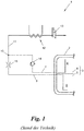
- Fig. 1 shows a tank system according to the prior art in a simplified hydraulic scheme.
- the tank system 1 has a temperature-insulated double-walled cryogenic container 2 in which a two-phase mixture 3 of cryogas 4 and cryogenic liquid 5 is received.
- the less dense cryogenic gas 4 is located substantially in a head region 6 of the container 2, from which head region 6 a first extraction line 7 for cryogas 4 starts, whereas the denser cryogenic liquid 5 collects in a bottom region 8 of the container 2, from which bottom region 8 a second extraction line 9 for Kryockenkeit 5 goes out.
- Both discharge lines 7, 9 open at a junction 10 in a feed line 11.
- the feed line 11 is subsequently passed through a heating element 12, for example a heat exchanger, in which the cryogenic two-phase mixture 3 is evaporated.
- a subsequent to the heating element 12 and thus lying outside the cryogenic range switching valve 13 opens or closes the feed line in the direction of the consumer, such as a vehicle drive.
- the switching valve 13 serves as an automatic shut-off valve and must, like all upstream elements, be specially protected against damage from the outside.
- cryocontainer 2 is under a pressure between about 7 to 10 bar, at which a refueling takes place, and about 16 bar, above which a controlled boil-off over in Fig. 1 not shown safety valves.
- the container pressure in the cryocontainer 2 increases during standstill periods, that is to say without consumption, by about 1 bar per day, for example.
- cryogenic liquid 5 In order to reduce the container pressure rapidly after a longer standstill and thus to minimize evaporation losses as much as possible, it is preferable to remove cryogas 4, since this reduces the container pressure much more rapidly than the removal of cryogenic liquid 5. In the case of low tank pressure and / or high power requirement of the consumer, however, primarily cryogenic liquid 5 should be used be removed.
- a so-called "economizer circuit" is known from the prior art, which provides a pressure relief valve 14 in the first sampling line 7 and a throttle 15 in the second sampling line 9.
- the pressure relief valve 14 opens the first extraction line 7 when the tank pressure exceeds a threshold and therefore primarily cryogenic gas 4 is to be supplied to the consumer, and closes the first extraction line 7 falls below the threshold.
- the throttle 15 reduces the pressure in the second extraction line 9 by, for example, 1 bar in order to give priority to open cryogenic valve 14 at the junction 10 Kryogas 4 and so reduce the pressure vessel.
- a disadvantage of the economizer circuit is that the throttle 15 permanently reduces the pressure in the second extraction line 9, so that the tank pressure ultimately remains higher, for example, by 1 bar than in the feed line. Furthermore, as a result of at least slight admixture of cryogenic liquid 5 in the feed line 11, the reduction of the container pressure is slowed even when priority is taken of cryogas 4.
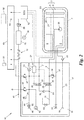
- FIG. 2 shows an embodiment of an inventive tank system 16, eg for the fuel of a vehicle, which can be operated without economizer circuit.
- the tank system 16 comprises a cryocontainer 2, which contains a two-phase mixture 3 of cryogas 4 and cryogenic liquid 5.
- a valve assembly 17 of the tank system 16 Connected to the cryocontainer 2 or at least partially integrated therein is a valve assembly 17 of the tank system 16, which is particularly protected against damage from the outside for use in vehicles - as well as the cryocontainer 2 itself.
- the control panel 18 includes, inter alia, a filler neck 19 with a guided into the cryocontainer 2 filling line 20 with spray nozzle 21 for filling the container 2. For easier filling, the filling line 20 against the Filler 19 locking check valve 22 have.
- a first removal line 7 starts from the head area 6 of the container 2 and removes this cryogas 4.
- the cryogenic liquid 5 collecting in the bottom area 8 of the container 2 is removed by a second removal line 9 emanating there.
- both discharge lines 7, 9 open at a connection 23 in a single, common feed line eleventh
- the feed line 11 leads - optionally backed by a pipe rupture valve 24 - out of the valve assembly 17 and through a heating element 12 through to a consumer M, eg a vehicle drive.
- the heating element 12 heats kryogas 4 or cryogenic liquid 5 in the feed line 11 to approximately normal temperature and thereby completely vaporizes any cryogenic liquid 5.
- the feed line 11 on the consumer side of the heating element 12, a buffer memory 25 and a pressure control valve 26 for uniform, regulated supply of the load M have.
- the tank system 16 also has a valve circuit 27.
- the valve circuit 27 may be, for example, a single 4-way valve or a single 3-way valve, in which latter case the connection 23 is integrated in the 3-way valve.
- the valve circuit 27 comprises two separate controllable switching valves 28, 29, u.zw. a first switching valve 28 which opens the first withdrawal line 7 or at least closes in the direction of the consumer M and a second switching valve 29 which opens the second withdrawal line 9 or closes it at least in the direction of the consumer M.
- the second removal line 9 does not open into the feed line 11, but into a separate feed line, which is guided by a further heating element separate from said heating element 12 and supplies the consumer M, e.g. a vehicle engine, feeds.
- the first extraction line 7 feeds via the feed line 11 and the heating element 12 either a separate consumer, e.g. a parking heater of a vehicle, or the same consumer M as the other feed line.
- the valve circuit 27 assumes the first switching state S 1 when the measured container pressure P 1 is greater than a predetermined first threshold value ⁇ 1 , and the second switching state S 2 when the measured container pressure P 1 is smaller than the first threshold value ⁇ 1 . Due to the exclusive removal of cryogas 4 in the first switching state S 1 , the container pressure P 1 is reduced as quickly as possible, since cryotube 4 has an approximately 600 times lower volumetric energy density compared to cryogenic liquid 5.
- the tank system 16 further comprises a first pressure sensor 30 for measuring the tank pressure P 1 .
- the first pressure sensor 30 is disposed inside the container 2 or outside, according to FIG Fig. 2
- the valve circuit 27 includes a controller 31a, eg a mechanical pressure switch or control electronics, which is connected to the first pressure sensor 30, the container pressure P 1 and its measured values and receives in dependence of which the valve circuit 27 and the first and second switching valve 28, 29 controls.
- Fig. 3b shows, the valve circuit 27 assumes the third switching state S 3 when the measured container pressure P 1 is greater than the first threshold ⁇ 1 and at the same time a consumer-side feed pressure P 2 in the feed line 11 is smaller than a predetermined second threshold ⁇ 2 .
- the tank system 16 may have a second pressure sensor 32 connected to the valve circuit 27 for this purpose.
- the Fig. 3a and 3b illustrate the three switching states S 1 , S 2 , S 3 during operation of the tank system 16, ie when dining the consumer M.
- a first threshold ⁇ 1 exceeding tank pressure P 1 is therefore the cryocontainer 2 exclusively Kryogas 4 removed (first switching state S 1 ).
- the valve circuit 27 additionally opens the second extraction line 9, so in addition kryoironkeit 5 enters the feed line 11 to evaporate in the heating element 12 and the consumer M to be supplied (third switching state S 3 ).
- the container pressure P 1 irrespective of whether it starts from the first switching state S 1 or the third switching state S 3 , falls below the first threshold value ⁇ 1 , then it closes Valve circuit 27, the first extraction line 7 and opens the second extraction line 9 or keeps them open (second switching state S 2 ), and in each case vice versa.
- the said separate consumer is fed by means of the first removal line 7, in which case the first removal line is closed at container pressure P 1 falling below the first threshold value ⁇ 1 (second switching state S 2 ).
- the valve circuit 27 is further between the aforementioned switching states S 1 and S 2 or S 1 , S 2 and S 3 (if provided) and one in the Fig. 3a and 3b not shown state switchable, in which both sampling lines 7, 9 are closed at least in the direction of the consumer M.
- This fourth switching state corresponds to a shutdown of the container 2 together with the valve assembly 17, for example, because the consumer M has no need or for safety reasons in case of damage from the outside, such as an accident of the vehicle.
- the first threshold value ⁇ 1 is, for example, less than 12 bar, preferably less than 10 bar, more preferably between about 7 and about 9 bar, the vessel pressure P 1 as quickly as possible to this level. If the cryocontainer 2 is designed to accommodate another cryogenic two-phase mixture 3, then the first threshold value ⁇ 1 is determined as required.
- the valve circuit 27 for the first and / or the second extraction line 7, 9 also has a check valve 33, 34, which leaves the respective extraction line 7, 9 open when closing in the direction of the consumer M in the direction of the container 2.
- the first switching valve 28 and the second switching valve 29 each have such a check valve 33 or 34 integrated;
- at least one of the check valves 33, 34 could also be arranged in a separate bypass line of the first or second switching valve 28, 29 or the valve circuit 27.
- the second extraction line 9 for example in the bottom region 8 of the container 2 or at another point a pump 35 to cryogenic liquid 5 from the cryocontainer 2, even at low tank pressure P 1 of eg less than about 7 bar safely in the second Extraction line 9 to promote. So that there is no overpressure situation in the second extraction line 9, if this is closed by the valve circuit 27, the second extraction line 9 in the example of Fig. 2
- the overpressure valve 36 is seated in the valve assembly 17, but it could alternatively also be arranged, for example, in the interior of the container 2, and could in each case open into the open; However, the pressure relief valve 36 preferably discharges into a line leading back into the cryocontainer 2, in this case an optional separate drain line 37 of the container 2.
- the drain line 37 connects the bottom portion 8 of the container 2 with the control panel 18, where for manual emptying of the container 2, a manual shut-off valve 38 is provided.
- the first removal line 7 an optional check valve 39, which prevents penetration of the cryogenic liquid 5 into the first withdrawal line 7 and thus short circuit funding from the pump 35 via the second withdrawal line 9, the connection point 23 and the first withdrawal line 7 back into the cryocontainer 2.
- the check valve 39 is seated between connection point 23 and the valve circuit 27 or the first switching valve 28;
- the non-return valve 39 could alternatively also be arranged on the container side of the valve circuit 27 or of the first switching valve 28.
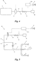
- Fig. 4 shows the general case of the tank system with the cryocontainer 2, which receives the two-phase mixture 3 of cryogas 4 and cryogenic liquid 5, the feed line 11, which the consumer M of at least one extraction line, ie emanating from the cryocontainer 2 first extraction line 7 and / or from Cryo container 2 outgoing second extraction line 9, from feeds, and the heating element 12, through which the feed line 11 is guided.
- the valve circuit 27 is arranged in the feed line 11 or in the at least one extraction line 7, 9, but in any case the container side of the heating element 12.
- the valve circuit 27 is electrically controlled by an electrical control 31b such that it controls the at least one extraction line 7, 9 - ie in the case that both extraction lines 7, 9, in the feed line 11 open, these two extraction lines 7, 9 - or the supply line 11 on or off, thus enabling the food of the consumer M or prevents.
- the controller 31b itself is connected to a sensor, eg a key switch S of an ignition lock or a crash sensor of a vehicle, which influences the controller 31b.
- Fig. 5 shows an embodiment of the tank system 16 with first and second extraction lines 7, 9, which as in the example of Fig. 1 form with pressure relief valve 14 and throttle 15 an economizer circuit, where, however, contrary Fig. 1 the valve circuit 27 - formed here as a single electromagnetic switching valve - container side of the heating element 12 is arranged in the feed line 11.
- valve circuit 27 or switching valves 28, 29 are arranged in the first and / or second withdrawal line, and further switching states S 1 , S 2 and / or S 3 as a function of container pressure P 1 and / or feed pressure P 2 , were mentioned above in connection with the Fig. 2 . 3a and 3b explained in detail.
- Fig. 6a and 6b For example, two or more tank systems 1, 16 can be grouped together and feed a consumer M together. Since according to the prior art ( Fig. 4a ) the heating element 12 must be arranged according to the guideline ECE R110 for vehicles within the protected area of the shut-off valves 13, in the prior art is an interconnection of two tank systems 1 only in the normal temperature range, ie Consumer side of the heating elements 12 possible, which requires multiple heating elements 12.
- valve circuit 27 of the tank system 16 according to the invention allows a protective shutdown already in the cryogenic region, so that two or more tank systems 16 according to the invention are combined to form a plant 40 at a merger point 41, which is the container side of the heating element 12.
- the so-combined feed lines 11 can thus be performed over a single common heating element 12.
- the tank system 16 may have other components, such as Fig. 2 exemplifies.
- the container pressure P 1 if desired, can be output on a display 42, for example on the control console 18.
- the feed line 11 can have an eg manual shut-off valve 43 on the operating console 18.
- an optional vent line 44 with connection piece 46 and shut-off valve 45 could be guided into the control console 18.
- an exhaust steam valve 47 which opens at 16 bar when using LNG, for example at a tank pressure P 1
- an emergency exhaust valve 48 which opens at 22 bar, for example, in a tank pressure P 1 , for example in the first extraction line. 7 be provided.
- the heating element 12 may each be a heat exchanger, which is fed via a connecting rail 49 of the tank system 16 with waste heat from the vehicle engine.
- the connecting rail 49 may further support a connecting piece 50 for connecting the load M, eg vehicle engine, to the feed line 11.
- the exhaust steam and / or Notabdampfventile 47, 48 can be connected via the connecting rail 49 to an exhaust line (Vent Stack) 51 of the vehicle.
- An engine control unit (ECU) 52 of the vehicle may be connected via the connection rail 49 to the tank system 16, the valve assembly 17 and the valve circuit 27, for example with a level sensor 53 in the cryocontainer 2, the valve circuit 27, the first and second Switching valve 28, 29 and / or the first and second pressure sensor 30, 32nd
- the engine controller 52 may also assume control of the first and second switching valves 28, 29 and the valve circuit 27, respectively.
- the electric controller 31b and / or the controller 31a of the valve circuit 27 may be part of the engine controller 52.
Landscapes
- Engineering & Computer Science (AREA)
- Mechanical Engineering (AREA)
- General Engineering & Computer Science (AREA)
- Filling Or Discharging Of Gas Storage Vessels (AREA)
Priority Applications (7)
| Application Number | Priority Date | Filing Date | Title |
|---|---|---|---|
| PL16166738T PL3236133T3 (pl) | 2016-04-22 | 2016-04-22 | Układ zbiornika |
| RS20191699A RS59753B1 (sr) | 2016-04-22 | 2016-04-22 | Sistem rezervoara |
| PT161667381T PT3236133T (pt) | 2016-04-22 | 2016-04-22 | Sistema de tanque |
| ES16166738T ES2770673T3 (es) | 2016-04-22 | 2016-04-22 | Sistema de tanque |
| HUE16166738A HUE047498T2 (hu) | 2016-04-22 | 2016-04-22 | Tartályrendszer |
| SI201630608T SI3236133T1 (sl) | 2016-04-22 | 2016-04-22 | Sistem rezervoarja |
| EP16166738.1A EP3236133B1 (de) | 2016-04-22 | 2016-04-22 | Tanksystem |
Applications Claiming Priority (1)
| Application Number | Priority Date | Filing Date | Title |
|---|---|---|---|
| EP16166738.1A EP3236133B1 (de) | 2016-04-22 | 2016-04-22 | Tanksystem |
Publications (2)
| Publication Number | Publication Date |
|---|---|
| EP3236133A1 EP3236133A1 (de) | 2017-10-25 |
| EP3236133B1 true EP3236133B1 (de) | 2019-11-13 |
Family
ID=55809000
Family Applications (1)
| Application Number | Title | Priority Date | Filing Date |
|---|---|---|---|
| EP16166738.1A Active EP3236133B1 (de) | 2016-04-22 | 2016-04-22 | Tanksystem |
Country Status (7)
| Country | Link |
|---|---|
| EP (1) | EP3236133B1 (pl) |
| ES (1) | ES2770673T3 (pl) |
| HU (1) | HUE047498T2 (pl) |
| PL (1) | PL3236133T3 (pl) |
| PT (1) | PT3236133T (pl) |
| RS (1) | RS59753B1 (pl) |
| SI (1) | SI3236133T1 (pl) |
Families Citing this family (5)
| Publication number | Priority date | Publication date | Assignee | Title |
|---|---|---|---|---|
| ES2967317T3 (es) * | 2017-11-23 | 2024-04-29 | Salzburger Aluminium Ag | Sistema de depósito para un vehículo de piso bajo |
| RS60644B1 (sr) * | 2017-11-23 | 2020-09-30 | Salzburger Aluminium Ag | Sistem rezervoara za vozila niskog poda |
| FR3094070B1 (fr) * | 2019-03-21 | 2021-10-15 | Air Liquide | Dispositif et procédé de stockage et de fourniture de carburant fluide. |
| WO2021102489A1 (de) * | 2019-11-29 | 2021-06-03 | Cryoshelter Gmbh | System mit zumindest zwei kryobehältern zur bereitstellung eines fluids |
| WO2022067362A1 (de) * | 2020-09-29 | 2022-04-07 | Cryoshelter Gmbh | Sicherheitsentnahmesystem für einen kryobehälter |
Citations (1)
| Publication number | Priority date | Publication date | Assignee | Title |
|---|---|---|---|---|
| WO2016172803A1 (en) * | 2015-04-30 | 2016-11-03 | Westport Power Inc. | Intelligent pressure management system for cryogenic fluid systems |
Family Cites Families (3)
| Publication number | Priority date | Publication date | Assignee | Title |
|---|---|---|---|---|
| CN201186605Y (zh) * | 2008-04-07 | 2009-01-28 | 山东绿能燃气实业有限责任公司 | 液化天然气汽车双罐或多罐供气系统 |
| DE102011117158B4 (de) * | 2011-10-28 | 2016-08-11 | Magna Steyr Fahrzeugtechnik Ag & Co. Kg | Tanksystem für ein Kraftfahrzeug sowie Betriebsverfahren hierfür |
| CA2833619C (en) * | 2013-11-21 | 2020-06-30 | Westport Power Inc. | Method and system for delivering a gaseous fuel into the air intake system of an internal combustion engine |
-
2016
- 2016-04-22 ES ES16166738T patent/ES2770673T3/es active Active
- 2016-04-22 HU HUE16166738A patent/HUE047498T2/hu unknown
- 2016-04-22 PT PT161667381T patent/PT3236133T/pt unknown
- 2016-04-22 PL PL16166738T patent/PL3236133T3/pl unknown
- 2016-04-22 RS RS20191699A patent/RS59753B1/sr unknown
- 2016-04-22 EP EP16166738.1A patent/EP3236133B1/de active Active
- 2016-04-22 SI SI201630608T patent/SI3236133T1/sl unknown
Patent Citations (1)
| Publication number | Priority date | Publication date | Assignee | Title |
|---|---|---|---|---|
| WO2016172803A1 (en) * | 2015-04-30 | 2016-11-03 | Westport Power Inc. | Intelligent pressure management system for cryogenic fluid systems |
Also Published As
| Publication number | Publication date |
|---|---|
| EP3236133A1 (de) | 2017-10-25 |
| SI3236133T1 (sl) | 2020-03-31 |
| ES2770673T3 (es) | 2020-07-02 |
| PL3236133T3 (pl) | 2020-05-18 |
| RS59753B1 (sr) | 2020-02-28 |
| PT3236133T (pt) | 2020-03-03 |
| HUE047498T2 (hu) | 2020-04-28 |
Similar Documents
| Publication | Publication Date | Title |
|---|---|---|
| EP3236133B1 (de) | Tanksystem | |
| EP3236132B1 (de) | Tanksystem | |
| EP3479007B1 (de) | Tankventil | |
| EP2831492B1 (de) | Betriebsverfahren für eine brennstoffzellen-anlage | |
| EP2831491B1 (de) | Betriebsverfahren für einen kryo-drucktank | |
| EP3961083B1 (de) | Tanksystem | |
| EP2909524B1 (de) | Verfahren zum befüllen einer kraftstoffspeicheranlage eines kraftfahrzeugs | |
| EP3715261B1 (de) | Treibstoffentnahmesystem, treibstofftankvorrichtung mit treibstoffentnahmesystem und brennstoffzellensystem mit treibstoffentnahmesystem | |
| EP3497361B1 (de) | Verfahren zum einstellen der temperatur und/oder des drucks von brennstoff, insbesondere von wasserstoff, in mehreren druckbehältern eines fahrzeugs auf jeweils einen temperatursollwert und/oder jeweils einen drucksollwert vor einem befüllungsvorgang der druckbehälter | |
| WO2017088944A1 (de) | Tankventil | |
| EP1192351A2 (de) | Kraftstoffzuführvorrichtung für einen verbrennungsmotor | |
| DE102009039079A1 (de) | Tankanordnung | |
| EP4248125B1 (de) | Verfahren zum betreiben einer mit gasförmigem brennstoff betriebenen antriebseinheit | |
| WO2018033295A1 (de) | Verfahren zum betrieb eines ventils eines druckbehältersystems sowie druckbehältersystem | |
| DE102015218986A1 (de) | Verfahren zum Abführen von Brennstoff aus einem Druckbehältersystem durch eine externe Brennstoffleitung sowie Druckbehältersystem | |
| DE102008063563A1 (de) | Kraftstoffversorgungssystem mit einem Tieftemperaturtank | |
| DE102012024717A1 (de) | Fahrzeug mit einem Flüssiggastank | |
| EP2792525A1 (de) | Vorrichtung zur Gasversorgung | |
| DE102019110350A1 (de) | Druckbehältersystem sowie Verfahren zum Betrieb eines Druckbehältersystems | |
| WO2019101382A1 (de) | Tanksystem für ein niederflur-fahrzeug | |
| DE102012218856A1 (de) | Kraftstoffspeicheranlage eines Kraftfahrzeugs | |
| EP4222405B1 (de) | Sicherheitsentnahmesystem für einen kryobehälter | |
| DE102014210242B4 (de) | Drucktankanordnung | |
| DE102017217348A1 (de) | Druckbehältersystem und Verfahren zum Zuführen von Brennstoff aus einem Druckbehältersystem | |
| DE102022109097A1 (de) | Verfahren und Vorrichtung zur Versorgung von Verbrauchern mit Wasserstoff |
Legal Events
| Date | Code | Title | Description |
|---|---|---|---|
| PUAI | Public reference made under article 153(3) epc to a published international application that has entered the european phase |
Free format text: ORIGINAL CODE: 0009012 |
|
| STAA | Information on the status of an ep patent application or granted ep patent |
Free format text: STATUS: THE APPLICATION HAS BEEN PUBLISHED |
|
| AK | Designated contracting states |
Kind code of ref document: A1 Designated state(s): AL AT BE BG CH CY CZ DE DK EE ES FI FR GB GR HR HU IE IS IT LI LT LU LV MC MK MT NL NO PL PT RO RS SE SI SK SM TR |
|
| AX | Request for extension of the european patent |
Extension state: BA ME |
|
| STAA | Information on the status of an ep patent application or granted ep patent |
Free format text: STATUS: REQUEST FOR EXAMINATION WAS MADE |
|
| 17P | Request for examination filed |
Effective date: 20180316 |
|
| RBV | Designated contracting states (corrected) |
Designated state(s): AL AT BE BG CH CY CZ DE DK EE ES FI FR GB GR HR HU IE IS IT LI LT LU LV MC MK MT NL NO PL PT RO RS SE SI SK SM TR |
|
| STAA | Information on the status of an ep patent application or granted ep patent |
Free format text: STATUS: EXAMINATION IS IN PROGRESS |
|
| 17Q | First examination report despatched |
Effective date: 20190306 |
|
| GRAP | Despatch of communication of intention to grant a patent |
Free format text: ORIGINAL CODE: EPIDOSNIGR1 |
|
| STAA | Information on the status of an ep patent application or granted ep patent |
Free format text: STATUS: GRANT OF PATENT IS INTENDED |
|
| INTG | Intention to grant announced |
Effective date: 20190619 |
|
| GRAS | Grant fee paid |
Free format text: ORIGINAL CODE: EPIDOSNIGR3 |
|
| GRAA | (expected) grant |
Free format text: ORIGINAL CODE: 0009210 |
|
| STAA | Information on the status of an ep patent application or granted ep patent |
Free format text: STATUS: THE PATENT HAS BEEN GRANTED |
|
| AK | Designated contracting states |
Kind code of ref document: B1 Designated state(s): AL AT BE BG CH CY CZ DE DK EE ES FI FR GB GR HR HU IE IS IT LI LT LU LV MC MK MT NL NO PL PT RO RS SE SI SK SM TR |
|
| REG | Reference to a national code |
Ref country code: AT Ref legal event code: REF Ref document number: 1202022 Country of ref document: AT Kind code of ref document: T Effective date: 20191115 Ref country code: CH Ref legal event code: EP |
|
| REG | Reference to a national code |
Ref country code: DE Ref legal event code: R096 Ref document number: 502016007526 Country of ref document: DE |
|
| REG | Reference to a national code |
Ref country code: IE Ref legal event code: FG4D Free format text: LANGUAGE OF EP DOCUMENT: GERMAN |
|
| REG | Reference to a national code |
Ref country code: RO Ref legal event code: EPE |
|
| REG | Reference to a national code |
Ref country code: SK Ref legal event code: T3 Ref document number: E 33037 Country of ref document: SK Ref country code: PT Ref legal event code: SC4A Ref document number: 3236133 Country of ref document: PT Date of ref document: 20200303 Kind code of ref document: T Free format text: AVAILABILITY OF NATIONAL TRANSLATION Effective date: 20200213 |
|
| REG | Reference to a national code |
Ref country code: SE Ref legal event code: TRGR |
|
| REG | Reference to a national code |
Ref country code: LT Ref legal event code: MG4D |
|
| REG | Reference to a national code |
Ref country code: HU Ref legal event code: AG4A Ref document number: E047498 Country of ref document: HU |
|
| PG25 | Lapsed in a contracting state [announced via postgrant information from national office to epo] |
Ref country code: NO Free format text: LAPSE BECAUSE OF FAILURE TO SUBMIT A TRANSLATION OF THE DESCRIPTION OR TO PAY THE FEE WITHIN THE PRESCRIBED TIME-LIMIT Effective date: 20200213 Ref country code: LV Free format text: LAPSE BECAUSE OF FAILURE TO SUBMIT A TRANSLATION OF THE DESCRIPTION OR TO PAY THE FEE WITHIN THE PRESCRIBED TIME-LIMIT Effective date: 20191113 Ref country code: FI Free format text: LAPSE BECAUSE OF FAILURE TO SUBMIT A TRANSLATION OF THE DESCRIPTION OR TO PAY THE FEE WITHIN THE PRESCRIBED TIME-LIMIT Effective date: 20191113 Ref country code: GR Free format text: LAPSE BECAUSE OF FAILURE TO SUBMIT A TRANSLATION OF THE DESCRIPTION OR TO PAY THE FEE WITHIN THE PRESCRIBED TIME-LIMIT Effective date: 20200214 Ref country code: LT Free format text: LAPSE BECAUSE OF FAILURE TO SUBMIT A TRANSLATION OF THE DESCRIPTION OR TO PAY THE FEE WITHIN THE PRESCRIBED TIME-LIMIT Effective date: 20191113 |
|
| REG | Reference to a national code |
Ref country code: NL Ref legal event code: FP |
|
| PG25 | Lapsed in a contracting state [announced via postgrant information from national office to epo] |
Ref country code: IS Free format text: LAPSE BECAUSE OF FAILURE TO SUBMIT A TRANSLATION OF THE DESCRIPTION OR TO PAY THE FEE WITHIN THE PRESCRIBED TIME-LIMIT Effective date: 20200313 Ref country code: HR Free format text: LAPSE BECAUSE OF FAILURE TO SUBMIT A TRANSLATION OF THE DESCRIPTION OR TO PAY THE FEE WITHIN THE PRESCRIBED TIME-LIMIT Effective date: 20191113 |
|
| PG25 | Lapsed in a contracting state [announced via postgrant information from national office to epo] |
Ref country code: AL Free format text: LAPSE BECAUSE OF FAILURE TO SUBMIT A TRANSLATION OF THE DESCRIPTION OR TO PAY THE FEE WITHIN THE PRESCRIBED TIME-LIMIT Effective date: 20191113 |
|
| REG | Reference to a national code |
Ref country code: ES Ref legal event code: FG2A Ref document number: 2770673 Country of ref document: ES Kind code of ref document: T3 Effective date: 20200702 |
|
| PG25 | Lapsed in a contracting state [announced via postgrant information from national office to epo] |
Ref country code: DK Free format text: LAPSE BECAUSE OF FAILURE TO SUBMIT A TRANSLATION OF THE DESCRIPTION OR TO PAY THE FEE WITHIN THE PRESCRIBED TIME-LIMIT Effective date: 20191113 Ref country code: EE Free format text: LAPSE BECAUSE OF FAILURE TO SUBMIT A TRANSLATION OF THE DESCRIPTION OR TO PAY THE FEE WITHIN THE PRESCRIBED TIME-LIMIT Effective date: 20191113 |
|
| REG | Reference to a national code |
Ref country code: DE Ref legal event code: R097 Ref document number: 502016007526 Country of ref document: DE |
|
| PG25 | Lapsed in a contracting state [announced via postgrant information from national office to epo] |
Ref country code: SM Free format text: LAPSE BECAUSE OF FAILURE TO SUBMIT A TRANSLATION OF THE DESCRIPTION OR TO PAY THE FEE WITHIN THE PRESCRIBED TIME-LIMIT Effective date: 20191113 |
|
| PLBE | No opposition filed within time limit |
Free format text: ORIGINAL CODE: 0009261 |
|
| STAA | Information on the status of an ep patent application or granted ep patent |
Free format text: STATUS: NO OPPOSITION FILED WITHIN TIME LIMIT |
|
| 26N | No opposition filed |
Effective date: 20200814 |
|
| PG25 | Lapsed in a contracting state [announced via postgrant information from national office to epo] |
Ref country code: MC Free format text: LAPSE BECAUSE OF FAILURE TO SUBMIT A TRANSLATION OF THE DESCRIPTION OR TO PAY THE FEE WITHIN THE PRESCRIBED TIME-LIMIT Effective date: 20191113 |
|
| REG | Reference to a national code |
Ref country code: CH Ref legal event code: PL |
|
| PG25 | Lapsed in a contracting state [announced via postgrant information from national office to epo] |
Ref country code: CH Free format text: LAPSE BECAUSE OF NON-PAYMENT OF DUE FEES Effective date: 20200430 Ref country code: LU Free format text: LAPSE BECAUSE OF NON-PAYMENT OF DUE FEES Effective date: 20200422 Ref country code: LI Free format text: LAPSE BECAUSE OF NON-PAYMENT OF DUE FEES Effective date: 20200430 |
|
| REG | Reference to a national code |
Ref country code: BE Ref legal event code: MM Effective date: 20200430 |
|
| PG25 | Lapsed in a contracting state [announced via postgrant information from national office to epo] |
Ref country code: BE Free format text: LAPSE BECAUSE OF NON-PAYMENT OF DUE FEES Effective date: 20200430 |
|
| PG25 | Lapsed in a contracting state [announced via postgrant information from national office to epo] |
Ref country code: IE Free format text: LAPSE BECAUSE OF NON-PAYMENT OF DUE FEES Effective date: 20200422 |
|
| PG25 | Lapsed in a contracting state [announced via postgrant information from national office to epo] |
Ref country code: MT Free format text: LAPSE BECAUSE OF FAILURE TO SUBMIT A TRANSLATION OF THE DESCRIPTION OR TO PAY THE FEE WITHIN THE PRESCRIBED TIME-LIMIT Effective date: 20191113 Ref country code: CY Free format text: LAPSE BECAUSE OF FAILURE TO SUBMIT A TRANSLATION OF THE DESCRIPTION OR TO PAY THE FEE WITHIN THE PRESCRIBED TIME-LIMIT Effective date: 20191113 |
|
| PG25 | Lapsed in a contracting state [announced via postgrant information from national office to epo] |
Ref country code: MK Free format text: LAPSE BECAUSE OF FAILURE TO SUBMIT A TRANSLATION OF THE DESCRIPTION OR TO PAY THE FEE WITHIN THE PRESCRIBED TIME-LIMIT Effective date: 20191113 |
|
| P01 | Opt-out of the competence of the unified patent court (upc) registered |
Effective date: 20230517 |
|
| PGFP | Annual fee paid to national office [announced via postgrant information from national office to epo] |
Ref country code: RS Payment date: 20230420 Year of fee payment: 8 Ref country code: RO Payment date: 20230419 Year of fee payment: 8 Ref country code: CZ Payment date: 20230411 Year of fee payment: 8 |
|
| PGFP | Annual fee paid to national office [announced via postgrant information from national office to epo] |
Ref country code: TR Payment date: 20230418 Year of fee payment: 8 Ref country code: SK Payment date: 20230418 Year of fee payment: 8 Ref country code: HU Payment date: 20230419 Year of fee payment: 8 |
|
| REG | Reference to a national code |
Ref country code: DE Ref legal event code: R081 Ref document number: 502016007526 Country of ref document: DE Owner name: SAG GROUP B.V., NL Free format text: FORMER OWNER: SALZBURGER ALUMINIUM AKTIENGESELLSCHAFT, LEND, AT |
|
| REG | Reference to a national code |
Ref country code: NL Ref legal event code: PD Owner name: SAG GROUP B.V; NL Free format text: DETAILS ASSIGNMENT: CHANGE OF OWNER(S), ASSIGNMENT; FORMER OWNER NAME: SALZBURGER ALUMINIUM GMBH Effective date: 20241022 Ref country code: DE Ref legal event code: R081 Ref document number: 502016007526 Country of ref document: DE Owner name: SAG GROUP B.V., NL Free format text: FORMER OWNER: SALZBURGER ALUMINIUM GMBH, LEND, AT |
|
| REG | Reference to a national code |
Ref country code: GB Ref legal event code: 732E Free format text: REGISTERED BETWEEN 20241017 AND 20241023 |
|
| REG | Reference to a national code |
Ref country code: SK Ref legal event code: MM4A Ref document number: E 33037 Country of ref document: SK Effective date: 20240422 |
|
| REG | Reference to a national code |
Ref country code: ES Ref legal event code: PC2A Owner name: SAG GROUP B.V. Effective date: 20241204 |
|
| PG25 | Lapsed in a contracting state [announced via postgrant information from national office to epo] |
Ref country code: HU Free format text: LAPSE BECAUSE OF NON-PAYMENT OF DUE FEES Effective date: 20240423 |
|
| REG | Reference to a national code |
Ref country code: AT Ref legal event code: PC Ref document number: 1202022 Country of ref document: AT Kind code of ref document: T Owner name: SAG GROUP B. V., NL Effective date: 20241210 |
|
| PG25 | Lapsed in a contracting state [announced via postgrant information from national office to epo] |
Ref country code: CZ Free format text: LAPSE BECAUSE OF NON-PAYMENT OF DUE FEES Effective date: 20240422 |
|
| PG25 | Lapsed in a contracting state [announced via postgrant information from national office to epo] |
Ref country code: RO Free format text: LAPSE BECAUSE OF NON-PAYMENT OF DUE FEES Effective date: 20240422 Ref country code: SK Free format text: LAPSE BECAUSE OF NON-PAYMENT OF DUE FEES Effective date: 20240422 |
|
| PG25 | Lapsed in a contracting state [announced via postgrant information from national office to epo] |
Ref country code: RS Free format text: LAPSE BECAUSE OF NON-PAYMENT OF DUE FEES Effective date: 20240422 |
|
| PG25 | Lapsed in a contracting state [announced via postgrant information from national office to epo] |
Ref country code: SK Free format text: LAPSE BECAUSE OF NON-PAYMENT OF DUE FEES Effective date: 20240422 Ref country code: RS Free format text: LAPSE BECAUSE OF NON-PAYMENT OF DUE FEES Effective date: 20240422 Ref country code: RO Free format text: LAPSE BECAUSE OF NON-PAYMENT OF DUE FEES Effective date: 20240422 Ref country code: HU Free format text: LAPSE BECAUSE OF NON-PAYMENT OF DUE FEES Effective date: 20240423 Ref country code: CZ Free format text: LAPSE BECAUSE OF NON-PAYMENT OF DUE FEES Effective date: 20240422 |
|
| REG | Reference to a national code |
Ref country code: SI Ref legal event code: SP73 Owner name: SAG GROUP B.V.; NL Effective date: 20241016 |
|
| PGFP | Annual fee paid to national office [announced via postgrant information from national office to epo] |
Ref country code: SI Payment date: 20250409 Year of fee payment: 10 |
|
| PGFP | Annual fee paid to national office [announced via postgrant information from national office to epo] |
Ref country code: NL Payment date: 20250422 Year of fee payment: 10 |
|
| PGFP | Annual fee paid to national office [announced via postgrant information from national office to epo] |
Ref country code: PL Payment date: 20250416 Year of fee payment: 10 Ref country code: DE Payment date: 20250417 Year of fee payment: 10 |
|
| PGFP | Annual fee paid to national office [announced via postgrant information from national office to epo] |
Ref country code: GB Payment date: 20250423 Year of fee payment: 10 Ref country code: ES Payment date: 20250519 Year of fee payment: 10 |
|
| PGFP | Annual fee paid to national office [announced via postgrant information from national office to epo] |
Ref country code: IT Payment date: 20250430 Year of fee payment: 10 |
|
| PGFP | Annual fee paid to national office [announced via postgrant information from national office to epo] |
Ref country code: PT Payment date: 20250409 Year of fee payment: 10 |
|
| PGFP | Annual fee paid to national office [announced via postgrant information from national office to epo] |
Ref country code: FR Payment date: 20250422 Year of fee payment: 10 |
|
| PGFP | Annual fee paid to national office [announced via postgrant information from national office to epo] |
Ref country code: BG Payment date: 20250415 Year of fee payment: 10 |
|
| PGFP | Annual fee paid to national office [announced via postgrant information from national office to epo] |
Ref country code: AT Payment date: 20250327 Year of fee payment: 10 |
|
| PGFP | Annual fee paid to national office [announced via postgrant information from national office to epo] |
Ref country code: SE Payment date: 20250423 Year of fee payment: 10 |