EP3236133B1 - Tank system - Google Patents
Tank system Download PDFInfo
- Publication number
- EP3236133B1 EP3236133B1 EP16166738.1A EP16166738A EP3236133B1 EP 3236133 B1 EP3236133 B1 EP 3236133B1 EP 16166738 A EP16166738 A EP 16166738A EP 3236133 B1 EP3236133 B1 EP 3236133B1
- Authority
- EP
- European Patent Office
- Prior art keywords
- valve
- consumer
- extraction line
- line
- pressure
- Prior art date
- Legal status (The legal status is an assumption and is not a legal conclusion. Google has not performed a legal analysis and makes no representation as to the accuracy of the status listed.)
- Active
Links
Images


Classifications
-
- F—MECHANICAL ENGINEERING; LIGHTING; HEATING; WEAPONS; BLASTING
- F17—STORING OR DISTRIBUTING GASES OR LIQUIDS
- F17C—VESSELS FOR CONTAINING OR STORING COMPRESSED, LIQUEFIED OR SOLIDIFIED GASES; FIXED-CAPACITY GAS-HOLDERS; FILLING VESSELS WITH, OR DISCHARGING FROM VESSELS, COMPRESSED, LIQUEFIED, OR SOLIDIFIED GASES
- F17C9/00—Methods or apparatus for discharging liquefied or solidified gases from vessels not under pressure
- F17C9/02—Methods or apparatus for discharging liquefied or solidified gases from vessels not under pressure with change of state, e.g. vaporisation
-
- F—MECHANICAL ENGINEERING; LIGHTING; HEATING; WEAPONS; BLASTING
- F17—STORING OR DISTRIBUTING GASES OR LIQUIDS
- F17C—VESSELS FOR CONTAINING OR STORING COMPRESSED, LIQUEFIED OR SOLIDIFIED GASES; FIXED-CAPACITY GAS-HOLDERS; FILLING VESSELS WITH, OR DISCHARGING FROM VESSELS, COMPRESSED, LIQUEFIED, OR SOLIDIFIED GASES
- F17C2205/00—Vessel construction, in particular mounting arrangements, attachments or identifications means
- F17C2205/03—Fluid connections, filters, valves, closure means or other attachments
- F17C2205/0302—Fittings, valves, filters, or components in connection with the gas storage device
- F17C2205/0323—Valves
- F17C2205/0326—Valves electrically actuated
-
- F—MECHANICAL ENGINEERING; LIGHTING; HEATING; WEAPONS; BLASTING
- F17—STORING OR DISTRIBUTING GASES OR LIQUIDS
- F17C—VESSELS FOR CONTAINING OR STORING COMPRESSED, LIQUEFIED OR SOLIDIFIED GASES; FIXED-CAPACITY GAS-HOLDERS; FILLING VESSELS WITH, OR DISCHARGING FROM VESSELS, COMPRESSED, LIQUEFIED, OR SOLIDIFIED GASES
- F17C2221/00—Handled fluid, in particular type of fluid
- F17C2221/01—Pure fluids
- F17C2221/012—Hydrogen
-
- F—MECHANICAL ENGINEERING; LIGHTING; HEATING; WEAPONS; BLASTING
- F17—STORING OR DISTRIBUTING GASES OR LIQUIDS
- F17C—VESSELS FOR CONTAINING OR STORING COMPRESSED, LIQUEFIED OR SOLIDIFIED GASES; FIXED-CAPACITY GAS-HOLDERS; FILLING VESSELS WITH, OR DISCHARGING FROM VESSELS, COMPRESSED, LIQUEFIED, OR SOLIDIFIED GASES
- F17C2221/00—Handled fluid, in particular type of fluid
- F17C2221/03—Mixtures
- F17C2221/032—Hydrocarbons
- F17C2221/033—Methane, e.g. natural gas, CNG, LNG, GNL, GNC, PLNG
-
- F—MECHANICAL ENGINEERING; LIGHTING; HEATING; WEAPONS; BLASTING
- F17—STORING OR DISTRIBUTING GASES OR LIQUIDS
- F17C—VESSELS FOR CONTAINING OR STORING COMPRESSED, LIQUEFIED OR SOLIDIFIED GASES; FIXED-CAPACITY GAS-HOLDERS; FILLING VESSELS WITH, OR DISCHARGING FROM VESSELS, COMPRESSED, LIQUEFIED, OR SOLIDIFIED GASES
- F17C2223/00—Handled fluid before transfer, i.e. state of fluid when stored in the vessel or before transfer from the vessel
- F17C2223/01—Handled fluid before transfer, i.e. state of fluid when stored in the vessel or before transfer from the vessel characterised by the phase
- F17C2223/0146—Two-phase
- F17C2223/0153—Liquefied gas, e.g. LPG, GPL
- F17C2223/0161—Liquefied gas, e.g. LPG, GPL cryogenic, e.g. LNG, GNL, PLNG
-
- F—MECHANICAL ENGINEERING; LIGHTING; HEATING; WEAPONS; BLASTING
- F17—STORING OR DISTRIBUTING GASES OR LIQUIDS
- F17C—VESSELS FOR CONTAINING OR STORING COMPRESSED, LIQUEFIED OR SOLIDIFIED GASES; FIXED-CAPACITY GAS-HOLDERS; FILLING VESSELS WITH, OR DISCHARGING FROM VESSELS, COMPRESSED, LIQUEFIED, OR SOLIDIFIED GASES
- F17C2223/00—Handled fluid before transfer, i.e. state of fluid when stored in the vessel or before transfer from the vessel
- F17C2223/03—Handled fluid before transfer, i.e. state of fluid when stored in the vessel or before transfer from the vessel characterised by the pressure level
- F17C2223/033—Small pressure, e.g. for liquefied gas
-
- F—MECHANICAL ENGINEERING; LIGHTING; HEATING; WEAPONS; BLASTING
- F17—STORING OR DISTRIBUTING GASES OR LIQUIDS
- F17C—VESSELS FOR CONTAINING OR STORING COMPRESSED, LIQUEFIED OR SOLIDIFIED GASES; FIXED-CAPACITY GAS-HOLDERS; FILLING VESSELS WITH, OR DISCHARGING FROM VESSELS, COMPRESSED, LIQUEFIED, OR SOLIDIFIED GASES
- F17C2223/00—Handled fluid before transfer, i.e. state of fluid when stored in the vessel or before transfer from the vessel
- F17C2223/04—Handled fluid before transfer, i.e. state of fluid when stored in the vessel or before transfer from the vessel characterised by other properties of handled fluid before transfer
- F17C2223/042—Localisation of the removal point
- F17C2223/043—Localisation of the removal point in the gas
- F17C2223/045—Localisation of the removal point in the gas with a dip tube
-
- F—MECHANICAL ENGINEERING; LIGHTING; HEATING; WEAPONS; BLASTING
- F17—STORING OR DISTRIBUTING GASES OR LIQUIDS
- F17C—VESSELS FOR CONTAINING OR STORING COMPRESSED, LIQUEFIED OR SOLIDIFIED GASES; FIXED-CAPACITY GAS-HOLDERS; FILLING VESSELS WITH, OR DISCHARGING FROM VESSELS, COMPRESSED, LIQUEFIED, OR SOLIDIFIED GASES
- F17C2223/00—Handled fluid before transfer, i.e. state of fluid when stored in the vessel or before transfer from the vessel
- F17C2223/04—Handled fluid before transfer, i.e. state of fluid when stored in the vessel or before transfer from the vessel characterised by other properties of handled fluid before transfer
- F17C2223/042—Localisation of the removal point
- F17C2223/046—Localisation of the removal point in the liquid
- F17C2223/047—Localisation of the removal point in the liquid with a dip tube
-
- F—MECHANICAL ENGINEERING; LIGHTING; HEATING; WEAPONS; BLASTING
- F17—STORING OR DISTRIBUTING GASES OR LIQUIDS
- F17C—VESSELS FOR CONTAINING OR STORING COMPRESSED, LIQUEFIED OR SOLIDIFIED GASES; FIXED-CAPACITY GAS-HOLDERS; FILLING VESSELS WITH, OR DISCHARGING FROM VESSELS, COMPRESSED, LIQUEFIED, OR SOLIDIFIED GASES
- F17C2225/00—Handled fluid after transfer, i.e. state of fluid after transfer from the vessel
- F17C2225/04—Handled fluid after transfer, i.e. state of fluid after transfer from the vessel characterised by other properties of handled fluid after transfer
- F17C2225/042—Localisation of the filling point
- F17C2225/043—Localisation of the filling point in the gas
- F17C2225/045—Localisation of the filling point in the gas with a dip tube
-
- F—MECHANICAL ENGINEERING; LIGHTING; HEATING; WEAPONS; BLASTING
- F17—STORING OR DISTRIBUTING GASES OR LIQUIDS
- F17C—VESSELS FOR CONTAINING OR STORING COMPRESSED, LIQUEFIED OR SOLIDIFIED GASES; FIXED-CAPACITY GAS-HOLDERS; FILLING VESSELS WITH, OR DISCHARGING FROM VESSELS, COMPRESSED, LIQUEFIED, OR SOLIDIFIED GASES
- F17C2227/00—Transfer of fluids, i.e. method or means for transferring the fluid; Heat exchange with the fluid
- F17C2227/01—Propulsion of the fluid
- F17C2227/0128—Propulsion of the fluid with pumps or compressors
- F17C2227/0135—Pumps
-
- F—MECHANICAL ENGINEERING; LIGHTING; HEATING; WEAPONS; BLASTING
- F17—STORING OR DISTRIBUTING GASES OR LIQUIDS
- F17C—VESSELS FOR CONTAINING OR STORING COMPRESSED, LIQUEFIED OR SOLIDIFIED GASES; FIXED-CAPACITY GAS-HOLDERS; FILLING VESSELS WITH, OR DISCHARGING FROM VESSELS, COMPRESSED, LIQUEFIED, OR SOLIDIFIED GASES
- F17C2227/00—Transfer of fluids, i.e. method or means for transferring the fluid; Heat exchange with the fluid
- F17C2227/03—Heat exchange with the fluid
- F17C2227/0302—Heat exchange with the fluid by heating
-
- F—MECHANICAL ENGINEERING; LIGHTING; HEATING; WEAPONS; BLASTING
- F17—STORING OR DISTRIBUTING GASES OR LIQUIDS
- F17C—VESSELS FOR CONTAINING OR STORING COMPRESSED, LIQUEFIED OR SOLIDIFIED GASES; FIXED-CAPACITY GAS-HOLDERS; FILLING VESSELS WITH, OR DISCHARGING FROM VESSELS, COMPRESSED, LIQUEFIED, OR SOLIDIFIED GASES
- F17C2227/00—Transfer of fluids, i.e. method or means for transferring the fluid; Heat exchange with the fluid
- F17C2227/03—Heat exchange with the fluid
- F17C2227/0367—Localisation of heat exchange
- F17C2227/0388—Localisation of heat exchange separate
- F17C2227/039—Localisation of heat exchange separate on the pipes
-
- F—MECHANICAL ENGINEERING; LIGHTING; HEATING; WEAPONS; BLASTING
- F17—STORING OR DISTRIBUTING GASES OR LIQUIDS
- F17C—VESSELS FOR CONTAINING OR STORING COMPRESSED, LIQUEFIED OR SOLIDIFIED GASES; FIXED-CAPACITY GAS-HOLDERS; FILLING VESSELS WITH, OR DISCHARGING FROM VESSELS, COMPRESSED, LIQUEFIED, OR SOLIDIFIED GASES
- F17C2227/00—Transfer of fluids, i.e. method or means for transferring the fluid; Heat exchange with the fluid
- F17C2227/04—Methods for emptying or filling
- F17C2227/048—Methods for emptying or filling by maintaining residual pressure
-
- F—MECHANICAL ENGINEERING; LIGHTING; HEATING; WEAPONS; BLASTING
- F17—STORING OR DISTRIBUTING GASES OR LIQUIDS
- F17C—VESSELS FOR CONTAINING OR STORING COMPRESSED, LIQUEFIED OR SOLIDIFIED GASES; FIXED-CAPACITY GAS-HOLDERS; FILLING VESSELS WITH, OR DISCHARGING FROM VESSELS, COMPRESSED, LIQUEFIED, OR SOLIDIFIED GASES
- F17C2250/00—Accessories; Control means; Indicating, measuring or monitoring of parameters
- F17C2250/04—Indicating or measuring of parameters as input values
- F17C2250/0404—Parameters indicated or measured
- F17C2250/043—Pressure
-
- F—MECHANICAL ENGINEERING; LIGHTING; HEATING; WEAPONS; BLASTING
- F17—STORING OR DISTRIBUTING GASES OR LIQUIDS
- F17C—VESSELS FOR CONTAINING OR STORING COMPRESSED, LIQUEFIED OR SOLIDIFIED GASES; FIXED-CAPACITY GAS-HOLDERS; FILLING VESSELS WITH, OR DISCHARGING FROM VESSELS, COMPRESSED, LIQUEFIED, OR SOLIDIFIED GASES
- F17C2250/00—Accessories; Control means; Indicating, measuring or monitoring of parameters
- F17C2250/04—Indicating or measuring of parameters as input values
- F17C2250/0486—Indicating or measuring characterised by the location
- F17C2250/0491—Parameters measured at or inside the vessel
-
- F—MECHANICAL ENGINEERING; LIGHTING; HEATING; WEAPONS; BLASTING
- F17—STORING OR DISTRIBUTING GASES OR LIQUIDS
- F17C—VESSELS FOR CONTAINING OR STORING COMPRESSED, LIQUEFIED OR SOLIDIFIED GASES; FIXED-CAPACITY GAS-HOLDERS; FILLING VESSELS WITH, OR DISCHARGING FROM VESSELS, COMPRESSED, LIQUEFIED, OR SOLIDIFIED GASES
- F17C2250/00—Accessories; Control means; Indicating, measuring or monitoring of parameters
- F17C2250/06—Controlling or regulating of parameters as output values
- F17C2250/0605—Parameters
- F17C2250/0626—Pressure
-
- F—MECHANICAL ENGINEERING; LIGHTING; HEATING; WEAPONS; BLASTING
- F17—STORING OR DISTRIBUTING GASES OR LIQUIDS
- F17C—VESSELS FOR CONTAINING OR STORING COMPRESSED, LIQUEFIED OR SOLIDIFIED GASES; FIXED-CAPACITY GAS-HOLDERS; FILLING VESSELS WITH, OR DISCHARGING FROM VESSELS, COMPRESSED, LIQUEFIED, OR SOLIDIFIED GASES
- F17C2250/00—Accessories; Control means; Indicating, measuring or monitoring of parameters
- F17C2250/06—Controlling or regulating of parameters as output values
- F17C2250/0605—Parameters
- F17C2250/0636—Flow or movement of content
-
- F—MECHANICAL ENGINEERING; LIGHTING; HEATING; WEAPONS; BLASTING
- F17—STORING OR DISTRIBUTING GASES OR LIQUIDS
- F17C—VESSELS FOR CONTAINING OR STORING COMPRESSED, LIQUEFIED OR SOLIDIFIED GASES; FIXED-CAPACITY GAS-HOLDERS; FILLING VESSELS WITH, OR DISCHARGING FROM VESSELS, COMPRESSED, LIQUEFIED, OR SOLIDIFIED GASES
- F17C2260/00—Purposes of gas storage and gas handling
- F17C2260/02—Improving properties related to fluid or fluid transfer
- F17C2260/021—Avoiding over pressurising
-
- F—MECHANICAL ENGINEERING; LIGHTING; HEATING; WEAPONS; BLASTING
- F17—STORING OR DISTRIBUTING GASES OR LIQUIDS
- F17C—VESSELS FOR CONTAINING OR STORING COMPRESSED, LIQUEFIED OR SOLIDIFIED GASES; FIXED-CAPACITY GAS-HOLDERS; FILLING VESSELS WITH, OR DISCHARGING FROM VESSELS, COMPRESSED, LIQUEFIED, OR SOLIDIFIED GASES
- F17C2265/00—Effects achieved by gas storage or gas handling
- F17C2265/02—Mixing fluids
- F17C2265/022—Mixing fluids identical fluid
-
- F—MECHANICAL ENGINEERING; LIGHTING; HEATING; WEAPONS; BLASTING
- F17—STORING OR DISTRIBUTING GASES OR LIQUIDS
- F17C—VESSELS FOR CONTAINING OR STORING COMPRESSED, LIQUEFIED OR SOLIDIFIED GASES; FIXED-CAPACITY GAS-HOLDERS; FILLING VESSELS WITH, OR DISCHARGING FROM VESSELS, COMPRESSED, LIQUEFIED, OR SOLIDIFIED GASES
- F17C2265/00—Effects achieved by gas storage or gas handling
- F17C2265/03—Treating the boil-off
- F17C2265/032—Treating the boil-off by recovery
-
- F—MECHANICAL ENGINEERING; LIGHTING; HEATING; WEAPONS; BLASTING
- F17—STORING OR DISTRIBUTING GASES OR LIQUIDS
- F17C—VESSELS FOR CONTAINING OR STORING COMPRESSED, LIQUEFIED OR SOLIDIFIED GASES; FIXED-CAPACITY GAS-HOLDERS; FILLING VESSELS WITH, OR DISCHARGING FROM VESSELS, COMPRESSED, LIQUEFIED, OR SOLIDIFIED GASES
- F17C2265/00—Effects achieved by gas storage or gas handling
- F17C2265/06—Fluid distribution
- F17C2265/066—Fluid distribution for feeding engines for propulsion
-
- F—MECHANICAL ENGINEERING; LIGHTING; HEATING; WEAPONS; BLASTING
- F17—STORING OR DISTRIBUTING GASES OR LIQUIDS
- F17C—VESSELS FOR CONTAINING OR STORING COMPRESSED, LIQUEFIED OR SOLIDIFIED GASES; FIXED-CAPACITY GAS-HOLDERS; FILLING VESSELS WITH, OR DISCHARGING FROM VESSELS, COMPRESSED, LIQUEFIED, OR SOLIDIFIED GASES
- F17C2270/00—Applications
- F17C2270/01—Applications for fluid transport or storage
- F17C2270/0165—Applications for fluid transport or storage on the road
- F17C2270/0168—Applications for fluid transport or storage on the road by vehicles
-
- Y—GENERAL TAGGING OF NEW TECHNOLOGICAL DEVELOPMENTS; GENERAL TAGGING OF CROSS-SECTIONAL TECHNOLOGIES SPANNING OVER SEVERAL SECTIONS OF THE IPC; TECHNICAL SUBJECTS COVERED BY FORMER USPC CROSS-REFERENCE ART COLLECTIONS [XRACs] AND DIGESTS
- Y02—TECHNOLOGIES OR APPLICATIONS FOR MITIGATION OR ADAPTATION AGAINST CLIMATE CHANGE
- Y02E—REDUCTION OF GREENHOUSE GAS [GHG] EMISSIONS, RELATED TO ENERGY GENERATION, TRANSMISSION OR DISTRIBUTION
- Y02E60/00—Enabling technologies; Technologies with a potential or indirect contribution to GHG emissions mitigation
- Y02E60/30—Hydrogen technology
- Y02E60/32—Hydrogen storage
Definitions
- the present invention relates to a tank system according to the preamble of claim 1.
- the invention further relates to a system with at least two such tank systems.
- a tank system referred to in the preamble of claim 1 is in the older, not previously published application WO 2016/172803 A1 described.
- cryogenic containers In order to increase the energy content of energy carriers, which are gaseous under normal conditions, they are either compressed for transport and storage purposes and stored in a pressure vessel or cooled to cryogenic temperature, thereby liquefied and stored in temperature-insulated containers, so-called cryogenic containers.
- LNG natural gas
- liquefied hydrogen are stored as a two-phase mixture with high energy density to be subsequently used, for example, to operate internal combustion engines or fuel cells of the vehicles.
- shut-off valve For safety reasons, it is necessary to be able to close the feed line feeding the load with a shut-off valve. Depending on the application, it is often prescribed to protect all components which are arranged on the container side of the shut-off valve, as well as the shut-off valve itself and the cryocontainer against damage from the outside.
- a shut-off valve is provided prescribed, which has to lie together with the cryocontainer within the area protected against damage from the outside and this area with respect to all external components and consumers, for example in the event of such damage or as a precaution when switching off the vehicle drive off.
- This requirement to form a particularly protected against damage area for receiving said components limits the flexibility in design and application of the tank systems, the more, the larger the protected area is to be formed, ie the more components are to be protected.
- the present invention sets itself the goal of creating a tank system and a system which can be used particularly flexibly.
- this object is achieved with a tank system of the aforementioned type, which is characterized in that the valve circuit for the first extraction line has a check valve, which leaves open when closing in the direction of the consumer in the direction of the container, and or that the valve circuit for the second extraction line has a check valve, which leaves open when closing in the direction of the consumer in the direction of the container.
- the novel arrangement of the valve circuit allows To arrange the heating element outside this protected area, which greatly simplifies the construction of the tank system and significantly reduces the number and size of the components to be protected, so that the protected area can be made smaller. Furthermore, in the present case, an additional shut-off valve located on the consumer side of the heating element can be dispensed with, because the food supply to the consumer can be completely prevented.
- valve circuit for the second withdrawal line has a check valve, which leaves open when closing in the direction of the consumer in the direction of the container, and / or that the valve circuit for the first withdrawal line has a check valve, which when closing in the direction of the consumer open in the direction of the container, an overpressure in the feed line, if this is heated, for example, for a while, be reduced by reflux in the cryocontainer, which protects the feed line and at the same time further reduces Abdampfpointe.
- the tank system preferably has a first removal line for cryogas emanating from a head region of the cryocontainer, which discharges into the said feed line. This allows, for example, at high container pressure, the cryocontainer specifically kryogas be removed. If, alternatively or additionally, cryogenic liquid is to be removed selectively from the cryocontainer, then it is favorable if the tank system has a second removal line for cryogenic liquid emanating from a bottom region of the cryocontainer, which empties into the named feed line.
- the cryocontainer has a first pressure sensor for measuring the container pressure to which the valve circuit is connected, wherein the valve circuit at least between said off state, a first switching state in which the first extraction line open and the second extraction line at least in the direction is closed, and wherein the valve circuit assumes the first switching state, when the measured container pressure greater than a predetermined first threshold is, and assumes the second switching state when the measured container pressure is less than the first threshold value.
- cryocontainer pure Kryogas removal in the first switching state of the container pressure is reduced as quickly as possible. This allows longer standstill of the tank system even with a short operating time of the consumer and thus lower evaporation losses than with a conventional tank system.
- the cryocontainer pure Kryoironkeit removed with much higher energy density and the container pressure thereby changed only minimally.
- valve circuit comprises a first controllable switching valve opening the first withdrawal line and closing at least in the direction of the consumer and a separate second controllable switching valve opening the second withdrawal line and closing at least in the direction of the consumer.
- cryogenic 2-way switching valves are used, each with two switching states.
- the switching valves are preferably electromagnetic switching valves, which are particularly simple and reliable controllable and thus allow flexible use of the tank system.
- the tank system further comprises a second pressure sensor connected to the valve circuit for measuring a consumer-side feed pressure of the feed line, wherein the valve circuit is switchable between between said off state, said switching states and a third switching state in which both sampling lines are open , and wherein the valve circuit assumes the third switching state when the measured container pressure is greater than the first threshold value and at the same time the measured feed pressure is less than a predetermined second threshold value. Due to the significantly higher volumetric energy density of the cryogenic liquid compared to the cryogenic gas - with liquefied natural gas typically about 600 times higher - can thus be increased rapidly at too low or falling feed pressure due to increased decrease in the consumer, the feed pressure again, yet the container pressure is reduced due to the additional removal of kryogas.
- the first threshold value is less than 12 bar, preferably less than 10 bar, more preferably between about 7 bar and about 9 bar.
- the second extraction line has a pump for cryogenic liquid. This ensures the removal of cryogenic liquid completely independent of container pressure, i. even at a tank pressure of more than about 12 bar or more preferably less than about 7 bar.
- the invention provides a system with at least two tank systems of the type described, wherein the feed lines of the tank systems combined are guided over a single common heating element. Other heating elements can be omitted; The system is thus simpler in construction. Further, by appropriate control of the valve circuitry of the tank systems, pressure reduction in each of the tank systems can be accomplished, e.g. Pressure differences are compensated.
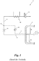
- Fig. 1 shows a tank system according to the prior art in a simplified hydraulic scheme.
- the tank system 1 has a temperature-insulated double-walled cryogenic container 2 in which a two-phase mixture 3 of cryogas 4 and cryogenic liquid 5 is received.
- the less dense cryogenic gas 4 is located substantially in a head region 6 of the container 2, from which head region 6 a first extraction line 7 for cryogas 4 starts, whereas the denser cryogenic liquid 5 collects in a bottom region 8 of the container 2, from which bottom region 8 a second extraction line 9 for Kryockenkeit 5 goes out.
- Both discharge lines 7, 9 open at a junction 10 in a feed line 11.
- the feed line 11 is subsequently passed through a heating element 12, for example a heat exchanger, in which the cryogenic two-phase mixture 3 is evaporated.
- a subsequent to the heating element 12 and thus lying outside the cryogenic range switching valve 13 opens or closes the feed line in the direction of the consumer, such as a vehicle drive.
- the switching valve 13 serves as an automatic shut-off valve and must, like all upstream elements, be specially protected against damage from the outside.
- cryocontainer 2 is under a pressure between about 7 to 10 bar, at which a refueling takes place, and about 16 bar, above which a controlled boil-off over in Fig. 1 not shown safety valves.
- the container pressure in the cryocontainer 2 increases during standstill periods, that is to say without consumption, by about 1 bar per day, for example.
- cryogenic liquid 5 In order to reduce the container pressure rapidly after a longer standstill and thus to minimize evaporation losses as much as possible, it is preferable to remove cryogas 4, since this reduces the container pressure much more rapidly than the removal of cryogenic liquid 5. In the case of low tank pressure and / or high power requirement of the consumer, however, primarily cryogenic liquid 5 should be used be removed.
- a so-called "economizer circuit" is known from the prior art, which provides a pressure relief valve 14 in the first sampling line 7 and a throttle 15 in the second sampling line 9.
- the pressure relief valve 14 opens the first extraction line 7 when the tank pressure exceeds a threshold and therefore primarily cryogenic gas 4 is to be supplied to the consumer, and closes the first extraction line 7 falls below the threshold.
- the throttle 15 reduces the pressure in the second extraction line 9 by, for example, 1 bar in order to give priority to open cryogenic valve 14 at the junction 10 Kryogas 4 and so reduce the pressure vessel.
- a disadvantage of the economizer circuit is that the throttle 15 permanently reduces the pressure in the second extraction line 9, so that the tank pressure ultimately remains higher, for example, by 1 bar than in the feed line. Furthermore, as a result of at least slight admixture of cryogenic liquid 5 in the feed line 11, the reduction of the container pressure is slowed even when priority is taken of cryogas 4.
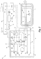
- FIG. 2 shows an embodiment of an inventive tank system 16, eg for the fuel of a vehicle, which can be operated without economizer circuit.
- the tank system 16 comprises a cryocontainer 2, which contains a two-phase mixture 3 of cryogas 4 and cryogenic liquid 5.
- a valve assembly 17 of the tank system 16 Connected to the cryocontainer 2 or at least partially integrated therein is a valve assembly 17 of the tank system 16, which is particularly protected against damage from the outside for use in vehicles - as well as the cryocontainer 2 itself.
- the control panel 18 includes, inter alia, a filler neck 19 with a guided into the cryocontainer 2 filling line 20 with spray nozzle 21 for filling the container 2. For easier filling, the filling line 20 against the Filler 19 locking check valve 22 have.
- a first removal line 7 starts from the head area 6 of the container 2 and removes this cryogas 4.
- the cryogenic liquid 5 collecting in the bottom area 8 of the container 2 is removed by a second removal line 9 emanating there.
- both discharge lines 7, 9 open at a connection 23 in a single, common feed line eleventh
- the feed line 11 leads - optionally backed by a pipe rupture valve 24 - out of the valve assembly 17 and through a heating element 12 through to a consumer M, eg a vehicle drive.
- the heating element 12 heats kryogas 4 or cryogenic liquid 5 in the feed line 11 to approximately normal temperature and thereby completely vaporizes any cryogenic liquid 5.
- the feed line 11 on the consumer side of the heating element 12, a buffer memory 25 and a pressure control valve 26 for uniform, regulated supply of the load M have.
- the tank system 16 also has a valve circuit 27.
- the valve circuit 27 may be, for example, a single 4-way valve or a single 3-way valve, in which latter case the connection 23 is integrated in the 3-way valve.
- the valve circuit 27 comprises two separate controllable switching valves 28, 29, u.zw. a first switching valve 28 which opens the first withdrawal line 7 or at least closes in the direction of the consumer M and a second switching valve 29 which opens the second withdrawal line 9 or closes it at least in the direction of the consumer M.
- the second removal line 9 does not open into the feed line 11, but into a separate feed line, which is guided by a further heating element separate from said heating element 12 and supplies the consumer M, e.g. a vehicle engine, feeds.
- the first extraction line 7 feeds via the feed line 11 and the heating element 12 either a separate consumer, e.g. a parking heater of a vehicle, or the same consumer M as the other feed line.
- the valve circuit 27 assumes the first switching state S 1 when the measured container pressure P 1 is greater than a predetermined first threshold value ⁇ 1 , and the second switching state S 2 when the measured container pressure P 1 is smaller than the first threshold value ⁇ 1 . Due to the exclusive removal of cryogas 4 in the first switching state S 1 , the container pressure P 1 is reduced as quickly as possible, since cryotube 4 has an approximately 600 times lower volumetric energy density compared to cryogenic liquid 5.
- the tank system 16 further comprises a first pressure sensor 30 for measuring the tank pressure P 1 .
- the first pressure sensor 30 is disposed inside the container 2 or outside, according to FIG Fig. 2
- the valve circuit 27 includes a controller 31a, eg a mechanical pressure switch or control electronics, which is connected to the first pressure sensor 30, the container pressure P 1 and its measured values and receives in dependence of which the valve circuit 27 and the first and second switching valve 28, 29 controls.
- Fig. 3b shows, the valve circuit 27 assumes the third switching state S 3 when the measured container pressure P 1 is greater than the first threshold ⁇ 1 and at the same time a consumer-side feed pressure P 2 in the feed line 11 is smaller than a predetermined second threshold ⁇ 2 .
- the tank system 16 may have a second pressure sensor 32 connected to the valve circuit 27 for this purpose.
- the Fig. 3a and 3b illustrate the three switching states S 1 , S 2 , S 3 during operation of the tank system 16, ie when dining the consumer M.
- a first threshold ⁇ 1 exceeding tank pressure P 1 is therefore the cryocontainer 2 exclusively Kryogas 4 removed (first switching state S 1 ).
- the valve circuit 27 additionally opens the second extraction line 9, so in addition kryoironkeit 5 enters the feed line 11 to evaporate in the heating element 12 and the consumer M to be supplied (third switching state S 3 ).
- the container pressure P 1 irrespective of whether it starts from the first switching state S 1 or the third switching state S 3 , falls below the first threshold value ⁇ 1 , then it closes Valve circuit 27, the first extraction line 7 and opens the second extraction line 9 or keeps them open (second switching state S 2 ), and in each case vice versa.
- the said separate consumer is fed by means of the first removal line 7, in which case the first removal line is closed at container pressure P 1 falling below the first threshold value ⁇ 1 (second switching state S 2 ).
- the valve circuit 27 is further between the aforementioned switching states S 1 and S 2 or S 1 , S 2 and S 3 (if provided) and one in the Fig. 3a and 3b not shown state switchable, in which both sampling lines 7, 9 are closed at least in the direction of the consumer M.
- This fourth switching state corresponds to a shutdown of the container 2 together with the valve assembly 17, for example, because the consumer M has no need or for safety reasons in case of damage from the outside, such as an accident of the vehicle.
- the first threshold value ⁇ 1 is, for example, less than 12 bar, preferably less than 10 bar, more preferably between about 7 and about 9 bar, the vessel pressure P 1 as quickly as possible to this level. If the cryocontainer 2 is designed to accommodate another cryogenic two-phase mixture 3, then the first threshold value ⁇ 1 is determined as required.
- the valve circuit 27 for the first and / or the second extraction line 7, 9 also has a check valve 33, 34, which leaves the respective extraction line 7, 9 open when closing in the direction of the consumer M in the direction of the container 2.
- the first switching valve 28 and the second switching valve 29 each have such a check valve 33 or 34 integrated;
- at least one of the check valves 33, 34 could also be arranged in a separate bypass line of the first or second switching valve 28, 29 or the valve circuit 27.
- the second extraction line 9 for example in the bottom region 8 of the container 2 or at another point a pump 35 to cryogenic liquid 5 from the cryocontainer 2, even at low tank pressure P 1 of eg less than about 7 bar safely in the second Extraction line 9 to promote. So that there is no overpressure situation in the second extraction line 9, if this is closed by the valve circuit 27, the second extraction line 9 in the example of Fig. 2
- the overpressure valve 36 is seated in the valve assembly 17, but it could alternatively also be arranged, for example, in the interior of the container 2, and could in each case open into the open; However, the pressure relief valve 36 preferably discharges into a line leading back into the cryocontainer 2, in this case an optional separate drain line 37 of the container 2.
- the drain line 37 connects the bottom portion 8 of the container 2 with the control panel 18, where for manual emptying of the container 2, a manual shut-off valve 38 is provided.
- the first removal line 7 an optional check valve 39, which prevents penetration of the cryogenic liquid 5 into the first withdrawal line 7 and thus short circuit funding from the pump 35 via the second withdrawal line 9, the connection point 23 and the first withdrawal line 7 back into the cryocontainer 2.
- the check valve 39 is seated between connection point 23 and the valve circuit 27 or the first switching valve 28;
- the non-return valve 39 could alternatively also be arranged on the container side of the valve circuit 27 or of the first switching valve 28.
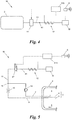
- Fig. 4 shows the general case of the tank system with the cryocontainer 2, which receives the two-phase mixture 3 of cryogas 4 and cryogenic liquid 5, the feed line 11, which the consumer M of at least one extraction line, ie emanating from the cryocontainer 2 first extraction line 7 and / or from Cryo container 2 outgoing second extraction line 9, from feeds, and the heating element 12, through which the feed line 11 is guided.
- the valve circuit 27 is arranged in the feed line 11 or in the at least one extraction line 7, 9, but in any case the container side of the heating element 12.
- the valve circuit 27 is electrically controlled by an electrical control 31b such that it controls the at least one extraction line 7, 9 - ie in the case that both extraction lines 7, 9, in the feed line 11 open, these two extraction lines 7, 9 - or the supply line 11 on or off, thus enabling the food of the consumer M or prevents.
- the controller 31b itself is connected to a sensor, eg a key switch S of an ignition lock or a crash sensor of a vehicle, which influences the controller 31b.
- Fig. 5 shows an embodiment of the tank system 16 with first and second extraction lines 7, 9, which as in the example of Fig. 1 form with pressure relief valve 14 and throttle 15 an economizer circuit, where, however, contrary Fig. 1 the valve circuit 27 - formed here as a single electromagnetic switching valve - container side of the heating element 12 is arranged in the feed line 11.
- valve circuit 27 or switching valves 28, 29 are arranged in the first and / or second withdrawal line, and further switching states S 1 , S 2 and / or S 3 as a function of container pressure P 1 and / or feed pressure P 2 , were mentioned above in connection with the Fig. 2 . 3a and 3b explained in detail.
- Fig. 6a and 6b For example, two or more tank systems 1, 16 can be grouped together and feed a consumer M together. Since according to the prior art ( Fig. 4a ) the heating element 12 must be arranged according to the guideline ECE R110 for vehicles within the protected area of the shut-off valves 13, in the prior art is an interconnection of two tank systems 1 only in the normal temperature range, ie Consumer side of the heating elements 12 possible, which requires multiple heating elements 12.
- valve circuit 27 of the tank system 16 according to the invention allows a protective shutdown already in the cryogenic region, so that two or more tank systems 16 according to the invention are combined to form a plant 40 at a merger point 41, which is the container side of the heating element 12.
- the so-combined feed lines 11 can thus be performed over a single common heating element 12.
- the tank system 16 may have other components, such as Fig. 2 exemplifies.
- the container pressure P 1 if desired, can be output on a display 42, for example on the control console 18.
- the feed line 11 can have an eg manual shut-off valve 43 on the operating console 18.
- an optional vent line 44 with connection piece 46 and shut-off valve 45 could be guided into the control console 18.
- an exhaust steam valve 47 which opens at 16 bar when using LNG, for example at a tank pressure P 1
- an emergency exhaust valve 48 which opens at 22 bar, for example, in a tank pressure P 1 , for example in the first extraction line. 7 be provided.
- the heating element 12 may each be a heat exchanger, which is fed via a connecting rail 49 of the tank system 16 with waste heat from the vehicle engine.
- the connecting rail 49 may further support a connecting piece 50 for connecting the load M, eg vehicle engine, to the feed line 11.
- the exhaust steam and / or Notabdampfventile 47, 48 can be connected via the connecting rail 49 to an exhaust line (Vent Stack) 51 of the vehicle.
- An engine control unit (ECU) 52 of the vehicle may be connected via the connection rail 49 to the tank system 16, the valve assembly 17 and the valve circuit 27, for example with a level sensor 53 in the cryocontainer 2, the valve circuit 27, the first and second Switching valve 28, 29 and / or the first and second pressure sensor 30, 32nd
- the engine controller 52 may also assume control of the first and second switching valves 28, 29 and the valve circuit 27, respectively.
- the electric controller 31b and / or the controller 31a of the valve circuit 27 may be part of the engine controller 52.
Description
Die vorliegende Erfindung betrifft ein Tanksystem gemäß dem Oberbegriff des Anspruchs 1. Die Erfindung betrifft ferner eine Anlage mit zumindest zwei solchen Tanksystemen.The present invention relates to a tank system according to the preamble of
Ein Tanksystem der im Oberbegriff des Anspruchs 1 genannten Art ist in der älteren, nicht vorveröffentlichten Anmeldung
Um den Energiegehalt von Energieträgern, welche unter Normalbedingungen gasförmig sind, zu erhöhen, werden diese für Transport- und Lagerungszwecke entweder komprimiert und in einem Druckbehälter gespeichert oder auf Tieftemperatur abgekühlt, dabei verflüssigt und in temperaturisolierten Behältern, sogenannten Kryobehältern, gespeichert. So werden beispielsweise zum Antrieb von Fahrzeugen verflüssigtes Erdgas (Liquefied Natural Gas, LNG) oder verflüssigter Wasserstoff als Zweiphasengemisch mit hoher Energiedichte gespeichert, um hinterher beispielsweise zum Betrieb von Verbrennungskraftmaschinen oder Brennstoffzellen der Fahrzeuge genutzt zu werden.In order to increase the energy content of energy carriers, which are gaseous under normal conditions, they are either compressed for transport and storage purposes and stored in a pressure vessel or cooled to cryogenic temperature, thereby liquefied and stored in temperature-insulated containers, so-called cryogenic containers. For example, to drive vehicles liquefied natural gas (LNG) or liquefied hydrogen are stored as a two-phase mixture with high energy density to be subsequently used, for example, to operate internal combustion engines or fuel cells of the vehicles.
Aus Sicherheitsgründen ist es erforderlich, die den Verbraucher speisende Speiseleitung mit einem Abschaltventil schließen zu können. Je nach Anwendung ist es dabei vielfach auch vorgeschrieben, alle Komponenten, welche behälterseitig des Abschaltventils angeordnet sind, sowie das Abschaltventil selbst und den Kryobehälter gegen Beschädigungen von außen zu schützen. Beispielsweise ist bei der Verwendung des Tanksystems in Kraftfahrzeugen gemäß der Richtlinie ECE R110 ein Abschaltventil vorgeschrieben, welches zusammen mit dem Kryobehälter innerhalb des gegen Beschädigungen von außen geschützten Bereichs zu liegen hat und diesen Bereich gegenüber allen außenliegenden Komponenten und Verbrauchern z.B. im Falle einer solchen Beschädigung bzw. vorsorglich beim Abschalten des Fahrzeugantriebs abschaltet. Diese Notwendigkeit, einen gegen Beschädigung besonders geschützten Bereich zur Aufnahme der genannten Komponenten auszubilden, schränkt die Flexibilität in Aufbau und Anwendung der Tanksysteme ein, umso mehr, je größer der geschützte Bereich auszubilden ist, d.h. je mehr Komponenten zu schützen sind.For safety reasons, it is necessary to be able to close the feed line feeding the load with a shut-off valve. Depending on the application, it is often prescribed to protect all components which are arranged on the container side of the shut-off valve, as well as the shut-off valve itself and the cryocontainer against damage from the outside. For example, when using the fuel tank system in accordance with the ECE directive R110, a shut-off valve is provided prescribed, which has to lie together with the cryocontainer within the area protected against damage from the outside and this area with respect to all external components and consumers, for example in the event of such damage or as a precaution when switching off the vehicle drive off. This requirement to form a particularly protected against damage area for receiving said components, limits the flexibility in design and application of the tank systems, the more, the larger the protected area is to be formed, ie the more components are to be protected.
Die vorliegende Erfindung setzt sich zum Ziel, ein Tanksystem und eine Anlage zu schaffen, welche besonders flexibel einsetzbar sind.The present invention sets itself the goal of creating a tank system and a system which can be used particularly flexibly.
Gemäß einem ersten Aspekt der Erfindung wird dieses Ziel mit einem Tanksystem der einleitend genannten Art erreicht, welches sich dadurch auszeichnet, dass die Ventilschaltung für die erste Entnahmeleitung ein Rückschlagventil hat, welches diese bei Schließen in Richtung des Verbrauchers in Richtung des Behälters geöffnet lässt, und/oder dass die Ventilschaltung für die zweite Entnahmeleitung ein Rückschlagventil hat, welches diese bei Schließen in Richtung des Verbrauchers in Richtung des Behälters geöffnet lässt.According to a first aspect of the invention, this object is achieved with a tank system of the aforementioned type, which is characterized in that the valve circuit for the first extraction line has a check valve, which leaves open when closing in the direction of the consumer in the direction of the container, and or that the valve circuit for the second extraction line has a check valve, which leaves open when closing in the direction of the consumer in the direction of the container.
Entgegen herkömmlichen Tanksystemen, bei welchen die Ventilschaltung verbraucherseits des Heizelements sitzt und folglich das Heizelement in den geschützten Bereich aufgenommen werden muss, erlaubt die neuartige Anordnung der Ventilschaltung, das Heizelement außerhalb dieses geschützten Bereichs anzuordnen, was den Aufbau des Tanksystems wesentlich vereinfacht und die Zahl und Größe der zu schützenden Komponenten wesentlich reduziert, sodass auch der geschützte Bereich kleiner ausgeführt werden kann. Im vorliegenden Fall kann ferner ein zusätzliches, verbraucherseits des Heizelements liegendes Abschaltventil entfallen, da das Speisen des Verbrauchers völlig unterbunden werden kann. Dadurch, dass die Ventilschaltung für die zweite Entnahmeleitung ein Rückschlagventil hat, welches diese bei Schließen in Richtung des Verbrauchers in Richtung des Behälters geöffnet lässt, und/oder dass die Ventilschaltung für die erste Entnahmeleitung ein Rückschlagventil hat, welches diese bei Schließen in Richtung des Verbrauchers in Richtung des Behälters geöffnet lässt, kann ein Überdruck in der Speiseleitung, wenn sich diese z.B. während einer Stehzeit erwärmt, durch Rückfluss in den Kryobehälter abgebaut werden, was die Speiseleitung schützt und zugleich Abdampfverluste weiter verringert.Contrary to conventional tank systems in which the valve circuit sits on the consumer side of the heating element and consequently the heating element has to be accommodated in the protected area, the novel arrangement of the valve circuit allows To arrange the heating element outside this protected area, which greatly simplifies the construction of the tank system and significantly reduces the number and size of the components to be protected, so that the protected area can be made smaller. Furthermore, in the present case, an additional shut-off valve located on the consumer side of the heating element can be dispensed with, because the food supply to the consumer can be completely prevented. Characterized in that the valve circuit for the second withdrawal line has a check valve, which leaves open when closing in the direction of the consumer in the direction of the container, and / or that the valve circuit for the first withdrawal line has a check valve, which when closing in the direction of the consumer open in the direction of the container, an overpressure in the feed line, if this is heated, for example, for a while, be reduced by reflux in the cryocontainer, which protects the feed line and at the same time further reduces Abdampfverluste.
Bevorzugt hat das Tanksystem eine von einem Kopfbereich des Kryobehälters ausgehende erste Entnahmeleitung für Kryogas, welche in die genannte Speiseleitung mündet. Dadurch kann, z.B. bei hohem Behälterdruck, dem Kryobehälter gezielt Kryogas entnommen werden. Wenn alternativ oder ergänzend dem Kryobehälter gezielt Kryoflüssigkeit entnommen werden soll, so ist es günstig, wenn das Tanksystem eine von einem Bodenbereich des Kryobehälters ausgehende zweite Entnahmeleitung für Kryoflüssigkeit hat, welche in die genannte Speiseleitung mündet.The tank system preferably has a first removal line for cryogas emanating from a head region of the cryocontainer, which discharges into the said feed line. This allows, for example, at high container pressure, the cryocontainer specifically kryogas be removed. If, alternatively or additionally, cryogenic liquid is to be removed selectively from the cryocontainer, then it is favorable if the tank system has a second removal line for cryogenic liquid emanating from a bottom region of the cryocontainer, which empties into the named feed line.
Gemäß einer besonders bevorzugten Ausführungsform hat der Kryobehälter einen ersten Drucksensor zum Messen des Behälterdrucks, an welchen die Ventilschaltung angeschlossen ist, wobei die Ventilschaltung zumindest zwischen dem genannten abgeschalteten Zustand, einem ersten Schaltzustand, in welchem die erste Entnahmeleitung geöffnet und die zweite Entnahmeleitung zumindest in Richtung des Verbrauchers geschlossen ist, und einem zweiten Schaltzustand, in welchem die erste Entnahmeleitung zumindest in Richtung des Verbrauchers geschlossen und die zweite Entnahmeleitung geöffnet ist, umschaltbar ist, und wobei die Ventilschaltung den ersten Schaltzustand einnimmt, wenn der gemessene Behälterdruck größer als ein vorgegebener erster Schwellwert ist, und den zweiten Schaltzustand einnimmt, wenn der gemessene Behälterdruck kleiner als der erste Schwellwert ist.According to a particularly preferred embodiment, the cryocontainer has a first pressure sensor for measuring the container pressure to which the valve circuit is connected, wherein the valve circuit at least between said off state, a first switching state in which the first extraction line open and the second extraction line at least in the direction is closed, and wherein the valve circuit assumes the first switching state, when the measured container pressure greater than a predetermined first threshold is, and assumes the second switching state when the measured container pressure is less than the first threshold value.
Auf diese Weise kann je nach Behälterdruck ausschließlich Kryogas oder ausschließlich Kryoflüssigkeit dem Kryobehälter entnommen werden. Da trotz Isolation des Kryobehälters ein Temperatureintrag von außen in den Kryobehälter nicht gänzlich verhindert werden kann, steigt z.B. während Stehzeiten, d.h ohne Verbrauch, der Behälterdruck um beispielsweise etwa 1 bar pro Tag. Durch reine Kryogas-Entnahme im ersten Schaltzustand wird der Behälterdruck raschest möglich abgebaut. Das ermöglicht längere Stehzeiten des Tanksystems auch bei nur kurzer Betriebsdauer des Verbrauchers und somit geringere Abdampfverluste als mit einem herkömmlichen Tanksystem. Andererseits wird im zweiten Schaltzustand bei schwellwertunterschreitendem Behälterdruck dem Kryobehälter reine Kryoflüssigkeit mit wesentlich höherer Energiedichte entnommen und der Behälterdruck dadurch nur minimal verändert.In this way, depending on the container pressure only cryogas or only cryogenic liquid can be removed from the cryocontainer. Since, despite the isolation of the cryocontainer, a temperature entry from the outside into the cryocontainer can not be completely prevented, for example during standstill times, ie without consumption, the container pressure increases by, for example, about 1 bar per day. By pure Kryogas removal in the first switching state of the container pressure is reduced as quickly as possible. This allows longer standstill of the tank system even with a short operating time of the consumer and thus lower evaporation losses than with a conventional tank system. On the other hand, in the second switching state at Schwellwertunterschreitendem tank pressure the cryocontainer pure Kryoflüssigkeit removed with much higher energy density and the container pressure thereby changed only minimally.
Ein besonders einfacher Aufbau des Tanksystems ergibt sich, wenn die Ventilschaltung ein die erste Entnahmeleitung öffnendes und zumindest in Richtung des Verbrauchers schließendes erstes steuerbares Schaltventil und ein davon separates die zweite Entnahmeleitung öffnendes und zumindest in Richtung des Verbrauchers schließendes zweites steuerbares Schaltventil umfasst. Dabei werden insbesondere kryotaugliche 2-Wege-Schaltventile mit je zwei Schaltzuständen eingesetzt. Bevorzugt sind dabei die Schaltventile elektromagnetische Schaltventile, welche besonders einfach und zuverlässig steuerbar sind und so einen flexiblen Einsatz des Tanksystems erlauben.A particularly simple construction of the tank system results when the valve circuit comprises a first controllable switching valve opening the first withdrawal line and closing at least in the direction of the consumer and a separate second controllable switching valve opening the second withdrawal line and closing at least in the direction of the consumer. In particular, cryogenic 2-way switching valves are used, each with two switching states. In this case, the switching valves are preferably electromagnetic switching valves, which are particularly simple and reliable controllable and thus allow flexible use of the tank system.
In einer besonders vorteilhaften Variante umfasst das Tanksystem ferner einen mit der Ventilschaltung verbundenen zweiten Drucksensor zum Messen eines verbraucherseitigen Speisedrucks der Speiseleitung, wobei die Ventilschaltung zwischen zwischen dem genannten abgeschalteten Zustand, den genannten Schaltzuständen und einem dritten Schaltzustand umschaltbar ist, in welchem beide Entnahmeleitungen geöffnet sind, und wobei die Ventilschaltung den dritten Schaltzustand einnimmt, wenn der gemessene Behälterdruck größer als der erste Schwellwert und zugleich der gemessene Speisedruck kleiner als ein vorgegebener zweiter Schwellwert ist. Aufgrund der wesentlich höheren volumetrischen Energiedichte der Kryogflüssigkeit im Vergleich zum Kryogas - bei Flüssigerdgas typisch etwa 600 mal höher - kann somit bei zu geringem bzw. sinkendem Speisedruck infolge erhöhter Abnahme des Verbrauchers der Speisedruck wieder rasch erhöht werden, wobei dennoch der Behälterdruck aufgrund der zusätzlichen Entnahme von Kryogas abgebaut wird.In a particularly advantageous variant, the tank system further comprises a second pressure sensor connected to the valve circuit for measuring a consumer-side feed pressure of the feed line, wherein the valve circuit is switchable between between said off state, said switching states and a third switching state in which both sampling lines are open , and wherein the valve circuit assumes the third switching state when the measured container pressure is greater than the first threshold value and at the same time the measured feed pressure is less than a predetermined second threshold value. Due to the significantly higher volumetric energy density of the cryogenic liquid compared to the cryogenic gas - with liquefied natural gas typically about 600 times higher - can thus be increased rapidly at too low or falling feed pressure due to increased decrease in the consumer, the feed pressure again, yet the container pressure is reduced due to the additional removal of kryogas.
Um einen raschen Abbau des Behälterdrucks bis zu einem niedrigen Niveau sicherzustellen, ist es vorteilhaft, wenn der erste Schwellwert kleiner als 12 bar, bevorzugt kleiner als 10 bar, besonders bevorzugt zwischen etwa 7 bar und etwa 9 bar ist.In order to ensure a rapid reduction of the container pressure to a low level, it is advantageous if the first threshold value is less than 12 bar, preferably less than 10 bar, more preferably between about 7 bar and about 9 bar.
Bevorzugt hat die zweite Entnahmeleitung eine Pumpe für Kryoflüssigkeit. Dies stellt die Entnahme von Kryoflüssigkeit völlig unabhängig vom Behälterdruck sicher, d.h. auch bei einem Behälterdruck von mehr als etwa 12 bar oder insbesondere weniger als etwa 7 bar.Preferably, the second extraction line has a pump for cryogenic liquid. This ensures the removal of cryogenic liquid completely independent of container pressure, i. even at a tank pressure of more than about 12 bar or more preferably less than about 7 bar.
In einem zweiten Aspekt schafft die Erfindung eine Anlage mit zumindest zwei Tanksystemen der beschriebenen Art, wobei die Speiseleitungen der Tanksysteme vereinigt über ein einziges gemeinsames Heizelement geführt sind. Weitere Heizelemente können dadurch entfallen; die Anlage ist somit einfacher im Aufbau. Ferner kann durch geeignete Steuerung der Ventilschaltung der Tanksysteme ein Druckabbau in jedem der Tanksysteme bewerkstelligt werden, sodass z.B. Druckunterschiede ausgeglichen werden.In a second aspect, the invention provides a system with at least two tank systems of the type described, wherein the feed lines of the tank systems combined are guided over a single common heating element. Other heating elements can be omitted; The system is thus simpler in construction. Further, by appropriate control of the valve circuitry of the tank systems, pressure reduction in each of the tank systems can be accomplished, e.g. Pressure differences are compensated.
Bezüglich weiterer Vorteile und Ausführungsvarianten einer solchen Anlage wird auf die vorangegangenen Ausführungen zum Tanksystem verwiesen.With regard to further advantages and variants of such a system, reference is made to the preceding comments on the tank system.
Die Erfindung wird nachfolgend anhand von in den beigeschlossenen Zeichnungen dargestellten Ausführungsbeispielen näher erläutert. In den Zeichnungen zeigen:
-
Fig. 1 ein Tanksystem gemäß dem Stand der Technik in Form eines vereinfachten Hydraulikschemas; -
Fig. 2 eine Ausführungsvariante eines Tanksystems gemäß der Erfindung in Form eines Hydraulikschemas; - die
Fig. 3a und 3b verschiedene Schaltzustände einer Ventilschaltung des Tanksystems ausFig. 2 in einem Zustandsdiagramm (Fig. 3a ) bzw. einem Druckdiagramm (Fig. 3b ); -
Fig. 4 eine allgemeine Ausführungsform des Tanksystems gemäß der Erfindung in Form eines vereinfachten Hydraulikschemas; -
Fig. 5 eine Variante des Tanksystems vonFig. 4 in Form eines vereinfachten Hydraulikschemas; und - die
Fig. 6a und 6b jeweils eine Anlage mit zwei Tanksystemen gemäß dem Stand der Technik (Fig. 6a ) bzw. gemäß der vorliegenden Erfindung (Fig. 6b ).
-
Fig. 1 a tank system according to the prior art in the form of a simplified hydraulic scheme; -
Fig. 2 an embodiment of a tank system according to the invention in the form of a hydraulic scheme; - the
Fig. 3a and 3b different switching states of a valve circuit of the tank systemFig. 2 in a state diagram (Fig. 3a ) or a pressure diagram (Fig. 3b ); -
Fig. 4 a general embodiment of the tank system according to the invention in the form of a simplified hydraulic scheme; -
Fig. 5 a variant of the tank system ofFig. 4 in the form of a simplified hydraulic scheme; and - the
Fig. 6a and 6b one plant each with two tank systems according to the prior art (Fig. 6a ) or according to the present invention (Fig. 6b ).
Im Falle von Flüssigerdgas steht der Kryobehälter 2 unter einem Druck zwischen etwa 7 bis 10 bar, bei welchem ein Betanken erfolgt, und etwa 16 bar, oberhalb dessen ein kontrolliertes Abdampfen ("boil-off") über in
Da trotz Isolation des Behälters 2 ein Temperatureintrag von außen in den Kryobehälter 2 nicht gänzlich verhindert werden kann, steigt während Stehzeiten, d.h ohne Verbrauch, der Behälterdruck im Kryobehälter 2 um beispielsweise etwa 1 bar pro Tag.Since, in spite of insulation of the
Um nach längerer Stehzeit den Behälterdruck rasch abzusenken und so Abdampfverluste möglichst gering zu halten, soll vorrangig Kryogas 4 entnommen werden, da dies den Behälterdruck wesentlich rascher als die Entnahme von Kryoflüssigkeit 5 reduziert. Bei niedrigem Behälterdruck und/oder großem Leistungsbedarf des Verbrauchers soll hingegen vorrangig Kryoflüssigkeit 5 entnommen werden. Dazu ist aus dem Stand der Technik eine sogenannte "Economizer-Schaltung" bekannt, welche in der ersten Entnahmeleitung 7 ein Überdruckventil 14 und in der zweiten Entnahmeleitung 9 eine Drossel 15 vorsieht. Das Überdruckventil 14 öffnet die erste Entnahmeleitung 7, wenn der Behälterdruck einen Schwellwert überschreitet und deshalb vorrangig Kryogas 4 dem Verbraucher zugeführt werden soll, und schließt die erste Entnahmeleitung 7 bei Unterschreiten des Schwellwerts. Die Drossel 15 reduziert den Druck in der zweiten Entnahmeleitung 9 um beispielsweise 1 bar, um bei geöffnetem Überdruckventil 14 an der Einmündung 10 Kryogas 4 den Vorrang zu geben und so den Behälterdruck abzubauen.In order to reduce the container pressure rapidly after a longer standstill and thus to minimize evaporation losses as much as possible, it is preferable to remove
Nachteilig an der Economizer-Schaltung ist jedoch, dass die Drossel 15 dauerhaft den Druck in der zweiten Entnahmeleitung 9 reduziert, sodass der Behälterdruck letztlich um beispielsweise 1 bar höher als in der Speiseleitung bleibt. Ferner wird infolge zumindest geringfügiger Beimengung von Kryoflüssigkeit 5 in die Speiseleitung 11 auch bei vorrangiger Entnahme von Kryogas 4 der Abbau des Behälterdrucks verlangsamt.A disadvantage of the economizer circuit, however, is that the
Die
Im Beispiel der
Eine erste Entnahmeleitung 7 geht vom Kopfbereich 6 des Behälters 2 aus und entnimmt diesem Kryogas 4. Die sich im Bodenbereich 8 des Behälters 2 sammelnde Kryoflüssigkeit 5 wird von einer dort ausgehenden zweiten Entnahmeleitung 9 entnommen. In der in
Die Speiseleitung 11 gemäß
Zur gezielten Entnahme von Kryogas 4 und/oder Kryoflüssigkeit 5 aus dem Kryobehälter 2 hat das Tanksystem 16 ferner eine Ventilschaltung 27. Die Ventilschaltung 27 kann z.B. ein einziges 4-Wege-Ventil oder ein einziges 3-Wege-Ventil sein, in welchem letzteren Fall die Verbindung 23 in das 3-Wege-Ventil integriert ist. Im Beispiel von
In einer alternativen Variante (nicht dargestellt) mündet die zweite Entnahmeleitung 9 nicht in die Speiseleitung 11, sondern in eine von dieser separate weitere Speiseleitung, welche durch ein vom genannten Heizelement 12 separates weiteres Heizelement geführt ist und den Verbraucher M, z.B. einen Fahrzeugmotor, speist. Die erste Entnahmeleitung 7 speist dabei über die Speiseleitung 11 und das Heizelement 12 entweder einen separaten Verbraucher, z.B. eine Standheizung eines Fahrzeugs, oder denselben Verbraucher M wie die weitere Speiseleitung.In an alternative variant (not shown), the
Gemäß den
Um das Umschalten zwischen erstem und zweitem Schaltzustand S1, S2 auch ohne Benutzereingriff zu ermöglichen, umfasst das Tanksystem 16 ferner einen ersten Drucksensor 30 zum Messen des Behälterdrucks P1. Der erste Drucksensor 30 ist im Inneren des Behälters 2 oder außerhalb angeordnet, gemäß
Optional ist die Ventilschaltung 27 zwischen den genannten Schaltzuständen S1, S2 und einem dritten Schaltzustand S3 umschaltbar, in welchem dritten Schaltzustand S3 beide Entnahmeleitungen 7, 9 geöffnet (V1 = 1; V2 = 1) sind. Wie
Die
Die Ventilschaltung 27 ist ferner zwischen den genannten Schaltzuständen S1 und S2 bzw. S1, S2 und S3 (wenn vorgesehen) und einem in den
Wird das Tanksystem 16 für verflüssigtes Erdgas (Liquefied Natural Gas, LNG) eingesetzt, so ist der erste Schwellwert σ1 z.B. kleiner als 12 bar, bevorzugt kleiner als 10 bar, besonders bevorzugt zwischen etwa 7 und etwa 9 bar, um den Behälterdruck P1 möglichst rasch auf dieses Niveau zu senken. Ist der Kryobehälter 2 zur Aufnahme eines anderen kryogenen Zweiphasengemischs 3 ausgebildet, so wird der erste Schwellwert σ1 nach Bedarf festgelegt.If the
Optional hat die Ventilschaltung 27 für die erste und/oder die zweite Entnahmeleitung 7, 9 ferner ein Rückschlagventil 33, 34, welches die jeweilige Entnahmeleitung 7, 9 beim Schließen in Richtung des Verbrauchers M in Richtung des Behälters 2 geöffnet lässt. Dadurch wird eine mögliche Druckerhöhung in der Speiseleitung 11, z.B. während Stehzeiten, ohne Abdampfverlust in den Kryobehälter 2 rückgespeist. Im Beispiel der
In einer weiteren optionalen Variante hat die zweite Entnahmeleitung 9 z.B. im Bodenbereich 8 des Behälters 2 oder an einer anderen Stelle eine Pumpe 35, um Kryoflüssigkeit 5 aus dem Kryobehälter 2 auch bei geringem Behälterdruck P1 von z.B. weniger als etwa 7 bar sicher in die zweite Entnahmeleitung 9 zu fördern. Damit es dabei zu keiner Überdrucksituation in der zweiten Entnahmeleitung 9 kommt, falls diese durch die Ventilschaltung 27 geschlossen ist, hat die zweite Entnahmeleitung 9 im Beispiel der
Ferner hat dabei in der Ausführungsform nach
Alternative Varianten, wonach die Ventilschaltung 27 bzw. Schaltventile 28, 29 in der ersten und/oder zweiten Entnahmeleitung angeordnet sind, und weitere Schaltzustände S1, S2 und/oder S3 in Abhängigkeit von Behälterdruck P1 und/oder Speisedruck P2, wurden vorstehend im Zusammenhang mit den
Gemäß den
Im Gegensatz dazu ermöglicht die Ventilschaltung 27 des erfindungsgemäßen Tanksystems 16 eine Schutzabschaltung bereits im kryogenen Bereich, sodass zwei oder mehr erfindungsgemäße Tanksysteme 16 zu einer Anlage 40 an einem Zusammenführungspunkt 41 vereinigt werden, welcher behälterseits des Heizelements 12 liegt. Die so vereinigten Speiseleitungen 11 können damit über ein einziges gemeinsames Heizelement 12 geführt werden.In contrast, the
Es versteht sich, dass das Tanksystem 16 über weitere Komponenten verfügen kann, wie
Aus Sicherheitsgründen können ferner ein Abdampfventil 47, welches bei Verwendung von LNG beispielsweise bei einem Behälterdruck P1 von 16 bar öffnet, und optional ein Not-Abdampfventil 48, welches beispielsweise bei einem Behälterdruck P1 von 22 bar öffnet, z.B. in der ersten Entnahmeleitung 7 vorgesehen sein.For safety reasons, furthermore, an
Das Heizelement 12 kann jeweils ein Wärmetauscher sein, welcher über eine Anschlussschiene 49 des Tanksystems 16 mit Abwärme vom Fahrzeugmotor gespeist wird. Die Anschlussschiene 49 kann ferner einen Anschlussstutzen 50 zum Anschließen des Verbrauchers M, z.B. Fahrzeugmotors, an die Speiseleitung 11 abstützen. Auch können die Abdampf- und/oder Notabdampfventile 47, 48 über die Anschlussschiene 49 an einen Abgasstrang (Vent Stack) 51 des Fahrzeugs angeschlossen werden.The
Eine Motorsteuerung (Engine Control Unit, ECU) 52 des Fahrzeugs kann über die Anschlussschiene 49 mit dem Tanksystem 16, der Ventilbaugruppe 17 bzw. der Ventilschaltung 27 verbunden sein, beispielsweise mit einem Füllstandssensor 53 im Kryobehälter 2, der Ventilschaltung 27, dem ersten und zweiten Schaltventil 28, 29 und/oder dem ersten und zweiten Drucksensor 30, 32.An engine control unit (ECU) 52 of the vehicle may be connected via the
Die Motorsteuerung 52 kann auch die Steuerung des ersten und zweiten Schaltventils 28, 29 bzw. der Ventilschaltung 27 übernehmen, d.h. die elektrische Steuerung 31b und/oder die Steuerung 31a der Ventilschaltung 27 können ein Teil der Motorsteuerung 52 sein.The
Die Erfindung ist nicht auf die dargestellten Ausführungsformen beschränkt, sondern umfasst alle Varianten, Kombinationen und Modifikationen, die in den Rahmen der angeschlossenen Ansprüche fallen.The invention is not limited to the illustrated embodiments, but includes all variants, combinations and modifications that fall within the scope of the appended claims.
Claims (8)
- Tank system, comprising
a cryogenic vessel (2) for receiving a two-phase mixture (3) of cryogenic gas (4) and cryogenic liquid (5),
a feed line (11) for feeding a consumer (M) from at least one extraction line (7, 9) outgoing from the cryogenic vessel (2),
a heating element (12) through which the feed line (11) passes,
an electronically controllable valve circuit (27) for controlled turning on and off the feeding of the consumer (M),
an electronic control (31b) controlling the valve circuit (27),
a first extraction line (7) outgoing from a top region (6) of the vessel (2) for cryogenic gas (4) and leading into said feed line, and
a second extraction line (9) outgoing from a bottom region (8) of the vessel (2) for cryogenic liquid (5) and leading into said feed line,
wherein the valve circuit (27) is located between the cryogenic vessel (2) and the heating element (12),
characterised in that the valve circuit (27) has a check valve (33) for the first extraction line (7), which check valve (33) leaves the first extraction line (7) open in the direction of the vessel (2) when closing in the direction of the consumer (M), and/or
in that the valve circuit (27) has a check valve (34) for the second extraction line (9), which check valve (34) leaves the second extraction line (9) open in the direction of the vessel (2) when closing in the direction of the consumer (M). - Tank system according to claim 1, characterised in that the cryogenic vessel (2) has a first pressure sensor (30) for measuring the vessel pressure (P1), to which the valve circuit (27) is connected,
wherein the valve circuit (27) is switchable at least between said turned off state, a first switching state (S1), in which the first extraction line (7) is open and the second extraction line (9) is closed at least in the direction of the consumer (M), and a second switching state (S2), in which the first extraction line (7) is closed at least in the direction of the consumer (M) and the second extraction line (9) is open, and
wherein the valve circuit (27) is in the first switching state (S1) when the measured vessel pressure (P1) is greater than a predetermined first threshold (σ1), and is in the second switching state (S2) when the measured vessel pressure (P1) is less than the first threshold (σ1). - Tank system according to claim 2, characterised in that the valve circuit (27) comprises a first controllable switch valve (28) opening the first extraction line (7) and closing it at least in the direction of the consumer (M) and a second controllable switch valve (29) separate therefrom opening the second extraction line (9) and closing it at least in the direction of the consumer (M).
- Tank system according to claim 3, characterised in that the switch valves (28, 29) are electromagnetic switch valves (28, 29).
- Tank system according to any one of the claims 2 to 4, characterised by a second pressure sensor (32) connected to the valve circuit (27) for measuring a consumer-side feeding pressure (P2) of the feed line (11),
wherein the valve circuit (27) is switchable between said turned off state, said switching states (S1, S2), and a third switching state (S3) in which both extraction lines (7, 9) are open, and
wherein the valve circuit (27) is in the third switching state (S3) when the measured vessel pressure (P1) is greater than the first threshold (σ1) and at the same time the measured feeding pressure (P2) is less than a predetermined second threshold (σ2). - Tank system according to any one of the claims 2 to 5, characterised in that the first threshold (σ1) is less than 12 bar, preferably less than 10 bar, particularly preferably between approximately 7 bar and approximately 9 bar.
- Tank system according to any one of the claims 1 to 6, characterised in that the second extraction line (9) has a pump (35) for cryogenic liquid (5).
- Arrangement with at least two tank systems according to any one of the claims 1 to 7, characterised in that the feed lines (11) of the tank systems (16) pass jointly a single common heating element (12).
Priority Applications (7)
| Application Number | Priority Date | Filing Date | Title |
|---|---|---|---|
| PT161667381T PT3236133T (en) | 2016-04-22 | 2016-04-22 | Tank system |
| ES16166738T ES2770673T3 (en) | 2016-04-22 | 2016-04-22 | Tank system |
| PL16166738T PL3236133T3 (en) | 2016-04-22 | 2016-04-22 | Tank system |
| RS20191699A RS59753B1 (en) | 2016-04-22 | 2016-04-22 | Tank system |
| HUE16166738A HUE047498T2 (en) | 2016-04-22 | 2016-04-22 | Tank system |
| EP16166738.1A EP3236133B1 (en) | 2016-04-22 | 2016-04-22 | Tank system |
| SI201630608T SI3236133T1 (en) | 2016-04-22 | 2016-04-22 | Tank system |
Applications Claiming Priority (1)
| Application Number | Priority Date | Filing Date | Title |
|---|---|---|---|
| EP16166738.1A EP3236133B1 (en) | 2016-04-22 | 2016-04-22 | Tank system |
Publications (2)
| Publication Number | Publication Date |
|---|---|
| EP3236133A1 EP3236133A1 (en) | 2017-10-25 |
| EP3236133B1 true EP3236133B1 (en) | 2019-11-13 |
Family
ID=55809000
Family Applications (1)
| Application Number | Title | Priority Date | Filing Date |
|---|---|---|---|
| EP16166738.1A Active EP3236133B1 (en) | 2016-04-22 | 2016-04-22 | Tank system |
Country Status (7)
| Country | Link |
|---|---|
| EP (1) | EP3236133B1 (en) |
| ES (1) | ES2770673T3 (en) |
| HU (1) | HUE047498T2 (en) |
| PL (1) | PL3236133T3 (en) |
| PT (1) | PT3236133T (en) |
| RS (1) | RS59753B1 (en) |
| SI (1) | SI3236133T1 (en) |
Families Citing this family (4)
| Publication number | Priority date | Publication date | Assignee | Title |
|---|---|---|---|---|
| ES2967317T3 (en) * | 2017-11-23 | 2024-04-29 | Salzburger Aluminium Ag | Tank system for a low floor vehicle |
| PT3489062T (en) * | 2017-11-23 | 2020-09-07 | Salzburger Aluminium Ag | Tank system for a low-platform railway truck |
| FR3094070B1 (en) * | 2019-03-21 | 2021-10-15 | Air Liquide | A device and method for storing and supplying fluid fuel. |
| US20230003344A1 (en) * | 2019-11-29 | 2023-01-05 | Cryoshelter Gmbh | A system having at least two cryogenic containers for providing a fluid |
Citations (1)
| Publication number | Priority date | Publication date | Assignee | Title |
|---|---|---|---|---|
| WO2016172803A1 (en) * | 2015-04-30 | 2016-11-03 | Westport Power Inc. | Intelligent pressure management system for cryogenic fluid systems |
Family Cites Families (3)
| Publication number | Priority date | Publication date | Assignee | Title |
|---|---|---|---|---|
| CN201186605Y (en) * | 2008-04-07 | 2009-01-28 | 山东绿能燃气实业有限责任公司 | Liquefied natural gas automobile double tank and multi-tank gas supply system |
| DE102011117158B4 (en) * | 2011-10-28 | 2016-08-11 | Magna Steyr Fahrzeugtechnik Ag & Co. Kg | Tank system for a motor vehicle and operating method therefor |
| CA2833619C (en) * | 2013-11-21 | 2020-06-30 | Westport Power Inc. | Method and system for delivering a gaseous fuel into the air intake system of an internal combustion engine |
-
2016
- 2016-04-22 ES ES16166738T patent/ES2770673T3/en active Active
- 2016-04-22 PL PL16166738T patent/PL3236133T3/en unknown
- 2016-04-22 SI SI201630608T patent/SI3236133T1/en unknown
- 2016-04-22 RS RS20191699A patent/RS59753B1/en unknown
- 2016-04-22 HU HUE16166738A patent/HUE047498T2/en unknown
- 2016-04-22 PT PT161667381T patent/PT3236133T/en unknown
- 2016-04-22 EP EP16166738.1A patent/EP3236133B1/en active Active
Patent Citations (1)
| Publication number | Priority date | Publication date | Assignee | Title |
|---|---|---|---|---|
| WO2016172803A1 (en) * | 2015-04-30 | 2016-11-03 | Westport Power Inc. | Intelligent pressure management system for cryogenic fluid systems |
Also Published As
| Publication number | Publication date |
|---|---|
| HUE047498T2 (en) | 2020-04-28 |
| PL3236133T3 (en) | 2020-05-18 |
| ES2770673T3 (en) | 2020-07-02 |
| EP3236133A1 (en) | 2017-10-25 |
| PT3236133T (en) | 2020-03-03 |
| SI3236133T1 (en) | 2020-03-31 |
| RS59753B1 (en) | 2020-02-28 |
Similar Documents
| Publication | Publication Date | Title |
|---|---|---|
| EP3236133B1 (en) | Tank system | |
| EP3236132B1 (en) | Tank system | |
| EP3479007A1 (en) | Tank valve | |
| EP2831492B1 (en) | Operating method for a fuel cell system | |
| EP3715261B1 (en) | Fuel removal system, fuel tank device with fuel removal system, and fuel cell system with fuel removal system | |
| EP2831491B1 (en) | Operating method for a cryopressure tank | |
| EP2909524B1 (en) | Method for filling a fuel storage system of a motor vehicle | |
| EP3497361B1 (en) | Method for setting the temperature and/or the pressure of fuel, in particular of hydrogen, in multiple pressure vessels of a vehicle to in each case one temperature setpoint value and/or in each case one pressure setpoint value before a filling process of the pressure vessels | |
| EP3961083A1 (en) | Tank system | |
| EP1192351A2 (en) | Fuel supply system for an internal combustion engine | |
| WO2017088944A1 (en) | Tank valve | |
| DE102009039079A1 (en) | Tank arrangement for motor vehicle, has compressed gas-operated fuel cell and electric motor, where multiple pressure containers are provided for receiving pressure gas | |
| WO2018033295A1 (en) | Method for operating a valve of a pressure vessel system, and pressure vessel system | |
| DE102012024717A1 (en) | Vehicle has liquefied petroleum gas tank for accommodating liquefied petroleum gas as fuel for internal combustion engine of vehicle and overpressure discharge line for discharging vaporized gas, which is connected with gas tank | |
| WO2017148604A1 (en) | Method for cooling a first cryogenic pressure vessel | |
| DE102015218986A1 (en) | A method of removing fuel from a pressure vessel system by an external fuel line and pressure vessel system | |
| WO2019101382A1 (en) | Tank system for a low-floor vehicle | |
| DE102012218856A1 (en) | Fuel storage system for motor vehicle, has auxiliary storage downstream check valve in supply line, which is closed during filling process of mail tank, and is attached toe supply line in such way that consumer is operated by fuel | |
| DE102017217348A1 (en) | Pressure vessel system and method for supplying fuel from a pressure vessel system | |
| EP2792525A1 (en) | Device for the supply of gas | |
| DE102017130477A1 (en) | Tank system for a motor vehicle | |
| WO2021102489A1 (en) | System comprising at least two cryogenic vessels for providing a fluid | |
| DE102019110350A1 (en) | Pressure vessel system and method for operating a pressure vessel system | |
| DE2352147C3 (en) | Device for supplying a cryostat | |
| DE102019217064A1 (en) | Tank device for relieving the temperature of a fuel cell tank |
Legal Events
| Date | Code | Title | Description |
|---|---|---|---|
| PUAI | Public reference made under article 153(3) epc to a published international application that has entered the european phase |
Free format text: ORIGINAL CODE: 0009012 |
|
| STAA | Information on the status of an ep patent application or granted ep patent |
Free format text: STATUS: THE APPLICATION HAS BEEN PUBLISHED |
|
| AK | Designated contracting states |
Kind code of ref document: A1 Designated state(s): AL AT BE BG CH CY CZ DE DK EE ES FI FR GB GR HR HU IE IS IT LI LT LU LV MC MK MT NL NO PL PT RO RS SE SI SK SM TR |
|
| AX | Request for extension of the european patent |
Extension state: BA ME |
|
| STAA | Information on the status of an ep patent application or granted ep patent |
Free format text: STATUS: REQUEST FOR EXAMINATION WAS MADE |
|
| 17P | Request for examination filed |
Effective date: 20180316 |
|
| RBV | Designated contracting states (corrected) |
Designated state(s): AL AT BE BG CH CY CZ DE DK EE ES FI FR GB GR HR HU IE IS IT LI LT LU LV MC MK MT NL NO PL PT RO RS SE SI SK SM TR |
|
| STAA | Information on the status of an ep patent application or granted ep patent |
Free format text: STATUS: EXAMINATION IS IN PROGRESS |
|
| 17Q | First examination report despatched |
Effective date: 20190306 |
|
| GRAP | Despatch of communication of intention to grant a patent |
Free format text: ORIGINAL CODE: EPIDOSNIGR1 |
|
| STAA | Information on the status of an ep patent application or granted ep patent |
Free format text: STATUS: GRANT OF PATENT IS INTENDED |
|
| INTG | Intention to grant announced |
Effective date: 20190619 |
|
| GRAS | Grant fee paid |
Free format text: ORIGINAL CODE: EPIDOSNIGR3 |
|
| GRAA | (expected) grant |
Free format text: ORIGINAL CODE: 0009210 |
|
| STAA | Information on the status of an ep patent application or granted ep patent |
Free format text: STATUS: THE PATENT HAS BEEN GRANTED |
|
| AK | Designated contracting states |
Kind code of ref document: B1 Designated state(s): AL AT BE BG CH CY CZ DE DK EE ES FI FR GB GR HR HU IE IS IT LI LT LU LV MC MK MT NL NO PL PT RO RS SE SI SK SM TR |
|
| REG | Reference to a national code |
Ref country code: AT Ref legal event code: REF Ref document number: 1202022 Country of ref document: AT Kind code of ref document: T Effective date: 20191115 Ref country code: CH Ref legal event code: EP |
|
| REG | Reference to a national code |
Ref country code: DE Ref legal event code: R096 Ref document number: 502016007526 Country of ref document: DE |
|
| REG | Reference to a national code |
Ref country code: IE Ref legal event code: FG4D Free format text: LANGUAGE OF EP DOCUMENT: GERMAN |
|
| REG | Reference to a national code |
Ref country code: RO Ref legal event code: EPE |
|
| REG | Reference to a national code |
Ref country code: SK Ref legal event code: T3 Ref document number: E 33037 Country of ref document: SK Ref country code: PT Ref legal event code: SC4A Ref document number: 3236133 Country of ref document: PT Date of ref document: 20200303 Kind code of ref document: T Free format text: AVAILABILITY OF NATIONAL TRANSLATION Effective date: 20200213 |
|
| REG | Reference to a national code |
Ref country code: SE Ref legal event code: TRGR |
|
| REG | Reference to a national code |
Ref country code: LT Ref legal event code: MG4D |
|
| REG | Reference to a national code |
Ref country code: HU Ref legal event code: AG4A Ref document number: E047498 Country of ref document: HU |
|
| PG25 | Lapsed in a contracting state [announced via postgrant information from national office to epo] |
Ref country code: NO Free format text: LAPSE BECAUSE OF FAILURE TO SUBMIT A TRANSLATION OF THE DESCRIPTION OR TO PAY THE FEE WITHIN THE PRESCRIBED TIME-LIMIT Effective date: 20200213 Ref country code: LV Free format text: LAPSE BECAUSE OF FAILURE TO SUBMIT A TRANSLATION OF THE DESCRIPTION OR TO PAY THE FEE WITHIN THE PRESCRIBED TIME-LIMIT Effective date: 20191113 Ref country code: FI Free format text: LAPSE BECAUSE OF FAILURE TO SUBMIT A TRANSLATION OF THE DESCRIPTION OR TO PAY THE FEE WITHIN THE PRESCRIBED TIME-LIMIT Effective date: 20191113 Ref country code: GR Free format text: LAPSE BECAUSE OF FAILURE TO SUBMIT A TRANSLATION OF THE DESCRIPTION OR TO PAY THE FEE WITHIN THE PRESCRIBED TIME-LIMIT Effective date: 20200214 Ref country code: LT Free format text: LAPSE BECAUSE OF FAILURE TO SUBMIT A TRANSLATION OF THE DESCRIPTION OR TO PAY THE FEE WITHIN THE PRESCRIBED TIME-LIMIT Effective date: 20191113 |
|
| REG | Reference to a national code |
Ref country code: NL Ref legal event code: FP |
|
| PG25 | Lapsed in a contracting state [announced via postgrant information from national office to epo] |
Ref country code: IS Free format text: LAPSE BECAUSE OF FAILURE TO SUBMIT A TRANSLATION OF THE DESCRIPTION OR TO PAY THE FEE WITHIN THE PRESCRIBED TIME-LIMIT Effective date: 20200313 Ref country code: HR Free format text: LAPSE BECAUSE OF FAILURE TO SUBMIT A TRANSLATION OF THE DESCRIPTION OR TO PAY THE FEE WITHIN THE PRESCRIBED TIME-LIMIT Effective date: 20191113 |
|
| PG25 | Lapsed in a contracting state [announced via postgrant information from national office to epo] |
Ref country code: AL Free format text: LAPSE BECAUSE OF FAILURE TO SUBMIT A TRANSLATION OF THE DESCRIPTION OR TO PAY THE FEE WITHIN THE PRESCRIBED TIME-LIMIT Effective date: 20191113 |
|
| REG | Reference to a national code |
Ref country code: ES Ref legal event code: FG2A Ref document number: 2770673 Country of ref document: ES Kind code of ref document: T3 Effective date: 20200702 |
|
| PG25 | Lapsed in a contracting state [announced via postgrant information from national office to epo] |
Ref country code: DK Free format text: LAPSE BECAUSE OF FAILURE TO SUBMIT A TRANSLATION OF THE DESCRIPTION OR TO PAY THE FEE WITHIN THE PRESCRIBED TIME-LIMIT Effective date: 20191113 Ref country code: EE Free format text: LAPSE BECAUSE OF FAILURE TO SUBMIT A TRANSLATION OF THE DESCRIPTION OR TO PAY THE FEE WITHIN THE PRESCRIBED TIME-LIMIT Effective date: 20191113 |
|
| REG | Reference to a national code |
Ref country code: DE Ref legal event code: R097 Ref document number: 502016007526 Country of ref document: DE |
|
| PG25 | Lapsed in a contracting state [announced via postgrant information from national office to epo] |
Ref country code: SM Free format text: LAPSE BECAUSE OF FAILURE TO SUBMIT A TRANSLATION OF THE DESCRIPTION OR TO PAY THE FEE WITHIN THE PRESCRIBED TIME-LIMIT Effective date: 20191113 |
|
| PLBE | No opposition filed within time limit |
Free format text: ORIGINAL CODE: 0009261 |
|
| STAA | Information on the status of an ep patent application or granted ep patent |
Free format text: STATUS: NO OPPOSITION FILED WITHIN TIME LIMIT |
|
| 26N | No opposition filed |
Effective date: 20200814 |
|
| PG25 | Lapsed in a contracting state [announced via postgrant information from national office to epo] |
Ref country code: MC Free format text: LAPSE BECAUSE OF FAILURE TO SUBMIT A TRANSLATION OF THE DESCRIPTION OR TO PAY THE FEE WITHIN THE PRESCRIBED TIME-LIMIT Effective date: 20191113 |
|
| REG | Reference to a national code |
Ref country code: CH Ref legal event code: PL |
|
| PG25 | Lapsed in a contracting state [announced via postgrant information from national office to epo] |
Ref country code: CH Free format text: LAPSE BECAUSE OF NON-PAYMENT OF DUE FEES Effective date: 20200430 Ref country code: LU Free format text: LAPSE BECAUSE OF NON-PAYMENT OF DUE FEES Effective date: 20200422 Ref country code: LI Free format text: LAPSE BECAUSE OF NON-PAYMENT OF DUE FEES Effective date: 20200430 |
|
| REG | Reference to a national code |
Ref country code: BE Ref legal event code: MM Effective date: 20200430 |
|
| PG25 | Lapsed in a contracting state [announced via postgrant information from national office to epo] |
Ref country code: BE Free format text: LAPSE BECAUSE OF NON-PAYMENT OF DUE FEES Effective date: 20200430 |
|
| PG25 | Lapsed in a contracting state [announced via postgrant information from national office to epo] |
Ref country code: IE Free format text: LAPSE BECAUSE OF NON-PAYMENT OF DUE FEES Effective date: 20200422 |
|
| PG25 | Lapsed in a contracting state [announced via postgrant information from national office to epo] |
Ref country code: MT Free format text: LAPSE BECAUSE OF FAILURE TO SUBMIT A TRANSLATION OF THE DESCRIPTION OR TO PAY THE FEE WITHIN THE PRESCRIBED TIME-LIMIT Effective date: 20191113 Ref country code: CY Free format text: LAPSE BECAUSE OF FAILURE TO SUBMIT A TRANSLATION OF THE DESCRIPTION OR TO PAY THE FEE WITHIN THE PRESCRIBED TIME-LIMIT Effective date: 20191113 |
|
| PG25 | Lapsed in a contracting state [announced via postgrant information from national office to epo] |
Ref country code: MK Free format text: LAPSE BECAUSE OF FAILURE TO SUBMIT A TRANSLATION OF THE DESCRIPTION OR TO PAY THE FEE WITHIN THE PRESCRIBED TIME-LIMIT Effective date: 20191113 |
|
| P01 | Opt-out of the competence of the unified patent court (upc) registered |
Effective date: 20230517 |
|
| PGFP | Annual fee paid to national office [announced via postgrant information from national office to epo] |
Ref country code: NL Payment date: 20230417 Year of fee payment: 8 |
|
| PGFP | Annual fee paid to national office [announced via postgrant information from national office to epo] |
Ref country code: RS Payment date: 20230420 Year of fee payment: 8 Ref country code: RO Payment date: 20230419 Year of fee payment: 8 Ref country code: PT Payment date: 20230417 Year of fee payment: 8 Ref country code: IT Payment date: 20230428 Year of fee payment: 8 Ref country code: FR Payment date: 20230417 Year of fee payment: 8 Ref country code: ES Payment date: 20230517 Year of fee payment: 8 Ref country code: DE Payment date: 20230418 Year of fee payment: 8 Ref country code: CZ Payment date: 20230411 Year of fee payment: 8 Ref country code: BG Payment date: 20230421 Year of fee payment: 8 |
|
| PGFP | Annual fee paid to national office [announced via postgrant information from national office to epo] |
Ref country code: TR Payment date: 20230418 Year of fee payment: 8 Ref country code: SK Payment date: 20230418 Year of fee payment: 8 Ref country code: SI Payment date: 20230407 Year of fee payment: 8 Ref country code: SE Payment date: 20230419 Year of fee payment: 8 Ref country code: PL Payment date: 20230414 Year of fee payment: 8 Ref country code: HU Payment date: 20230419 Year of fee payment: 8 Ref country code: AT Payment date: 20230321 Year of fee payment: 8 |
|
| PGFP | Annual fee paid to national office [announced via postgrant information from national office to epo] |
Ref country code: GB Payment date: 20230420 Year of fee payment: 8 |