EP3236113B1 - Improvements in or relating to metal-to-metal sealing - Google Patents
Improvements in or relating to metal-to-metal sealing Download PDFInfo
- Publication number
- EP3236113B1 EP3236113B1 EP17165078.1A EP17165078A EP3236113B1 EP 3236113 B1 EP3236113 B1 EP 3236113B1 EP 17165078 A EP17165078 A EP 17165078A EP 3236113 B1 EP3236113 B1 EP 3236113B1
- Authority
- EP
- European Patent Office
- Prior art keywords
- mating surface
- projection
- seal
- metal
- mating
- Prior art date
- Legal status (The legal status is an assumption and is not a legal conclusion. Google has not performed a legal analysis and makes no representation as to the accuracy of the status listed.)
- Active
Links
- 229910052751 metal Inorganic materials 0.000 title claims description 13
- 239000002184 metal Substances 0.000 title claims description 13
- 238000007789 sealing Methods 0.000 title description 4
- 230000013011 mating Effects 0.000 claims description 58
- 239000000463 material Substances 0.000 claims description 8
- 239000004411 aluminium Substances 0.000 claims description 4
- 229910052782 aluminium Inorganic materials 0.000 claims description 4
- XAGFODPZIPBFFR-UHFFFAOYSA-N aluminium Chemical compound [Al] XAGFODPZIPBFFR-UHFFFAOYSA-N 0.000 claims description 4
- 239000007788 liquid Substances 0.000 claims description 4
- 239000000565 sealant Substances 0.000 claims description 4
- 229910000831 Steel Inorganic materials 0.000 claims description 3
- 239000010959 steel Substances 0.000 claims description 3
- 239000012530 fluid Substances 0.000 description 3
- CWYNVVGOOAEACU-UHFFFAOYSA-N Fe2+ Chemical compound [Fe+2] CWYNVVGOOAEACU-UHFFFAOYSA-N 0.000 description 2
- 229920001971 elastomer Polymers 0.000 description 2
- 230000006870 function Effects 0.000 description 2
- 230000001788 irregular Effects 0.000 description 2
- 238000004519 manufacturing process Methods 0.000 description 2
- 239000005060 rubber Substances 0.000 description 2
- 238000005336 cracking Methods 0.000 description 1
- 230000007423 decrease Effects 0.000 description 1
- 238000009826 distribution Methods 0.000 description 1
- 239000000446 fuel Substances 0.000 description 1
- 238000007373 indentation Methods 0.000 description 1
- 239000003562 lightweight material Substances 0.000 description 1
- 238000003754 machining Methods 0.000 description 1
- 230000008447 perception Effects 0.000 description 1
- 238000005086 pumping Methods 0.000 description 1
- 230000003746 surface roughness Effects 0.000 description 1
Images
Classifications
-
- F—MECHANICAL ENGINEERING; LIGHTING; HEATING; WEAPONS; BLASTING
- F16—ENGINEERING ELEMENTS AND UNITS; GENERAL MEASURES FOR PRODUCING AND MAINTAINING EFFECTIVE FUNCTIONING OF MACHINES OR INSTALLATIONS; THERMAL INSULATION IN GENERAL
- F16J—PISTONS; CYLINDERS; SEALINGS
- F16J15/00—Sealings
- F16J15/02—Sealings between relatively-stationary surfaces
- F16J15/06—Sealings between relatively-stationary surfaces with solid packing compressed between sealing surfaces
- F16J15/08—Sealings between relatively-stationary surfaces with solid packing compressed between sealing surfaces with exclusively metal packing
- F16J15/0881—Sealings between relatively-stationary surfaces with solid packing compressed between sealing surfaces with exclusively metal packing the sealing effect being obtained by plastic deformation of the packing
-
- F—MECHANICAL ENGINEERING; LIGHTING; HEATING; WEAPONS; BLASTING
- F01—MACHINES OR ENGINES IN GENERAL; ENGINE PLANTS IN GENERAL; STEAM ENGINES
- F01M—LUBRICATING OF MACHINES OR ENGINES IN GENERAL; LUBRICATING INTERNAL COMBUSTION ENGINES; CRANKCASE VENTILATING
- F01M1/00—Pressure lubrication
- F01M1/02—Pressure lubrication using lubricating pumps
-
- F—MECHANICAL ENGINEERING; LIGHTING; HEATING; WEAPONS; BLASTING
- F02—COMBUSTION ENGINES; HOT-GAS OR COMBUSTION-PRODUCT ENGINE PLANTS
- F02F—CYLINDERS, PISTONS OR CASINGS, FOR COMBUSTION ENGINES; ARRANGEMENTS OF SEALINGS IN COMBUSTION ENGINES
- F02F11/00—Arrangements of sealings in combustion engines
-
- F—MECHANICAL ENGINEERING; LIGHTING; HEATING; WEAPONS; BLASTING
- F16—ENGINEERING ELEMENTS AND UNITS; GENERAL MEASURES FOR PRODUCING AND MAINTAINING EFFECTIVE FUNCTIONING OF MACHINES OR INSTALLATIONS; THERMAL INSULATION IN GENERAL
- F16J—PISTONS; CYLINDERS; SEALINGS
- F16J15/00—Sealings
-
- F—MECHANICAL ENGINEERING; LIGHTING; HEATING; WEAPONS; BLASTING
- F16—ENGINEERING ELEMENTS AND UNITS; GENERAL MEASURES FOR PRODUCING AND MAINTAINING EFFECTIVE FUNCTIONING OF MACHINES OR INSTALLATIONS; THERMAL INSULATION IN GENERAL
- F16J—PISTONS; CYLINDERS; SEALINGS
- F16J15/00—Sealings
- F16J15/02—Sealings between relatively-stationary surfaces
- F16J15/04—Sealings between relatively-stationary surfaces without packing between the surfaces, e.g. with ground surfaces, with cutting edge
-
- F—MECHANICAL ENGINEERING; LIGHTING; HEATING; WEAPONS; BLASTING
- F16—ENGINEERING ELEMENTS AND UNITS; GENERAL MEASURES FOR PRODUCING AND MAINTAINING EFFECTIVE FUNCTIONING OF MACHINES OR INSTALLATIONS; THERMAL INSULATION IN GENERAL
- F16L—PIPES; JOINTS OR FITTINGS FOR PIPES; SUPPORTS FOR PIPES, CABLES OR PROTECTIVE TUBING; MEANS FOR THERMAL INSULATION IN GENERAL
- F16L25/00—Constructive types of pipe joints not provided for in groups F16L13/00 - F16L23/00 ; Details of pipe joints not otherwise provided for, e.g. electrically conducting or insulating means
- F16L25/0018—Abutment joints
Definitions
- This invention relates to improvements in or relating to metal-to-metal sealing and, in particular, to the use of sintered parts to create metal-to-metal seals.
- Metal-to-metal seals are deployed in various locations within automotive systems, typically for internal seals in parts of the system where there is some tolerance of imperfection, that is, where the seal may still perform its required function despite being less than 100% effective.
- the oil connections in the low end of an engine may still function effectively where seals are less than perfect, because oil escaping through these seals will drain back to the oil sump. Although the oil can safely drain back to the oil sump and therefore the engine can continue to run, the fuel consumption of the engine will increase and the pumping requirements will also increase. It therefore remains the aim to maximise the efficiency of sealing throughout the engine.
- seals are implemented using rubber O-rings, liquid sealants such as room temperature vulcanising rubbers or gaskets.
- liquid sealants such as room temperature vulcanising rubbers or gaskets.
- GB 2 284 872 A (Japan Atomic Energy Research Institute) relates to a metal gasket, a vacuum flange for the metal gasket, and a vacuum seal structure using the metal gasket utilised in a vacuum seal at connections for piping and the like in a vacuum device.
- JP 2012 082891 A discloses a metal-to-metal seal according to the preamble of claim 1.
- a metal-to-metal seal consisting of a first mating surface and a second mating surface; wherein the first mating surface is provided with an annular projection having one or more annular grooves and wherein the projection is configured such that when the first and second surface are brought into mating contact, the annular projection of the first mating surface deforms the second mating surface to form a seal, wherein the projection has an isosceles triangular cross section; and wherein the seal does not comprise a gasket or liquid sealant.
- annular projection results in the provision of an annular seal, thereby preventing fluid bypassing the seal.
- annular projection on the first mating surface that deforms the second mating surface to provide the seal obviates the need of additional parts such as gaskets, liquid sealant etc.
- the provision of the seal by the deformation of the second mating surface also provides the advantage that the second mating surface does not have to be provided with a specific form or shape to enable mating, because it is deformed by the projection on the first mating surface.
- Each groove provides a location into which the material of the second mating surface can collect. Furthermore, the topology complicates the path that must be followed by fluid in order to break the seal, i.e. to move from one side of the seal to the other.
- the first mating surface may be fabricated from a harder material than the second mating surface.
- the first mating surface may be fabricated from steel and the second mating surface may be fabricated from aluminium.
- the first mating surface can be formed from a hard ferrous material, whilst the second mating surface can be formed from a lightweight metal, such as aluminium.
- the first mating surface may be a sintered part.
- the provision of a sintered part simplifies the manufacture of the parts because the entire first mating surface can be provided as a single piece, rather than applying the projection subsequent to the forming of the first mating surface or machining the part to create the projection.
- the projection has a substantially triangular cross section.
- An isosceles triangular cross section is the simplest shape for the projection and has the advantages that it is uncomplicated to sinter and provides a good pressure distribution when the two surfaces are brought into mating contact.
- the triangular cross section of the projection may be modified by a curved tip.
- the curved tip reduces the initial pressure as the two mating surfaces are brought together, thereby reducing the risk of the second mating surface cracking.
- the annular groove may be provided below the level of the first mating surface.
- the projection may have a height exceeding 1mm. More particularly, the projection may have a height in the region of 1mm to 5mm. For example, the projection may have a height of 3mm.
- the projection in the region of 3mm to 5mm is more appropriate where the two mating surfaces are provided in the same material. Under these circumstances, when the two parts are clamped together both parts will deform so the projection reduces in height and the second mating surface deforms to provide a groove. In order to have the required final height after the parts have been brought into mating contact, the projection must be provided with a greater initial height than is required if the second mating surface is fabricated from a less hard material.
- the first mating surface may be fabricated from steel or any similar hard ferrous material.
- the second mating surface may be fabricated from aluminium or any similar lightweight material.
- annular projection illustrated in Figure 1 is circular, the invention is not limited to circular annuli.
- the annular projection can be shaped as required by the parts to be sealed. For example, it may be elliptical or a more irregular shape. It could alternatively take the form of a polygon, either a regular or irregular polygon.
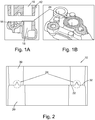
- Figures 1A and 1B show the seal deployed on a ladderframe, the seal may also be deployed in an oil pump body or oil cooler adaptor, for example.
- Figure 2 shows a cross section through a seal 10.
- the seal 10 is provided between a first part 20 and a second part 30.
- the first and second parts are provided with a first mating surface 22 and a second mating surface 32 respectively.
- the first mating surface 22 is provided with an annular projection 24.
- the projection 24 has a triangular cross section.
- the second mating surface 32 can be machined to provide a smooth surface to minimise leakage arising from the surface roughness of the part.
- the first mating surface 22 is provided on a sintered part. This allows the projection 24 to be formed integrally with the part 20 that is provided with the first mating surface 22.
- the seal 10 is formed when the two parts 20, 30 are brought together and pressure is applied perpendicular to the join between the parts, i.e. vertically as illustrated in Figure 2 .
- the projection 24 on the harder, sintered part 20 deforms the smooth surface of the second mating surface 32 forming an indentation into which the projection 24 fits.
- the seal 10 is therefore formed between the two mating surfaces.
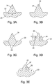
- Figures 3A to 3E show alternative cross sectional profiles that may be applied to the projection 24.
- the projections 24 shown in Figures 3A to 3E each have a base width W and height H.
- the base width W of the projection can vary between 1mm and 5mm, for example 3mm.
- the height H of the projection should exceed 1mm, for example 3mm, 4mm or even up to 5mm. Projections exceeding 10mm in height are impractical because the pressures required to deform the second mating surface sufficiently to form a seal are excessive and can compromise the integrity of the parts 20, 30.
- the ratio of the base width to the height is typically around 1, although it can be more than one or less than one. However, it would not generally exceed 10 or be less than 0.1 because such extreme shapes can be difficult to sinter.
- Figure 3A shows a projection 24 (not claimed) that has a cross section of an isosceles triangle.
- the height H is approximately equal to the width W and therefore the ratio of width to height is approximately equal to one.
- Figure 3B shows a projection 24 (not claimed) wherein the triangular cross section has been modified by providing a curved tip 26.
- This configuration is particularly appropriate if the part 30 including the second mating surface 32 is prone to failure by brittle fracture as the curved tip 26 decreases the initial pressure experienced by the second mating surface 32.
- Figure 3C shows a projection 24 provided with two grooves 28, one at either side of the projection.
- the grooves 28 provide a location into which displaced material from the second mating surface 32 can collect and thus providing a more tortuous path for fluid.
- the grooves 28 can be provided around the entire circumference of the annular projection or they may be provided discontinuously. Although two grooves 28 are shown in Figure 3C , a symmetrical configuration is not essential. A groove 28 could be provided at one side of the projection 24 only.
- Figure 3D shows a projection 24 (not claimed) including a curved tip 26 and two grooves 28 at a height h 1 above the first mating surface 22.
- the two grooves 28 have a depth h 2 , which is smaller than h 1 .
- the two grooves 28 are illustrated in Figure 3D as being at the same height h 1 above the first mating surface 22, in some embodiments the grooves 28 may be at different heights.
- Figure 3E shows a more complex shaped projection 24 (not claimed) including a lower portion 25 having height h 1 a first angle of inclination ⁇ , and an upper portion 27 having a second angle of inclination ⁇ .
- ⁇ is greater than ⁇ .
Landscapes
- Engineering & Computer Science (AREA)
- General Engineering & Computer Science (AREA)
- Mechanical Engineering (AREA)
- Chemical & Material Sciences (AREA)
- Combustion & Propulsion (AREA)
- Gasket Seals (AREA)
Applications Claiming Priority (1)
| Application Number | Priority Date | Filing Date | Title |
|---|---|---|---|
| GB1606733.2A GB2549486B (en) | 2016-04-18 | 2016-04-18 | Improvements in or relating to metal-to-metal sealing |
Publications (2)
| Publication Number | Publication Date |
|---|---|
| EP3236113A1 EP3236113A1 (en) | 2017-10-25 |
| EP3236113B1 true EP3236113B1 (en) | 2021-10-20 |
Family
ID=58489642
Family Applications (1)
| Application Number | Title | Priority Date | Filing Date |
|---|---|---|---|
| EP17165078.1A Active EP3236113B1 (en) | 2016-04-18 | 2017-04-05 | Improvements in or relating to metal-to-metal sealing |
Country Status (6)
| Country | Link |
|---|---|
| US (1) | US10393267B2 (zh) |
| EP (1) | EP3236113B1 (zh) |
| CN (1) | CN107304731B (zh) |
| GB (1) | GB2549486B (zh) |
| MX (1) | MX2017004954A (zh) |
| RU (1) | RU2727835C2 (zh) |
Families Citing this family (4)
| Publication number | Priority date | Publication date | Assignee | Title |
|---|---|---|---|---|
| US11598418B2 (en) * | 2020-04-14 | 2023-03-07 | Patriot Research Center, LLC | Metal to metal vee seal |
| CN113617142B (zh) | 2020-05-07 | 2023-04-18 | 钰祥企业股份有限公司 | 过滤模块 |
| JP2022128915A (ja) * | 2021-02-24 | 2022-09-05 | Ntn株式会社 | シール付軸受 |
| CN114321386A (zh) * | 2021-12-29 | 2022-04-12 | 重庆长安汽车股份有限公司 | 一种电动尾翼执行器密封结构及汽车 |
Citations (1)
| Publication number | Priority date | Publication date | Assignee | Title |
|---|---|---|---|---|
| JP2012082891A (ja) * | 2010-10-08 | 2012-04-26 | Musashino Eng:Kk | 真空容器におけるフランジ部のシール構造及びシール方法 |
Family Cites Families (20)
| Publication number | Priority date | Publication date | Assignee | Title |
|---|---|---|---|---|
| DE814977C (de) * | 1948-10-02 | 1951-09-27 | Bergbau Und Huettenbedarf Ag F | Dichtungsringe aus Sintereisen |
| DE921903C (de) * | 1952-10-23 | 1954-12-30 | Hans Kreidel Jun | Dichtring aus Stahl |
| US3403717A (en) * | 1966-02-14 | 1968-10-01 | Jerome H. Lemelson | Sealing and bonding device |
| US3937478A (en) * | 1974-11-18 | 1976-02-10 | Lloyd Mancebo | Coining seal |
| JPS5954857A (ja) * | 1982-09-21 | 1984-03-29 | Toshiba Corp | シ−ル機構 |
| GB2284872B (en) * | 1991-12-30 | 1996-08-28 | Japan Atomic Energy Res Inst | Vacuum flange |
| US6123339A (en) * | 1997-05-20 | 2000-09-26 | Daiso Corporation | Non-gasket sealing structure |
| JP4389186B2 (ja) * | 1998-02-23 | 2009-12-24 | 忠弘 大見 | ガスケットおよび管継手 |
| JP2001164304A (ja) * | 1999-12-07 | 2001-06-19 | Denso Corp | シール面を有する金属焼結体及びその製造方法 |
| AT507265B1 (de) | 2008-09-01 | 2010-07-15 | Miba Sinter Austria Gmbh | Lagerdeckel |
| US20100090410A1 (en) * | 2008-10-10 | 2010-04-15 | Baker Hughes Incorporated | Expandable metal-to-metal seal |
| KR101371452B1 (ko) * | 2008-11-26 | 2014-03-10 | 기아자동차주식회사 | 엔진의 레더프레임 |
| JP2010164304A (ja) * | 2010-04-27 | 2010-07-29 | Crave:Kk | ライター |
| CN102032401B (zh) * | 2010-12-29 | 2012-10-31 | 海盐管件制造有限公司 | 金属对金属尖角密封焊接式管接头 |
| JP5535997B2 (ja) * | 2011-08-05 | 2014-07-02 | 株式会社鷺宮製作所 | シール構造及び温度膨張弁 |
| CN104246245B (zh) | 2012-04-26 | 2017-06-06 | Gkn烧结金属有限公司 | 具有定位特征的主轴承盖 |
| TWI467037B (zh) * | 2012-05-14 | 2015-01-01 | Chunghwa Picture Tubes Ltd | 用於鍍膜製程之玻璃基板堆疊結構、裝置及方法 |
| JP6434417B2 (ja) | 2012-11-19 | 2018-12-05 | ジーケーエヌ シンター メタルズ、エル・エル・シー | 変形自在パッドを備えたコンポーネント |
| RU134279U1 (ru) * | 2013-06-17 | 2013-11-10 | Общество с ограниченной ответственностью "Скважинные термотехнологии" | Герметичное резьбовое соединение нефтепромысловых труб |
| DE202014102781U1 (de) | 2014-06-16 | 2014-07-08 | Ford Global Technologies, Llc | Gleitlager für eine Brennkraftmaschine |
-
2016
- 2016-04-18 GB GB1606733.2A patent/GB2549486B/en active Active
-
2017
- 2017-03-22 RU RU2017109587A patent/RU2727835C2/ru active
- 2017-04-05 EP EP17165078.1A patent/EP3236113B1/en active Active
- 2017-04-12 US US15/486,165 patent/US10393267B2/en not_active Expired - Fee Related
- 2017-04-17 MX MX2017004954A patent/MX2017004954A/es unknown
- 2017-04-18 CN CN201710250930.6A patent/CN107304731B/zh active Active
Patent Citations (1)
| Publication number | Priority date | Publication date | Assignee | Title |
|---|---|---|---|---|
| JP2012082891A (ja) * | 2010-10-08 | 2012-04-26 | Musashino Eng:Kk | 真空容器におけるフランジ部のシール構造及びシール方法 |
Also Published As
| Publication number | Publication date |
|---|---|
| GB2549486A (en) | 2017-10-25 |
| US20170299059A1 (en) | 2017-10-19 |
| EP3236113A1 (en) | 2017-10-25 |
| CN107304731B (zh) | 2021-11-05 |
| RU2017109587A3 (zh) | 2020-05-21 |
| CN107304731A (zh) | 2017-10-31 |
| GB2549486B (en) | 2020-12-02 |
| RU2017109587A (ru) | 2018-09-24 |
| RU2727835C2 (ru) | 2020-07-24 |
| MX2017004954A (es) | 2018-08-16 |
| US10393267B2 (en) | 2019-08-27 |
Similar Documents
| Publication | Publication Date | Title |
|---|---|---|
| EP3236113B1 (en) | Improvements in or relating to metal-to-metal sealing | |
| CN112166270B (zh) | 带密封件的阀和阀座 | |
| US10612660B2 (en) | Gasket | |
| JP4324607B2 (ja) | 非石綿ガスケット | |
| US6695357B2 (en) | Threaded pipe connection having a retainer gasket with pressure relief vents | |
| EP3239563B1 (en) | Metal gasket | |
| US20060001222A1 (en) | Gasket | |
| JP2006348995A (ja) | リップタイプシール | |
| US9841103B2 (en) | Metal gasket | |
| JP6955739B2 (ja) | 管継手 | |
| US3436085A (en) | Sealing structure embodying deformable ring | |
| JP2011094667A (ja) | ガスケット及び密封構造 | |
| US20180119819A1 (en) | Regulating valve | |
| CN205225474U (zh) | 一种内燃机气缸盖燃气密封结构 | |
| US6588762B2 (en) | Lathe cut face seal and method for sealing irregularly shaped cavity | |
| US20130134707A1 (en) | Pipe coupling for the fluid-tight attachment of components in an air conditioning system | |
| US20140319829A1 (en) | Component having a flange defining a groove therein | |
| EP3153747A1 (en) | Variable compression height integrated seal | |
| US10323753B2 (en) | Gasket seal seat ring | |
| EP3132161B1 (en) | Ez-seal assembly joining fluid pathways | |
| RU2638707C2 (ru) | Кольцевая металлическая статическая прокладка | |
| CN107461274B (zh) | 通过偏转进行的发动机油流控制 | |
| US20220057029A1 (en) | Metal seal comprising a textured outer sealing layer | |
| RU193610U1 (ru) | Поршень ускорительного насоса карбюратора | |
| CN216045416U (zh) | 用于容器的密封圈和一种容器 |
Legal Events
| Date | Code | Title | Description |
|---|---|---|---|
| PUAI | Public reference made under article 153(3) epc to a published international application that has entered the european phase |
Free format text: ORIGINAL CODE: 0009012 |
|
| STAA | Information on the status of an ep patent application or granted ep patent |
Free format text: STATUS: THE APPLICATION HAS BEEN PUBLISHED |
|
| AK | Designated contracting states |
Kind code of ref document: A1 Designated state(s): AL AT BE BG CH CY CZ DE DK EE ES FI FR GB GR HR HU IE IS IT LI LT LU LV MC MK MT NL NO PL PT RO RS SE SI SK SM TR |
|
| AX | Request for extension of the european patent |
Extension state: BA ME |
|
| STAA | Information on the status of an ep patent application or granted ep patent |
Free format text: STATUS: REQUEST FOR EXAMINATION WAS MADE |
|
| 17P | Request for examination filed |
Effective date: 20180425 |
|
| RBV | Designated contracting states (corrected) |
Designated state(s): AL AT BE BG CH CY CZ DE DK EE ES FI FR GB GR HR HU IE IS IT LI LT LU LV MC MK MT NL NO PL PT RO RS SE SI SK SM TR |
|
| STAA | Information on the status of an ep patent application or granted ep patent |
Free format text: STATUS: EXAMINATION IS IN PROGRESS |
|
| 17Q | First examination report despatched |
Effective date: 20190812 |
|
| STAA | Information on the status of an ep patent application or granted ep patent |
Free format text: STATUS: EXAMINATION IS IN PROGRESS |
|
| GRAP | Despatch of communication of intention to grant a patent |
Free format text: ORIGINAL CODE: EPIDOSNIGR1 |
|
| STAA | Information on the status of an ep patent application or granted ep patent |
Free format text: STATUS: GRANT OF PATENT IS INTENDED |
|
| INTG | Intention to grant announced |
Effective date: 20210510 |
|
| GRAS | Grant fee paid |
Free format text: ORIGINAL CODE: EPIDOSNIGR3 |
|
| GRAA | (expected) grant |
Free format text: ORIGINAL CODE: 0009210 |
|
| STAA | Information on the status of an ep patent application or granted ep patent |
Free format text: STATUS: THE PATENT HAS BEEN GRANTED |
|
| AK | Designated contracting states |
Kind code of ref document: B1 Designated state(s): AL AT BE BG CH CY CZ DE DK EE ES FI FR GB GR HR HU IE IS IT LI LT LU LV MC MK MT NL NO PL PT RO RS SE SI SK SM TR |
|
| REG | Reference to a national code |
Ref country code: GB Ref legal event code: FG4D |
|
| REG | Reference to a national code |
Ref country code: CH Ref legal event code: EP |
|
| REG | Reference to a national code |
Ref country code: IE Ref legal event code: FG4D |
|
| REG | Reference to a national code |
Ref country code: DE Ref legal event code: R096 Ref document number: 602017047779 Country of ref document: DE |
|
| REG | Reference to a national code |
Ref country code: AT Ref legal event code: REF Ref document number: 1440211 Country of ref document: AT Kind code of ref document: T Effective date: 20211115 |
|
| REG | Reference to a national code |
Ref country code: LT Ref legal event code: MG9D |
|
| REG | Reference to a national code |
Ref country code: NL Ref legal event code: MP Effective date: 20211020 |
|
| REG | Reference to a national code |
Ref country code: AT Ref legal event code: MK05 Ref document number: 1440211 Country of ref document: AT Kind code of ref document: T Effective date: 20211020 |
|
| PG25 | Lapsed in a contracting state [announced via postgrant information from national office to epo] |
Ref country code: RS Free format text: LAPSE BECAUSE OF FAILURE TO SUBMIT A TRANSLATION OF THE DESCRIPTION OR TO PAY THE FEE WITHIN THE PRESCRIBED TIME-LIMIT Effective date: 20211020 Ref country code: LT Free format text: LAPSE BECAUSE OF FAILURE TO SUBMIT A TRANSLATION OF THE DESCRIPTION OR TO PAY THE FEE WITHIN THE PRESCRIBED TIME-LIMIT Effective date: 20211020 Ref country code: FI Free format text: LAPSE BECAUSE OF FAILURE TO SUBMIT A TRANSLATION OF THE DESCRIPTION OR TO PAY THE FEE WITHIN THE PRESCRIBED TIME-LIMIT Effective date: 20211020 Ref country code: BG Free format text: LAPSE BECAUSE OF FAILURE TO SUBMIT A TRANSLATION OF THE DESCRIPTION OR TO PAY THE FEE WITHIN THE PRESCRIBED TIME-LIMIT Effective date: 20220120 Ref country code: AT Free format text: LAPSE BECAUSE OF FAILURE TO SUBMIT A TRANSLATION OF THE DESCRIPTION OR TO PAY THE FEE WITHIN THE PRESCRIBED TIME-LIMIT Effective date: 20211020 |
|
| PG25 | Lapsed in a contracting state [announced via postgrant information from national office to epo] |
Ref country code: IS Free format text: LAPSE BECAUSE OF FAILURE TO SUBMIT A TRANSLATION OF THE DESCRIPTION OR TO PAY THE FEE WITHIN THE PRESCRIBED TIME-LIMIT Effective date: 20220220 Ref country code: SE Free format text: LAPSE BECAUSE OF FAILURE TO SUBMIT A TRANSLATION OF THE DESCRIPTION OR TO PAY THE FEE WITHIN THE PRESCRIBED TIME-LIMIT Effective date: 20211020 Ref country code: PT Free format text: LAPSE BECAUSE OF FAILURE TO SUBMIT A TRANSLATION OF THE DESCRIPTION OR TO PAY THE FEE WITHIN THE PRESCRIBED TIME-LIMIT Effective date: 20220221 Ref country code: PL Free format text: LAPSE BECAUSE OF FAILURE TO SUBMIT A TRANSLATION OF THE DESCRIPTION OR TO PAY THE FEE WITHIN THE PRESCRIBED TIME-LIMIT Effective date: 20211020 Ref country code: NO Free format text: LAPSE BECAUSE OF FAILURE TO SUBMIT A TRANSLATION OF THE DESCRIPTION OR TO PAY THE FEE WITHIN THE PRESCRIBED TIME-LIMIT Effective date: 20220120 Ref country code: NL Free format text: LAPSE BECAUSE OF FAILURE TO SUBMIT A TRANSLATION OF THE DESCRIPTION OR TO PAY THE FEE WITHIN THE PRESCRIBED TIME-LIMIT Effective date: 20211020 Ref country code: LV Free format text: LAPSE BECAUSE OF FAILURE TO SUBMIT A TRANSLATION OF THE DESCRIPTION OR TO PAY THE FEE WITHIN THE PRESCRIBED TIME-LIMIT Effective date: 20211020 Ref country code: HR Free format text: LAPSE BECAUSE OF FAILURE TO SUBMIT A TRANSLATION OF THE DESCRIPTION OR TO PAY THE FEE WITHIN THE PRESCRIBED TIME-LIMIT Effective date: 20211020 Ref country code: GR Free format text: LAPSE BECAUSE OF FAILURE TO SUBMIT A TRANSLATION OF THE DESCRIPTION OR TO PAY THE FEE WITHIN THE PRESCRIBED TIME-LIMIT Effective date: 20220121 Ref country code: ES Free format text: LAPSE BECAUSE OF FAILURE TO SUBMIT A TRANSLATION OF THE DESCRIPTION OR TO PAY THE FEE WITHIN THE PRESCRIBED TIME-LIMIT Effective date: 20211020 |
|
| REG | Reference to a national code |
Ref country code: DE Ref legal event code: R097 Ref document number: 602017047779 Country of ref document: DE |
|
| PG25 | Lapsed in a contracting state [announced via postgrant information from national office to epo] |
Ref country code: SM Free format text: LAPSE BECAUSE OF FAILURE TO SUBMIT A TRANSLATION OF THE DESCRIPTION OR TO PAY THE FEE WITHIN THE PRESCRIBED TIME-LIMIT Effective date: 20211020 Ref country code: SK Free format text: LAPSE BECAUSE OF FAILURE TO SUBMIT A TRANSLATION OF THE DESCRIPTION OR TO PAY THE FEE WITHIN THE PRESCRIBED TIME-LIMIT Effective date: 20211020 Ref country code: RO Free format text: LAPSE BECAUSE OF FAILURE TO SUBMIT A TRANSLATION OF THE DESCRIPTION OR TO PAY THE FEE WITHIN THE PRESCRIBED TIME-LIMIT Effective date: 20211020 Ref country code: EE Free format text: LAPSE BECAUSE OF FAILURE TO SUBMIT A TRANSLATION OF THE DESCRIPTION OR TO PAY THE FEE WITHIN THE PRESCRIBED TIME-LIMIT Effective date: 20211020 Ref country code: DK Free format text: LAPSE BECAUSE OF FAILURE TO SUBMIT A TRANSLATION OF THE DESCRIPTION OR TO PAY THE FEE WITHIN THE PRESCRIBED TIME-LIMIT Effective date: 20211020 Ref country code: CZ Free format text: LAPSE BECAUSE OF FAILURE TO SUBMIT A TRANSLATION OF THE DESCRIPTION OR TO PAY THE FEE WITHIN THE PRESCRIBED TIME-LIMIT Effective date: 20211020 |
|
| PLBE | No opposition filed within time limit |
Free format text: ORIGINAL CODE: 0009261 |
|
| STAA | Information on the status of an ep patent application or granted ep patent |
Free format text: STATUS: NO OPPOSITION FILED WITHIN TIME LIMIT |
|
| 26N | No opposition filed |
Effective date: 20220721 |
|
| PG25 | Lapsed in a contracting state [announced via postgrant information from national office to epo] |
Ref country code: AL Free format text: LAPSE BECAUSE OF FAILURE TO SUBMIT A TRANSLATION OF THE DESCRIPTION OR TO PAY THE FEE WITHIN THE PRESCRIBED TIME-LIMIT Effective date: 20211020 |
|
| PG25 | Lapsed in a contracting state [announced via postgrant information from national office to epo] |
Ref country code: SI Free format text: LAPSE BECAUSE OF FAILURE TO SUBMIT A TRANSLATION OF THE DESCRIPTION OR TO PAY THE FEE WITHIN THE PRESCRIBED TIME-LIMIT Effective date: 20211020 |
|
| REG | Reference to a national code |
Ref country code: CH Ref legal event code: PL |
|
| GBPC | Gb: european patent ceased through non-payment of renewal fee |
Effective date: 20220405 |
|
| REG | Reference to a national code |
Ref country code: BE Ref legal event code: MM Effective date: 20220430 |
|
| PG25 | Lapsed in a contracting state [announced via postgrant information from national office to epo] |
Ref country code: MC Free format text: LAPSE BECAUSE OF FAILURE TO SUBMIT A TRANSLATION OF THE DESCRIPTION OR TO PAY THE FEE WITHIN THE PRESCRIBED TIME-LIMIT Effective date: 20211020 Ref country code: LU Free format text: LAPSE BECAUSE OF NON-PAYMENT OF DUE FEES Effective date: 20220405 Ref country code: LI Free format text: LAPSE BECAUSE OF NON-PAYMENT OF DUE FEES Effective date: 20220430 Ref country code: GB Free format text: LAPSE BECAUSE OF NON-PAYMENT OF DUE FEES Effective date: 20220405 Ref country code: FR Free format text: LAPSE BECAUSE OF NON-PAYMENT OF DUE FEES Effective date: 20220430 Ref country code: CH Free format text: LAPSE BECAUSE OF NON-PAYMENT OF DUE FEES Effective date: 20220430 |
|
| PG25 | Lapsed in a contracting state [announced via postgrant information from national office to epo] |
Ref country code: BE Free format text: LAPSE BECAUSE OF NON-PAYMENT OF DUE FEES Effective date: 20220430 |
|
| PG25 | Lapsed in a contracting state [announced via postgrant information from national office to epo] |
Ref country code: IE Free format text: LAPSE BECAUSE OF NON-PAYMENT OF DUE FEES Effective date: 20220405 |
|
| PG25 | Lapsed in a contracting state [announced via postgrant information from national office to epo] |
Ref country code: IT Free format text: LAPSE BECAUSE OF FAILURE TO SUBMIT A TRANSLATION OF THE DESCRIPTION OR TO PAY THE FEE WITHIN THE PRESCRIBED TIME-LIMIT Effective date: 20211020 |
|
| P01 | Opt-out of the competence of the unified patent court (upc) registered |
Effective date: 20230620 |
|
| PG25 | Lapsed in a contracting state [announced via postgrant information from national office to epo] |
Ref country code: HU Free format text: LAPSE BECAUSE OF FAILURE TO SUBMIT A TRANSLATION OF THE DESCRIPTION OR TO PAY THE FEE WITHIN THE PRESCRIBED TIME-LIMIT; INVALID AB INITIO Effective date: 20170405 |
|
| PG25 | Lapsed in a contracting state [announced via postgrant information from national office to epo] |
Ref country code: MK Free format text: LAPSE BECAUSE OF FAILURE TO SUBMIT A TRANSLATION OF THE DESCRIPTION OR TO PAY THE FEE WITHIN THE PRESCRIBED TIME-LIMIT Effective date: 20211020 Ref country code: CY Free format text: LAPSE BECAUSE OF FAILURE TO SUBMIT A TRANSLATION OF THE DESCRIPTION OR TO PAY THE FEE WITHIN THE PRESCRIBED TIME-LIMIT Effective date: 20211020 |
|
| PGFP | Annual fee paid to national office [announced via postgrant information from national office to epo] |
Ref country code: DE Payment date: 20240315 Year of fee payment: 8 |