EP3235050B1 - Verfahren zur verwaltung eines hybridantriebstrangs eines kraftfahrzeugs - Google Patents
Verfahren zur verwaltung eines hybridantriebstrangs eines kraftfahrzeugs Download PDFInfo
- Publication number
- EP3235050B1 EP3235050B1 EP15817989.5A EP15817989A EP3235050B1 EP 3235050 B1 EP3235050 B1 EP 3235050B1 EP 15817989 A EP15817989 A EP 15817989A EP 3235050 B1 EP3235050 B1 EP 3235050B1
- Authority
- EP
- European Patent Office
- Prior art keywords
- temperature
- power battery
- heating system
- battery
- heat engine
- Prior art date
- Legal status (The legal status is an assumption and is not a legal conclusion. Google has not performed a legal analysis and makes no representation as to the accuracy of the status listed.)
- Active
Links
Images



Classifications
-
- B—PERFORMING OPERATIONS; TRANSPORTING
- B60—VEHICLES IN GENERAL
- B60L—PROPULSION OF ELECTRICALLY-PROPELLED VEHICLES; SUPPLYING ELECTRIC POWER FOR AUXILIARY EQUIPMENT OF ELECTRICALLY-PROPELLED VEHICLES; ELECTRODYNAMIC BRAKE SYSTEMS FOR VEHICLES IN GENERAL; MAGNETIC SUSPENSION OR LEVITATION FOR VEHICLES; MONITORING OPERATING VARIABLES OF ELECTRICALLY-PROPELLED VEHICLES; ELECTRIC SAFETY DEVICES FOR ELECTRICALLY-PROPELLED VEHICLES
- B60L58/00—Methods or circuit arrangements for monitoring or controlling batteries or fuel cells, specially adapted for electric vehicles
- B60L58/10—Methods or circuit arrangements for monitoring or controlling batteries or fuel cells, specially adapted for electric vehicles for monitoring or controlling batteries
- B60L58/12—Methods or circuit arrangements for monitoring or controlling batteries or fuel cells, specially adapted for electric vehicles for monitoring or controlling batteries responding to state of charge [SoC]
-
- B—PERFORMING OPERATIONS; TRANSPORTING
- B60—VEHICLES IN GENERAL
- B60L—PROPULSION OF ELECTRICALLY-PROPELLED VEHICLES; SUPPLYING ELECTRIC POWER FOR AUXILIARY EQUIPMENT OF ELECTRICALLY-PROPELLED VEHICLES; ELECTRODYNAMIC BRAKE SYSTEMS FOR VEHICLES IN GENERAL; MAGNETIC SUSPENSION OR LEVITATION FOR VEHICLES; MONITORING OPERATING VARIABLES OF ELECTRICALLY-PROPELLED VEHICLES; ELECTRIC SAFETY DEVICES FOR ELECTRICALLY-PROPELLED VEHICLES
- B60L50/00—Electric propulsion with power supplied within the vehicle
- B60L50/10—Electric propulsion with power supplied within the vehicle using propulsion power supplied by engine-driven generators, e.g. generators driven by combustion engines
- B60L50/16—Electric propulsion with power supplied within the vehicle using propulsion power supplied by engine-driven generators, e.g. generators driven by combustion engines with provision for separate direct mechanical propulsion
-
- B—PERFORMING OPERATIONS; TRANSPORTING
- B60—VEHICLES IN GENERAL
- B60L—PROPULSION OF ELECTRICALLY-PROPELLED VEHICLES; SUPPLYING ELECTRIC POWER FOR AUXILIARY EQUIPMENT OF ELECTRICALLY-PROPELLED VEHICLES; ELECTRODYNAMIC BRAKE SYSTEMS FOR VEHICLES IN GENERAL; MAGNETIC SUSPENSION OR LEVITATION FOR VEHICLES; MONITORING OPERATING VARIABLES OF ELECTRICALLY-PROPELLED VEHICLES; ELECTRIC SAFETY DEVICES FOR ELECTRICALLY-PROPELLED VEHICLES
- B60L58/00—Methods or circuit arrangements for monitoring or controlling batteries or fuel cells, specially adapted for electric vehicles
- B60L58/10—Methods or circuit arrangements for monitoring or controlling batteries or fuel cells, specially adapted for electric vehicles for monitoring or controlling batteries
- B60L58/24—Methods or circuit arrangements for monitoring or controlling batteries or fuel cells, specially adapted for electric vehicles for monitoring or controlling batteries for controlling the temperature of batteries
- B60L58/25—Methods or circuit arrangements for monitoring or controlling batteries or fuel cells, specially adapted for electric vehicles for monitoring or controlling batteries for controlling the temperature of batteries by controlling the electric load
-
- B—PERFORMING OPERATIONS; TRANSPORTING
- B60—VEHICLES IN GENERAL
- B60L—PROPULSION OF ELECTRICALLY-PROPELLED VEHICLES; SUPPLYING ELECTRIC POWER FOR AUXILIARY EQUIPMENT OF ELECTRICALLY-PROPELLED VEHICLES; ELECTRODYNAMIC BRAKE SYSTEMS FOR VEHICLES IN GENERAL; MAGNETIC SUSPENSION OR LEVITATION FOR VEHICLES; MONITORING OPERATING VARIABLES OF ELECTRICALLY-PROPELLED VEHICLES; ELECTRIC SAFETY DEVICES FOR ELECTRICALLY-PROPELLED VEHICLES
- B60L58/00—Methods or circuit arrangements for monitoring or controlling batteries or fuel cells, specially adapted for electric vehicles
- B60L58/10—Methods or circuit arrangements for monitoring or controlling batteries or fuel cells, specially adapted for electric vehicles for monitoring or controlling batteries
- B60L58/24—Methods or circuit arrangements for monitoring or controlling batteries or fuel cells, specially adapted for electric vehicles for monitoring or controlling batteries for controlling the temperature of batteries
- B60L58/27—Methods or circuit arrangements for monitoring or controlling batteries or fuel cells, specially adapted for electric vehicles for monitoring or controlling batteries for controlling the temperature of batteries by heating
-
- B—PERFORMING OPERATIONS; TRANSPORTING
- B60—VEHICLES IN GENERAL
- B60W—CONJOINT CONTROL OF VEHICLE SUB-UNITS OF DIFFERENT TYPE OR DIFFERENT FUNCTION; CONTROL SYSTEMS SPECIALLY ADAPTED FOR HYBRID VEHICLES; ROAD VEHICLE DRIVE CONTROL SYSTEMS FOR PURPOSES NOT RELATED TO THE CONTROL OF A PARTICULAR SUB-UNIT
- B60W20/00—Control systems specially adapted for hybrid vehicles
- B60W20/10—Controlling the power contribution of each of the prime movers to meet required power demand
- B60W20/13—Controlling the power contribution of each of the prime movers to meet required power demand in order to stay within battery power input or output limits; in order to prevent overcharging or battery depletion
-
- H—ELECTRICITY
- H01—ELECTRIC ELEMENTS
- H01M—PROCESSES OR MEANS, e.g. BATTERIES, FOR THE DIRECT CONVERSION OF CHEMICAL ENERGY INTO ELECTRICAL ENERGY
- H01M10/00—Secondary cells; Manufacture thereof
- H01M10/60—Heating or cooling; Temperature control
- H01M10/61—Types of temperature control
-
- H—ELECTRICITY
- H01—ELECTRIC ELEMENTS
- H01M—PROCESSES OR MEANS, e.g. BATTERIES, FOR THE DIRECT CONVERSION OF CHEMICAL ENERGY INTO ELECTRICAL ENERGY
- H01M10/00—Secondary cells; Manufacture thereof
- H01M10/60—Heating or cooling; Temperature control
- H01M10/61—Types of temperature control
- H01M10/615—Heating or keeping warm
-
- H—ELECTRICITY
- H01—ELECTRIC ELEMENTS
- H01M—PROCESSES OR MEANS, e.g. BATTERIES, FOR THE DIRECT CONVERSION OF CHEMICAL ENERGY INTO ELECTRICAL ENERGY
- H01M10/00—Secondary cells; Manufacture thereof
- H01M10/60—Heating or cooling; Temperature control
- H01M10/62—Heating or cooling; Temperature control specially adapted for specific applications
- H01M10/625—Vehicles
-
- H—ELECTRICITY
- H01—ELECTRIC ELEMENTS
- H01M—PROCESSES OR MEANS, e.g. BATTERIES, FOR THE DIRECT CONVERSION OF CHEMICAL ENERGY INTO ELECTRICAL ENERGY
- H01M10/00—Secondary cells; Manufacture thereof
- H01M10/60—Heating or cooling; Temperature control
- H01M10/63—Control systems
-
- H—ELECTRICITY
- H01—ELECTRIC ELEMENTS
- H01M—PROCESSES OR MEANS, e.g. BATTERIES, FOR THE DIRECT CONVERSION OF CHEMICAL ENERGY INTO ELECTRICAL ENERGY
- H01M10/00—Secondary cells; Manufacture thereof
- H01M10/60—Heating or cooling; Temperature control
- H01M10/65—Means for temperature control structurally associated with the cells
- H01M10/651—Means for temperature control structurally associated with the cells characterised by parameters specified by a numeric value or mathematical formula, e.g. ratios, sizes or concentrations
-
- H—ELECTRICITY
- H01—ELECTRIC ELEMENTS
- H01M—PROCESSES OR MEANS, e.g. BATTERIES, FOR THE DIRECT CONVERSION OF CHEMICAL ENERGY INTO ELECTRICAL ENERGY
- H01M10/00—Secondary cells; Manufacture thereof
- H01M10/60—Heating or cooling; Temperature control
- H01M10/65—Means for temperature control structurally associated with the cells
- H01M10/657—Means for temperature control structurally associated with the cells by electric or electromagnetic means
- H01M10/6571—Resistive heaters
-
- H—ELECTRICITY
- H01—ELECTRIC ELEMENTS
- H01M—PROCESSES OR MEANS, e.g. BATTERIES, FOR THE DIRECT CONVERSION OF CHEMICAL ENERGY INTO ELECTRICAL ENERGY
- H01M10/00—Secondary cells; Manufacture thereof
- H01M10/60—Heating or cooling; Temperature control
- H01M10/66—Heat-exchange relationships between the cells and other systems, e.g. central heating systems or fuel cells
- H01M10/663—Heat-exchange relationships between the cells and other systems, e.g. central heating systems or fuel cells the system being an air-conditioner or an engine
-
- B—PERFORMING OPERATIONS; TRANSPORTING
- B60—VEHICLES IN GENERAL
- B60L—PROPULSION OF ELECTRICALLY-PROPELLED VEHICLES; SUPPLYING ELECTRIC POWER FOR AUXILIARY EQUIPMENT OF ELECTRICALLY-PROPELLED VEHICLES; ELECTRODYNAMIC BRAKE SYSTEMS FOR VEHICLES IN GENERAL; MAGNETIC SUSPENSION OR LEVITATION FOR VEHICLES; MONITORING OPERATING VARIABLES OF ELECTRICALLY-PROPELLED VEHICLES; ELECTRIC SAFETY DEVICES FOR ELECTRICALLY-PROPELLED VEHICLES
- B60L2240/00—Control parameters of input or output; Target parameters
- B60L2240/40—Drive Train control parameters
- B60L2240/44—Drive Train control parameters related to combustion engines
- B60L2240/445—Temperature
-
- B—PERFORMING OPERATIONS; TRANSPORTING
- B60—VEHICLES IN GENERAL
- B60L—PROPULSION OF ELECTRICALLY-PROPELLED VEHICLES; SUPPLYING ELECTRIC POWER FOR AUXILIARY EQUIPMENT OF ELECTRICALLY-PROPELLED VEHICLES; ELECTRODYNAMIC BRAKE SYSTEMS FOR VEHICLES IN GENERAL; MAGNETIC SUSPENSION OR LEVITATION FOR VEHICLES; MONITORING OPERATING VARIABLES OF ELECTRICALLY-PROPELLED VEHICLES; ELECTRIC SAFETY DEVICES FOR ELECTRICALLY-PROPELLED VEHICLES
- B60L2240/00—Control parameters of input or output; Target parameters
- B60L2240/40—Drive Train control parameters
- B60L2240/54—Drive Train control parameters related to batteries
- B60L2240/545—Temperature
-
- B—PERFORMING OPERATIONS; TRANSPORTING
- B60—VEHICLES IN GENERAL
- B60L—PROPULSION OF ELECTRICALLY-PROPELLED VEHICLES; SUPPLYING ELECTRIC POWER FOR AUXILIARY EQUIPMENT OF ELECTRICALLY-PROPELLED VEHICLES; ELECTRODYNAMIC BRAKE SYSTEMS FOR VEHICLES IN GENERAL; MAGNETIC SUSPENSION OR LEVITATION FOR VEHICLES; MONITORING OPERATING VARIABLES OF ELECTRICALLY-PROPELLED VEHICLES; ELECTRIC SAFETY DEVICES FOR ELECTRICALLY-PROPELLED VEHICLES
- B60L2240/00—Control parameters of input or output; Target parameters
- B60L2240/80—Time limits
-
- B—PERFORMING OPERATIONS; TRANSPORTING
- B60—VEHICLES IN GENERAL
- B60Y—INDEXING SCHEME RELATING TO ASPECTS CROSS-CUTTING VEHICLE TECHNOLOGY
- B60Y2200/00—Type of vehicle
- B60Y2200/90—Vehicles comprising electric prime movers
- B60Y2200/92—Hybrid vehicles
-
- H—ELECTRICITY
- H01—ELECTRIC ELEMENTS
- H01M—PROCESSES OR MEANS, e.g. BATTERIES, FOR THE DIRECT CONVERSION OF CHEMICAL ENERGY INTO ELECTRICAL ENERGY
- H01M2220/00—Batteries for particular applications
- H01M2220/20—Batteries in motive systems, e.g. vehicle, ship, plane
-
- Y—GENERAL TAGGING OF NEW TECHNOLOGICAL DEVELOPMENTS; GENERAL TAGGING OF CROSS-SECTIONAL TECHNOLOGIES SPANNING OVER SEVERAL SECTIONS OF THE IPC; TECHNICAL SUBJECTS COVERED BY FORMER USPC CROSS-REFERENCE ART COLLECTIONS [XRACs] AND DIGESTS
- Y02—TECHNOLOGIES OR APPLICATIONS FOR MITIGATION OR ADAPTATION AGAINST CLIMATE CHANGE
- Y02E—REDUCTION OF GREENHOUSE GAS [GHG] EMISSIONS, RELATED TO ENERGY GENERATION, TRANSMISSION OR DISTRIBUTION
- Y02E60/00—Enabling technologies; Technologies with a potential or indirect contribution to GHG emissions mitigation
- Y02E60/10—Energy storage using batteries
-
- Y—GENERAL TAGGING OF NEW TECHNOLOGICAL DEVELOPMENTS; GENERAL TAGGING OF CROSS-SECTIONAL TECHNOLOGIES SPANNING OVER SEVERAL SECTIONS OF THE IPC; TECHNICAL SUBJECTS COVERED BY FORMER USPC CROSS-REFERENCE ART COLLECTIONS [XRACs] AND DIGESTS
- Y02—TECHNOLOGIES OR APPLICATIONS FOR MITIGATION OR ADAPTATION AGAINST CLIMATE CHANGE
- Y02T—CLIMATE CHANGE MITIGATION TECHNOLOGIES RELATED TO TRANSPORTATION
- Y02T10/00—Road transport of goods or passengers
- Y02T10/60—Other road transportation technologies with climate change mitigation effect
- Y02T10/70—Energy storage systems for electromobility, e.g. batteries
-
- Y—GENERAL TAGGING OF NEW TECHNOLOGICAL DEVELOPMENTS; GENERAL TAGGING OF CROSS-SECTIONAL TECHNOLOGIES SPANNING OVER SEVERAL SECTIONS OF THE IPC; TECHNICAL SUBJECTS COVERED BY FORMER USPC CROSS-REFERENCE ART COLLECTIONS [XRACs] AND DIGESTS
- Y02—TECHNOLOGIES OR APPLICATIONS FOR MITIGATION OR ADAPTATION AGAINST CLIMATE CHANGE
- Y02T—CLIMATE CHANGE MITIGATION TECHNOLOGIES RELATED TO TRANSPORTATION
- Y02T10/00—Road transport of goods or passengers
- Y02T10/60—Other road transportation technologies with climate change mitigation effect
- Y02T10/7072—Electromobility specific charging systems or methods for batteries, ultracapacitors, supercapacitors or double-layer capacitors
Definitions
- the invention relates to the field of motor vehicles of the hybrid type, that is to say to thermal and electrical motorization.
- the subject of the invention is more particularly a method for managing a power unit of a motor vehicle comprising a heat engine and an electric motor electrically connected to a battery pack.
- the document EP1065354 describes a heat exchanger recovering heat lost by the heat engine to transfer it to the battery. As a result, the rise in temperature of the battery is totally and passively slaved to the temperature rise of the heat engine, without any control.
- GB2509308 discloses a method for managing a power train of a motor vehicle comprising a heat engine and a battery pack.
- the object of the present invention is to propose a solution that overcomes the disadvantages listed above.
- the method comprises a step of controlling a heating system of the supply battery as a function of at least one measurement of a temperature representative of the operation of the heat engine.
- the driving step is such that it synchronizes the rise in temperature of the battery. supply to the temperature rise of the engine so that the first and second optimum operating temperatures are reached at the same time.
- the method comprises, for each step of measuring the temperature representative of the operation of the heat engine, a step of generating a set temperature, and the step of controlling the heating system comprises a step of activating the heating system to raise the actual temperature of the battery pack to the set temperature developed, especially if the actual temperature of the battery is lower than the set temperature.
- control step includes a step of measuring the current temperature of the supply battery and a step of determining a heating power of the heating system to be applied as a function of the set set temperature and the current measured temperature of the battery pack.
- each measurement of the temperature representative of the operation of the heat engine includes measuring the temperature of the coolant of the engine.
- the step of controlling the heating system of the supply battery comprises a step of collecting calories from a member of the heat-producing automobile vehicle due to the operation of the heat engine and a step of restitution of the less a portion of the calories taken from the battery pack.
- the calorie withdrawal step and the step of restoring said at least a portion of the calories use a thermal coupling element connecting said heat producing member to the battery pack.
- the step of controlling the heating system of the battery pack may include a step of charging or discharging the battery pack to cause joule effect its warming.
- the step of controlling the heating system of the battery pack may include an activation of resistive means internal to the battery pack.
- the invention also relates to a motor vehicle comprising a power unit comprising a heat engine and an electric motor electrically connected to a battery pack, said vehicle comprising a heating system of the battery pack, and a control module heating system configured to drive said heating system according to at least one measurement of a temperature representative of the operation of the engine.
- control module may include the elements necessary for the implementation of the method as described.
- the process described hereinafter differs in particular from the prior art in that it will be sought to determine a temperature representative of the operation of the heat engine (also called temperature representative of the temperature of the heat engine) and that this determined temperature, in particular by measurement, will influence the strategy of heating the battery of the electric motor.
- a temperature representative of the operation of the heat engine also called temperature representative of the temperature of the heat engine
- the heat engine participates in the propulsion of the motor vehicle from the operation of a fuel such as diesel or gasoline.
- the electric motor participates in the propulsion of the motor vehicle from the operation of a battery for powering the electric motor.
- the method which will be described below is particularly applicable to a hybrid motor vehicle in a post-startup phase in which the engine and the electric motor have not yet reached optimal operating temperatures.
- propulsion of the motor vehicle means a definition in the broad sense, that is to say the supply of energy to a motor vehicle to enable it to move. In this sense, the propulsion covers a vehicle by rear-wheel drive and / or by front-wheel drive.
- the invention is particularly related to a method of managing a power unit 1 of a motor vehicle comprising a heat engine 2 and an electric motor 3 electrically connected to a battery pack 4.
- the battery of 4 power supply allows the operation of the electric motor 3 so that it brings a torque to the wheels of the motor vehicle.
- the management method comprises a step of controlling a heating system 5 of the battery pack 4 according to at least one measuring a temperature representative of the operation of the heat engine 2.
- the heat engine 2 is associated with a first optimum operating temperature and the supply battery 4 is associated with a second optimum operating temperature.
- the control step is such that it synchronizes the rise in temperature of the battery pack 4 to the temperature rise of the heat engine 2 so that the first and second optimal operating temperatures are reached at the same time .
- the first and second optimum operating temperatures are different preferential.
- the first optimum operating temperature is lower than the second optimum operating temperature.
- the temperature rise of the heat engine 3 is automatic because of its operation.
- the management method makes it possible to control the rise in temperature of the supply battery 4 as a function of that of the heat engine 2.
- the driving mode of the driver selected for example between a flexible driving and a sporty driving is taken into account here.
- the temperature rise of the engine 2 is generally slow (a few minutes) or very slow if the driver is driving very slowly. It is therefore unnecessary to heat the battery pack 4 too quickly if the temperature rise of the heat engine 2 is slow.
- the temperature rise of the engine 2 is faster (that is to say that the driver has a "sporty" mode of driving), it is necessary to accelerate the temperature rise of the battery pack 4 .
- each measurement of the temperature representative of the operation of the heat engine 2 includes measuring the temperature of the coolant of the heat engine 2.
- the temperature of the coolant which is measured at the output of the engine 2 has the advantage of being a good indicator of the temperature of the heat engine 2 itself.
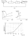
- the management method includes, for each step of measuring the temperature representative of the operation of the heat engine 2, a step of generating a set temperature. For example, for a measured temperature, it suffices to query a table or a function giving the set temperature T set point in function of the temperature T measured water Representative of the engine 2. The figure 3 illustrates such a function.
- the control step of the heating system 5 comprises a step of activating the heating system 5 to make the actual temperature of the battery pack 4 to the set target temperature. Especially, the actual temperature of the supply battery 4 is brought to the target temperature if the actual temperature of the battery is lower than the set temperature. It is then understood that the management method is particularly applicable to a motor vehicle after starting during the heating period.
- the driving step may comprise a step of measuring the current temperature of the supply battery and a step of determining a heating power of the heating system. to be applied according to the elaborated set temperature and the measured current temperature of the battery pack 4. More particularly, by knowing the measured current temperature of the battery pack 4 and the set temperature, it is possible to calculate a desired temperature variation. From the desired temperature variation, and knowing a control constant giving a power relative to degrees Celsius or Kelvin, it is possible to deduce the desired heating power.
- figure 4 schematically illustrates the logic of the management method which takes as input a representative temperature of the operation of the heat engine 2, T water in the illustrated example, and a measured temperature of the battery pack 4, T MesureBatterie in the example illustrated.
- the application of the function f makes it possible to obtain a set temperature T Setpoint .
- the full power of the battery pack 4 is necessary for a hybrid vehicle only when the engine 2 is considered hot.
- the engine 2 is considered hot when the temperature of the cooling water at the output of the engine 2 is 15 ° C.
- the goal is to synchronize the performance of the engine and the electric motor.
- it is proposed to synchronize the full power temperature of the battery pack 4 to the "target" temperature (previously evoked at 15 ° C) of the heat engine 2.
- a threshold example: 15 ° C
- the temperature of the cooling water and the temperature of the battery pack 4 are identical and equal to -20 ° C.
- the heat engine 2 is considered hot as soon as its water temperature becomes greater than 15 ° C and the battery pack 4 is capable of delivering all its power as soon as its temperature exceeds 25 ° C. Since the driver, by his way of driving, governs the rise in temperature of the engine 2, the temperature rise of the battery pack 4 is controlled so that it reaches 25 ° C when the engine 2 will reach 15 ° vs. It should be noted that this is not possible with the passive servo solution of the prior art mentioned above.
- FIGs 5 and 6 illustrate the evolution of the temperatures of the cooling water T water and the battery 4 T battery according to the implementation of the management method for a flexible driving ( figure 5 ) in which the optimum temperatures are reached after 20 minutes, and for a sporty driving ( figure 6 ) in which the optimum temperatures are reached after 7 minutes.
- a flexible driving figure 5
- a sporty driving figure 6
- the optimum temperatures are reached after 7 minutes.
- this has been chosen to apply a linear evolution between the temperature rise of the battery pack 4 and the rise in temperature of the heat engine 2.
- the graph of the figure 3 shows this linear evolution.
- T drums _ EVERYCTP - T drums _ sansCTP ⁇ P CTP hS ext . 1 - exp - t / ⁇ ⁇ represents the desired temperature variation evoked above, that is to say the difference between the measured temperature of the supply battery and the estimated set temperature.
- the figure 7 illustrates the influence of the operation of the motor vehicle on the water temperature of the engine 2 for a period of 30 minutes after starting the vehicle parked at -20 ° C (it follows that the engine water is - 20 ° C at start-up).
- the figure 8 illustrates for the curve of the figure 7 the evolution of the desired set temperature.
- the figure 9 shows the evolution of the actual temperature of the supply battery 4 according to the set temperature in the context where the management method is applied, while the figure 10 shows the evolution of the actual temperature of the battery pack when the management method is not applied. It is clear that without supply of temperature, the battery pack 4 can not provide all its power even after a rolling phase of 30 minutes.
- the figure 11 illustrates over time the supply of W heating system 5 to make the actual temperature of the battery supply 4 to that setpoint.
- the step of controlling the heating system 5 of the feed battery 4 comprises a step of taking heat from a member of the heat-producing motor vehicle as a result of the operation of the heat engine and a step of restoring heat. at least a portion of the calories taken from the battery pack 4. It is obvious that this calorie removal step is carried out when the set temperature developed is greater than the measured temperature of the battery pack 4, in other words, when a need is detected for heating the battery pack 4.
- the step of collecting calories and the step of restoring said at least part of the calories use a thermal coupling element connecting said heat producing member to the battery pack 4.
- each time a set temperature is developed it is measured a temperature of the battery pack 4 to have a vision adapted to the same time instant.
- the body of the motor vehicle producing heat due to the operation of the heat engine may, for example, be selected from a heat exchanger, an exhaust line of the motor vehicle, a water circuit including in the context of a engine THP (acronym for "Turbo High Pressure" in English), etc.
- the temperature rise of the battery pack 4 can be achieved by stimulating said battery pack 4 (cycles to increase its internal resistance).
- the step of controlling the heating system of the battery pack 4 may comprise a step of charging or discharging the battery pack 4 to cause Joule effect its warming.
- This use charge or discharge of the battery pack
- the step of controlling the heating system 5 of the battery pack 4 comprises an activation of resistive means internal to the battery pack 4.
- the method described above allows, by linking the rise in temperature of the engine to that of the battery by measurement (s) of temperature (s) representative (s) of that (s) of the engine, to better control the supply of calories to the battery depending on the use of the vehicle.
- the rise in temperature of the battery may be limited because not useful to driving. In this sense, it is possible to reduce the consumption of the vehicle and thus to promote the autonomy of the battery supplying the electric motor.
- the invention is of course also related to a motor vehicle comprising a power unit comprising a heat engine 2 and an electric motor electrically connected to a battery pack 4, said vehicle comprising a heating system 5 of the battery pack 4
- the vehicle comprises a control module 7 of the heating system configured so as to drive said heating system as a function of at least one measurement of a temperature representative of the operation of the heat engine.
- control module includes the elements necessary for the implementation of the management method as described.
- control module may comprise a computer program comprising the code means necessary for the progress of the steps of the management program.
- control module may comprise inputs connected to sensors, in particular a battery temperature sensor, a temperature sensor representative of the temperature of the heat engine and at least one output capable of transmitting to the heating system. instructions for the implementation or not of the heating of the battery pack.
Landscapes
- Engineering & Computer Science (AREA)
- Chemical & Material Sciences (AREA)
- General Chemical & Material Sciences (AREA)
- Electrochemistry (AREA)
- Chemical Kinetics & Catalysis (AREA)
- Manufacturing & Machinery (AREA)
- Mechanical Engineering (AREA)
- Transportation (AREA)
- Power Engineering (AREA)
- Physics & Mathematics (AREA)
- Sustainable Energy (AREA)
- Life Sciences & Earth Sciences (AREA)
- Sustainable Development (AREA)
- Automation & Control Theory (AREA)
- Algebra (AREA)
- Electromagnetism (AREA)
- Mathematical Analysis (AREA)
- General Physics & Mathematics (AREA)
- Pure & Applied Mathematics (AREA)
- Mathematical Optimization (AREA)
- Electric Propulsion And Braking For Vehicles (AREA)
- Hybrid Electric Vehicles (AREA)
- Secondary Cells (AREA)
- Control Of Driving Devices And Active Controlling Of Vehicle (AREA)
Claims (9)
- Verfahren zur Steuerung der Antriebsgruppe (1) eines Kraftfahrzeugs umfassend einen Verbrennungsmotor (2) und einen Elektromotor (3), der elektrisch mit einer Versorgungsbatterie (4) verbunden ist, dadurch gekennzeichnet, dass, während der Verbrennungsmotor (2) mit einer ersten optimalen Betriebstemperatur assoziiert ist und die Versorgungsbatterie (4) mit einer zweiten optimalen Betriebstemperatur assoziiert ist, das Verfahren einen Schritt zur Steuerung eines Aufheizsystems (5) der Versorgungsbatterie (4) in der Form umfasst, dass dadurch der Anstieg der Temperatur der Versorgungsbatterie (4) mit dem Anstieg der Temperatur des Verbrennungsmotors (2) synchronisiert wird, damit die erste und zweite optimale Betriebstemperatur gleichzeitig erreicht werden.
- Verfahren nach einem der vorhergehenden Ansprüche, dadurch gekennzeichnet, dass es für jeden Schritt zur Messung der repräsentativen Betriebstemperatur des Verbrennungsmotors (2) einen Schritt zum Erstellen einer Solltemperatur umfasst und dadurch gekennzeichnet, dass der Schritt zur Steuerung des Aufheizsystems (5) einen Schritt zur Aktivierung des Aufheizsystems (5) umfasst, um die Isttemperatur der Versorgungsbatterie (4) an die erstellte Solltemperatur anzupassen, insbesondere wenn die Isttemperatur der Batterie niedriger als die Solltemperatur ist.
- Verfahren nach dem vorhergehenden Anspruch, dadurch gekennzeichnet, dass der Schritt zur Steuerung einen Schritt zur Messung der aktuellen Temperatur der Versorgungsbatterie (4) sowie einen Schritt zur Ermittlung einer Heizleistung des Aufheizsystems umfasst, die in Abhängigkeit der erstellten Solltemperatur und der gemessenen aktuellen Temperatur der Versorgungsbatterie (4) anzuwenden ist.
- Verfahren nach einem der vorhergehenden Ansprüche, dadurch gekennzeichnet, dass jede Messung der repräsentativen Betriebstemperatur des Verbrennungsmotors (2) die Messung der Temperatur der Kühlflüssigkeit des Verbrennungsmotors (2) umfasst.
- Verfahren nach einem der vorhergehenden Ansprüche, dadurch gekennzeichnet, dass der Schritt zur Steuerung des Aufheizsystems (5) der Versorgungsbatterie (4) einen Schritt der Entnahme von Kalorien aus einer Fahrzeugkomponente, die durch den Betrieb des Verbrennungsmotors (2) Wärme erzeugt, sowie einen Schritt zur Wiederherstellung mindestens eines Teils der entnommenen Kalorien für die Versorgungsbatterie (4) umfasst.
- Verfahren nach dem vorhergehenden Anspruch, dadurch gekennzeichnet, dass der Schritt der Entnahme von Kalorien und der Schritt der Wiederherstellung des mindestens einen Teils von Kalorien ein thermisches Kopplungselement verwenden, das die wärmeerzeugende Komponente mit der Versorgungsbatterie (4) verbindet.
- Verfahren nach einem der Ansprüche 1 bis 6, dadurch gekennzeichnet, dass der Schritt zur Steuerung des Aufheizsystems der Versorgungsbatterie (4) einen Schritt zum Laden oder Entladen der Versorgungsbatterie (4) umfasst, um über den Joule-Effekt deren Aufheizen zu veranlassen.
- Verfahren nach einem der Ansprüche 1 bis 7, dadurch gekennzeichnet, dass der Schritt zur Steuerung des Aufheizsystems (5) der Versorgungsbatterie (4) eine Aktivierung der resistiven Mittel in der Versorgungsbatterie (4) umfasst.
- Kraftfahrzeug umfassend eine Antriebsgruppe mit einem Verbrennungsmotor (2) und einem Elektromotor (3), der elektrisch mit einer Versorgungsbatterie (4) verbunden ist, wobei das Fahrzeug ein Aufheizsystem (5) der Versorgungsbatterie (4) umfasst, dadurch gekennzeichnet, dass es ein Modul zur Steuerung (7) des Aufheizsystems (5) umfasst, das die zur Umsetzung des Verfahrens nach einem der vorhergehenden Ansprüche 1 bis 8 erforderlichen Elemente enthält.
Applications Claiming Priority (2)
| Application Number | Priority Date | Filing Date | Title |
|---|---|---|---|
| FR1462487A FR3030124B1 (fr) | 2014-12-16 | 2014-12-16 | Procede de gestion d'un groupe motopropulseur hybride d'un vehicule automobile |
| PCT/FR2015/053411 WO2016097541A1 (fr) | 2014-12-16 | 2015-12-10 | Procédé de gestion d'un groupe motopropulseur hybride d'un véhicule automobile |
Publications (2)
| Publication Number | Publication Date |
|---|---|
| EP3235050A1 EP3235050A1 (de) | 2017-10-25 |
| EP3235050B1 true EP3235050B1 (de) | 2018-11-21 |
Family
ID=53008602
Family Applications (1)
| Application Number | Title | Priority Date | Filing Date |
|---|---|---|---|
| EP15817989.5A Active EP3235050B1 (de) | 2014-12-16 | 2015-12-10 | Verfahren zur verwaltung eines hybridantriebstrangs eines kraftfahrzeugs |
Country Status (7)
| Country | Link |
|---|---|
| US (1) | US10439259B2 (de) |
| EP (1) | EP3235050B1 (de) |
| JP (1) | JP6967451B2 (de) |
| KR (1) | KR102396875B1 (de) |
| CN (1) | CN107107769B (de) |
| FR (1) | FR3030124B1 (de) |
| WO (1) | WO2016097541A1 (de) |
Families Citing this family (5)
| Publication number | Priority date | Publication date | Assignee | Title |
|---|---|---|---|---|
| CN112706657B (zh) * | 2018-12-29 | 2022-12-23 | 宁德时代新能源科技股份有限公司 | 控制方法、电池管理模块、电机控制器及介质 |
| CN111439132B (zh) * | 2020-06-15 | 2020-11-17 | 江苏时代新能源科技有限公司 | 永磁电机的控制方法、装置、动力系统及电动汽车 |
| CN113492663B (zh) * | 2021-07-22 | 2023-03-21 | 上汽通用五菱汽车股份有限公司 | 动力电池加热方法、车辆及可读存储介质 |
| CN113665375B (zh) * | 2021-09-22 | 2022-08-19 | 浙江吉利新能源商用车集团有限公司 | 车辆启动控制方法、控制器及存储介质 |
| FR3127916B1 (fr) * | 2021-10-12 | 2024-05-03 | Renault Sas | Procédé et un système de gestion du traitement thermique d’au moins un élément d’une chaîne d’entraînement électrique d’un véhicule à motorisation électrique ou hybride |
Family Cites Families (13)
| Publication number | Priority date | Publication date | Assignee | Title |
|---|---|---|---|---|
| JP3114366B2 (ja) * | 1992-07-06 | 2000-12-04 | 株式会社デンソー | バッテリ温度制御装置 |
| DE19750309A1 (de) * | 1997-11-13 | 1999-05-20 | Vb Autobatterie Gmbh | Verfahren zur Bestimmung der Startfähigkeit der Starterbatterie eines Kraftfahrzeugs |
| JP4300600B2 (ja) * | 1998-07-23 | 2009-07-22 | トヨタ自動車株式会社 | ハイブリッド車の電池充電状態制御装置 |
| US6394210B2 (en) * | 1999-06-07 | 2002-05-28 | Mitsubishi Heavy Industries, Ltd. | Temperature controller for vehicular battery |
| JP2001107765A (ja) * | 1999-10-08 | 2001-04-17 | Honda Motor Co Ltd | ハイブリッド車両の制御装置 |
| US20040069546A1 (en) * | 2002-10-15 | 2004-04-15 | Zheng Lou | Hybrid electrical vehicle powertrain thermal control |
| EP2201434B1 (de) * | 2007-10-03 | 2011-07-06 | Parker-Hannifin Corporation | Wärmeverwaltungssystem für brennstoffzelle/batterie |
| JP4478900B1 (ja) | 2008-12-03 | 2010-06-09 | 本田技研工業株式会社 | 蓄電器加温装置 |
| CN102272389B (zh) * | 2009-01-07 | 2015-01-21 | 住友重机械工业株式会社 | 混合式施工机械的暖机方法及混合式施工机械 |
| JP4578570B1 (ja) * | 2010-01-08 | 2010-11-10 | 田中貴金属工業株式会社 | イムノクロマトグラフィー用試薬組成物 |
| JP2013095409A (ja) * | 2011-11-07 | 2013-05-20 | Aisin Seiki Co Ltd | バッテリ暖機装置およびバッテリ暖機方法 |
| US9484605B2 (en) | 2012-04-18 | 2016-11-01 | GM Global Technology Operations LLC | System and method for using exhaust gas to heat and charge a battery for a hybrid vehicle |
| GB2509308B (en) * | 2012-12-18 | 2015-06-10 | Protean Electric Ltd | A heating system for a vehicle battery |
-
2014
- 2014-12-16 FR FR1462487A patent/FR3030124B1/fr active Active
-
2015
- 2015-12-10 US US15/536,007 patent/US10439259B2/en not_active Expired - Fee Related
- 2015-12-10 KR KR1020177017863A patent/KR102396875B1/ko not_active Expired - Fee Related
- 2015-12-10 CN CN201580072441.5A patent/CN107107769B/zh active Active
- 2015-12-10 EP EP15817989.5A patent/EP3235050B1/de active Active
- 2015-12-10 JP JP2017532012A patent/JP6967451B2/ja not_active Expired - Fee Related
- 2015-12-10 WO PCT/FR2015/053411 patent/WO2016097541A1/fr not_active Ceased
Non-Patent Citations (1)
| Title |
|---|
| None * |
Also Published As
| Publication number | Publication date |
|---|---|
| CN107107769B (zh) | 2020-07-03 |
| US10439259B2 (en) | 2019-10-08 |
| FR3030124B1 (fr) | 2019-10-11 |
| KR102396875B1 (ko) | 2022-05-11 |
| CN107107769A (zh) | 2017-08-29 |
| US20170365891A1 (en) | 2017-12-21 |
| WO2016097541A1 (fr) | 2016-06-23 |
| JP2018502005A (ja) | 2018-01-25 |
| JP6967451B2 (ja) | 2021-11-17 |
| EP3235050A1 (de) | 2017-10-25 |
| KR20170095908A (ko) | 2017-08-23 |
| FR3030124A1 (fr) | 2016-06-17 |
Similar Documents
| Publication | Publication Date | Title |
|---|---|---|
| FR3030124B1 (fr) | Procede de gestion d'un groupe motopropulseur hybride d'un vehicule automobile | |
| EP2956984B1 (de) | Verfahren zur regelung der temperatur eines akkus | |
| FR2997233A1 (fr) | Gestion de batterie d'un vehicule non branche a une source d'energie externe | |
| FR3027259A1 (fr) | Procede de pilotage et de regulation thermique d'un systeme de prolongation d'autonomie d'un vehicule automobile | |
| FR3119803A1 (fr) | Module de contrôle de recharge d’une batterie électrique de véhicule et procédé de recharge | |
| FR3029847A1 (fr) | Procede de regulation de la temperature dans l'habitacle d'un vehicule automobile a traction hybride | |
| FR2935156A1 (fr) | Procede et dispositif de demarrage d'un moteur thermique, support d'enregistrement pour ce procede et vehicule equipe de ce dispositif. | |
| WO2014128392A1 (fr) | Procede et dispositif de rechauffage de carburant pour moteur a combustion interne | |
| EP4222006B1 (de) | Verfahren zum beheizen eines innenraums eines elektrofahrzeugs mit reichweitenverlängerung | |
| WO2012056135A1 (fr) | Procede de limitation du couple maximum que peut delivrer ou recevoir une machine electrique alimentee par une batterie et chaîne de traction pour vehicule hybride mettant en oeuvre le procede | |
| EP1309064A2 (de) | Verfahren zur Betreibssteuerung einer elektrischen Energiespeicherquelle, insbesondere eines Superkondesatorse | |
| FR3114555A1 (fr) | Groupe motopropulseur hybride et procédé de contrôle associé | |
| WO2022112145A1 (fr) | Dispositif d'alimentation d'un moteur électrique de véhicule automobile | |
| FR3074770B1 (fr) | Procede de generation de sensations de conduite | |
| EP2616667B1 (de) | Verfahren zur steuerung einer mensch-maschine schnittstelle eines kraftfahrzeuges | |
| WO2012059663A1 (fr) | Procede et dispositif de regulation thermique | |
| FR3031139A1 (fr) | Procede de regulation de la temperature d'huile de lubrification d'un moteur | |
| EP4500129B1 (de) | Überwachung des korrekten betriebs eines wärmtransportkreistemperatursensors einer traktionsbatterie | |
| FR2941095A1 (fr) | Procede de rechauffage de batteries pour un vehicule dote d'au moins deux stockeurs d'energie electrique | |
| FR3067682B1 (fr) | Procede de controle d’un groupe motopropulseur d’un vehicule hybride pour rechauffer la batterie de traction | |
| FR3047463B1 (fr) | Procede de gestion d'energie pour un vehicule automobile hybride | |
| FR3143131A1 (fr) | Procédé de gestion d'une batterie | |
| WO2014072173A1 (fr) | Procede de commande d'un groupe motopropulseur pour ajuster le regime moteur en fonction de la puissance electrique consommee par des elements de chauffage | |
| WO2014174180A1 (fr) | Procédé de gestion de l'énergie dans un véhicule semi-hybride et véhicule ainsi géré |
Legal Events
| Date | Code | Title | Description |
|---|---|---|---|
| PUAI | Public reference made under article 153(3) epc to a published international application that has entered the european phase |
Free format text: ORIGINAL CODE: 0009012 |
|
| 17P | Request for examination filed |
Effective date: 20170612 |
|
| AK | Designated contracting states |
Kind code of ref document: A1 Designated state(s): AL AT BE BG CH CY CZ DE DK EE ES FI FR GB GR HR HU IE IS IT LI LT LU LV MC MK MT NL NO PL PT RO RS SE SI SK SM TR |
|
| AX | Request for extension of the european patent |
Extension state: BA ME |
|
| DAV | Request for validation of the european patent (deleted) | ||
| DAX | Request for extension of the european patent (deleted) | ||
| GRAP | Despatch of communication of intention to grant a patent |
Free format text: ORIGINAL CODE: EPIDOSNIGR1 |
|
| RIC1 | Information provided on ipc code assigned before grant |
Ipc: H01M 10/615 20140101ALI20180503BHEP Ipc: H01M 10/651 20140101ALI20180503BHEP Ipc: B60L 11/14 20060101ALI20180503BHEP Ipc: H01M 10/6571 20140101ALI20180503BHEP Ipc: B60L 11/18 20060101ALI20180503BHEP Ipc: H01M 10/663 20140101ALI20180503BHEP Ipc: H01M 10/63 20140101ALI20180503BHEP Ipc: H01M 10/61 20140101ALI20180503BHEP Ipc: H01M 10/625 20140101AFI20180503BHEP |
|
| INTG | Intention to grant announced |
Effective date: 20180530 |
|
| GRAS | Grant fee paid |
Free format text: ORIGINAL CODE: EPIDOSNIGR3 |
|
| GRAA | (expected) grant |
Free format text: ORIGINAL CODE: 0009210 |
|
| AK | Designated contracting states |
Kind code of ref document: B1 Designated state(s): AL AT BE BG CH CY CZ DE DK EE ES FI FR GB GR HR HU IE IS IT LI LT LU LV MC MK MT NL NO PL PT RO RS SE SI SK SM TR |
|
| REG | Reference to a national code |
Ref country code: CH Ref legal event code: EP |
|
| REG | Reference to a national code |
Ref country code: IE Ref legal event code: FG4D Free format text: LANGUAGE OF EP DOCUMENT: FRENCH |
|
| REG | Reference to a national code |
Ref country code: DE Ref legal event code: R096 Ref document number: 602015020182 Country of ref document: DE |
|
| REG | Reference to a national code |
Ref country code: AT Ref legal event code: REF Ref document number: 1068614 Country of ref document: AT Kind code of ref document: T Effective date: 20181215 |
|
| REG | Reference to a national code |
Ref country code: NL Ref legal event code: MP Effective date: 20181121 |
|
| REG | Reference to a national code |
Ref country code: AT Ref legal event code: MK05 Ref document number: 1068614 Country of ref document: AT Kind code of ref document: T Effective date: 20181121 |
|
| PG25 | Lapsed in a contracting state [announced via postgrant information from national office to epo] |
Ref country code: FI Free format text: LAPSE BECAUSE OF FAILURE TO SUBMIT A TRANSLATION OF THE DESCRIPTION OR TO PAY THE FEE WITHIN THE PRESCRIBED TIME-LIMIT Effective date: 20181121 Ref country code: IS Free format text: LAPSE BECAUSE OF FAILURE TO SUBMIT A TRANSLATION OF THE DESCRIPTION OR TO PAY THE FEE WITHIN THE PRESCRIBED TIME-LIMIT Effective date: 20190321 Ref country code: BG Free format text: LAPSE BECAUSE OF FAILURE TO SUBMIT A TRANSLATION OF THE DESCRIPTION OR TO PAY THE FEE WITHIN THE PRESCRIBED TIME-LIMIT Effective date: 20190221 Ref country code: HR Free format text: LAPSE BECAUSE OF FAILURE TO SUBMIT A TRANSLATION OF THE DESCRIPTION OR TO PAY THE FEE WITHIN THE PRESCRIBED TIME-LIMIT Effective date: 20181121 Ref country code: LV Free format text: LAPSE BECAUSE OF FAILURE TO SUBMIT A TRANSLATION OF THE DESCRIPTION OR TO PAY THE FEE WITHIN THE PRESCRIBED TIME-LIMIT Effective date: 20181121 Ref country code: ES Free format text: LAPSE BECAUSE OF FAILURE TO SUBMIT A TRANSLATION OF THE DESCRIPTION OR TO PAY THE FEE WITHIN THE PRESCRIBED TIME-LIMIT Effective date: 20181121 Ref country code: LT Free format text: LAPSE BECAUSE OF FAILURE TO SUBMIT A TRANSLATION OF THE DESCRIPTION OR TO PAY THE FEE WITHIN THE PRESCRIBED TIME-LIMIT Effective date: 20181121 Ref country code: NO Free format text: LAPSE BECAUSE OF FAILURE TO SUBMIT A TRANSLATION OF THE DESCRIPTION OR TO PAY THE FEE WITHIN THE PRESCRIBED TIME-LIMIT Effective date: 20190221 Ref country code: AT Free format text: LAPSE BECAUSE OF FAILURE TO SUBMIT A TRANSLATION OF THE DESCRIPTION OR TO PAY THE FEE WITHIN THE PRESCRIBED TIME-LIMIT Effective date: 20181121 |
|
| PG25 | Lapsed in a contracting state [announced via postgrant information from national office to epo] |
Ref country code: PT Free format text: LAPSE BECAUSE OF FAILURE TO SUBMIT A TRANSLATION OF THE DESCRIPTION OR TO PAY THE FEE WITHIN THE PRESCRIBED TIME-LIMIT Effective date: 20190321 Ref country code: GR Free format text: LAPSE BECAUSE OF FAILURE TO SUBMIT A TRANSLATION OF THE DESCRIPTION OR TO PAY THE FEE WITHIN THE PRESCRIBED TIME-LIMIT Effective date: 20190222 Ref country code: RS Free format text: LAPSE BECAUSE OF FAILURE TO SUBMIT A TRANSLATION OF THE DESCRIPTION OR TO PAY THE FEE WITHIN THE PRESCRIBED TIME-LIMIT Effective date: 20181121 Ref country code: NL Free format text: LAPSE BECAUSE OF FAILURE TO SUBMIT A TRANSLATION OF THE DESCRIPTION OR TO PAY THE FEE WITHIN THE PRESCRIBED TIME-LIMIT Effective date: 20181121 Ref country code: AL Free format text: LAPSE BECAUSE OF FAILURE TO SUBMIT A TRANSLATION OF THE DESCRIPTION OR TO PAY THE FEE WITHIN THE PRESCRIBED TIME-LIMIT Effective date: 20181121 Ref country code: SE Free format text: LAPSE BECAUSE OF FAILURE TO SUBMIT A TRANSLATION OF THE DESCRIPTION OR TO PAY THE FEE WITHIN THE PRESCRIBED TIME-LIMIT Effective date: 20181121 |
|
| PG25 | Lapsed in a contracting state [announced via postgrant information from national office to epo] |
Ref country code: IT Free format text: LAPSE BECAUSE OF FAILURE TO SUBMIT A TRANSLATION OF THE DESCRIPTION OR TO PAY THE FEE WITHIN THE PRESCRIBED TIME-LIMIT Effective date: 20181121 Ref country code: CZ Free format text: LAPSE BECAUSE OF FAILURE TO SUBMIT A TRANSLATION OF THE DESCRIPTION OR TO PAY THE FEE WITHIN THE PRESCRIBED TIME-LIMIT Effective date: 20181121 Ref country code: DK Free format text: LAPSE BECAUSE OF FAILURE TO SUBMIT A TRANSLATION OF THE DESCRIPTION OR TO PAY THE FEE WITHIN THE PRESCRIBED TIME-LIMIT Effective date: 20181121 Ref country code: PL Free format text: LAPSE BECAUSE OF FAILURE TO SUBMIT A TRANSLATION OF THE DESCRIPTION OR TO PAY THE FEE WITHIN THE PRESCRIBED TIME-LIMIT Effective date: 20181121 |
|
| REG | Reference to a national code |
Ref country code: CH Ref legal event code: PL |
|
| REG | Reference to a national code |
Ref country code: DE Ref legal event code: R097 Ref document number: 602015020182 Country of ref document: DE |
|
| PG25 | Lapsed in a contracting state [announced via postgrant information from national office to epo] |
Ref country code: LU Free format text: LAPSE BECAUSE OF NON-PAYMENT OF DUE FEES Effective date: 20181210 Ref country code: MC Free format text: LAPSE BECAUSE OF FAILURE TO SUBMIT A TRANSLATION OF THE DESCRIPTION OR TO PAY THE FEE WITHIN THE PRESCRIBED TIME-LIMIT Effective date: 20181121 Ref country code: SK Free format text: LAPSE BECAUSE OF FAILURE TO SUBMIT A TRANSLATION OF THE DESCRIPTION OR TO PAY THE FEE WITHIN THE PRESCRIBED TIME-LIMIT Effective date: 20181121 Ref country code: RO Free format text: LAPSE BECAUSE OF FAILURE TO SUBMIT A TRANSLATION OF THE DESCRIPTION OR TO PAY THE FEE WITHIN THE PRESCRIBED TIME-LIMIT Effective date: 20181121 Ref country code: SM Free format text: LAPSE BECAUSE OF FAILURE TO SUBMIT A TRANSLATION OF THE DESCRIPTION OR TO PAY THE FEE WITHIN THE PRESCRIBED TIME-LIMIT Effective date: 20181121 Ref country code: EE Free format text: LAPSE BECAUSE OF FAILURE TO SUBMIT A TRANSLATION OF THE DESCRIPTION OR TO PAY THE FEE WITHIN THE PRESCRIBED TIME-LIMIT Effective date: 20181121 |
|
| REG | Reference to a national code |
Ref country code: IE Ref legal event code: MM4A |
|
| PLBE | No opposition filed within time limit |
Free format text: ORIGINAL CODE: 0009261 |
|
| STAA | Information on the status of an ep patent application or granted ep patent |
Free format text: STATUS: NO OPPOSITION FILED WITHIN TIME LIMIT |
|
| REG | Reference to a national code |
Ref country code: BE Ref legal event code: MM Effective date: 20181231 |
|
| 26N | No opposition filed |
Effective date: 20190822 |
|
| PG25 | Lapsed in a contracting state [announced via postgrant information from national office to epo] |
Ref country code: SI Free format text: LAPSE BECAUSE OF FAILURE TO SUBMIT A TRANSLATION OF THE DESCRIPTION OR TO PAY THE FEE WITHIN THE PRESCRIBED TIME-LIMIT Effective date: 20181121 Ref country code: IE Free format text: LAPSE BECAUSE OF NON-PAYMENT OF DUE FEES Effective date: 20181210 |
|
| PG25 | Lapsed in a contracting state [announced via postgrant information from national office to epo] |
Ref country code: BE Free format text: LAPSE BECAUSE OF NON-PAYMENT OF DUE FEES Effective date: 20181231 |
|
| PG25 | Lapsed in a contracting state [announced via postgrant information from national office to epo] |
Ref country code: CH Free format text: LAPSE BECAUSE OF NON-PAYMENT OF DUE FEES Effective date: 20181231 Ref country code: LI Free format text: LAPSE BECAUSE OF NON-PAYMENT OF DUE FEES Effective date: 20181231 |
|
| PG25 | Lapsed in a contracting state [announced via postgrant information from national office to epo] |
Ref country code: MT Free format text: LAPSE BECAUSE OF FAILURE TO SUBMIT A TRANSLATION OF THE DESCRIPTION OR TO PAY THE FEE WITHIN THE PRESCRIBED TIME-LIMIT Effective date: 20181121 |
|
| PG25 | Lapsed in a contracting state [announced via postgrant information from national office to epo] |
Ref country code: TR Free format text: LAPSE BECAUSE OF FAILURE TO SUBMIT A TRANSLATION OF THE DESCRIPTION OR TO PAY THE FEE WITHIN THE PRESCRIBED TIME-LIMIT Effective date: 20181121 |
|
| PG25 | Lapsed in a contracting state [announced via postgrant information from national office to epo] |
Ref country code: HU Free format text: LAPSE BECAUSE OF FAILURE TO SUBMIT A TRANSLATION OF THE DESCRIPTION OR TO PAY THE FEE WITHIN THE PRESCRIBED TIME-LIMIT; INVALID AB INITIO Effective date: 20151210 Ref country code: CY Free format text: LAPSE BECAUSE OF FAILURE TO SUBMIT A TRANSLATION OF THE DESCRIPTION OR TO PAY THE FEE WITHIN THE PRESCRIBED TIME-LIMIT Effective date: 20181121 Ref country code: MK Free format text: LAPSE BECAUSE OF NON-PAYMENT OF DUE FEES Effective date: 20181121 |
|
| PGFP | Annual fee paid to national office [announced via postgrant information from national office to epo] |
Ref country code: GB Payment date: 20221223 Year of fee payment: 8 Ref country code: DE Payment date: 20221213 Year of fee payment: 8 |
|
| P01 | Opt-out of the competence of the unified patent court (upc) registered |
Effective date: 20230608 |
|
| REG | Reference to a national code |
Ref country code: DE Ref legal event code: R119 Ref document number: 602015020182 Country of ref document: DE |
|
| GBPC | Gb: european patent ceased through non-payment of renewal fee |
Effective date: 20231210 |
|
| PG25 | Lapsed in a contracting state [announced via postgrant information from national office to epo] |
Ref country code: DE Free format text: LAPSE BECAUSE OF NON-PAYMENT OF DUE FEES Effective date: 20240702 |
|
| PG25 | Lapsed in a contracting state [announced via postgrant information from national office to epo] |
Ref country code: GB Free format text: LAPSE BECAUSE OF NON-PAYMENT OF DUE FEES Effective date: 20231210 |
|
| PG25 | Lapsed in a contracting state [announced via postgrant information from national office to epo] |
Ref country code: GB Free format text: LAPSE BECAUSE OF NON-PAYMENT OF DUE FEES Effective date: 20231210 Ref country code: DE Free format text: LAPSE BECAUSE OF NON-PAYMENT OF DUE FEES Effective date: 20240702 |
|
| PGFP | Annual fee paid to national office [announced via postgrant information from national office to epo] |
Ref country code: FR Payment date: 20251229 Year of fee payment: 11 |