EP3234494B1 - Zielwurfmaschine und einstellverfahren dafür - Google Patents
Zielwurfmaschine und einstellverfahren dafür Download PDFInfo
- Publication number
- EP3234494B1 EP3234494B1 EP15807878.2A EP15807878A EP3234494B1 EP 3234494 B1 EP3234494 B1 EP 3234494B1 EP 15807878 A EP15807878 A EP 15807878A EP 3234494 B1 EP3234494 B1 EP 3234494B1
- Authority
- EP
- European Patent Office
- Prior art keywords
- rotation
- target
- support
- arm
- machine according
- Prior art date
- Legal status (The legal status is an assumption and is not a legal conclusion. Google has not performed a legal analysis and makes no representation as to the accuracy of the status listed.)
- Active
Links
- 238000000034 method Methods 0.000 title claims description 6
- 230000033001 locomotion Effects 0.000 claims description 22
- 230000008878 coupling Effects 0.000 claims description 2
- 238000010168 coupling process Methods 0.000 claims description 2
- 238000005859 coupling reaction Methods 0.000 claims description 2
- 230000014759 maintenance of location Effects 0.000 description 8
- 230000000694 effects Effects 0.000 description 7
- 238000012546 transfer Methods 0.000 description 7
- 230000005484 gravity Effects 0.000 description 4
- 238000004873 anchoring Methods 0.000 description 3
- 238000006073 displacement reaction Methods 0.000 description 3
- 238000011144 upstream manufacturing Methods 0.000 description 3
- 241000272201 Columbiformes Species 0.000 description 2
- 230000008901 benefit Effects 0.000 description 2
- 230000008859 change Effects 0.000 description 2
- 239000004927 clay Substances 0.000 description 2
- 230000007423 decrease Effects 0.000 description 2
- 238000013461 design Methods 0.000 description 2
- 238000004519 manufacturing process Methods 0.000 description 2
- 230000004048 modification Effects 0.000 description 2
- 238000012986 modification Methods 0.000 description 2
- 230000009471 action Effects 0.000 description 1
- 238000013459 approach Methods 0.000 description 1
- 230000005540 biological transmission Effects 0.000 description 1
- 125000004122 cyclic group Chemical group 0.000 description 1
- 230000003247 decreasing effect Effects 0.000 description 1
- 238000005516 engineering process Methods 0.000 description 1
- 238000010304 firing Methods 0.000 description 1
- 230000003100 immobilizing effect Effects 0.000 description 1
- 230000000670 limiting effect Effects 0.000 description 1
- 230000007246 mechanism Effects 0.000 description 1
- 239000002184 metal Substances 0.000 description 1
- 239000003607 modifier Substances 0.000 description 1
- 230000009467 reduction Effects 0.000 description 1
- 230000000284 resting effect Effects 0.000 description 1
- 230000000717 retained effect Effects 0.000 description 1
Images


Classifications
-
- F—MECHANICAL ENGINEERING; LIGHTING; HEATING; WEAPONS; BLASTING
- F41—WEAPONS
- F41J—TARGETS; TARGET RANGES; BULLET CATCHERS
- F41J9/00—Moving targets, i.e. moving when fired at
- F41J9/16—Clay-pigeon targets; Clay-disc targets
- F41J9/18—Traps or throwing-apparatus therefor
- F41J9/30—Traps or throwing-apparatus therefor characterised by using a magazine of targets
-
- F—MECHANICAL ENGINEERING; LIGHTING; HEATING; WEAPONS; BLASTING
- F41—WEAPONS
- F41J—TARGETS; TARGET RANGES; BULLET CATCHERS
- F41J9/00—Moving targets, i.e. moving when fired at
- F41J9/16—Clay-pigeon targets; Clay-disc targets
- F41J9/18—Traps or throwing-apparatus therefor
-
- F—MECHANICAL ENGINEERING; LIGHTING; HEATING; WEAPONS; BLASTING
- F41—WEAPONS
- F41J—TARGETS; TARGET RANGES; BULLET CATCHERS
- F41J9/00—Moving targets, i.e. moving when fired at
- F41J9/16—Clay-pigeon targets; Clay-disc targets
- F41J9/18—Traps or throwing-apparatus therefor
- F41J9/20—Traps or throwing-apparatus therefor with spring-operated throwing arm
- F41J9/24—Traps or throwing-apparatus therefor with spring-operated throwing arm cocked by electromechanical means
Definitions
- the present invention relates to a target launching machine and a method of adjusting this machine.
- Machines have been known to launch targets for several decades. These machines generally use a rotary arm mounted launch arm, for example by a spring tension system, so that the release of the rotation of the arm, on command, generates a sharp movement of the arm. The latter intercepts a target placed on a projection surface and the target is projected at high speed.
- the machine comprises a target storage magazine, the targets being delivered one by one to the projection surface.
- a store design includes a barrel having a rotational movement.
- the barrel incorporates a plurality of columns each for storing multiple targets in superposition. The rotational movement of the barrel ensures the sequential positioning of one of the columns facing a hole for the delivery of the lowest placed target in the column to the projection surface.
- the sequential rotation of the barrel (whose angular pitch is a function of the number of columns) is coupled to the cycle of rotation of the arm, a cycle of the arm generating a movement of the barrel so as to place a next column next to the hole and thus by this circular movement, gradually empty the columns of the barrel.
- the present invention relates, in one aspect, a machine for launching targets, comprising a frame on which is mounted a support relative to which a cylinder is rotatably mounted along an axis of rotation, the cylinder comprising a plurality of target storage columns in stack, the columns each having a longitudinal axis parallel to the axis of rotation, the frame comprising a target receiving surface for launching, the support having a hole configured to allow the passage of a target from a barrel column to the receiving surface.
- the support comprises a first fixing position relative to the frame, and at least a second fixing position relative to the frame, the first position and the second position having an angular offset in a direction parallel to the axis of rotation. .
- the target in question passes through the hole having previously undergone a force, substantially tangential to the trajectory of the barrel, due to the rotation of the latter.
- the target does not fall on the receiving surface with the sole application of its weight, but also with a component related to its inertia in this movement induced by the rotation of the barrel.
- the target does not reach the receiving surface at the exact right of the hole, but slightly shifted.
- the presence of two angular positions for the support makes it possible to move the position of the hole to take account of the natural shift of the target.
- One application of this adjustment is to allow operation of the machine either in a first direction of rotation of the arm, or in an opposite direction, while keeping the same direction of rotation of the barrel (and thus avoiding having to design and produce barrels dedicated to a unique direction of rotation of the arm).
- the user can use the machine in a direction of rotation of the arm corresponding to that of the barrel, then simply mount the arm (and possibly the receiving surface) so that the arm rotates in the opposite direction and produce a target launch on the other side of the machine.
- the barrel meanwhile, remains in place and its direction of rotation is not changed.
- the position of the target falling on the receiving surface is simply corrected by changing the angular position of the support, so as to take account of the fact that the barrel and the arm turn this time in the opposite direction. This ensures a fixed starting position of the target relative to the arm, on the receiving surface. Only the direction of rotation of the arm is changed.
- the adjustment of a trajectory is obtained by an angular adjustment of the base of the machine vis-à-vis its support. It is a very simple operation and very fast. Changing the position of the barrel to achieve a similar effect would be much longer to implement especially if the machine is filled.
- the invention is also related to a method.
- the machine of the invention may comprise a frame 1, for example metal allowing support on the ground or on any other surface of the machine.
- the frame typically has a lower bearing surface and supports a plurality of functional elements for launching the target.
- the chassis receives a motorization 7, preferably electric, allowing by a motion transmission system, to load a spring kinematically connected to a throwing arm 9.
- a controlled trigger system allows to relax the spring and to ensure a sudden movement of the arm 9 so as to produce the launching energy of a target 13. It will be possible to use geared motors, springs and conventional launch arms in the context of the invention .
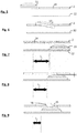
- FIG. 1 to 4 An example of launching arm 9 is shown in Figures 1 to 4 with an axis of rotation 11 around which the arm is rotatably mounted when actuated to launch a target 13.
- a front portion of the throwing arm provides contact with a target 13.
- the throwing arm 9 can have a configuration substantially elongated between a proximal end at which the axis of rotation 11 is located and a distal end.
- the angular displacement of the throwing arm 9 is made partly above a receiving surface 12 at which at least one target 13 can be loaded so as to produce the launch.
- the distance offset along the axis of rotation 11 between the throwing arm 9 and the receiving surface 12 is adjusted so that the throwing arm 9 is applied to the edge of the target 13 to be projected.
- the receiving surface 12 is perpendicular to the axis of rotation 11.
- the actuating system of the throwing arm 9 operates in a cyclic manner so that, after the relaxation of the spring, the throwing arm 9 is brought from a rest position to a rearmed position by the intervention of the engine 7.
- the machine advantageously comprises a barrel 3 at which a plurality of targets 13 can be stored. More specifically, the barrel 3 comprises a plurality of columns 4, these columns extending in parallel with each other and being organized in an annular sector, at the periphery of the barrel 3, about an axis 10.
- the number of columns 4 is not limited.
- Each column 4 is for example delimited by rods 5 extending along the axis 10 and serving as a lateral abutment surface to the targets 13 which are stacked in each of the columns 4. Thus sets of targets 13 are superimposed on each other.
- an upper frame 6b is advantageously positioned to connect together all the distal ends of the rods 5.
- the barrel 3 advantageously comprises a lower frame having the same function as the upper frame but to connect the proximal ends of the stems 5.
- the terms "inferior” and “superior” are, unless otherwise provided in this description, to mean a relative position of parts as compared to the action of gravity in the moving targets 13.
- the lower frame 6a defines openings for each column 4 so that a target 13 placed in the lowest position in a column 4 can be extracted from the barrel 3 by its lower end.
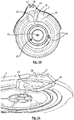
- a support 2 allowing the retention of the targets 13 in the columns 4, opposing the gravity.
- the support 2 comprises a retention surface 8, for example in the form of two annular portions extending along the path of the columns 4 about the axis 10 so as to produce a localized support of the lower face of the targets 13 placed in the lowest position of each column 4.
- the retention surface 8 advantageously does not extend along the entire angular movement of the support 2 so as to leave a lower level portion than that of the surfaces Retention 8 at the support 2.
- This part is illustrated as a transfer zone 19 at the level of the figure 10 .
- the barrel 3 is rotatably mounted about the axis 10 so that the columns 4 are advanced progressively according to this rotational movement.
- the rotational movement of the barrel 3 around the axis 10 is carried out sequentially with a step corresponding to 360 ° divided by the number of columns.
- the sequential movement of the barrel 3 is coupled to that of the throwing arm 9 so as to use a common motor for these two kinematics.
- each launching cycle of the arm 9 generates a movement of the barrel 3 sequentially by a determined step as a function of the number of columns 4.
- the support 2 comprises, as shown in particular in figure 10 , a hole 14 through which a target 13 can pass from a column 4 of the barrel 3 to the receiving surface 12.
- the hole 14 is located on the trajectory of the columns 4 so that successively one of the columns 4 comes, at the level of its lower end, opposite the hole 14. In this way, the target 13 located lowest in column 4 in hole 14 can cross the latter and move to the receiving surface 12. During this movement, a retention system of the other targets 13 of the column 4 in question is provided.
- the target 13 which is located lowest in one of the columns 4 moves during the successive movements of rotation of the barrel 3 around the axis 10, the target 13 being retained, against of its gravity, by the retention surfaces 8.
- the latter is advantageously located at a lower height level than the retention surfaces 8.
- These latter surfaces 8 may also be organized in the form of a ramp so that the level of the target 13 considered decreases progressively toward the transfer zone 19.
- the target 13 is shifted relatively to the rest of the stack of targets in the column 4 considered and continues its movement, in the trigonometric direction, towards the hole 14. At this level, the target 13 passes through the hole 14 and is found by its fall on the receiving surface 12. This mechanism is illustrated in Figures 5 and 6 .
- the target 13 is located on the transfer zone 19 and, continuing to be driven by the rotation of the barrel 3, gradually arrives at the hole 14.
- the target 13 passes through the latter as represented in figure 6 .
- the target 13 thus passes from the support 2 to the reception surface 12.
- FIG. figure 7 The result obtained is illustrated in FIG. figure 7 .
- Figures 5 to 7 illustrates this advance of the target 13 and its descent on the receiving surface 12 and further schematically an offset between the situation of the target 13 at the end of its path, resting on the receiving surface 12 relative to the edge of the hole 14
- the figure 7 shows a distance L 1 between the upstream edge of the hole 14 relative to the direction of rotation of the barrel 3 and the upstream edge of the edge of the target 13 on the receiving surface 12.
- the distance L 1 reflects that the kinetic energy of the target 13 has generated a shift relative to the right of the hole 14 so that the target 13 is not exactly opposite the hole 14 at the end of its transfer movement.
- the offset between the support 2 and the receiving surface 12 is very small, in the direction of the axis of rotation 10, so as to produce a significant decrease in the lateral offset between the hole 14 and the upstream edge of the target 13.
- the effect of this distance reduction between the support 2 and the receiving surface 12 is illustrated in FIG. figure 8 with a lag L 2 greatly decreased.
- the offset between the support 2 at the hole 14 and the receiving surface 12 is such that the residual clearance between the lower surface of the support 2 and the upper surface of the target 13 positioned on the receiving surface 12 is less than at 3 mm and preferably less than 2 mm. This dimension is marked "e" in figure 8 .
- the height of the target 13 may be of the order of 20 to 30 mm and for example of the order of 25 mm.
- An offset of 27 mm between the lower face of the support 2 at the area of the hole 14 and the upper face of the receiving surface 12 provides a residual clearance "e" of 2 mm.
- the offset can be set at the manufacturing stage.
- an offset adjustment system may be incorporated.
- the present invention may have, at the hole 14, a deflector 16 configured to limit the movement component of the target 13 passing through the hole 14 directed in the plane of the support 2.
- the deflector 16 has a configuration allowing a support on an area of the outer periphery of the target 13 to force the displacement the target 13 downwards, that is to say along the axis of rotation 10.
- the deflector 16 promotes the component of movements along the axis of rotation 10 for the target 13 by opposing the component perpendicular thereto by the support on the deflector 16.
- the deflector 16 comprises an inclined flat surface, this inclination going out of the hole 14 when passing from the support 2 to the receiving surface 12.
- An example of e deflector 16 is presented in figure 9 .
- the situation of the latter on the support 2 appears in particular in figure 10 , in which figure the deflector 16 is situated at the edge of the hole 14.
- figure 11 shows another view of the deflector 16 in bottom view of the support 2.
- the inclination of the deflector is preferably between 30 ° and 60 ° and in particular 45 °.
- the deflector limits the advance of the target 13 on the receiving surface 12 during its fall.
- the offset between the hole 14 and the target 13 is still limited as reflected by the distance L 3 represented in FIG. figure 9 .
- both the baffle 16 and the approach between the receiving surface 12 and the support 2 are taken advantage of.
- this adjustment capacity can be used to produce indifferently thanks to the invention a machine capable of launching targets by the right or left.
- the figures 1 and 3 show a first mode of use of the machine of the invention wherein the throwing arm 9 is mounted so as to have a rotation in a clockwise direction, the barrel 3 operating in the trigonometric direction.
- the figures 2 and 4 illustrate another mode of use of the machine of the invention in which the barrel 3 continues to rotate in the counterclockwise direction but in which the throwing arm 9 rotates in the trigonometric direction and no longer in the clockwise direction.
- the targets are projected by the left of the machine while they are projected by the right in the case of figures 2 and 4 .
- the present invention requires only slight modifications and in particular preferably the inversion of the launching arm 9 and the receiving surface 12.
- the present invention does not imply a modification of the system for storing and loading the targets on the receiving surface 12 and in particular the barrel 3 is not modified.
- the barrel 3 continues to rotate in the same direction.
- At least one of the previously described aspects relating to the height difference between the support 2 and the receiving surface 12 and the presence of a deflector 16 is implemented so that, whatever the direction of rotation of the launching arm 9, the target 13 is brought on the receiving surface 12 almost from the hole 14 so that the inversion of the direction of rotation of the arm 9 does not influence the launch of the target 13.
- the present invention may include a capacity of adjustment of the machine so as to modify the relative angular position between the support 2 and the frame 1 and compensate for the effect of the change of rotation of the arm 9.
- the support 2 is mountable on the frame 1 between a first position and at least a second position, these two positions having an angular offset along the axis of rotation 10 of the barrel or an axis which is parallel thereto.
- the latter preferably comprises a first anchoring zone 17 and at least a second anchoring zone 18 at which the support 2 can alternatively be fixed on the frame 1.
- the first and second anchoring zones 17, 18 may be holes passing through the support 2 and making it possible to constitute a point of attachment of the support 2 relative to the frame 1.
- an oblong hole or another Continuous adjustment mode of the bracket angle may be suitable.
- it also takes advantage of the holes 17, 18, to carry out the mounting of the axis of rotation 11 of the arm 9.
- two alternative positions are set to adjust the angular offset between the support 2 and the frame 1 while mounting the throwing arm 9 to rotate.
- rotation axis 10 of the barrel is advantageously parallel to the axis of rotation 11 of the arm.
- angular displacement between the support 2 and the frame 1 operates around an axis parallel to the two previous ones.
- the pivot of the support 2 between the two angular positions preferably operates along an axis parallel to that of rotation of the barrel 3.
- the figure 10 shows an example of location of the pivot axis 20 of the support 2.
- the result of the invention is particularly surprising insofar as although using a barrel 3 always rotating in the same direction of rotation, one can realize two machine configurations (rotation of the trigger arm 9 trigonometric or hourly) without to disturb the direction of the shot.
- two machine configurations rotation of the trigger arm 9 trigonometric or hourly
- the firing direction is unchanged in that the trajectories from these two modes of operation of the machine are parallel.
- the effect of the shift of the target 13 during its fall on the reception surface 12 has thus been completely annihilated.
Landscapes
- Engineering & Computer Science (AREA)
- General Engineering & Computer Science (AREA)
- Automatic Assembly (AREA)
- Transmission Devices (AREA)
- Aiming, Guidance, Guns With A Light Source, Armor, Camouflage, And Targets (AREA)
- Coating Apparatus (AREA)
Claims (14)
- Zielwurfmaschine (13), einen Grundrahmen (1) beinhaltend, auf dem eine Halterung (2) montiert ist, relativ zu der eine Trommel (3) gemäß einer Drehachse (10) drehend montiert ist, wobei die Trommel (3) eine Vielzahl von Säulen (4) zum gestapelten Bevorraten von Zielen (13) umfasst, wobei die Säulen (4) jeweils eine Längsachse parallel zur Drehachse (10) aufweisen, wobei der Grundrahmen (1) eine Oberfläche zur Aufnahme (12) von Zielen (13) im Hinblick auf einen Wurf umfasst, wobei die Halterung (2) ein Loch (14) beinhaltet, das konfiguriert ist, um den Durchlass eines Ziels (13) aus einer Säule (4) der Trommel (3) zu der Oberfläche zur Aufnahme (12) zuzulassen,
dadurch gekennzeichnet, dass die Halterung (2) eine erste Befestigungsposition relativ zum Grundrahmen (1) beinhaltet, und mindestens eine zweite Befestigungsposition relativ zum Grundrahmen (1), wobei die erste Position und die zweite Position einen Winkelversatz entlang der Drehachse (10) aufweisen. - Maschine nach dem vorstehenden Anspruch, wobei der Winkelversatz zwischen 2° und 15° enthalten ist.
- Maschine nach einem der vorstehenden Ansprüche, wobei eine Schwenkverbindung zwischen der Halterung (2) und dem Grundrahmen (1) entlang der Drehachse (10) und ein System zum Anhalten der Bewegung der Halterung entlang der Schwenkverbindung in jeder der ersten Position und der zweiten Position.
- Maschine nach einem der vorstehenden Ansprüche, wobei der Abstand in der Richtung der Drehachse (10), welche das Loch (14) und die Oberfläche zur Aufnahme (12) trennt, derart konfiguriert ist, dass das Restspiel (e) zwischen einer oberen Oberfläche eines Ziels (13), das auf der Oberfläche zur Aufnahme (12) platziert ist, und einer unteren Oberfläche (2) gegenüber dem Ziel (13) kleiner als 3 mm ist.
- Maschine nach einem der vorstehenden Ansprüche, wobei die Halterung (2) und die Oberfläche zur Aufnahme (12) parallel sind.
- Maschine nach einem der vorstehenden Ansprüche, einen Abweiser (16) beinhaltend, der konfiguriert ist, um ein Ziel (13) zu leiten, welches durch das Loch (14) zu der Oberfläche zur Aufnahme (12) durchführt.
- Maschine nach dem vorstehenden Anspruch, wobei der Abweiser (16) eine geneigte Seite relativ zu der Richtung der Drehachse (10) beinhaltet, die sich am Rand des Loches (14) befindet.
- Maschine nach dem vorstehenden Anspruch, wobei die geneigte Seite um einen Winkel zwischen 30 und 60° relativ zur Richtung der Drehachse (10) geneigt ist, wobei sie sich von der Mitte des Loches (14) in Richtung der Oberfläche zur Aufnahme (12) entfernt.
- Maschine nach einem der vorstehenden Ansprüche, einen Wurfarm (9) eines Ziels (13) beinhaltend, der auf der Oberfläche zur Aufnahme (12) positioniert ist, wobei der Arm (9) derart drehend montiert ist, dass er entlang zweier Drehrichtungen umkehrbar ist.
- Maschine nach dem vorstehenden Anspruch, eine Kopplungsvorrichtung umfassend, die konfiguriert ist, um eine Drehung der Trommel (3) gemäß einer einzigen Drehrichtung bei der Drehung des Armes (9) in eine der beiden Drehrichtungen zu erzeugen.
- Maschine nach einem der beiden vorstehenden Ansprüche, wobei die Oberfläche zur Aufnahme (12) in einer ersten Position auf dem Grundrahmen (1) montiert ist, wenn der Arm (9) in einer ersten Drehrichtung montiert ist, und in einer zweiten Position, wenn der Arm (9) in einer zweiten Drehrichtung drehend montiert ist.
- Verfahren zum Einstellen einer Wurfmaschine nach einem der vorstehenden Ansprüche, wobei man die Wurfrichtung eines Ziels (13) durch Auswählen einer der ersten Position und der zweiten Position der Halterung (2) einstellt.
- Verfahren nach dem vorstehenden Anspruch, zum Einstellen einer Maschine nach einem der Ansprüche 9 bis 11, wobei man die erste Position der Halterung (2) auswählt, wenn der Arm (9) in die erste Drehrichtung drehend montiert ist, und die zweite Position, wenn der Arm (9) in die zweite Drehrichtung drehend montiert ist.
- Verfahren nach dem vorstehenden Anspruch, wobei man die erste Position und die zweite Position der Halterung (2) derart definiert, um eine selbe Zielwurfrichtung (13) in der ersten und zweiten Drehrichtung des Arms (9) zu erzeugen.
Priority Applications (1)
| Application Number | Priority Date | Filing Date | Title |
|---|---|---|---|
| PL15807878T PL3234494T3 (pl) | 2014-12-17 | 2015-12-09 | Maszyna do wyrzucania rzutków i sposób jej regulowania |
Applications Claiming Priority (2)
| Application Number | Priority Date | Filing Date | Title |
|---|---|---|---|
| FR1462607A FR3030714B1 (fr) | 2014-12-17 | 2014-12-17 | Machine pour le lancement de cibles et son procede de reglage |
| PCT/EP2015/079056 WO2016096552A1 (fr) | 2014-12-17 | 2015-12-09 | Machine pour le lancement de cibles et son procédé de réglage |
Publications (2)
| Publication Number | Publication Date |
|---|---|
| EP3234494A1 EP3234494A1 (de) | 2017-10-25 |
| EP3234494B1 true EP3234494B1 (de) | 2018-11-07 |
Family
ID=52450509
Family Applications (1)
| Application Number | Title | Priority Date | Filing Date |
|---|---|---|---|
| EP15807878.2A Active EP3234494B1 (de) | 2014-12-17 | 2015-12-09 | Zielwurfmaschine und einstellverfahren dafür |
Country Status (5)
| Country | Link |
|---|---|
| US (1) | US9945644B2 (de) |
| EP (1) | EP3234494B1 (de) |
| FR (1) | FR3030714B1 (de) |
| PL (1) | PL3234494T3 (de) |
| WO (1) | WO2016096552A1 (de) |
Families Citing this family (2)
| Publication number | Priority date | Publication date | Assignee | Title |
|---|---|---|---|---|
| FR3095856B1 (fr) * | 2019-05-10 | 2021-05-21 | Laporte Holding | Machine de lancement de cibles |
| US10859349B1 (en) * | 2019-12-18 | 2020-12-08 | Cheh-Kang Liu | Micro switch adjustment structure of a throwing trap |
Family Cites Families (4)
| Publication number | Priority date | Publication date | Assignee | Title |
|---|---|---|---|---|
| US2711726A (en) * | 1952-05-10 | 1955-06-28 | George H Darrell | Target throwing machine |
| FR2728067A1 (fr) | 1994-12-13 | 1996-06-14 | Laporte Ball Trap | Appareil pour le lancement en double de cibles dites pigeons d'argile |
| US6431161B1 (en) * | 2001-02-20 | 2002-08-13 | Gosta Gustafssons Mekaniska Verstad Ab | Device for throwing targets |
| FR2993047B1 (fr) * | 2012-07-03 | 2015-04-10 | Laporte Holding | Dispositif de lancement de cibles pour le tir sportif a depart instantane de la cible |
-
2014
- 2014-12-17 FR FR1462607A patent/FR3030714B1/fr not_active Expired - Fee Related
-
2015
- 2015-12-09 EP EP15807878.2A patent/EP3234494B1/de active Active
- 2015-12-09 US US15/537,044 patent/US9945644B2/en not_active Expired - Fee Related
- 2015-12-09 PL PL15807878T patent/PL3234494T3/pl unknown
- 2015-12-09 WO PCT/EP2015/079056 patent/WO2016096552A1/fr active Application Filing
Non-Patent Citations (1)
| Title |
|---|
| None * |
Also Published As
| Publication number | Publication date |
|---|---|
| WO2016096552A1 (fr) | 2016-06-23 |
| US9945644B2 (en) | 2018-04-17 |
| PL3234494T3 (pl) | 2019-06-28 |
| US20180010893A1 (en) | 2018-01-11 |
| EP3234494A1 (de) | 2017-10-25 |
| FR3030714A1 (fr) | 2016-06-24 |
| FR3030714B1 (fr) | 2017-01-13 |
Similar Documents
| Publication | Publication Date | Title |
|---|---|---|
| EP2567178B1 (de) | Zielabschussvorrichtung | |
| EP2952236B1 (de) | Federbelasteter spann-/entspannmechanismus, und hüpfspielzeug, das diesen mechanismus umfasst | |
| CA2821369A1 (fr) | Machine de lancement de cibles | |
| EP0592344B1 (de) | Abschussvorrichtung für Tontauben | |
| EP3234494B1 (de) | Zielwurfmaschine und einstellverfahren dafür | |
| FR3066813A1 (fr) | Machine de lancement de cibles a orientation variable | |
| WO2013023960A1 (fr) | Machine de lancement de cibles pour le tir à l'arc à chargement par gravité | |
| EP2567181B1 (de) | Zielabschussvorrichtung | |
| WO2020229322A1 (fr) | Machine de lancement de cibles | |
| EP1319162A1 (de) | Zielschleuder mit einem einstellbaren abschiesswinkel | |
| FR3076608A1 (fr) | Machine de lancement de cibles a chargement par gravite | |
| EP3818327A1 (de) | Maschine zum abschuss von zielen mit drehzylinder | |
| EP3403046B1 (de) | Zielwurfmaschine mit verbessertem magazin | |
| EP4031828B1 (de) | Zielabschussvorrichtung | |
| FR2787181A1 (fr) | Appareil pour le lancement de cibles du type plateau d'argile | |
| FR2696538A1 (fr) | Perfectionnement lié aux appareils pour le lancement de plateaux ou cibles mobiles. | |
| WO2023151906A1 (fr) | Base pour machine de lancement de cibles | |
| WO2012080491A1 (fr) | Dispositif pour lancer des cibles pour le tir | |
| WO2018146243A1 (fr) | Appareil de lancement de cibles comprenant un organe de repositionnement des cibles avant lancement | |
| FR2733043A1 (fr) | Appareil pour le lancement de plateaux ou cibles mobiles pour le tir sportif | |
| FR3062230A1 (fr) | Machine de tri et de comptage | |
| FR2955176A1 (fr) | Systeme comprenant un dispositif pour le lancement automatique de cible en mousse de polymere | |
| WO2013004599A1 (fr) | Machine de lancement de cibles pour le tir à l'arc à goulotte de chargement |
Legal Events
| Date | Code | Title | Description |
|---|---|---|---|
| STAA | Information on the status of an ep patent application or granted ep patent |
Free format text: STATUS: THE INTERNATIONAL PUBLICATION HAS BEEN MADE |
|
| PUAI | Public reference made under article 153(3) epc to a published international application that has entered the european phase |
Free format text: ORIGINAL CODE: 0009012 |
|
| STAA | Information on the status of an ep patent application or granted ep patent |
Free format text: STATUS: REQUEST FOR EXAMINATION WAS MADE |
|
| 17P | Request for examination filed |
Effective date: 20170711 |
|
| AK | Designated contracting states |
Kind code of ref document: A1 Designated state(s): AL AT BE BG CH CY CZ DE DK EE ES FI FR GB GR HR HU IE IS IT LI LT LU LV MC MK MT NL NO PL PT RO RS SE SI SK SM TR |
|
| AX | Request for extension of the european patent |
Extension state: BA ME |
|
| DAV | Request for validation of the european patent (deleted) | ||
| DAX | Request for extension of the european patent (deleted) | ||
| GRAP | Despatch of communication of intention to grant a patent |
Free format text: ORIGINAL CODE: EPIDOSNIGR1 |
|
| STAA | Information on the status of an ep patent application or granted ep patent |
Free format text: STATUS: GRANT OF PATENT IS INTENDED |
|
| INTG | Intention to grant announced |
Effective date: 20180606 |
|
| GRAS | Grant fee paid |
Free format text: ORIGINAL CODE: EPIDOSNIGR3 |
|
| GRAA | (expected) grant |
Free format text: ORIGINAL CODE: 0009210 |
|
| STAA | Information on the status of an ep patent application or granted ep patent |
Free format text: STATUS: THE PATENT HAS BEEN GRANTED |
|
| AK | Designated contracting states |
Kind code of ref document: B1 Designated state(s): AL AT BE BG CH CY CZ DE DK EE ES FI FR GB GR HR HU IE IS IT LI LT LU LV MC MK MT NL NO PL PT RO RS SE SI SK SM TR |
|
| REG | Reference to a national code |
Ref country code: GB Ref legal event code: FG4D Free format text: NOT ENGLISH |
|
| REG | Reference to a national code |
Ref country code: CH Ref legal event code: EP Ref country code: AT Ref legal event code: REF Ref document number: 1062572 Country of ref document: AT Kind code of ref document: T Effective date: 20181115 |
|
| REG | Reference to a national code |
Ref country code: DE Ref legal event code: R096 Ref document number: 602015019657 Country of ref document: DE |
|
| REG | Reference to a national code |
Ref country code: IE Ref legal event code: FG4D Free format text: LANGUAGE OF EP DOCUMENT: FRENCH |
|
| REG | Reference to a national code |
Ref country code: NL Ref legal event code: MP Effective date: 20181107 |
|
| REG | Reference to a national code |
Ref country code: LT Ref legal event code: MG4D |
|
| REG | Reference to a national code |
Ref country code: AT Ref legal event code: MK05 Ref document number: 1062572 Country of ref document: AT Kind code of ref document: T Effective date: 20181107 |
|
| PG25 | Lapsed in a contracting state [announced via postgrant information from national office to epo] |
Ref country code: ES Free format text: LAPSE BECAUSE OF FAILURE TO SUBMIT A TRANSLATION OF THE DESCRIPTION OR TO PAY THE FEE WITHIN THE PRESCRIBED TIME-LIMIT Effective date: 20181107 Ref country code: LV Free format text: LAPSE BECAUSE OF FAILURE TO SUBMIT A TRANSLATION OF THE DESCRIPTION OR TO PAY THE FEE WITHIN THE PRESCRIBED TIME-LIMIT Effective date: 20181107 Ref country code: HR Free format text: LAPSE BECAUSE OF FAILURE TO SUBMIT A TRANSLATION OF THE DESCRIPTION OR TO PAY THE FEE WITHIN THE PRESCRIBED TIME-LIMIT Effective date: 20181107 Ref country code: BG Free format text: LAPSE BECAUSE OF FAILURE TO SUBMIT A TRANSLATION OF THE DESCRIPTION OR TO PAY THE FEE WITHIN THE PRESCRIBED TIME-LIMIT Effective date: 20190207 Ref country code: NO Free format text: LAPSE BECAUSE OF FAILURE TO SUBMIT A TRANSLATION OF THE DESCRIPTION OR TO PAY THE FEE WITHIN THE PRESCRIBED TIME-LIMIT Effective date: 20190207 Ref country code: FI Free format text: LAPSE BECAUSE OF FAILURE TO SUBMIT A TRANSLATION OF THE DESCRIPTION OR TO PAY THE FEE WITHIN THE PRESCRIBED TIME-LIMIT Effective date: 20181107 Ref country code: LT Free format text: LAPSE BECAUSE OF FAILURE TO SUBMIT A TRANSLATION OF THE DESCRIPTION OR TO PAY THE FEE WITHIN THE PRESCRIBED TIME-LIMIT Effective date: 20181107 Ref country code: AT Free format text: LAPSE BECAUSE OF FAILURE TO SUBMIT A TRANSLATION OF THE DESCRIPTION OR TO PAY THE FEE WITHIN THE PRESCRIBED TIME-LIMIT Effective date: 20181107 Ref country code: IS Free format text: LAPSE BECAUSE OF FAILURE TO SUBMIT A TRANSLATION OF THE DESCRIPTION OR TO PAY THE FEE WITHIN THE PRESCRIBED TIME-LIMIT Effective date: 20190307 |
|
| PG25 | Lapsed in a contracting state [announced via postgrant information from national office to epo] |
Ref country code: SE Free format text: LAPSE BECAUSE OF FAILURE TO SUBMIT A TRANSLATION OF THE DESCRIPTION OR TO PAY THE FEE WITHIN THE PRESCRIBED TIME-LIMIT Effective date: 20181107 Ref country code: NL Free format text: LAPSE BECAUSE OF FAILURE TO SUBMIT A TRANSLATION OF THE DESCRIPTION OR TO PAY THE FEE WITHIN THE PRESCRIBED TIME-LIMIT Effective date: 20181107 Ref country code: RS Free format text: LAPSE BECAUSE OF FAILURE TO SUBMIT A TRANSLATION OF THE DESCRIPTION OR TO PAY THE FEE WITHIN THE PRESCRIBED TIME-LIMIT Effective date: 20181107 Ref country code: PT Free format text: LAPSE BECAUSE OF FAILURE TO SUBMIT A TRANSLATION OF THE DESCRIPTION OR TO PAY THE FEE WITHIN THE PRESCRIBED TIME-LIMIT Effective date: 20190307 Ref country code: GR Free format text: LAPSE BECAUSE OF FAILURE TO SUBMIT A TRANSLATION OF THE DESCRIPTION OR TO PAY THE FEE WITHIN THE PRESCRIBED TIME-LIMIT Effective date: 20190208 Ref country code: AL Free format text: LAPSE BECAUSE OF FAILURE TO SUBMIT A TRANSLATION OF THE DESCRIPTION OR TO PAY THE FEE WITHIN THE PRESCRIBED TIME-LIMIT Effective date: 20181107 |
|
| REG | Reference to a national code |
Ref country code: DE Ref legal event code: R119 Ref document number: 602015019657 Country of ref document: DE |
|
| PG25 | Lapsed in a contracting state [announced via postgrant information from national office to epo] |
Ref country code: DK Free format text: LAPSE BECAUSE OF FAILURE TO SUBMIT A TRANSLATION OF THE DESCRIPTION OR TO PAY THE FEE WITHIN THE PRESCRIBED TIME-LIMIT Effective date: 20181107 Ref country code: CZ Free format text: LAPSE BECAUSE OF FAILURE TO SUBMIT A TRANSLATION OF THE DESCRIPTION OR TO PAY THE FEE WITHIN THE PRESCRIBED TIME-LIMIT Effective date: 20181107 Ref country code: IT Free format text: LAPSE BECAUSE OF FAILURE TO SUBMIT A TRANSLATION OF THE DESCRIPTION OR TO PAY THE FEE WITHIN THE PRESCRIBED TIME-LIMIT Effective date: 20181107 |
|
| REG | Reference to a national code |
Ref country code: CH Ref legal event code: PL |
|
| PG25 | Lapsed in a contracting state [announced via postgrant information from national office to epo] |
Ref country code: SM Free format text: LAPSE BECAUSE OF FAILURE TO SUBMIT A TRANSLATION OF THE DESCRIPTION OR TO PAY THE FEE WITHIN THE PRESCRIBED TIME-LIMIT Effective date: 20181107 Ref country code: SK Free format text: LAPSE BECAUSE OF FAILURE TO SUBMIT A TRANSLATION OF THE DESCRIPTION OR TO PAY THE FEE WITHIN THE PRESCRIBED TIME-LIMIT Effective date: 20181107 Ref country code: MC Free format text: LAPSE BECAUSE OF FAILURE TO SUBMIT A TRANSLATION OF THE DESCRIPTION OR TO PAY THE FEE WITHIN THE PRESCRIBED TIME-LIMIT Effective date: 20181107 Ref country code: EE Free format text: LAPSE BECAUSE OF FAILURE TO SUBMIT A TRANSLATION OF THE DESCRIPTION OR TO PAY THE FEE WITHIN THE PRESCRIBED TIME-LIMIT Effective date: 20181107 Ref country code: LU Free format text: LAPSE BECAUSE OF NON-PAYMENT OF DUE FEES Effective date: 20181209 Ref country code: RO Free format text: LAPSE BECAUSE OF FAILURE TO SUBMIT A TRANSLATION OF THE DESCRIPTION OR TO PAY THE FEE WITHIN THE PRESCRIBED TIME-LIMIT Effective date: 20181107 |
|
| PLBE | No opposition filed within time limit |
Free format text: ORIGINAL CODE: 0009261 |
|
| STAA | Information on the status of an ep patent application or granted ep patent |
Free format text: STATUS: NO OPPOSITION FILED WITHIN TIME LIMIT |
|
| REG | Reference to a national code |
Ref country code: IE Ref legal event code: MM4A |
|
| REG | Reference to a national code |
Ref country code: BE Ref legal event code: MM Effective date: 20181231 |
|
| 26N | No opposition filed |
Effective date: 20190808 |
|
| PG25 | Lapsed in a contracting state [announced via postgrant information from national office to epo] |
Ref country code: DE Free format text: LAPSE BECAUSE OF NON-PAYMENT OF DUE FEES Effective date: 20190702 Ref country code: IE Free format text: LAPSE BECAUSE OF NON-PAYMENT OF DUE FEES Effective date: 20181209 Ref country code: SI Free format text: LAPSE BECAUSE OF FAILURE TO SUBMIT A TRANSLATION OF THE DESCRIPTION OR TO PAY THE FEE WITHIN THE PRESCRIBED TIME-LIMIT Effective date: 20181107 |
|
| PG25 | Lapsed in a contracting state [announced via postgrant information from national office to epo] |
Ref country code: BE Free format text: LAPSE BECAUSE OF NON-PAYMENT OF DUE FEES Effective date: 20181231 |
|
| PG25 | Lapsed in a contracting state [announced via postgrant information from national office to epo] |
Ref country code: CH Free format text: LAPSE BECAUSE OF NON-PAYMENT OF DUE FEES Effective date: 20181231 Ref country code: LI Free format text: LAPSE BECAUSE OF NON-PAYMENT OF DUE FEES Effective date: 20181231 |
|
| PG25 | Lapsed in a contracting state [announced via postgrant information from national office to epo] |
Ref country code: MT Free format text: LAPSE BECAUSE OF FAILURE TO SUBMIT A TRANSLATION OF THE DESCRIPTION OR TO PAY THE FEE WITHIN THE PRESCRIBED TIME-LIMIT Effective date: 20181107 |
|
| PGFP | Annual fee paid to national office [announced via postgrant information from national office to epo] |
Ref country code: PL Payment date: 20191120 Year of fee payment: 5 |
|
| PG25 | Lapsed in a contracting state [announced via postgrant information from national office to epo] |
Ref country code: TR Free format text: LAPSE BECAUSE OF FAILURE TO SUBMIT A TRANSLATION OF THE DESCRIPTION OR TO PAY THE FEE WITHIN THE PRESCRIBED TIME-LIMIT Effective date: 20181107 |
|
| PG25 | Lapsed in a contracting state [announced via postgrant information from national office to epo] |
Ref country code: HU Free format text: LAPSE BECAUSE OF FAILURE TO SUBMIT A TRANSLATION OF THE DESCRIPTION OR TO PAY THE FEE WITHIN THE PRESCRIBED TIME-LIMIT; INVALID AB INITIO Effective date: 20151209 Ref country code: CY Free format text: LAPSE BECAUSE OF FAILURE TO SUBMIT A TRANSLATION OF THE DESCRIPTION OR TO PAY THE FEE WITHIN THE PRESCRIBED TIME-LIMIT Effective date: 20181107 Ref country code: MK Free format text: LAPSE BECAUSE OF NON-PAYMENT OF DUE FEES Effective date: 20181107 |
|
| PGFP | Annual fee paid to national office [announced via postgrant information from national office to epo] |
Ref country code: PL Payment date: 20200618 Year of fee payment: 5 |
|
| PG25 | Lapsed in a contracting state [announced via postgrant information from national office to epo] |
Ref country code: PL Free format text: LAPSE BECAUSE OF NON-PAYMENT OF DUE FEES Effective date: 20201209 |
|
| PGFP | Annual fee paid to national office [announced via postgrant information from national office to epo] |
Ref country code: GB Payment date: 20231221 Year of fee payment: 9 |
|
| PGFP | Annual fee paid to national office [announced via postgrant information from national office to epo] |
Ref country code: FR Payment date: 20231220 Year of fee payment: 9 |
|
| P01 | Opt-out of the competence of the unified patent court (upc) registered |
Effective date: 20240318 |