EP3234494B1 - Target-throwing machine, and the adjustment method thereof - Google Patents
Target-throwing machine, and the adjustment method thereof Download PDFInfo
- Publication number
- EP3234494B1 EP3234494B1 EP15807878.2A EP15807878A EP3234494B1 EP 3234494 B1 EP3234494 B1 EP 3234494B1 EP 15807878 A EP15807878 A EP 15807878A EP 3234494 B1 EP3234494 B1 EP 3234494B1
- Authority
- EP
- European Patent Office
- Prior art keywords
- rotation
- target
- support
- arm
- machine according
- Prior art date
- Legal status (The legal status is an assumption and is not a legal conclusion. Google has not performed a legal analysis and makes no representation as to the accuracy of the status listed.)
- Active
Links
- 238000000034 method Methods 0.000 title claims description 6
- 230000033001 locomotion Effects 0.000 claims description 22
- 230000008878 coupling Effects 0.000 claims description 2
- 238000010168 coupling process Methods 0.000 claims description 2
- 238000005859 coupling reaction Methods 0.000 claims description 2
- 230000014759 maintenance of location Effects 0.000 description 8
- 230000000694 effects Effects 0.000 description 7
- 238000012546 transfer Methods 0.000 description 7
- 230000005484 gravity Effects 0.000 description 4
- 238000004873 anchoring Methods 0.000 description 3
- 238000006073 displacement reaction Methods 0.000 description 3
- 238000011144 upstream manufacturing Methods 0.000 description 3
- 241000272201 Columbiformes Species 0.000 description 2
- 230000008901 benefit Effects 0.000 description 2
- 230000008859 change Effects 0.000 description 2
- 239000004927 clay Substances 0.000 description 2
- 230000007423 decrease Effects 0.000 description 2
- 238000013461 design Methods 0.000 description 2
- 238000004519 manufacturing process Methods 0.000 description 2
- 230000004048 modification Effects 0.000 description 2
- 238000012986 modification Methods 0.000 description 2
- 230000009471 action Effects 0.000 description 1
- 238000013459 approach Methods 0.000 description 1
- 230000005540 biological transmission Effects 0.000 description 1
- 125000004122 cyclic group Chemical group 0.000 description 1
- 230000003247 decreasing effect Effects 0.000 description 1
- 238000005516 engineering process Methods 0.000 description 1
- 238000010304 firing Methods 0.000 description 1
- 230000003100 immobilizing effect Effects 0.000 description 1
- 230000000670 limiting effect Effects 0.000 description 1
- 230000007246 mechanism Effects 0.000 description 1
- 239000002184 metal Substances 0.000 description 1
- 239000003607 modifier Substances 0.000 description 1
- 230000009467 reduction Effects 0.000 description 1
- 230000000284 resting effect Effects 0.000 description 1
- 230000000717 retained effect Effects 0.000 description 1
Images


Classifications
-
- F—MECHANICAL ENGINEERING; LIGHTING; HEATING; WEAPONS; BLASTING
- F41—WEAPONS
- F41J—TARGETS; TARGET RANGES; BULLET CATCHERS
- F41J9/00—Moving targets, i.e. moving when fired at
- F41J9/16—Clay-pigeon targets; Clay-disc targets
- F41J9/18—Traps or throwing-apparatus therefor
- F41J9/30—Traps or throwing-apparatus therefor characterised by using a magazine of targets
-
- F—MECHANICAL ENGINEERING; LIGHTING; HEATING; WEAPONS; BLASTING
- F41—WEAPONS
- F41J—TARGETS; TARGET RANGES; BULLET CATCHERS
- F41J9/00—Moving targets, i.e. moving when fired at
- F41J9/16—Clay-pigeon targets; Clay-disc targets
- F41J9/18—Traps or throwing-apparatus therefor
-
- F—MECHANICAL ENGINEERING; LIGHTING; HEATING; WEAPONS; BLASTING
- F41—WEAPONS
- F41J—TARGETS; TARGET RANGES; BULLET CATCHERS
- F41J9/00—Moving targets, i.e. moving when fired at
- F41J9/16—Clay-pigeon targets; Clay-disc targets
- F41J9/18—Traps or throwing-apparatus therefor
- F41J9/20—Traps or throwing-apparatus therefor with spring-operated throwing arm
- F41J9/24—Traps or throwing-apparatus therefor with spring-operated throwing arm cocked by electromechanical means
Landscapes
- Engineering & Computer Science (AREA)
- General Engineering & Computer Science (AREA)
- Automatic Assembly (AREA)
- Coating Apparatus (AREA)
- Aiming, Guidance, Guns With A Light Source, Armor, Camouflage, And Targets (AREA)
- Transmission Devices (AREA)
Description
La présente invention concerne une machine de lancement de cibles ainsi qu'un procédé de réglage de cette machine.The present invention relates to a target launching machine and a method of adjusting this machine.
Elle trouve son application dans le domaine de la projection de cibles pour le tir du type ball-trap pour lequel on utilise des cibles sous forme de plateaux en forme de soucoupe souvent appelés pigeons d'argile.It finds its application in the field of the projection of targets for shooting the trap-type for which targets are used in the form of saucer-shaped trays often called clay pigeons.
On connaît des machines permettant le lancement de cibles depuis plusieurs décennies. Ces machines utilisent généralement un bras de lancement monté rotatif et armé, par exemple par un système de tension à ressort, de sorte que le déclenchement de la rotation du bras, sur commande, génère un vif mouvement du bras. Ce dernier intercepte une cible placée sur une surface de projection et la cible se trouve projetée à vive allure.Machines have been known to launch targets for several decades. These machines generally use a rotary arm mounted launch arm, for example by a spring tension system, so that the release of the rotation of the arm, on command, generates a sharp movement of the arm. The latter intercepts a target placed on a projection surface and the target is projected at high speed.
Dans les machines les plus évoluées, il est possible de lancer un grand nombre de cibles sans recharger la machine. A cet effet, la machine comporte un magasin de stockage de cibles, les cibles étant délivrées une par une vers la surface de projection. Une conception de magasin comprend un barillet disposant d'un mouvement de rotation. Le barillet incorpore une pluralité de colonnes permettant chacune de stocker plusieurs cibles en superposition. Le mouvement de rotation du barillet assure le positionnement séquentiel d'une des colonnes en regard d'un trou permettant la délivrance de la cible placée le plus bas dans la colonne, vers la surface de projection.In the most advanced machines, it is possible to launch a large number of targets without reloading the machine. For this purpose, the machine comprises a target storage magazine, the targets being delivered one by one to the projection surface. A store design includes a barrel having a rotational movement. The barrel incorporates a plurality of columns each for storing multiple targets in superposition. The rotational movement of the barrel ensures the sequential positioning of one of the columns facing a hole for the delivery of the lowest placed target in the column to the projection surface.
Généralement, la rotation séquentielle du barillet (dont le pas angulaire est fonction du nombre de colonnes) est couplée au cycle de rotation du bras, un cycle du bras engendrant un mouvement du barillet de sorte à placer une colonne suivante en regard du trou et ainsi, par ce mouvement circulaire, vider progressivement les colonnes du barillet.Generally, the sequential rotation of the barrel (whose angular pitch is a function of the number of columns) is coupled to the cycle of rotation of the arm, a cycle of the arm generating a movement of the barrel so as to place a next column next to the hole and thus by this circular movement, gradually empty the columns of the barrel.
Sur la base de cette technologie, on a cherché à offrir une variété de possibilité de tirs, de sorte à multiplier les configurations d'exercices du ball-trap. Une des possibilités consiste à varier le sens de rotation du bras de lancement de sorte à produire une projection par la droite ou par la gauche de la machine. On a ainsi proposé des machines pour lesquelles le bras, et de ce fait aussi le barillet, tournent dans le sens trigonométrique et, en complément des machines pour lesquelles le bras et le barillet tournent dans le sens horaire. Il ressort qu'il faut disposer de plusieurs machines spécifiques - au moins deux - pour s'offrir cette variété de tirs
Il existe un besoin pour permettre de variantes de lancement de cibles, en particulier avec des rotations différentes du bras sans pour autant engendrer une multiplication des coûts. Il existe aussi de manière générale un besoin pour régler la direction de projection des machines.There is a need to allow target launch variants, especially with different rotations of the arm without causing cost multiplication. There is also a general need to adjust the projection direction of the machines.
La présente invention concerne, suivant un aspect, une machine pour le lancement de cibles, comportant un châssis sur lequel est monté un support relativement auquel un barillet est monté rotatif suivant un axe de rotation, le barillet comprenant une pluralité de colonnes de stockage de cibles en empilement, les colonnes ayant chacune un axe longitudinal parallèle à l'axe de rotation, le châssis comprenant une surface de réception de cibles en vue d'un lancement, le support comportant un trou configuré pour autoriser le passage d'un cible depuis une colonne du barillet vers la surface de réception.The present invention relates, in one aspect, a machine for launching targets, comprising a frame on which is mounted a support relative to which a cylinder is rotatably mounted along an axis of rotation, the cylinder comprising a plurality of target storage columns in stack, the columns each having a longitudinal axis parallel to the axis of rotation, the frame comprising a target receiving surface for launching, the support having a hole configured to allow the passage of a target from a barrel column to the receiving surface.
Suivant un aspect avantageux, le support comporte une première position de fixation relativement au châssis, et au moins une deuxième position de fixation relativement au châssis, la première position et la deuxième position présentant un décalage angulaire suivant une direction parallèle à l'axe de rotation.According to an advantageous aspect, the support comprises a first fixing position relative to the frame, and at least a second fixing position relative to the frame, the first position and the second position having an angular offset in a direction parallel to the axis of rotation. .
On peut ainsi régler la direction de projection de la cible. C'est en particulier utile pour compenser les effets de l'inertie de la cible passant au travers du trou. Plus précisément, la cible en question passe au travers du trou en ayant auparavant subi une force, essentiellement tangentielle à la trajectoire du barillet, du fait de la rotation de ce dernier. La cible ne chute donc pas sur la surface de réception avec la seule application de son poids, mais aussi avec une composante liée à son inertie dans ce mouvement induit par la rotation du barillet. En pratique, la cible n'atteint pas la surface de réception au droit exact du trou, mais de façon un peu décalée.It is thus possible to adjust the projection direction of the target. This is particularly useful for compensating the effects of the inertia of the target passing through the hole. Specifically, the target in question passes through the hole having previously undergone a force, substantially tangential to the trajectory of the barrel, due to the rotation of the latter. The target does not fall on the receiving surface with the sole application of its weight, but also with a component related to its inertia in this movement induced by the rotation of the barrel. In practice, the target does not reach the receiving surface at the exact right of the hole, but slightly shifted.
La présence de deux positions angulaires pour le support permet de déplacer la position du trou pour tenir compte du décalage naturel de la cible. Une application de ce réglage est de permettre un fonctionnement de la machine soit dans un premier sens de rotation du bras, soit dans un sens opposé, tout en gardant le même sens de rotation du barillet (et donc en évitant de devoir concevoir et produire des barillets dédiés à un sens de rotation unique du bras). En pratique, grâce à l'invention, l'utilisateur peut employer la machine dans un sens de rotation du bras correspondant à celui du barillet, puis simplement monter le bras (et éventuellement la surface de réception) pour que le bras tourne en sens inverse et produise un lancement de cible d'un autre côté de la machine. Le barillet, quant à lui, reste en place et son sens de rotation n'est pas modifié. La position de la cible tombant sur la surface de réception est simplement corrigée en modifiant la position angulaire du support, de sorte à tenir compte du fait que le barillet et le bras tournent cette fois en sens inverse. On assure ainsi toujours une position de départ fixe de la cible relativement au bras, sur la surface de réception. Seul le sens de rotation du bras est modifié.The presence of two angular positions for the support makes it possible to move the position of the hole to take account of the natural shift of the target. One application of this adjustment is to allow operation of the machine either in a first direction of rotation of the arm, or in an opposite direction, while keeping the same direction of rotation of the barrel (and thus avoiding having to design and produce barrels dedicated to a unique direction of rotation of the arm). In practice, thanks to the invention, the user can use the machine in a direction of rotation of the arm corresponding to that of the barrel, then simply mount the arm (and possibly the receiving surface) so that the arm rotates in the opposite direction and produce a target launch on the other side of the machine. The barrel, meanwhile, remains in place and its direction of rotation is not changed. The position of the target falling on the receiving surface is simply corrected by changing the angular position of the support, so as to take account of the fact that the barrel and the arm turn this time in the opposite direction. This ensures a fixed starting position of the target relative to the arm, on the receiving surface. Only the direction of rotation of the arm is changed.
On dispose alors d'une machine évolutive à deux sens de rotation du bras en ajoutant simplement un ou plusieurs supports pour fixer la surface de réception et surtout en utilisant 100% des pièces de la machine d'origine; la fabrication est standardisée.It then has a scalable machine with two directions of rotation of the arm by simply adding one or more supports to fix the receiving surface and especially using 100% of the original machine parts; the manufacturing is standardized.
Le réglage d'une trajectoire s'obtient par un réglage angulaire du socle de la machine vis-à-vis de son support. C'est une opération très simple et très rapide. Modifier la position du barillet pour obtenir un effet similaire serait bien plus long à mettre en oeuvre surtout si la machine est remplie.The adjustment of a trajectory is obtained by an angular adjustment of the base of the machine vis-à-vis its support. It is a very simple operation and very fast. Changing the position of the barrel to achieve a similar effect would be much longer to implement especially if the machine is filled.
L'invention est aussi relative à un procédé.The invention is also related to a method.
L'invention sera mieux comprise au niveau des planches de dessins annexées à la présente qui présentent des modes de réalisation non limitatifs de l'invention sur les figures suivantes :
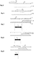
- La
figure 1 qui présente une vue en perspective d'un premier mode de réalisation de l'invention ; - La
figure 2 qui présente ce mode de réalisation de l'invention avec une réalisation symétrique du lancement de cibles ; - Les
figures 3 et 4 qui présentent respectivement des vues de dessus desfigures 1 et 2 ; - Les
figures 5 à 7 qui schématisent la cinématique d'une cible en cours de chargement avant son lancement par un bras de lancement ; - La
figure 8 qui présente un aspect de l'invention ; - La
figure 9 qui montre la possibilité de modifier la trajectoire d'une cible lors de son chargement avant lancement ; - La
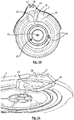
figure 10 qui montre une vue de dessus d'une pièce de support de l'invention ; - La
figure 11 qui présente un détail de la pièce de support.
- The
figure 1 which presents a perspective view of a first embodiment of the invention; - The
figure 2 which presents this embodiment of the invention with a symmetrical realization of the launch of targets; - The
Figures 3 and 4 which respectively show top views ofFigures 1 and 2 ; - The
Figures 5 to 7 which schematize the kinematics of a target being loaded before launch by a launching arm; - The
figure 8 which presents an aspect of the invention; - The
figure 9 which shows the possibility of modifying the trajectory of a target during its loading before launching; - The
figure 10 which shows a top view of a support piece of the invention; - The
figure 11 which presents a detail of the support piece.
Avant de décrire des modes de réalisation de l'invention, en particulier en référence aux dessins, on donne ci-après des options que l'invention peut éventuellement présenter selon toutes combinaisons éventuelles.
- le décalage angulaire est compris entre 2 et 15° et de préférence de 5°.
- la machine comporte une liaison pivot entre le support et le châssis suivant l'axe de rotation et un système d'immobilisation du mouvement du support selon la liaison pivot dans chacune parmi la première position et la deuxième position ;
- la distance suivant la direction de l'axe de rotation, séparant le trou et la surface de réception est configurée de sorte que le jeu résiduel (e) entre une surface supérieure d'une cible (13) placée sur la surface de réception (12) d'une surface inférieure du support (2) en vis-à-vis de la cible (13) soit inférieure ou égale à 3 mm ;
- le support (2) et la surface de réception (12) sont parallèles ;
- la machine comprend un déflecteur configuré pour guider une cible (13) passant au travers du trou vers la surface de réception (12) ;
- le déflecteur comporte un pan incliné relativement à la direction de l'axe de rotation, situé en bordure du trou ;
- le pan incliné est incliné d'un angle entre 30° et 60° et de préférence 45° relativement à la direction de l'axe de rotation, en s'éloignant du centre du trou en direction de la surface de réception ;
- un bras de lancement d'une cible positionnée sur la surface de réception est monté en rotation de manière à réversible, suivant deux sens de rotation ;
- un dispositif de couplage est configuré pour produire une rotation du barillet suivant un sens unique de rotation lors d'une rotation du bras suivant l'un parmi les deux sens de rotation ;
- la surface de réception est montée sur le châssis dans une première position lorsque le bras est monté suivant un premier sens de rotation, et dans une deuxième position lorsque le bras est monté rotatif suivant un deuxième sens de rotation.
- on règle la direction de lancement d'une cible en sélectionnant l'une parmi la première position et la deuxième position du support.
- on sélectionne la première position du support lorsque le bras est monté rotatif suivant le premier sens de rotation et la deuxième position lorsque le bras est monté rotatif suivant le deuxième sens de rotation ;
- on définit la première position et la deuxième position du support de sorte à produire une même direction de lancement de cible dans le premier et deuxième sens de rotation du bras.
- the angular offset is between 2 and 15 ° and preferably 5 °.
- the machine comprises a pivot connection between the support and the frame along the axis of rotation and a system for immobilizing the movement of the support according to the pivot connection in each of the first position and the second position;
- the distance in the direction of the axis of rotation separating the hole from the receiving surface is configured such that the residual clearance (e) between an upper surface of a target (13) placed on the receiving surface (12); ) a lower surface of the support (2) vis-à-vis the target (13) is less than or equal to 3 mm;
- the support (2) and the receiving surface (12) are parallel;
- the machine comprises a baffle configured to guide a target (13) passing through the hole to the receiving surface (12);
- the baffle comprises a sloping section relative to the direction of the axis of rotation, located at the edge of the hole;
- the inclined face is inclined at an angle between 30 ° and 60 ° and preferably 45 ° relative to the direction of the axis of rotation, away from the center of the hole towards the receiving surface;
- a launch arm of a target positioned on the receiving surface is rotatably mounted reversibly in two directions of rotation;
- a coupling device is configured to rotate the barrel in a single direction of rotation upon rotation of the arm in either of two directions of rotation;
- the receiving surface is mounted on the frame in a first position when the arm is mounted in a first direction of rotation, and in a second position when the arm is rotatably mounted in a second direction of rotation.
- setting the launch direction of a target by selecting one of the first position and the second position of the medium.
- the first position of the support is selected when the arm is rotatably mounted in the first direction of rotation and the second position when the arm is rotatably mounted in the second direction of rotation;
- defining the first position and the second position of the support so as to produce the same target launching direction in the first and second direction of rotation of the arm.
En référence à la
Le système d'actionnement du bras de lancement 9 fonctionne de manière cyclique de sorte que, après la détente du ressort, le bras de lancement 9 est ramené d'une position de repos à une position réarmée par l'intervention de la motorisation 7.The actuating system of the throwing
Une telle machine permet le lancement d'au moins une cible 13 au cours d'un tel mouvement. De sorte à rendre la machine autonome dans le lancement d'un grand nombre de cibles 13, la machine comporte avantageusement un barillet 3 au niveau duquel une pluralité de cibles 13 peut être stockée. Plus précisément, le barillet 3 comporte une pluralité de colonnes 4, ces colonnes s'étendant de manière parallèle les unes par rapport aux autres et étant organisées dans un secteur annulaire, en périphérie du barillet 3, autour d'un axe 10. Le nombre de colonnes 4 n'est pas limité. Chaque colonne 4 est par exemple délimitée par des tiges 5 s'étendant suivant l'axe 10 et servant de surface de butée latérales aux cibles 13 qui sont empilées dans chacune des colonnes 4. On forme ainsi des ensembles de cibles 13 en superposition les unes sur les autres. En partie supérieure du barillet 4, un cadre supérieur 6b est avantageusement positionné pour relier entre elles toutes les extrémités distales des tiges 5. En partie inférieure, le barillet 3 comporte avantageusement un cadre inférieur ayant la même fonction que le cadre supérieur mais pour relier les extrémités proximales des tiges 5. Les termes « inférieur » et « supérieur » sont, à moins qu'il n'en soit disposé autrement dans la présente description, comme signifiant une position relative de pièces comparativement à l'action de la gravité dans le déplacement des cibles 13.Such a machine allows the launch of at least one
Comme représenté, le cadre inférieur 6a délimite des ouvertures pour chaque colonne 4 de sorte qu'une cible 13 placée dans la position la plus inférieure dans une colonne 4 est susceptible d'être extraite du barillet 3 par son extrémité inférieure. A ce niveau, sur la face du cadre inférieur 6a opposée au reste du barillet 3, est présent un support 2 permettant la rétention des cibles 13 dans les colonnes 4, en s'opposant à la gravité. De préférence, pour limiter le frottement, le support 2 comporte une surface de rétention 8, par exemple sous forme de deux portions annulaires s'étendant suivant la trajectoire des colonnes 4 autour de l'axe 10 de sorte à produire un appui localisé de la face inférieure des cibles 13 placées dans la position la plus inférieure de chaque colonne 4. La surface de rétention 8 ne s'étend avantageusement pas suivant tout le débattement angulaire du support 2 de sorte à laisser une partie de niveau plus bas que celle des surfaces de rétention 8 au niveau du support 2. Cette partie est illustrée sous forme de zone de transfert 19 au niveau de la
Le support 2 comporte, comme représenté notamment en
En référence aux
En référence à la
L'exemple des
Pour limiter l'influence de ce décalage latéral de la cible 13, on a de préférence recours à un aspect de l'invention dans lequel le décalage entre le support 2 et la surface de réception 12 est très faible, suivant la direction de l'axe de rotation 10, de sorte à produire une diminution importante du décalage latéral entre le trou 14 et la tranche amont de la cible 13. L'effet de cette réduction de distance entre le support 2 et la surface de réception 12 est illustré en
A titre d'exemple, la hauteur de la cible 13 peut être de l'ordre de 20 à 30 mm et par exemple de l'ordre de 25 mm. Un décalage de 27 mm entre la face inférieure du support 2 au niveau de la zone du trou 14 et la face supérieure de la surface de réception 12 assure un jeu résiduel « e » de 2 mm.For example, the height of the
Les cibles étant de hauteur standardisée dans la plupart des cas, le décalage peut être fixé à la fabrication. Eventuellement, un système de réglage du décalage peut être incorporé.Since the targets are of standard height in most cases, the offset can be set at the manufacturing stage. Optionally, an offset adjustment system may be incorporated.
Suivant un autre aspect de l'invention, toujours dans le souci de limiter le décalage de la cible 13 au cours de son chargement dans la surface de réception 12, la présente invention peut présenter, au niveau du trou 14, un déflecteur 16 configuré pour limiter la composante de mouvements de la cible 13 passant au travers du trou 14 dirigée dans le plan du support 2. A cet effet, le déflecteur 16 présente une configuration permettant un appui sur une zone du pourtour extérieur de la cible 13 pour forcer le déplacement de la cible 13 vers le bas, c'est-à-dire suivant l'axe de rotation 10. Ainsi, on favorise la composante de mouvements suivant l'axe de rotation 10 pour la cible 13 en contrariant la composante qui lui est perpendiculaire grâce à l'appui sur le déflecteur 16. De préférence, le déflecteur 16 comprend une surface plane inclinée, cette inclinaison allant vers l'extérieur du trou 14 lorsque l'on passe du support 2 à la surface de réception 12. Un exemple de déflecteur 16 est présenté en
De façon non limitative, cette capacité de réglage peut être utilisée pour produire indifféremment grâce à l'invention une machine susceptible de lancer des cibles par la droite ou par la gauche. Les
Néanmoins, la présente invention n'implique pas de modification du système d'emmagasinage et de chargement des cibles sur la surface de réception 12 et en particulier le barillet 3 n'est pas modifié. Ainsi, on constate que dans les deux modes de fonctionnement de la machine, le barillet 3 continue de tourner dans le même sens.Nevertheless, the present invention does not imply a modification of the system for storing and loading the targets on the receiving
De façon préférentielle, au moins un des aspects précédemment décrits concernant le décalage en hauteur entre le support 2 et la surface de réception 12 et la présence d'un déflecteur 16 est mis en oeuvre de sorte que, quel que soit le sens de rotation du bras de lancement 9, la cible 13 est amenée sur la surface de réception 12 quasiment du trou 14 de sorte que l'inversion du sens de rotation du bras 9 n'influence pas fondamentalement le lancement de la cible 13.Preferably, at least one of the previously described aspects relating to the height difference between the
A titre supplémentaire ou alternatif avec ces aspects précédents, la présente invention peut comporter une capacité d'ajustement de la machine de sorte à modifier la position angulaire relative entre le support 2 et le châssis 1 et compenser l'effet du changement de rotation du bras 9. A cet effet, le support 2 est montable sur le châssis 1 entre une première position et au moins une deuxième position, ces deux positions présentant un décalage angulaire suivant l'axe de rotation 10 du barillet ou un axe qui lui est parallèle. On peut ainsi par exemple compenser le décalage résiduel L2 ou L3 ou L1 de la cible 13 dans les deux sens de rotation (il faut en effet rappeler que en inversant le sens de rotation du bras de lancement 9 sans inverser le sens de rotation du barillet 3, l'effet du décalage L1, L2, L3 est inversé pour la situation relative de la cible 13 en position sur la surface de réception 12 relativement au bras de lancement 9).As an additional or alternative to these aspects, the present invention may include a capacity of adjustment of the machine so as to modify the relative angular position between the
Pour réaliser l'ajustement angulaire en position du support 2, ce dernier comporte de préférence une première zone d'ancrage 17 et au moins une deuxième zone d'ancrage 18 au niveau desquelles le support 2 peut alternativement être fixé sur le châssis 1. A titre d'exemple, les première et deuxième zones d'ancrage 17, 18 peuvent être des trous passant au travers du support 2 et permettant de constituer un point de fixation du support 2 relativement au châssis 1. Néanmoins, un trou oblong ou un autre mode de réglage continu de l'angle du support peut convenir. De préférence, on profite par ailleurs des trous 17, 18, pour y réaliser le montage de l'axe de rotation 11 du bras 9. Ainsi, on réalise deux positions alternatives réglant le décalage angulaire entre le support 2 et le châssis 1 tout en montant le bras de lancement 9 à rotation.To achieve the angular adjustment in the position of the
A noter que l'axe de rotation 10 du barillet est avantageusement parallèle à l'axe de rotation 11 du bras. De même, le débattement angulaire entre le support 2 et le châssis 1 s'opère autour d'un axe parallèle aux deux précédents.Note that the
Le pivot du support 2 entre les deux positions angulaires s'opère de préférence suivant un axe parallèle à celui de rotation du barillet 3. La
Le résultat de l'invention est particulièrement surprenant dans la mesure où bien qu'en utilisant un barillet 3 tournant toujours dans le même sens de rotation, on peut réaliser deux configurations de machine (à rotation du bras de lancement 9 trigonométrique ou horaire) sans pour autant perturber la direction du tir. Par exemple, dans l'illustration des
- 1. Châssis1. Chassis
- 2. Support2. Support
- 3. Barillet3. Barrel
- 4. Colonne4. Column
- 5. Tige5. Stem
- 6a. Cadre inférieur6a. Lower frame
- 6b. Cadre supérieur6b. Senior
- 7. Motorisation7. Motorization
- 8. Surface de rétention8. Retention area
- 9. Bras9. Arms
- 10. Axe de rotation du barillet10. Rotation axis of the barrel
- 11. Axe de rotation du bras11. Arm rotation axis
- 12. Surface de réception12. Reception area
- 13. Cible13. Target
- 14. Trou14. Hole
- 15. Bordure du trou15. Hole border
- 16. Déflecteur16. Deflector
- 17. Première zone d'ancrage17. First anchor zone
- 18. Deuxième zone d'ancrage18. Second anchor zone
- 19. Zone de transfert19. Transfer area
- 20. Axe de pivot20. Pivot pin
Claims (14)
- Machine for launching targets (13), comprising a chassis (1) on which is mounted a support (2) relatively to which a cylinder (3) is mounted rotating along an axis of rotation (10), the cylinder (3) comprising a plurality of columns (4) for storing stacked targets (13), the columns (4) each having a longitudinal axis parallel to the axis of rotation (10), the chassis (1) comprising a surface for receiving (12) targets (13) in view of a launch, the support (2) comprising a hole (14) configured to enable the passage of a target (13) from a column (4) of the cylinder (3) to the receiving surface (12), characterised by the fact that the support (2) comprises a first attachment position relative to the chassis (1), and at least one second attachment position relative to the chassis (1), the first position and the second position having an angular misalignment along the axis of rotation (10).
- Machine according to the preceding claim, wherein the angular misalignment is between 2° and 15°.
- Machine according to one of the preceding claims, wherein a pivot connection between the support (2) and the chassis (1) along the axis of rotation (10) and a system for immobilising the movement of the support along the pivot connection in each among the first position and the second position.
- Machine according to one of the preceding claims, wherein the distance along the direction of the axis of rotation (10), separating the hole (14) and the receiving surface (12) is configured such that the residual gap (e) between an upper surface of a target (13) placed on the surface for receiving (12) a lower surface of the support (2) opposite the target (13) is less than 3mm.
- Machine according to one of the preceding claims, wherein the support (2) and the receiving surface (12) are parallel.
- Machine according to one of the preceding claims comprising a deflector (16) configured to guide a target (13) passing through the hole (14) to the receiving surface (12).
- Machine according to the preceding claim, wherein the deflector (16) comprises a flap tilted relative to the direction of the axis of rotation (10), situated at the edge of the hole (14).
- Machine according to the preceding claim, wherein the tilted flap is tilted at an angle between 30° and 60° relative to the direction of the axis of rotation (10), extending from the centre of the hole (14) in the direction of the receiving surface (12).
- Machine according to one of the preceding claims comprising an arm for launching (9) a target (13) positioned on the receiving surface (12), the arm (9) being mounted in rotation so that it can be reversed, along two directions of rotation.
- Machine according to the preceding claim comprising a coupling device configured to produce a rotation of the cylinder (3) along one single direction of rotation during a rotation of the arm (9) along one among the two directions of rotation.
- Machine according to one of the two preceding claims, wherein the receiving surface (12) is mounted on the chassis (1) in a first position when the arm (9) is mounted along a first direction of rotation, and in a second position when the arm (9) is mounted rotating along a second direction of rotation.
- Method for adjusting a launch machine according to one of the preceding claims, wherein the direction of launching a target (13) is adjusted by selecting one among the first position and the second position of the support (2).
- Method according to the preceding claim for the adjustment of a machine according to one of claims 9 to 11, wherein the first position of the support (2) is selected when the arm (9) is mounted rotating along the first direction of rotation and the second position when the arm (9) is mounted rotating along the second direction of rotation.
- Method according to the preceding claim, where the first position and the second position of the support (2) are defined so as to produce one same direction for launching the target (13) in the first and second directions of rotation of the arm (9).
Priority Applications (1)
| Application Number | Priority Date | Filing Date | Title |
|---|---|---|---|
| PL15807878T PL3234494T3 (en) | 2014-12-17 | 2015-12-09 | Target-throwing machine, and the adjustment method thereof |
Applications Claiming Priority (2)
| Application Number | Priority Date | Filing Date | Title |
|---|---|---|---|
| FR1462607A FR3030714B1 (en) | 2014-12-17 | 2014-12-17 | MACHINE FOR LAUNCHING TARGETS AND METHOD OF SETTING |
| PCT/EP2015/079056 WO2016096552A1 (en) | 2014-12-17 | 2015-12-09 | Target-throwing machine, and the adjustment method thereof |
Publications (2)
| Publication Number | Publication Date |
|---|---|
| EP3234494A1 EP3234494A1 (en) | 2017-10-25 |
| EP3234494B1 true EP3234494B1 (en) | 2018-11-07 |
Family
ID=52450509
Family Applications (1)
| Application Number | Title | Priority Date | Filing Date |
|---|---|---|---|
| EP15807878.2A Active EP3234494B1 (en) | 2014-12-17 | 2015-12-09 | Target-throwing machine, and the adjustment method thereof |
Country Status (5)
| Country | Link |
|---|---|
| US (1) | US9945644B2 (en) |
| EP (1) | EP3234494B1 (en) |
| FR (1) | FR3030714B1 (en) |
| PL (1) | PL3234494T3 (en) |
| WO (1) | WO2016096552A1 (en) |
Families Citing this family (2)
| Publication number | Priority date | Publication date | Assignee | Title |
|---|---|---|---|---|
| FR3095856B1 (en) * | 2019-05-10 | 2021-05-21 | Laporte Holding | Target launch machine |
| US10859349B1 (en) * | 2019-12-18 | 2020-12-08 | Cheh-Kang Liu | Micro switch adjustment structure of a throwing trap |
Family Cites Families (4)
| Publication number | Priority date | Publication date | Assignee | Title |
|---|---|---|---|---|
| US2711726A (en) * | 1952-05-10 | 1955-06-28 | George H Darrell | Target throwing machine |
| FR2728067A1 (en) * | 1994-12-13 | 1996-06-14 | Laporte Ball Trap | DEVICE FOR THE DOUBLE LAUNCHING OF TARGETS CALLED PIGEONS OF CLAY |
| US6431161B1 (en) * | 2001-02-20 | 2002-08-13 | Gosta Gustafssons Mekaniska Verstad Ab | Device for throwing targets |
| FR2993047B1 (en) | 2012-07-03 | 2015-04-10 | Laporte Holding | DEVICE FOR LAUNCHING TARGETS FOR INSTANT SPORTING SHOOTING OF THE TARGET |
-
2014
- 2014-12-17 FR FR1462607A patent/FR3030714B1/en not_active Expired - Fee Related
-
2015
- 2015-12-09 PL PL15807878T patent/PL3234494T3/en unknown
- 2015-12-09 US US15/537,044 patent/US9945644B2/en not_active Expired - Fee Related
- 2015-12-09 WO PCT/EP2015/079056 patent/WO2016096552A1/en active Application Filing
- 2015-12-09 EP EP15807878.2A patent/EP3234494B1/en active Active
Non-Patent Citations (1)
| Title |
|---|
| None * |
Also Published As
| Publication number | Publication date |
|---|---|
| FR3030714B1 (en) | 2017-01-13 |
| US9945644B2 (en) | 2018-04-17 |
| FR3030714A1 (en) | 2016-06-24 |
| WO2016096552A1 (en) | 2016-06-23 |
| PL3234494T3 (en) | 2019-06-28 |
| US20180010893A1 (en) | 2018-01-11 |
| EP3234494A1 (en) | 2017-10-25 |
Similar Documents
| Publication | Publication Date | Title |
|---|---|---|
| EP2567178B1 (en) | Target launching device | |
| EP2745068B1 (en) | Gravity-loaded target launching machine for archery | |
| EP2952236B1 (en) | Spring-mounted arming/disarming mechanism and popper toy including same | |
| CA2821369A1 (en) | Target launching machine | |
| EP0592344B1 (en) | Launching apparatus for clay pigeon targets | |
| EP3234494B1 (en) | Target-throwing machine, and the adjustment method thereof | |
| FR3066813A1 (en) | VARIABLE ORIENTATION TARGET LAUNCHING MACHINE | |
| EP2567181B1 (en) | Target launching device | |
| EP3966517A1 (en) | Target launching machine | |
| EP1319162A1 (en) | Variable angle target thrower | |
| EP2567179A1 (en) | Target delivery device | |
| FR3076608A1 (en) | MACHINE FOR LAUNCHING TARGETS WITH GRAVITY LOADING | |
| WO2020007725A1 (en) | Machine for launching targets with rotary barrel | |
| EP3403046B1 (en) | Target launching machine with improved magazine | |
| EP4031828B1 (en) | Target launching device | |
| FR2787181A1 (en) | Clay target launching machine has control device that allows selection single or dual launching of targets | |
| WO2023151906A1 (en) | Base for a target-launching machine | |
| WO2012080491A1 (en) | Device for launching targets for shooting | |
| WO2018146243A1 (en) | Device for launching targets comprising a member for repositioning the targets before launch | |
| EP4285073A1 (en) | System with three target launchers | |
| FR2733043A1 (en) | Moving target launcher for shooting sports | |
| FR2955176A1 (en) | Device for automatic launching of target to archer during sporting entertainment, has barrel receiving target that is made of polymeric foam, where device is configured for automatic launching of target for archery | |
| WO2013004599A1 (en) | Target launching machine for archery, including a loading chute |
Legal Events
| Date | Code | Title | Description |
|---|---|---|---|
| STAA | Information on the status of an ep patent application or granted ep patent |
Free format text: STATUS: THE INTERNATIONAL PUBLICATION HAS BEEN MADE |
|
| PUAI | Public reference made under article 153(3) epc to a published international application that has entered the european phase |
Free format text: ORIGINAL CODE: 0009012 |
|
| STAA | Information on the status of an ep patent application or granted ep patent |
Free format text: STATUS: REQUEST FOR EXAMINATION WAS MADE |
|
| 17P | Request for examination filed |
Effective date: 20170711 |
|
| AK | Designated contracting states |
Kind code of ref document: A1 Designated state(s): AL AT BE BG CH CY CZ DE DK EE ES FI FR GB GR HR HU IE IS IT LI LT LU LV MC MK MT NL NO PL PT RO RS SE SI SK SM TR |
|
| AX | Request for extension of the european patent |
Extension state: BA ME |
|
| DAV | Request for validation of the european patent (deleted) | ||
| DAX | Request for extension of the european patent (deleted) | ||
| GRAP | Despatch of communication of intention to grant a patent |
Free format text: ORIGINAL CODE: EPIDOSNIGR1 |
|
| STAA | Information on the status of an ep patent application or granted ep patent |
Free format text: STATUS: GRANT OF PATENT IS INTENDED |
|
| INTG | Intention to grant announced |
Effective date: 20180606 |
|
| GRAS | Grant fee paid |
Free format text: ORIGINAL CODE: EPIDOSNIGR3 |
|
| GRAA | (expected) grant |
Free format text: ORIGINAL CODE: 0009210 |
|
| STAA | Information on the status of an ep patent application or granted ep patent |
Free format text: STATUS: THE PATENT HAS BEEN GRANTED |
|
| AK | Designated contracting states |
Kind code of ref document: B1 Designated state(s): AL AT BE BG CH CY CZ DE DK EE ES FI FR GB GR HR HU IE IS IT LI LT LU LV MC MK MT NL NO PL PT RO RS SE SI SK SM TR |
|
| REG | Reference to a national code |
Ref country code: GB Ref legal event code: FG4D Free format text: NOT ENGLISH |
|
| REG | Reference to a national code |
Ref country code: CH Ref legal event code: EP Ref country code: AT Ref legal event code: REF Ref document number: 1062572 Country of ref document: AT Kind code of ref document: T Effective date: 20181115 |
|
| REG | Reference to a national code |
Ref country code: DE Ref legal event code: R096 Ref document number: 602015019657 Country of ref document: DE |
|
| REG | Reference to a national code |
Ref country code: IE Ref legal event code: FG4D Free format text: LANGUAGE OF EP DOCUMENT: FRENCH |
|
| REG | Reference to a national code |
Ref country code: NL Ref legal event code: MP Effective date: 20181107 |
|
| REG | Reference to a national code |
Ref country code: LT Ref legal event code: MG4D |
|
| REG | Reference to a national code |
Ref country code: AT Ref legal event code: MK05 Ref document number: 1062572 Country of ref document: AT Kind code of ref document: T Effective date: 20181107 |
|
| PG25 | Lapsed in a contracting state [announced via postgrant information from national office to epo] |
Ref country code: ES Free format text: LAPSE BECAUSE OF FAILURE TO SUBMIT A TRANSLATION OF THE DESCRIPTION OR TO PAY THE FEE WITHIN THE PRESCRIBED TIME-LIMIT Effective date: 20181107 Ref country code: LV Free format text: LAPSE BECAUSE OF FAILURE TO SUBMIT A TRANSLATION OF THE DESCRIPTION OR TO PAY THE FEE WITHIN THE PRESCRIBED TIME-LIMIT Effective date: 20181107 Ref country code: HR Free format text: LAPSE BECAUSE OF FAILURE TO SUBMIT A TRANSLATION OF THE DESCRIPTION OR TO PAY THE FEE WITHIN THE PRESCRIBED TIME-LIMIT Effective date: 20181107 Ref country code: BG Free format text: LAPSE BECAUSE OF FAILURE TO SUBMIT A TRANSLATION OF THE DESCRIPTION OR TO PAY THE FEE WITHIN THE PRESCRIBED TIME-LIMIT Effective date: 20190207 Ref country code: NO Free format text: LAPSE BECAUSE OF FAILURE TO SUBMIT A TRANSLATION OF THE DESCRIPTION OR TO PAY THE FEE WITHIN THE PRESCRIBED TIME-LIMIT Effective date: 20190207 Ref country code: FI Free format text: LAPSE BECAUSE OF FAILURE TO SUBMIT A TRANSLATION OF THE DESCRIPTION OR TO PAY THE FEE WITHIN THE PRESCRIBED TIME-LIMIT Effective date: 20181107 Ref country code: LT Free format text: LAPSE BECAUSE OF FAILURE TO SUBMIT A TRANSLATION OF THE DESCRIPTION OR TO PAY THE FEE WITHIN THE PRESCRIBED TIME-LIMIT Effective date: 20181107 Ref country code: AT Free format text: LAPSE BECAUSE OF FAILURE TO SUBMIT A TRANSLATION OF THE DESCRIPTION OR TO PAY THE FEE WITHIN THE PRESCRIBED TIME-LIMIT Effective date: 20181107 Ref country code: IS Free format text: LAPSE BECAUSE OF FAILURE TO SUBMIT A TRANSLATION OF THE DESCRIPTION OR TO PAY THE FEE WITHIN THE PRESCRIBED TIME-LIMIT Effective date: 20190307 |
|
| PG25 | Lapsed in a contracting state [announced via postgrant information from national office to epo] |
Ref country code: SE Free format text: LAPSE BECAUSE OF FAILURE TO SUBMIT A TRANSLATION OF THE DESCRIPTION OR TO PAY THE FEE WITHIN THE PRESCRIBED TIME-LIMIT Effective date: 20181107 Ref country code: NL Free format text: LAPSE BECAUSE OF FAILURE TO SUBMIT A TRANSLATION OF THE DESCRIPTION OR TO PAY THE FEE WITHIN THE PRESCRIBED TIME-LIMIT Effective date: 20181107 Ref country code: RS Free format text: LAPSE BECAUSE OF FAILURE TO SUBMIT A TRANSLATION OF THE DESCRIPTION OR TO PAY THE FEE WITHIN THE PRESCRIBED TIME-LIMIT Effective date: 20181107 Ref country code: PT Free format text: LAPSE BECAUSE OF FAILURE TO SUBMIT A TRANSLATION OF THE DESCRIPTION OR TO PAY THE FEE WITHIN THE PRESCRIBED TIME-LIMIT Effective date: 20190307 Ref country code: GR Free format text: LAPSE BECAUSE OF FAILURE TO SUBMIT A TRANSLATION OF THE DESCRIPTION OR TO PAY THE FEE WITHIN THE PRESCRIBED TIME-LIMIT Effective date: 20190208 Ref country code: AL Free format text: LAPSE BECAUSE OF FAILURE TO SUBMIT A TRANSLATION OF THE DESCRIPTION OR TO PAY THE FEE WITHIN THE PRESCRIBED TIME-LIMIT Effective date: 20181107 |
|
| REG | Reference to a national code |
Ref country code: DE Ref legal event code: R119 Ref document number: 602015019657 Country of ref document: DE |
|
| PG25 | Lapsed in a contracting state [announced via postgrant information from national office to epo] |
Ref country code: DK Free format text: LAPSE BECAUSE OF FAILURE TO SUBMIT A TRANSLATION OF THE DESCRIPTION OR TO PAY THE FEE WITHIN THE PRESCRIBED TIME-LIMIT Effective date: 20181107 Ref country code: CZ Free format text: LAPSE BECAUSE OF FAILURE TO SUBMIT A TRANSLATION OF THE DESCRIPTION OR TO PAY THE FEE WITHIN THE PRESCRIBED TIME-LIMIT Effective date: 20181107 Ref country code: IT Free format text: LAPSE BECAUSE OF FAILURE TO SUBMIT A TRANSLATION OF THE DESCRIPTION OR TO PAY THE FEE WITHIN THE PRESCRIBED TIME-LIMIT Effective date: 20181107 |
|
| REG | Reference to a national code |
Ref country code: CH Ref legal event code: PL |
|
| PG25 | Lapsed in a contracting state [announced via postgrant information from national office to epo] |
Ref country code: SM Free format text: LAPSE BECAUSE OF FAILURE TO SUBMIT A TRANSLATION OF THE DESCRIPTION OR TO PAY THE FEE WITHIN THE PRESCRIBED TIME-LIMIT Effective date: 20181107 Ref country code: SK Free format text: LAPSE BECAUSE OF FAILURE TO SUBMIT A TRANSLATION OF THE DESCRIPTION OR TO PAY THE FEE WITHIN THE PRESCRIBED TIME-LIMIT Effective date: 20181107 Ref country code: MC Free format text: LAPSE BECAUSE OF FAILURE TO SUBMIT A TRANSLATION OF THE DESCRIPTION OR TO PAY THE FEE WITHIN THE PRESCRIBED TIME-LIMIT Effective date: 20181107 Ref country code: EE Free format text: LAPSE BECAUSE OF FAILURE TO SUBMIT A TRANSLATION OF THE DESCRIPTION OR TO PAY THE FEE WITHIN THE PRESCRIBED TIME-LIMIT Effective date: 20181107 Ref country code: LU Free format text: LAPSE BECAUSE OF NON-PAYMENT OF DUE FEES Effective date: 20181209 Ref country code: RO Free format text: LAPSE BECAUSE OF FAILURE TO SUBMIT A TRANSLATION OF THE DESCRIPTION OR TO PAY THE FEE WITHIN THE PRESCRIBED TIME-LIMIT Effective date: 20181107 |
|
| PLBE | No opposition filed within time limit |
Free format text: ORIGINAL CODE: 0009261 |
|
| STAA | Information on the status of an ep patent application or granted ep patent |
Free format text: STATUS: NO OPPOSITION FILED WITHIN TIME LIMIT |
|
| REG | Reference to a national code |
Ref country code: IE Ref legal event code: MM4A |
|
| REG | Reference to a national code |
Ref country code: BE Ref legal event code: MM Effective date: 20181231 |
|
| 26N | No opposition filed |
Effective date: 20190808 |
|
| PG25 | Lapsed in a contracting state [announced via postgrant information from national office to epo] |
Ref country code: DE Free format text: LAPSE BECAUSE OF NON-PAYMENT OF DUE FEES Effective date: 20190702 Ref country code: IE Free format text: LAPSE BECAUSE OF NON-PAYMENT OF DUE FEES Effective date: 20181209 Ref country code: SI Free format text: LAPSE BECAUSE OF FAILURE TO SUBMIT A TRANSLATION OF THE DESCRIPTION OR TO PAY THE FEE WITHIN THE PRESCRIBED TIME-LIMIT Effective date: 20181107 |
|
| PG25 | Lapsed in a contracting state [announced via postgrant information from national office to epo] |
Ref country code: BE Free format text: LAPSE BECAUSE OF NON-PAYMENT OF DUE FEES Effective date: 20181231 |
|
| PG25 | Lapsed in a contracting state [announced via postgrant information from national office to epo] |
Ref country code: CH Free format text: LAPSE BECAUSE OF NON-PAYMENT OF DUE FEES Effective date: 20181231 Ref country code: LI Free format text: LAPSE BECAUSE OF NON-PAYMENT OF DUE FEES Effective date: 20181231 |
|
| PG25 | Lapsed in a contracting state [announced via postgrant information from national office to epo] |
Ref country code: MT Free format text: LAPSE BECAUSE OF FAILURE TO SUBMIT A TRANSLATION OF THE DESCRIPTION OR TO PAY THE FEE WITHIN THE PRESCRIBED TIME-LIMIT Effective date: 20181107 |
|
| PGFP | Annual fee paid to national office [announced via postgrant information from national office to epo] |
Ref country code: PL Payment date: 20191120 Year of fee payment: 5 |
|
| PG25 | Lapsed in a contracting state [announced via postgrant information from national office to epo] |
Ref country code: TR Free format text: LAPSE BECAUSE OF FAILURE TO SUBMIT A TRANSLATION OF THE DESCRIPTION OR TO PAY THE FEE WITHIN THE PRESCRIBED TIME-LIMIT Effective date: 20181107 |
|
| PG25 | Lapsed in a contracting state [announced via postgrant information from national office to epo] |
Ref country code: HU Free format text: LAPSE BECAUSE OF FAILURE TO SUBMIT A TRANSLATION OF THE DESCRIPTION OR TO PAY THE FEE WITHIN THE PRESCRIBED TIME-LIMIT; INVALID AB INITIO Effective date: 20151209 Ref country code: CY Free format text: LAPSE BECAUSE OF FAILURE TO SUBMIT A TRANSLATION OF THE DESCRIPTION OR TO PAY THE FEE WITHIN THE PRESCRIBED TIME-LIMIT Effective date: 20181107 Ref country code: MK Free format text: LAPSE BECAUSE OF NON-PAYMENT OF DUE FEES Effective date: 20181107 |
|
| PGFP | Annual fee paid to national office [announced via postgrant information from national office to epo] |
Ref country code: PL Payment date: 20200618 Year of fee payment: 5 |
|
| PG25 | Lapsed in a contracting state [announced via postgrant information from national office to epo] |
Ref country code: PL Free format text: LAPSE BECAUSE OF NON-PAYMENT OF DUE FEES Effective date: 20201209 |
|
| PGFP | Annual fee paid to national office [announced via postgrant information from national office to epo] |
Ref country code: GB Payment date: 20231221 Year of fee payment: 9 |
|
| PGFP | Annual fee paid to national office [announced via postgrant information from national office to epo] |
Ref country code: FR Payment date: 20231220 Year of fee payment: 9 |
|
| P01 | Opt-out of the competence of the unified patent court (upc) registered |
Effective date: 20240318 |