EP3233714B1 - Luftaufzug und verfahren zur implementierung davon - Google Patents
Luftaufzug und verfahren zur implementierung davon Download PDFInfo
- Publication number
- EP3233714B1 EP3233714B1 EP15820472.7A EP15820472A EP3233714B1 EP 3233714 B1 EP3233714 B1 EP 3233714B1 EP 15820472 A EP15820472 A EP 15820472A EP 3233714 B1 EP3233714 B1 EP 3233714B1
- Authority
- EP
- European Patent Office
- Prior art keywords
- aerial lift
- situation
- ground
- lighting device
- platform
- Prior art date
- Legal status (The legal status is an assumption and is not a legal conclusion. Google has not performed a legal analysis and makes no representation as to the accuracy of the status listed.)
- Active
Links
- 238000000034 method Methods 0.000 title claims description 5
- 239000003086 colorant Substances 0.000 claims description 8
- 230000007704 transition Effects 0.000 claims 1
- 230000003028 elevating effect Effects 0.000 description 4
- 238000010276 construction Methods 0.000 description 3
- 238000012423 maintenance Methods 0.000 description 3
- 210000000056 organ Anatomy 0.000 description 3
- 239000000470 constituent Substances 0.000 description 2
- JEIPFZHSYJVQDO-UHFFFAOYSA-N iron(III) oxide Inorganic materials O=[Fe]O[Fe]=O JEIPFZHSYJVQDO-UHFFFAOYSA-N 0.000 description 2
- 238000005096 rolling process Methods 0.000 description 2
- 230000000007 visual effect Effects 0.000 description 2
- 230000004888 barrier function Effects 0.000 description 1
- 238000002485 combustion reaction Methods 0.000 description 1
- 239000002828 fuel tank Substances 0.000 description 1
- 239000011521 glass Substances 0.000 description 1
- 238000005286 illumination Methods 0.000 description 1
- 230000007257 malfunction Effects 0.000 description 1
- 238000013138 pruning Methods 0.000 description 1
- 230000003014 reinforcing effect Effects 0.000 description 1
- 238000009416 shuttering Methods 0.000 description 1
- 230000011664 signaling Effects 0.000 description 1
- 230000005236 sound signal Effects 0.000 description 1
Images


Classifications
-
- B—PERFORMING OPERATIONS; TRANSPORTING
- B66—HOISTING; LIFTING; HAULING
- B66F—HOISTING, LIFTING, HAULING OR PUSHING, NOT OTHERWISE PROVIDED FOR, e.g. DEVICES WHICH APPLY A LIFTING OR PUSHING FORCE DIRECTLY TO THE SURFACE OF A LOAD
- B66F17/00—Safety devices, e.g. for limiting or indicating lifting force
- B66F17/006—Safety devices, e.g. for limiting or indicating lifting force for working platforms
-
- B—PERFORMING OPERATIONS; TRANSPORTING
- B60—VEHICLES IN GENERAL
- B60Q—ARRANGEMENT OF SIGNALLING OR LIGHTING DEVICES, THE MOUNTING OR SUPPORTING THEREOF OR CIRCUITS THEREFOR, FOR VEHICLES IN GENERAL
- B60Q1/00—Arrangement of optical signalling or lighting devices, the mounting or supporting thereof or circuits therefor
- B60Q1/02—Arrangement of optical signalling or lighting devices, the mounting or supporting thereof or circuits therefor the devices being primarily intended to illuminate the way ahead or to illuminate other areas of way or environments
- B60Q1/04—Arrangement of optical signalling or lighting devices, the mounting or supporting thereof or circuits therefor the devices being primarily intended to illuminate the way ahead or to illuminate other areas of way or environments the devices being headlights
- B60Q1/0483—Arrangement of optical signalling or lighting devices, the mounting or supporting thereof or circuits therefor the devices being primarily intended to illuminate the way ahead or to illuminate other areas of way or environments the devices being headlights mounted on a bracket, e.g. details concerning the mouting of the lamps on the vehicle body
-
- B—PERFORMING OPERATIONS; TRANSPORTING
- B60—VEHICLES IN GENERAL
- B60Q—ARRANGEMENT OF SIGNALLING OR LIGHTING DEVICES, THE MOUNTING OR SUPPORTING THEREOF OR CIRCUITS THEREFOR, FOR VEHICLES IN GENERAL
- B60Q1/00—Arrangement of optical signalling or lighting devices, the mounting or supporting thereof or circuits therefor
- B60Q1/02—Arrangement of optical signalling or lighting devices, the mounting or supporting thereof or circuits therefor the devices being primarily intended to illuminate the way ahead or to illuminate other areas of way or environments
- B60Q1/24—Arrangement of optical signalling or lighting devices, the mounting or supporting thereof or circuits therefor the devices being primarily intended to illuminate the way ahead or to illuminate other areas of way or environments for lighting other areas than only the way ahead
- B60Q1/245—Searchlights, e.g. adjustable from within the vehicle
-
- B—PERFORMING OPERATIONS; TRANSPORTING
- B60—VEHICLES IN GENERAL
- B60Q—ARRANGEMENT OF SIGNALLING OR LIGHTING DEVICES, THE MOUNTING OR SUPPORTING THEREOF OR CIRCUITS THEREFOR, FOR VEHICLES IN GENERAL
- B60Q1/00—Arrangement of optical signalling or lighting devices, the mounting or supporting thereof or circuits therefor
- B60Q1/26—Arrangement of optical signalling or lighting devices, the mounting or supporting thereof or circuits therefor the devices being primarily intended to indicate the vehicle, or parts thereof, or to give signals, to other traffic
- B60Q1/50—Arrangement of optical signalling or lighting devices, the mounting or supporting thereof or circuits therefor the devices being primarily intended to indicate the vehicle, or parts thereof, or to give signals, to other traffic for indicating other intentions or conditions, e.g. request for waiting or overtaking
- B60Q1/52—Arrangement of optical signalling or lighting devices, the mounting or supporting thereof or circuits therefor the devices being primarily intended to indicate the vehicle, or parts thereof, or to give signals, to other traffic for indicating other intentions or conditions, e.g. request for waiting or overtaking for indicating emergencies
-
- B—PERFORMING OPERATIONS; TRANSPORTING
- B66—HOISTING; LIFTING; HAULING
- B66F—HOISTING, LIFTING, HAULING OR PUSHING, NOT OTHERWISE PROVIDED FOR, e.g. DEVICES WHICH APPLY A LIFTING OR PUSHING FORCE DIRECTLY TO THE SURFACE OF A LOAD
- B66F11/00—Lifting devices specially adapted for particular uses not otherwise provided for
- B66F11/04—Lifting devices specially adapted for particular uses not otherwise provided for for movable platforms or cabins, e.g. on vehicles, permitting workmen to place themselves in any desired position for carrying out required operations
- B66F11/044—Working platforms suspended from booms
- B66F11/046—Working platforms suspended from booms of the telescoping type
-
- B—PERFORMING OPERATIONS; TRANSPORTING
- B60—VEHICLES IN GENERAL
- B60Q—ARRANGEMENT OF SIGNALLING OR LIGHTING DEVICES, THE MOUNTING OR SUPPORTING THEREOF OR CIRCUITS THEREFOR, FOR VEHICLES IN GENERAL
- B60Q2400/00—Special features or arrangements of exterior signal lamps for vehicles
- B60Q2400/20—Multi-color single source or LED matrix, e.g. yellow blinker and red brake lamp generated by single lamp
-
- B—PERFORMING OPERATIONS; TRANSPORTING
- B60—VEHICLES IN GENERAL
- B60Q—ARRANGEMENT OF SIGNALLING OR LIGHTING DEVICES, THE MOUNTING OR SUPPORTING THEREOF OR CIRCUITS THEREFOR, FOR VEHICLES IN GENERAL
- B60Q2400/00—Special features or arrangements of exterior signal lamps for vehicles
- B60Q2400/50—Projected symbol or information, e.g. onto the road or car body
-
- B—PERFORMING OPERATIONS; TRANSPORTING
- B60—VEHICLES IN GENERAL
- B60Q—ARRANGEMENT OF SIGNALLING OR LIGHTING DEVICES, THE MOUNTING OR SUPPORTING THEREOF OR CIRCUITS THEREFOR, FOR VEHICLES IN GENERAL
- B60Q2800/00—Features related to particular types of vehicles not otherwise provided for
- B60Q2800/20—Utility vehicles, e.g. for agriculture, construction work
Definitions
- the present invention relates to a lifting platform.
- the invention also relates to a method of implementing such a lifting platform.
- the field of the invention is that of personnel lifting platforms.
- EP-A-2 374 635 describes an example of an elevating nacelle, comprising a motorized frame provided with wheels, a turret rotating 360 degrees on the frame, an elevating arm articulated on the turret, and a mobile platform arranged at the end of the elevating arm.
- the platform can be equipped with a work light allowing the user to illuminate the high area where he is carrying out work.
- the nacelle can be equipped with a rotating beacon, generally placed on the turret or the chassis, making it possible to signal to people in the vicinity that the machine is in use.
- the aim of the present invention is to remedy the above drawbacks.
- the invention makes it possible to warn people on the ground around the nacelle of the operating conditions of this nacelle, and in particular of emergency situations. People on the ground can easily recognize a change in the operating conditions of the platform, and behave accordingly. In comparison with a conventional rotating beacon, projecting a single color, the information sent to people on the ground is more detailed and allows them to react better to different situations. The invention therefore makes it possible to reduce the risk of accidents, which meets an essential safety requirement.
- the lighting system according to the invention can fulfill additional advantageous functions, as will emerge from the description below.
- a subject of the invention is also a method for using a lifting platform as mentioned above.
- the method is characterized in that during a predetermined change of the operating conditions of the lifting platform, in particular during a change to a working situation, a safety stop situation, a fault situation or a situation of In an accident at height, the lighting device selectively generates colored light beams having a predetermined color.
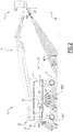
- the nacelle 1 comprises a rolling frame 2, a turret 3, a telescopic arm 4 and a platform 5.
- the frame 2 and the turret 3 constitute the lower part of the nacelle 1, while the telescopic arm 4 constitutes the lifting structure. of the nacelle 1.
- the nacelle 1 has a front side 11, a rear side 12, a left side 13 and a right side 14.
- the nacelle 1 is designed to be piloted by an operator 10 positioned on the platform 5.
- the operator 10 is shown schematically, only at figures 7, 9 and 13 , for the sake of simplification.
- the frame 2 extends along a longitudinal axis X2.
- the frame 2 is provided with axles 6 supporting the wheels 7, allowing the nacelle 1 to translate on a ground surface S.
- the wheels 7 form ground connection members S of the nacelle 1.
- the axles 6 are telescopic and articulated in rotation on the frame 2.
- the axles 6 may have any configuration suitable for the intended application.
- the axles 6 can be straight axles, telescopic or not.
- the motorization means of the chassis 2, not shown, may include an internal combustion engine or an electric motor.
- On the frame 2 can also be mounted an electronic central management unit, a hydraulic tank, a fuel tank, and / or a set of electric batteries.
- the turret 3 is mounted on the frame 2, being mobile in rotation at 360 degrees around a vertical axis Z3.
- the turret 3 is actuated by hydraulic means, not shown.
- the turret 3 comprises a longitudinal housing 31 provided to receive the arm 4 in the rest position.
- the turret 3 also includes a side flap 32 removably covering a control panel 33.
- the telescopic arm 4 is mounted on the turret 3, being articulated in rotation about a horizontal axis Y4.
- the arm 4 comprises several elongated boxes 41, 42, 43 and 44, nested one inside the other.
- the arm 4 can be an articulated lifting arm or of any other known type.
- a parallelogram structure 45 supporting the platform 5.
- the platform 5 is designed to receive a load, in particular personnel and equipment.
- the platform 5 comprises a basket 51 and a control console 52 disposed on the front side 11 of the basket 51.
- the operator 10 of the basket 1 is positioned in the basket 51 of the platform 5 and looks towards the front side 11 of the nacelle 1.
- the basket 51 is formed by various vertical and horizontal uprights.
- the basket 51 is provided with an access door 53 located on the rear side 12.
- the nacelle 1 is also equipped with a lighting system 20, making it possible to illuminate the ground S and the environment close to the nacelle 1, less than ten meters from the wheels 7.
- a lighting system 20 is designed to illuminate essentially less than five meters from the wheels 7. In other words, at least 50% of the light intensity projected by the lighting system 20 is concentrated within five meters wheels 7.
- the lighting system 20 aims to at least partially illuminate an area between 0 and 1 meter from the edge of the wheels 7, around the nacelle 1.
- the edge of the wheels 7 designates their outer casing.
- the lighting system 20 at least partially illuminates the wheels 7.
- the system 20 makes it possible to improve the visibility of the operator 10 positioned on the platform 5 and to facilitate his maneuvers, both during an operation of loading or unloading the nacelle 1 or during an operation. a shunting operation on site.
- the system 20 allows to warn people on the ground S of the intervention in progress, or to warn them in case of emergency.
- the lighting system 20 comprises several lighting devices 21, 22 and 23, arranged on the turret 3 and the platform 5.
- two devices 21 are positioned on the front of the turret 3.
- two devices 22 are positioned on the sides and the underside of the turret 3, while a device 23 is positioned on the front and the underside of the platform 5.
- the devices 21, 22 and 23 generate light beams F21, F22 and F23 projecting markings M21, M22 and M23 on the ground S.
- the devices 21, 22 and 23 are on.
- devices 21 and 23 are on, but not devices 22.
- devices 21 and 22 are on, but not device 23.
- the devices 21, 22 and 23 are configured to illuminate the ground S and the environment close to the nacelle 1.
- the beams F21 are directed generally towards the front of the turret 3, so that when the turret 3 is in the upright position relative to frame 2, the M21 markings are located on the front side 11 of the nacelle 1.
- the beams F22 are directed generally to the sides of the turret 3, so that when the turret 3 is in the upright position with respect to the frame 2 , the M22 markings are located on the lateral sides 13 and 14 of the nacelle 1.
- the beams F23 are directed generally towards the front of the platform 5, so that when the turret 3 is in the upright position relative to the chassis 2, with mast 4 and platform 5 located in its extension on the rear side, the M23 marking is located on the rear side 12 of nacelle 1.
- the light beams F21, F22 and F23 are inclined with respect to the ground S at angles ⁇ 1, ⁇ 2 and ⁇ 3 between 20 and 90 degrees inclusive. More precisely, as shown in figures 2 and 3 , each device 21, 22 and 23 generates light beams F21, F22 and F23 inclined with respect to the ground S according to a set of angles ⁇ 1, ⁇ 2 and ⁇ 3 between 20 and 90 degrees inclusive, regardless of the direction considered.
- the angles ⁇ 1 are between 50 and 75 degrees
- the angles ⁇ 2 are between 50 and 65 degrees
- the angles ⁇ 3 are between 25 and 35 degrees.
- the beams F21, F22 and F23 are oriented to illuminate less than five meters from the frame 2. More precisely, the beams F21, F22 and F23 are oriented to at least partially illuminate the area between 0 and 1 meter from the edge of the wheels 7. As shown in figures 2 and 3 , the markings M21, M22 and M23 on the ground S partially cover this area, but not entirely. Preferably to facilitate maneuvers, the markings M21, M22 and M23 extend partly below and around the wheels 7.
- the beams projected by the driving headlights fitted to motor vehicles are provided to illuminate, in dipped beam headlamps, at least thirty meters from the chassis.
- these driving lights are generally inclined relative to the ground S, in dipped beam headlights, at angles of between 3 and 15 degrees inclusive. The driving lights do not illuminate the ground S near the wheels.
- the devices 21, 22 and 23 are fixed, in other words the orientation of the beams F21, F22 and F23 is fixed.
- the devices 21, 22 and 23 can be configured to be able to orient their beams F21, F22 and F23.
- the devices 21, 22 and 23 can project orientable beams F21, F22 and F23.
- the angles ⁇ 1, ⁇ 2 and ⁇ 3 are adjustable.
- the markings M21, M22 and M23 are projected by the lighting system 20 all around the nacelle 1.
- the markings M21, M22 and M23 delimit a marked zone Z20 around the nacelle 1, materialized by a fictitious barrier B20 shown in broken lines on the figure 3 .
- the invention thus makes it possible to improve the safety of people close to the nacelle 1.
- the lighting devices 21, 22 and 23 comprise a partial shuttering system, such as a mask having a distinctive shape.
- the masks allow distinctive shapes to appear on the S floor in the M21, M22 and M23 markings.
- the distinctive shape can be a symbol, logo or text.
- the distinctive shape may in particular represent an M24 danger graphic, as shown on the example of figure 3 .
- the mask can be fixed, or designed to be removable depending on the situation. According to one variant, only certain devices 21, 22 or 23 are equipped with a mask.
- the lighting system 20 can be configured so that when starting the nacelle 1, at least some of the devices 21, 22 and 23 are automatically switched on. In service, each of the devices 21, 22 and 23 can be selectively turned on or off, at the choice of the operator 10.
- the lighting system 20 can also include a safety device provided to automatically turn on all or part of the control devices. lighting 21, 22 and 23 in case of emergency.
- the devices 21, 22 and 23 can be configured to project dynamic signals, in the form of specific light illuminations, such as as color changes or intermittent flashes of light.
- dynamic signals can be activated in an emergency, or according to the movements of the nacelle 1 or of its constituent elements, for example during the translation of the frame 2 or the descent of the platform 5.
- These signals dynamics make the lighting system 20 even more visible, which further improves the safety of persons close to the nacelle 1, as well as the safety of the operator, in particular in an emergency situation.
- the devices 21, 22 and 23 can be in the form of conventional headlights, as is the case with the devices 21 in the figures. In this case, however, these headlights do not fulfill a function of conventional driving lights.
- the devices 21, 22 and 23 may each be in the form of a box including a casing, a window, as well as one or more bulbs or light-emitting diodes (LEDs) arranged in the casing and projecting light beams at through the glass.
- LEDs light-emitting diodes
- the bulbs or diodes can be arranged according to a particular pattern.
- the lighting system 20 has a particular visual signature, reinforcing the visual identity of the nacelle 1.
- the nacelle 1 can include other auxiliary lighting devices, for example to illuminate the intervention zone at height of the operator 10.
- the devices 21, 22 or 23 can be configured to be able to orient their beams F21 , F22 and F23 in order to illuminate the intervention zone at height.
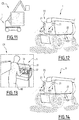
- FIG. 7 to 14 are illustrated various conditions C1, C2, C3 and C4 for the operation of the nacelle 1, in particular emergency situations.
- the figures 7, 9 , 11 and 13 are schematic representations of different work or emergency situations.
- the figures 8, 10 , 12 and 14 are partial schematic representations of the nacelle 1 shown in figure 6 , corresponding respectively to the situations of figures 7, 9 , 11 and 13 , with FC1, FC2, FC3 and FC4 light beams of different colors.
- the operator 10 is positioned in the basket 51 of the nacelle 1, in a work situation or condition C1.
- the devices 21 and 22 project green FC1 beams.
- the hand of the operator 10 is about to press an emergency stop button 54 fitted to the control console 52.
- the safety stop mode of the platform 1 is then activated, which corresponds to the condition C2.
- devices 21 and 22 project FC2 beams of red color.
- the safety stop mode can also be activated by other platform safety devices, in particular a load limiter in the platform or a tilt limiter of the chassis. These safety devices are conventional and will therefore not be described further.
- the nacelle 1 is shown in a fault situation, or condition C3.
- the devices 21 and 22 project FC3 beams of orange color.
- the operator 10 is positioned in the basket 51 of the nacelle 1, when an accident occurs. In this case, the operator 10 working at height in the basket 51 accidentally hits a beam while moving the platform 5.
- a safety system for example a removable bar 55 arranged between the operator 10 and the control console 52 then makes it possible to activate an accident mode for the nacelle 1, or condition C4.
- the devices 21 and 22 project FC4 beams of blue color.
- At least one of the lighting devices 21, 22 and 23 is configured to generate colored light beams FC1, FC2, FC3, FC4, the color of which depends on the operating conditions.
- at least some of the devices 21, 22 and 23, or even all of the devices devices 21, 22 and 23, are configured to generate colored light beams FC1, FC2, FC3 and FC4.
- the devices 21, 22 or 23 preferably comprise a set of diodes of different colors. Different colors can be projected by the same device 21, 22 or 23, with a different color for each operating condition C1, C2, C3, C4 of the gondola 1. All of the devices 21, 22 and 23 project a given color for a particular operating condition C1, C2, C3, C4 of nacelle 1.
- FIG 15 On the figure 15 is shown a lifting platform 1 according to a second embodiment of the invention.
- the constituent elements similar to the first embodiment bear the same reference numerals.
- the device 23 is positioned on the underside of the lifting structure 4, more precisely under the box 41, instead of being positioned on the platform 5.
- the device 23 can be positioned in another location of the structure. elevator 4.
- the lifting platform 1 can be shaped differently from figures 1 to 15 without departing from the scope of the invention.
- the lighting system 20 can have any configuration suitable for the intended application.
- the ground connection members S fitted to the rolling frame 2 can be caterpillars instead of wheels 7.
- the lifting platform 1 can be an articulated arm platform, a telescopic arm platform, a vertical mast platform, a scissor lift.
- the nacelle 1 can be used for maintenance or pruning work, for inventory in warehouses, for shipyards, for demolition, for construction or for maintenance and finishing of works. art, etc.
- the nacelle 1 comprises a lower part 2 + 3 equipped with members 7 for connecting to the ground S, a lifting structure 4, a platform 5 and a lighting system 20 comprising at least one lighting device 21, 22 and / or 23 arranged on the lower part 2 + 3 or on the platform 5, other than a driving light.
- This lighting device 21, 22 or 23 selectively generates colored light beams FC1, FC2, FC3 or FC4, the color of which is selected from at least two distinct colors, depending on the operating conditions C1, C2, C3 or C4 of the aerial work platform 1 including at least one safety stop situation C2 and one accident situation at height C4 of aerial work platform 1.
- the lifting platform 1 can be adapted in terms of cost, functionality and performance.
Landscapes
- Engineering & Computer Science (AREA)
- Mechanical Engineering (AREA)
- Structural Engineering (AREA)
- Life Sciences & Earth Sciences (AREA)
- Geology (AREA)
- Forklifts And Lifting Vehicles (AREA)
- Lighting Device Outwards From Vehicle And Optical Signal (AREA)
- Types And Forms Of Lifts (AREA)
- Wind Motors (AREA)
- Non-Portable Lighting Devices Or Systems Thereof (AREA)
Claims (11)
- Hubarbeitsbühne (1), umfassend:- einen unteren Teil (2, 3), der mit Mitteln (7) für die Verbindung mit dem Erdboden (S) versehen ist;- eine Hebestruktur (4);- eine von der Hebestruktur (4) getragene Plattform (5); und- ein Beleuchtungssystem (20), das wenigstens eine Beleuchtungsvorrichtung (21, 22, 23) umfasst, die auf dem unteren Teil (2, 3) oder auf der Plattform (5) vorgesehen ist und eine andere ist als ein Fahrscheinwerfer;dadurch gekennzeichnet, dass die Beleuchtungsvorrichtung (21, 22, 23) selektiv farbige Lichtstrahlen (FC1, FC2, FC3, FC4) erzeugt, deren Farbe ausgewählt ist aus wenigstens zwei verschiedenen Farben, die jeweils entsprechen:- einer Situation einer Sicherheitsabschaltung (C2) der Hubarbeitsbühne (1);- einer Situation eines Höhenunfalls (C4) der Hubarbeitsbühne (1).
- Hubarbeitsbühne (1) nach Anspruch 1, dadurch gekennzeichnet, dass die Beleuchtungsvorrichtung (21, 22, 23) selektiv erzeugt:- einen roten Lichtstrahl (FC2) in der Situation einer Sicherheitsabschaltung (C2);- einen blauen Lichtstrahl (FC4) in der Situation eines Höhenunfalls (C4).
- Hubarbeitsbühne (1) nach einem der Ansprüche 1 und 2, dadurch gekennzeichnet, dass die Beleuchtungsvorrichtung (21, 22, 23) ferner selektiv erzeugt:- einen grünen Lichtstrahl (FC1) in der Situation eines Betriebs (C1);- einen orangen Lichtstrahl (FC3) in der Situation eines Betriebsausfalls (C3).
- Hubarbeitsbühne (1) nach einem der vorhergehenden Ansprüche, dadurch gekennzeichnet, dass
die Beleuchtungsvorrichtung (21, 22, 23) selektiv farbige Lichtstrahlen (FC1, FC2, FC3, FC4) erzeugt, die zum Erdboden (S) und zur näheren Umgebung der Hubarbeitsbühne (1) hin weisen, die wenigstens zum Teil eine Zone zwischen 0 und 1 m vom Rand der Mittel (7) für die Verbindung mit dem Erdboden (S) einschließt. - Hubarbeitsbühne (1) nach einem der vorhergehenden Ansprüche, dadurch gekennzeichnet, dass die farbigen Lichtstrahlen (FC1, FC2, FC3, FC4) Markierungen (M21, M22; M21, M22, M23) auf den Erdboden (S) projizieren, die eine gekennzeichnete Zone (Z20) um die Hubarbeitsbühne (1) herum begrenzen.
- Hubarbeitsbühne (1) nach Anspruch 5, dadurch gekennzeichnet, dass wenigstens eine der Markierungen (M21, M22; M21, M22, M23) auf dem Erdboden (S) eine figürliche Form (M24) aufweist, zum Beispiel eine Gefahrengrafik.
- Hubarbeitsbühne (1) nach einem der vorhergehenden Ansprüche, dadurch gekennzeichnet, dass die Beleuchtungsvorrichtung (21, 22, 23) selektiv farbige Lichtstrahlen (FC1, FC2, FC3, FC4) erzeugt, die zum Erdboden (S) und zur näheren Umgebung der Hubarbeitsbühne (1) hin weisen, in wenigstens zehn Meter von den Mitteln (7) für die Verbindung mit dem Erdboden (S).
- Hubarbeitsbühne (1) nach einem der vorhergehenden Ansprüche, dadurch gekennzeichnet, dass die Beleuchtungsvorrichtung (21, 22, 23) wenigstens teilweise die Mittel (7) für die Verbindung mit dem Erdboden (S) beleuchtet.
- Hubarbeitsbühne (1) nach einem der vorhergehenden Ansprüche, dadurch gekennzeichnet, dass das Beleuchtungssystem (20) verschiedene Beleuchtungsvorrichtungen (21, 22, 23) umfasst, die auf dem unteren Teil (2, 3), auf der Hebestruktur (4) und/oder auf der Plattform (5) vorgesehen sind, wobei jede selektiv farbige Lichtstrahlen (FC1, FC2, FC3, FC4) erzeugt, deren Farbe von den Betriebsbedingungen (C1, C2, C3, C4) der Hubarbeitsbühne (1) abhängt.
- Hubarbeitsbühne (1) nach Anspruch 9, dadurch gekennzeichnet, dass das Beleuchtungssystem (20) umfasst:- wenigstens eine Beleuchtungsvorrichtung (21), die auf einer vorderen Fläche (11) des unteren Teils (2, 3) vorgesehen ist, insbesondere auf einer vorderen Seite (11) eines Turms (3), der dem unteren Teil (2, 3) zugehörig ist;- wenigstens zwei Beleuchtungsvorrichtungen (22), die auf den seitlichen Flächen (13; 14) des unteren Teils (2, 3) vorgesehen sind, insbesondere auf einer seitlichen Fläche (13; 14) und der Unterseite eines Turms (3), der dem unteren Teil (2, 3) zugehörig ist; und- wenigstens eine Beleuchtungsvorrichtung (23) die auf der Hebestruktur (4) oder auf der Plattform (5) vorgesehen ist.
- Verfahren für die Verwendung einer Hubarbeitsbühne (1) nach einem der Ansprüche 1 bis 10, dadurch gekennzeichnet, dass bei einer vorher bestimmten Änderung der Betriebsbedingungen (C1, C2, C3, C4) der Hubarbeitsbühne (1), insbesondere bei einem Übergang in die Situation eines Betriebs (C1), in die Situation einer Sicherheitsabschaltung (C2), in die Situation eines Betriebsausfalls (C3) oder in die Situation eines Höhenunfalls (C4),
die Beleuchtungsvorrichtung (21, 22, 23) selektiv farbige Lichtstrahlen (FC1, FC2, FC3, FC4) mit einer vorher bestimmten Farbe erzeugt.
Applications Claiming Priority (2)
| Application Number | Priority Date | Filing Date | Title |
|---|---|---|---|
| FR1462823A FR3030472B1 (fr) | 2014-12-18 | 2014-12-18 | Nacelle elevatrice et procede de mise en oeuvre |
| PCT/EP2015/080212 WO2016097139A1 (fr) | 2014-12-18 | 2015-12-17 | Nacelle élévatrice et procédé de mise en oeuvre |
Publications (2)
| Publication Number | Publication Date |
|---|---|
| EP3233714A1 EP3233714A1 (de) | 2017-10-25 |
| EP3233714B1 true EP3233714B1 (de) | 2021-10-20 |
Family
ID=52477983
Family Applications (1)
| Application Number | Title | Priority Date | Filing Date |
|---|---|---|---|
| EP15820472.7A Active EP3233714B1 (de) | 2014-12-18 | 2015-12-17 | Luftaufzug und verfahren zur implementierung davon |
Country Status (7)
| Country | Link |
|---|---|
| US (1) | US10710857B2 (de) |
| EP (1) | EP3233714B1 (de) |
| CN (1) | CN107107808B (de) |
| AU (1) | AU2015367391B2 (de) |
| CA (1) | CA2969951C (de) |
| FR (1) | FR3030472B1 (de) |
| WO (1) | WO2016097139A1 (de) |
Families Citing this family (10)
| Publication number | Priority date | Publication date | Assignee | Title |
|---|---|---|---|---|
| JP2019027166A (ja) * | 2017-07-31 | 2019-02-21 | 本田技研工業株式会社 | 作業機 |
| JP6606133B2 (ja) * | 2017-07-31 | 2019-11-13 | 本田技研工業株式会社 | 除雪機 |
| AT520489A1 (de) * | 2017-10-11 | 2019-04-15 | Rosenbauer Int Ag | Verfahren zur Umfeldbeleuchtung eines Einsatzfahrzeugs |
| JP7374560B2 (ja) * | 2019-12-24 | 2023-11-07 | 株式会社アイチコーポレーション | 高所作業車の走行案内装置 |
| CA3163140A1 (en) | 2020-02-21 | 2021-08-26 | Sebastian Theos | Modify vehicle parameter based on vehicle position information |
| USD981075S1 (en) * | 2020-05-22 | 2023-03-14 | Jiangsu Xcmg Construction Machinery Research Institute Ltd. | Aerial platform truck |
| CN112209313A (zh) * | 2020-10-13 | 2021-01-12 | 国网江苏省电力有限公司徐州供电分公司 | 一种自行走式快速跨越吊装一体机的跨越支撑作业方法 |
| US11807997B2 (en) | 2021-05-12 | 2023-11-07 | Caterpillar Paving Products Inc. | Systems and methods of visual guidance |
| US20230399215A1 (en) * | 2022-06-14 | 2023-12-14 | Microsoft Technology Licensing, Llc | Lift with swiveling and horizontally sliding platform |
| FR3138077A1 (fr) * | 2022-07-22 | 2024-01-26 | Manitou Bf | Engin de manutention de charge et/ou de personne |
Family Cites Families (21)
| Publication number | Priority date | Publication date | Assignee | Title |
|---|---|---|---|---|
| DE2924820C2 (de) * | 1979-06-20 | 1983-01-20 | Carl Metz Gmbh, 7500 Karlsruhe | Fahrbares Arbeits- und/oder Rettungsgerät |
| US4456093A (en) * | 1981-06-16 | 1984-06-26 | Interstate Electronics Corp. | Control system for aerial work platform machine and method of controlling an aerial work platform machine |
| US6272413B1 (en) * | 1999-03-19 | 2001-08-07 | Kabushiki Kaisha Aichi Corporation | Safety system for boom-equipped vehicle |
| US6208260B1 (en) * | 1999-11-02 | 2001-03-27 | Jill West | Personal warning method and apparatus for traveling loads |
| US6784800B2 (en) * | 2001-06-19 | 2004-08-31 | Signal Tech | Industrial vehicle safety system |
| FR2836468B1 (fr) * | 2002-02-28 | 2004-10-01 | Pinguely Haulotte | Nacelle elevatrice a securite amelioree |
| FR2851763B1 (fr) * | 2003-02-27 | 2006-03-17 | Pinguely Haulotte | Nacelle elevatrice a ciseaux et procede de controle de l'elevation et de l'abaissement de la plate-forme d'une telle nacelle |
| GB2472441B (en) * | 2009-08-07 | 2013-02-13 | Niftylift Ltd | Control system,preferably for enhanced operator safety |
| US9336660B2 (en) * | 2010-03-11 | 2016-05-10 | David McIntosh | Overhead hazard warning systems |
| FR2958579B1 (fr) * | 2010-04-09 | 2012-04-20 | Haulotte Group | Systeme d'essieu, module d'essieu comprenant au moins un tel systeme d'essieu et vehicule comprenant au moins un tel module |
| US9230419B2 (en) * | 2010-07-27 | 2016-01-05 | Rite-Hite Holding Corporation | Methods and apparatus to detect and warn proximate entities of interest |
| US9030332B2 (en) * | 2011-06-27 | 2015-05-12 | Motion Metrics International Corp. | Method and apparatus for generating an indication of an object within an operating ambit of heavy loading equipment |
| US20130209109A1 (en) * | 2012-02-10 | 2013-08-15 | Joseph Georgiano | Fiber Optic Intercom for Bucket Truck Application |
| DE102012024494A1 (de) * | 2012-12-14 | 2014-06-18 | Audi Ag | Flurförderzeug mit einer optischen Warneinrichtung, Kraftfahrzeug mit einer optischen Warneinrichtung und Projektor zur Verwendung als optische Warneinrichtung |
| US9583003B2 (en) * | 2013-05-31 | 2017-02-28 | Hitachi Automotive Systems, Ltd. | Vehicle danger notification control apparatus |
| US9957121B2 (en) * | 2013-08-13 | 2018-05-01 | Rite-Hite Holding Corporation | Safety systems for vertically storing dock levelers |
| US9865170B2 (en) * | 2013-08-14 | 2018-01-09 | Conduent Business Services, Llc | System and method to increase conspicuousness of vehicles |
| CN203713680U (zh) * | 2014-02-26 | 2014-07-16 | 安徽合力股份有限公司 | 一种设有安全警示装置的工业车辆 |
| US9926148B2 (en) * | 2014-06-27 | 2018-03-27 | Rite-Hite Holding Corporation | Pedestrian-vehicle safety systems for loading docks |
| FR3030471B1 (fr) * | 2014-12-18 | 2019-06-14 | Haulotte Group | Nacelle elevatrice et procede de mise en oeuvre |
| GB2553137B (en) * | 2016-08-25 | 2019-11-20 | Bluesky Solutions Ltd | Anti-entrapment device for scissor lifts |
-
2014
- 2014-12-18 FR FR1462823A patent/FR3030472B1/fr not_active Expired - Fee Related
-
2015
- 2015-12-17 US US15/534,661 patent/US10710857B2/en active Active
- 2015-12-17 AU AU2015367391A patent/AU2015367391B2/en active Active
- 2015-12-17 CA CA2969951A patent/CA2969951C/fr active Active
- 2015-12-17 CN CN201580068977.XA patent/CN107107808B/zh active Active
- 2015-12-17 EP EP15820472.7A patent/EP3233714B1/de active Active
- 2015-12-17 WO PCT/EP2015/080212 patent/WO2016097139A1/fr active Application Filing
Also Published As
| Publication number | Publication date |
|---|---|
| AU2015367391B2 (en) | 2019-11-21 |
| FR3030472B1 (fr) | 2020-10-16 |
| CA2969951A1 (fr) | 2016-06-23 |
| EP3233714A1 (de) | 2017-10-25 |
| CN107107808A (zh) | 2017-08-29 |
| US20180265340A1 (en) | 2018-09-20 |
| FR3030472A1 (fr) | 2016-06-24 |
| US10710857B2 (en) | 2020-07-14 |
| CN107107808B (zh) | 2019-12-13 |
| WO2016097139A1 (fr) | 2016-06-23 |
| AU2015367391A1 (en) | 2017-07-06 |
| CA2969951C (fr) | 2023-02-28 |
Similar Documents
| Publication | Publication Date | Title |
|---|---|---|
| EP3233714B1 (de) | Luftaufzug und verfahren zur implementierung davon | |
| EP3233713B1 (de) | Luftaufzug und verfahren zur implementierung davon | |
| EP3390266B1 (de) | Hubarbeitsbühne | |
| EP3515854B1 (de) | Visuelle hilfe für bodenbewegung einer hebebühne | |
| EP3387498B1 (de) | Steuerkonsole und luftseilbahn mit solch einer steuerkonsole | |
| FR3018052A1 (fr) | Machine de travail, notamment camion a benne | |
| FR3091329A1 (fr) | Système de feu de gabarit | |
| EP2810825B1 (de) | Vorrichtung zum Rückwärtssehen für ein Kraftfahrzeug | |
| EP3755843B1 (de) | Verkehrsbeschilderungssystem an einem baustellenfahrzeug | |
| EP2426036B1 (de) | Kraftfahrzeug für die Überwachung von Gelände, Gegenstände oder Menschen | |
| EP1520832A1 (de) | Ein Fahrzeug zum Heben eines Persons und seines Arbeitskorbes | |
| FR2675494A1 (fr) | Dispositif de commande d'une nacelle pivotante montee sur un engin de levage. |
Legal Events
| Date | Code | Title | Description |
|---|---|---|---|
| STAA | Information on the status of an ep patent application or granted ep patent |
Free format text: STATUS: THE INTERNATIONAL PUBLICATION HAS BEEN MADE |
|
| PUAI | Public reference made under article 153(3) epc to a published international application that has entered the european phase |
Free format text: ORIGINAL CODE: 0009012 |
|
| STAA | Information on the status of an ep patent application or granted ep patent |
Free format text: STATUS: REQUEST FOR EXAMINATION WAS MADE |
|
| 17P | Request for examination filed |
Effective date: 20170710 |
|
| AK | Designated contracting states |
Kind code of ref document: A1 Designated state(s): AL AT BE BG CH CY CZ DE DK EE ES FI FR GB GR HR HU IE IS IT LI LT LU LV MC MK MT NL NO PL PT RO RS SE SI SK SM TR |
|
| AX | Request for extension of the european patent |
Extension state: BA ME |
|
| DAV | Request for validation of the european patent (deleted) | ||
| DAX | Request for extension of the european patent (deleted) | ||
| RAP1 | Party data changed (applicant data changed or rights of an application transferred) |
Owner name: HAULOTTE GROUP |
|
| GRAP | Despatch of communication of intention to grant a patent |
Free format text: ORIGINAL CODE: EPIDOSNIGR1 |
|
| STAA | Information on the status of an ep patent application or granted ep patent |
Free format text: STATUS: GRANT OF PATENT IS INTENDED |
|
| INTG | Intention to grant announced |
Effective date: 20210609 |
|
| GRAS | Grant fee paid |
Free format text: ORIGINAL CODE: EPIDOSNIGR3 |
|
| GRAA | (expected) grant |
Free format text: ORIGINAL CODE: 0009210 |
|
| STAA | Information on the status of an ep patent application or granted ep patent |
Free format text: STATUS: THE PATENT HAS BEEN GRANTED |
|
| AK | Designated contracting states |
Kind code of ref document: B1 Designated state(s): AL AT BE BG CH CY CZ DE DK EE ES FI FR GB GR HR HU IE IS IT LI LT LU LV MC MK MT NL NO PL PT RO RS SE SI SK SM TR |
|
| REG | Reference to a national code |
Ref country code: GB Ref legal event code: FG4D Free format text: NOT ENGLISH |
|
| REG | Reference to a national code |
Ref country code: CH Ref legal event code: EP |
|
| REG | Reference to a national code |
Ref country code: IE Ref legal event code: FG4D Free format text: LANGUAGE OF EP DOCUMENT: FRENCH |
|
| REG | Reference to a national code |
Ref country code: DE Ref legal event code: R096 Ref document number: 602015074325 Country of ref document: DE |
|
| REG | Reference to a national code |
Ref country code: AT Ref legal event code: REF Ref document number: 1439801 Country of ref document: AT Kind code of ref document: T Effective date: 20211115 |
|
| REG | Reference to a national code |
Ref country code: LT Ref legal event code: MG9D |
|
| REG | Reference to a national code |
Ref country code: NL Ref legal event code: MP Effective date: 20211020 |
|
| REG | Reference to a national code |
Ref country code: AT Ref legal event code: MK05 Ref document number: 1439801 Country of ref document: AT Kind code of ref document: T Effective date: 20211020 |
|
| PG25 | Lapsed in a contracting state [announced via postgrant information from national office to epo] |
Ref country code: RS Free format text: LAPSE BECAUSE OF FAILURE TO SUBMIT A TRANSLATION OF THE DESCRIPTION OR TO PAY THE FEE WITHIN THE PRESCRIBED TIME-LIMIT Effective date: 20211020 Ref country code: LT Free format text: LAPSE BECAUSE OF FAILURE TO SUBMIT A TRANSLATION OF THE DESCRIPTION OR TO PAY THE FEE WITHIN THE PRESCRIBED TIME-LIMIT Effective date: 20211020 Ref country code: FI Free format text: LAPSE BECAUSE OF FAILURE TO SUBMIT A TRANSLATION OF THE DESCRIPTION OR TO PAY THE FEE WITHIN THE PRESCRIBED TIME-LIMIT Effective date: 20211020 Ref country code: BG Free format text: LAPSE BECAUSE OF FAILURE TO SUBMIT A TRANSLATION OF THE DESCRIPTION OR TO PAY THE FEE WITHIN THE PRESCRIBED TIME-LIMIT Effective date: 20220120 Ref country code: AT Free format text: LAPSE BECAUSE OF FAILURE TO SUBMIT A TRANSLATION OF THE DESCRIPTION OR TO PAY THE FEE WITHIN THE PRESCRIBED TIME-LIMIT Effective date: 20211020 |
|
| PG25 | Lapsed in a contracting state [announced via postgrant information from national office to epo] |
Ref country code: IS Free format text: LAPSE BECAUSE OF FAILURE TO SUBMIT A TRANSLATION OF THE DESCRIPTION OR TO PAY THE FEE WITHIN THE PRESCRIBED TIME-LIMIT Effective date: 20220220 Ref country code: SE Free format text: LAPSE BECAUSE OF FAILURE TO SUBMIT A TRANSLATION OF THE DESCRIPTION OR TO PAY THE FEE WITHIN THE PRESCRIBED TIME-LIMIT Effective date: 20211020 Ref country code: PT Free format text: LAPSE BECAUSE OF FAILURE TO SUBMIT A TRANSLATION OF THE DESCRIPTION OR TO PAY THE FEE WITHIN THE PRESCRIBED TIME-LIMIT Effective date: 20220221 Ref country code: PL Free format text: LAPSE BECAUSE OF FAILURE TO SUBMIT A TRANSLATION OF THE DESCRIPTION OR TO PAY THE FEE WITHIN THE PRESCRIBED TIME-LIMIT Effective date: 20211020 Ref country code: NO Free format text: LAPSE BECAUSE OF FAILURE TO SUBMIT A TRANSLATION OF THE DESCRIPTION OR TO PAY THE FEE WITHIN THE PRESCRIBED TIME-LIMIT Effective date: 20220120 Ref country code: NL Free format text: LAPSE BECAUSE OF FAILURE TO SUBMIT A TRANSLATION OF THE DESCRIPTION OR TO PAY THE FEE WITHIN THE PRESCRIBED TIME-LIMIT Effective date: 20211020 Ref country code: LV Free format text: LAPSE BECAUSE OF FAILURE TO SUBMIT A TRANSLATION OF THE DESCRIPTION OR TO PAY THE FEE WITHIN THE PRESCRIBED TIME-LIMIT Effective date: 20211020 Ref country code: HR Free format text: LAPSE BECAUSE OF FAILURE TO SUBMIT A TRANSLATION OF THE DESCRIPTION OR TO PAY THE FEE WITHIN THE PRESCRIBED TIME-LIMIT Effective date: 20211020 Ref country code: GR Free format text: LAPSE BECAUSE OF FAILURE TO SUBMIT A TRANSLATION OF THE DESCRIPTION OR TO PAY THE FEE WITHIN THE PRESCRIBED TIME-LIMIT Effective date: 20220121 Ref country code: ES Free format text: LAPSE BECAUSE OF FAILURE TO SUBMIT A TRANSLATION OF THE DESCRIPTION OR TO PAY THE FEE WITHIN THE PRESCRIBED TIME-LIMIT Effective date: 20211020 |
|
| REG | Reference to a national code |
Ref country code: DE Ref legal event code: R097 Ref document number: 602015074325 Country of ref document: DE |
|
| PG25 | Lapsed in a contracting state [announced via postgrant information from national office to epo] |
Ref country code: SM Free format text: LAPSE BECAUSE OF FAILURE TO SUBMIT A TRANSLATION OF THE DESCRIPTION OR TO PAY THE FEE WITHIN THE PRESCRIBED TIME-LIMIT Effective date: 20211020 Ref country code: SK Free format text: LAPSE BECAUSE OF FAILURE TO SUBMIT A TRANSLATION OF THE DESCRIPTION OR TO PAY THE FEE WITHIN THE PRESCRIBED TIME-LIMIT Effective date: 20211020 Ref country code: RO Free format text: LAPSE BECAUSE OF FAILURE TO SUBMIT A TRANSLATION OF THE DESCRIPTION OR TO PAY THE FEE WITHIN THE PRESCRIBED TIME-LIMIT Effective date: 20211020 Ref country code: MC Free format text: LAPSE BECAUSE OF FAILURE TO SUBMIT A TRANSLATION OF THE DESCRIPTION OR TO PAY THE FEE WITHIN THE PRESCRIBED TIME-LIMIT Effective date: 20211020 Ref country code: EE Free format text: LAPSE BECAUSE OF FAILURE TO SUBMIT A TRANSLATION OF THE DESCRIPTION OR TO PAY THE FEE WITHIN THE PRESCRIBED TIME-LIMIT Effective date: 20211020 Ref country code: DK Free format text: LAPSE BECAUSE OF FAILURE TO SUBMIT A TRANSLATION OF THE DESCRIPTION OR TO PAY THE FEE WITHIN THE PRESCRIBED TIME-LIMIT Effective date: 20211020 Ref country code: CZ Free format text: LAPSE BECAUSE OF FAILURE TO SUBMIT A TRANSLATION OF THE DESCRIPTION OR TO PAY THE FEE WITHIN THE PRESCRIBED TIME-LIMIT Effective date: 20211020 |
|
| REG | Reference to a national code |
Ref country code: CH Ref legal event code: PL |
|
| PLBE | No opposition filed within time limit |
Free format text: ORIGINAL CODE: 0009261 |
|
| STAA | Information on the status of an ep patent application or granted ep patent |
Free format text: STATUS: NO OPPOSITION FILED WITHIN TIME LIMIT |
|
| REG | Reference to a national code |
Ref country code: BE Ref legal event code: MM Effective date: 20211231 |
|
| 26N | No opposition filed |
Effective date: 20220721 |
|
| PG25 | Lapsed in a contracting state [announced via postgrant information from national office to epo] |
Ref country code: LU Free format text: LAPSE BECAUSE OF NON-PAYMENT OF DUE FEES Effective date: 20211217 Ref country code: IE Free format text: LAPSE BECAUSE OF NON-PAYMENT OF DUE FEES Effective date: 20211217 Ref country code: AL Free format text: LAPSE BECAUSE OF FAILURE TO SUBMIT A TRANSLATION OF THE DESCRIPTION OR TO PAY THE FEE WITHIN THE PRESCRIBED TIME-LIMIT Effective date: 20211020 |
|
| PG25 | Lapsed in a contracting state [announced via postgrant information from national office to epo] |
Ref country code: SI Free format text: LAPSE BECAUSE OF FAILURE TO SUBMIT A TRANSLATION OF THE DESCRIPTION OR TO PAY THE FEE WITHIN THE PRESCRIBED TIME-LIMIT Effective date: 20211020 Ref country code: BE Free format text: LAPSE BECAUSE OF NON-PAYMENT OF DUE FEES Effective date: 20211231 |
|
| PG25 | Lapsed in a contracting state [announced via postgrant information from national office to epo] |
Ref country code: LI Free format text: LAPSE BECAUSE OF NON-PAYMENT OF DUE FEES Effective date: 20211231 Ref country code: CH Free format text: LAPSE BECAUSE OF NON-PAYMENT OF DUE FEES Effective date: 20211231 |
|
| PG25 | Lapsed in a contracting state [announced via postgrant information from national office to epo] |
Ref country code: HU Free format text: LAPSE BECAUSE OF FAILURE TO SUBMIT A TRANSLATION OF THE DESCRIPTION OR TO PAY THE FEE WITHIN THE PRESCRIBED TIME-LIMIT; INVALID AB INITIO Effective date: 20151217 |
|
| P01 | Opt-out of the competence of the unified patent court (upc) registered |
Effective date: 20230502 |
|
| PG25 | Lapsed in a contracting state [announced via postgrant information from national office to epo] |
Ref country code: CY Free format text: LAPSE BECAUSE OF FAILURE TO SUBMIT A TRANSLATION OF THE DESCRIPTION OR TO PAY THE FEE WITHIN THE PRESCRIBED TIME-LIMIT Effective date: 20211020 |
|
| PGFP | Annual fee paid to national office [announced via postgrant information from national office to epo] |
Ref country code: GB Payment date: 20231221 Year of fee payment: 9 |
|
| PGFP | Annual fee paid to national office [announced via postgrant information from national office to epo] |
Ref country code: TR Payment date: 20231206 Year of fee payment: 9 Ref country code: IT Payment date: 20231211 Year of fee payment: 9 Ref country code: FR Payment date: 20231109 Year of fee payment: 9 Ref country code: DE Payment date: 20231208 Year of fee payment: 9 |
|
| PG25 | Lapsed in a contracting state [announced via postgrant information from national office to epo] |
Ref country code: MK Free format text: LAPSE BECAUSE OF FAILURE TO SUBMIT A TRANSLATION OF THE DESCRIPTION OR TO PAY THE FEE WITHIN THE PRESCRIBED TIME-LIMIT Effective date: 20211020 |