EP3233014B1 - Mechanische einheit zur kraft/momenteinstellung mit einem einzelpunkt - Google Patents
Mechanische einheit zur kraft/momenteinstellung mit einem einzelpunkt Download PDFInfo
- Publication number
- EP3233014B1 EP3233014B1 EP15869448.9A EP15869448A EP3233014B1 EP 3233014 B1 EP3233014 B1 EP 3233014B1 EP 15869448 A EP15869448 A EP 15869448A EP 3233014 B1 EP3233014 B1 EP 3233014B1
- Authority
- EP
- European Patent Office
- Prior art keywords
- load
- torque
- single point
- adjusting
- mechanical assembly
- Prior art date
- Legal status (The legal status is an assumption and is not a legal conclusion. Google has not performed a legal analysis and makes no representation as to the accuracy of the status listed.)
- Active
Links
Images


Classifications
-
- A—HUMAN NECESSITIES
- A61—MEDICAL OR VETERINARY SCIENCE; HYGIENE
- A61H—PHYSICAL THERAPY APPARATUS, e.g. DEVICES FOR LOCATING OR STIMULATING REFLEX POINTS IN THE BODY; ARTIFICIAL RESPIRATION; MASSAGE; BATHING DEVICES FOR SPECIAL THERAPEUTIC OR HYGIENIC PURPOSES OR SPECIFIC PARTS OF THE BODY
- A61H3/00—Appliances for aiding patients or disabled persons to walk about
-
- A—HUMAN NECESSITIES
- A61—MEDICAL OR VETERINARY SCIENCE; HYGIENE
- A61F—FILTERS IMPLANTABLE INTO BLOOD VESSELS; PROSTHESES; DEVICES PROVIDING PATENCY TO, OR PREVENTING COLLAPSING OF, TUBULAR STRUCTURES OF THE BODY, e.g. STENTS; ORTHOPAEDIC, NURSING OR CONTRACEPTIVE DEVICES; FOMENTATION; TREATMENT OR PROTECTION OF EYES OR EARS; BANDAGES, DRESSINGS OR ABSORBENT PADS; FIRST-AID KITS
- A61F5/00—Orthopaedic methods or devices for non-surgical treatment of bones or joints; Nursing devices ; Anti-rape devices
- A61F5/01—Orthopaedic devices, e.g. long-term immobilising or pressure directing devices for treating broken or deformed bones such as splints, casts or braces
- A61F5/0102—Orthopaedic devices, e.g. long-term immobilising or pressure directing devices for treating broken or deformed bones such as splints, casts or braces specially adapted for correcting deformities of the limbs or for supporting them; Ortheses, e.g. with articulations
-
- A—HUMAN NECESSITIES
- A41—WEARING APPAREL
- A41D—OUTERWEAR; PROTECTIVE GARMENTS; ACCESSORIES
- A41D1/00—Garments
- A41D1/02—Jackets
-
- A—HUMAN NECESSITIES
- A41—WEARING APPAREL
- A41F—GARMENT FASTENINGS; SUSPENDERS
- A41F9/00—Belts, girdles, or waistbands for trousers or skirts
-
- A—HUMAN NECESSITIES
- A61—MEDICAL OR VETERINARY SCIENCE; HYGIENE
- A61H—PHYSICAL THERAPY APPARATUS, e.g. DEVICES FOR LOCATING OR STIMULATING REFLEX POINTS IN THE BODY; ARTIFICIAL RESPIRATION; MASSAGE; BATHING DEVICES FOR SPECIAL THERAPEUTIC OR HYGIENIC PURPOSES OR SPECIFIC PARTS OF THE BODY
- A61H1/00—Apparatus for passive exercising; Vibrating apparatus; Chiropractic devices, e.g. body impacting devices, external devices for briefly extending or aligning unbroken bones
- A61H1/02—Stretching or bending or torsioning apparatus for exercising
- A61H1/0237—Stretching or bending or torsioning apparatus for exercising for the lower limbs
- A61H1/024—Knee
-
- A—HUMAN NECESSITIES
- A61—MEDICAL OR VETERINARY SCIENCE; HYGIENE
- A61H—PHYSICAL THERAPY APPARATUS, e.g. DEVICES FOR LOCATING OR STIMULATING REFLEX POINTS IN THE BODY; ARTIFICIAL RESPIRATION; MASSAGE; BATHING DEVICES FOR SPECIAL THERAPEUTIC OR HYGIENIC PURPOSES OR SPECIFIC PARTS OF THE BODY
- A61H1/00—Apparatus for passive exercising; Vibrating apparatus; Chiropractic devices, e.g. body impacting devices, external devices for briefly extending or aligning unbroken bones
- A61H1/02—Stretching or bending or torsioning apparatus for exercising
- A61H1/0237—Stretching or bending or torsioning apparatus for exercising for the lower limbs
- A61H1/0244—Hip
-
- B—PERFORMING OPERATIONS; TRANSPORTING
- B25—HAND TOOLS; PORTABLE POWER-DRIVEN TOOLS; MANIPULATORS
- B25J—MANIPULATORS; CHAMBERS PROVIDED WITH MANIPULATION DEVICES
- B25J9/00—Program-controlled manipulators
- B25J9/0006—Exoskeletons, i.e. resembling a human figure
-
- A—HUMAN NECESSITIES
- A61—MEDICAL OR VETERINARY SCIENCE; HYGIENE
- A61F—FILTERS IMPLANTABLE INTO BLOOD VESSELS; PROSTHESES; DEVICES PROVIDING PATENCY TO, OR PREVENTING COLLAPSING OF, TUBULAR STRUCTURES OF THE BODY, e.g. STENTS; ORTHOPAEDIC, NURSING OR CONTRACEPTIVE DEVICES; FOMENTATION; TREATMENT OR PROTECTION OF EYES OR EARS; BANDAGES, DRESSINGS OR ABSORBENT PADS; FIRST-AID KITS
- A61F5/00—Orthopaedic methods or devices for non-surgical treatment of bones or joints; Nursing devices ; Anti-rape devices
- A61F5/01—Orthopaedic devices, e.g. long-term immobilising or pressure directing devices for treating broken or deformed bones such as splints, casts or braces
- A61F5/0102—Orthopaedic devices, e.g. long-term immobilising or pressure directing devices for treating broken or deformed bones such as splints, casts or braces specially adapted for correcting deformities of the limbs or for supporting them; Ortheses, e.g. with articulations
- A61F2005/0132—Additional features of the articulation
- A61F2005/0165—Additional features of the articulation with limits of movement
- A61F2005/0167—Additional features of the articulation with limits of movement adjustable
-
- A—HUMAN NECESSITIES
- A61—MEDICAL OR VETERINARY SCIENCE; HYGIENE
- A61F—FILTERS IMPLANTABLE INTO BLOOD VESSELS; PROSTHESES; DEVICES PROVIDING PATENCY TO, OR PREVENTING COLLAPSING OF, TUBULAR STRUCTURES OF THE BODY, e.g. STENTS; ORTHOPAEDIC, NURSING OR CONTRACEPTIVE DEVICES; FOMENTATION; TREATMENT OR PROTECTION OF EYES OR EARS; BANDAGES, DRESSINGS OR ABSORBENT PADS; FIRST-AID KITS
- A61F5/00—Orthopaedic methods or devices for non-surgical treatment of bones or joints; Nursing devices ; Anti-rape devices
- A61F5/01—Orthopaedic devices, e.g. long-term immobilising or pressure directing devices for treating broken or deformed bones such as splints, casts or braces
- A61F5/0102—Orthopaedic devices, e.g. long-term immobilising or pressure directing devices for treating broken or deformed bones such as splints, casts or braces specially adapted for correcting deformities of the limbs or for supporting them; Ortheses, e.g. with articulations
- A61F2005/0132—Additional features of the articulation
- A61F2005/0179—Additional features of the articulation with spring means
-
- A—HUMAN NECESSITIES
- A61—MEDICAL OR VETERINARY SCIENCE; HYGIENE
- A61H—PHYSICAL THERAPY APPARATUS, e.g. DEVICES FOR LOCATING OR STIMULATING REFLEX POINTS IN THE BODY; ARTIFICIAL RESPIRATION; MASSAGE; BATHING DEVICES FOR SPECIAL THERAPEUTIC OR HYGIENIC PURPOSES OR SPECIFIC PARTS OF THE BODY
- A61H2201/00—Characteristics of apparatus not provided for in the preceding codes
- A61H2201/12—Driving means
- A61H2201/1253—Driving means driven by a human being, e.g. hand driven
- A61H2201/1261—Driving means driven by a human being, e.g. hand driven combined with active exercising of the patient
-
- A—HUMAN NECESSITIES
- A61—MEDICAL OR VETERINARY SCIENCE; HYGIENE
- A61H—PHYSICAL THERAPY APPARATUS, e.g. DEVICES FOR LOCATING OR STIMULATING REFLEX POINTS IN THE BODY; ARTIFICIAL RESPIRATION; MASSAGE; BATHING DEVICES FOR SPECIAL THERAPEUTIC OR HYGIENIC PURPOSES OR SPECIFIC PARTS OF THE BODY
- A61H2201/00—Characteristics of apparatus not provided for in the preceding codes
- A61H2201/16—Physical interface with patient
- A61H2201/1602—Physical interface with patient kind of interface, e.g. head rest, knee support or lumbar support
- A61H2201/1614—Shoulder, e.g. for neck stretching
- A61H2201/1616—Holding means therefor
-
- A—HUMAN NECESSITIES
- A61—MEDICAL OR VETERINARY SCIENCE; HYGIENE
- A61H—PHYSICAL THERAPY APPARATUS, e.g. DEVICES FOR LOCATING OR STIMULATING REFLEX POINTS IN THE BODY; ARTIFICIAL RESPIRATION; MASSAGE; BATHING DEVICES FOR SPECIAL THERAPEUTIC OR HYGIENIC PURPOSES OR SPECIFIC PARTS OF THE BODY
- A61H2201/00—Characteristics of apparatus not provided for in the preceding codes
- A61H2201/16—Physical interface with patient
- A61H2201/1602—Physical interface with patient kind of interface, e.g. head rest, knee support or lumbar support
- A61H2201/1628—Pelvis
- A61H2201/163—Pelvis holding means therefor
-
- A—HUMAN NECESSITIES
- A61—MEDICAL OR VETERINARY SCIENCE; HYGIENE
- A61H—PHYSICAL THERAPY APPARATUS, e.g. DEVICES FOR LOCATING OR STIMULATING REFLEX POINTS IN THE BODY; ARTIFICIAL RESPIRATION; MASSAGE; BATHING DEVICES FOR SPECIAL THERAPEUTIC OR HYGIENIC PURPOSES OR SPECIFIC PARTS OF THE BODY
- A61H2201/00—Characteristics of apparatus not provided for in the preceding codes
- A61H2201/16—Physical interface with patient
- A61H2201/1602—Physical interface with patient kind of interface, e.g. head rest, knee support or lumbar support
- A61H2201/164—Feet or leg, e.g. pedal
- A61H2201/1642—Holding means therefor
-
- A—HUMAN NECESSITIES
- A61—MEDICAL OR VETERINARY SCIENCE; HYGIENE
- A61H—PHYSICAL THERAPY APPARATUS, e.g. DEVICES FOR LOCATING OR STIMULATING REFLEX POINTS IN THE BODY; ARTIFICIAL RESPIRATION; MASSAGE; BATHING DEVICES FOR SPECIAL THERAPEUTIC OR HYGIENIC PURPOSES OR SPECIFIC PARTS OF THE BODY
- A61H2201/00—Characteristics of apparatus not provided for in the preceding codes
- A61H2201/16—Physical interface with patient
- A61H2201/1602—Physical interface with patient kind of interface, e.g. head rest, knee support or lumbar support
- A61H2201/165—Wearable interfaces
Definitions
- the present invention relates to a single point load/torque adjusting mechanical assembly. More particularly, the invention pertains to an assembly to reduce human effort, assist knees and waist in order to share such load from head, back, spine, waist and knees and transfer load to ground.
- the framework of human body is composed of many bones, tendons and ligaments joined together to produce a perfect frame.
- Spine is very vital part of the human body whose function comprises body support, support for head, movement, protection of spinal cord, co-ordination and control. Support for head is paramount because the neck is involved in quick coordinating movements for general daily activities. Protection of spinal cord from jerks, shocks and strains is crucial in maintaining whole body health.
- Such disorders are treated by use of high doses of pain killers or by employment of fixed web structures, elastic belts which are usually wrapped around the susceptible body parts. It is often the strategy to support spine and waist by tying up straps around them; however, this may restrict the body motion partly or wholly. Such a solution may also not assist spine or waist completely.
- Patent application number US20080154165 proposes mainly body weight support device with a floor contact member. This externally powered and legs centric device is very heavy due to the presence of actuator, drive units and other auxiliary components.
- the Indian Patent application number 2155/DEL/2008 filed by the inventor of this patent itself proposes a belt that does not have attachable members like leg apparatus, structure for sharing load from head, waist, back to ground, single point torque adjustment mechanical assembly.
- Another prior art patent US6041444 proposes load supporting waist belt for supporting the weight of the user himself, however the disclosed belt does not assist walking or reducing the total or partial load being carried or displaced by user.
- US4632096 proposes same function but only for bracing or supporting knees.
- the invention disclosed in US5147261 may help in lifting by constraining the lumbar region by a flexible belt with no other unique mechanism.
- the device disclosed in US6016869 is a pedalling, heavy and bulky device for lift assisting.
- DE102004008509A1 describes a shoulder element which is releasably secured to the shoulder by a fixer and a hip element in the shape of a C-bow partly encircles the pelvis in the posterior area and is operably connected (3) to a chest element.
- a leg element (4) in lever shape makes contact with the user's thigh and is joined at the second lever end (4) to the hip element pivotally round axis (A).
- the leg element (4) is pre-tensioned round axis (A) by a spring with pre-set moment and the aid components in conjunction ensure that counter-moment applied to the leg is transmitted without loss by the transmitter component (5), hip element and connections (3) to the shoulder element which in turn transfers an erecting moment to the upper body.
- the shoulder element includes two shoulder stirrups and/or closable belt, the connectors (3) to be a back plate adapted to the ergonomy of the person's spine.
- the present invention comprises a single point load/torque adjusting mechanical assembly according to claim 1, a method according to claim 5 for employing such a single point load/torque adjusting mechanical assembly, an apparatus for assisting musculoskeletal activities according to claim 6, and a leg apparatus for assisting musculoskeletal activities according to claim 12.
- a single point torque adjusting mechanical assembly wherein mechanical assembly varies the torque non linearly by adjusting a lever arm length such that fixed end of a resilient means need not be displaced; the said mechanical assembly comprising of an upper element, a lower element, resilient means with fixed end and free end, flexible inextensible element or rope, hinge pin and shaft, load/torque adjusting means having a single point at its free end.
- the mechanical assembly is such that the upper element is moveably secured with lower element by the hinge pin and shaft, and one end of the load adjusting means is moveably connected with a secured end of upper element.
- the flexible inextensible element or rope is moveably secured with/between the free end of the resilient means and hinge pin and such flexible inextensible element passes through the free end of the load adjusting means.
- the length of flexible inextensible element or rope is equivalent or equal to sum of distance between hinge pin and free end of load adjusting means and distance between free end of load adjusting means and the free end of the resilient means. The sum of such distance remains constant.
- an apparatus for assisting musculoskeletal activities wherein the apparatus enables a user to overcome the effort required to return to a neutral position by employing a counter torque, by storing potential energy in a resilient means.
- the apparatus comprises one or more longitudinal mechanical elements, an adjustable hinge mechanism means; one or more resilient means; an arrangement for height and torque load adjustment means; and one or more straps for waist, back or shoulders as well as a thigh element moveably and flexibly connected to straps.
- the apparatus as a whole is characterized by single point torque adjusting mechanical assembly so that the counter torque is developed when the user alters the body posture from the neutral position by performing musculoskeletal activities which results in the potential energy being stored in the resilient means.
- the single point torque adjusting mechanical assembly incorporated with adjustable hinge attached to a resilient means is responsible for generating a counter torque to bring back the user to the neutral position.
- the counter torque can be non-linearly varied using single point torque adjusting mechanical assembly for adjusting distance between hinge and a single point, wherein the hinge acts as an axis of rotation and said longitudinal distance acts as lever arm.
- the single point torque adjusting mechanical assembly incorporated with adjustable hinge are used for spine, pelvic and knee joints and has extended arrangements to use the single point torque adjusting mechanical assembly.
- the apparatus also has attachable structure to share the load from head, spine and back in order to transfer the shared load to waist and ground. Thus transferring the load on head and back to the ground.
- a method for assisting musculoskeletal activities using an apparatus wherein the apparatus enables a user to overcome the effort required to return to a neutral position by employing a counter torque by storing potential energy in a resilient means.
- the method as a whole may be performed in a manner that the counter torque is developed when the user alters the body posture from the neutral position by performing musculoskeletal activities which results in the potential energy being stored in the resilient means.
- the single point torque adjusting mechanical assembly incorporated with adjustable hinge attached to a resilient means are responsible for generating a counter torque to bring back the user to the neutral position.
- the counter torque can be non-linearly varied using single point torque adjusting mechanical assembly by adjusting distance between hinge and single point, wherein the hinge acts as an axis of rotation and said longitudinal distance acts as lever arm.
- the single point torque adjusting mechanical assembly incorporated with adjustable hinge are used for pelvic and knee joints and has extended arrangements to use the single point torque adjusting mechanical assembly.
- Apparatus also has attachable structure to share the load from head, spine and back in order to transfer the shared load to waist and ground. Thus transferring the load on head and back to the ground.
- an apparatus for assisting musculoskeletal activities wherein the apparatus enables a user to share load on body parts and transfer such load to the ground
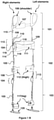
- the said apparatus comprising one or more straps/belts for waist 111, back 107 or shoulders 106; and one or more body adaptable shoulder element 101, thigh element 102, leg element 103 and a structure 601 having a body adaptable shaped profile to carry loads wherein upper side of structure is mounted at back strap 107 using moveable securing means characterized in that the structure 601 may form a platform or a cantilever beam which may transmit the load at the head to the belt and further the belt may transfer the load to the leg and finally to the ground.
- the present invention relates to an apparatus and method embodying an improved belt for body support and for assisting body during heavy lifting, kneeling, bending and walking. More particularly, the belt (referred also as apparatus at various instances in the specification) employs a single point torque adjusting mechanical assembly with an adjustable hinge along with resilient means which stores potential energy when the user alters posture from a neutral position and helps the body to return to the neutral position.
- neutral posture may be a posture where the joints are not bent and the spine and legs are aligned and are not twisted.
- load may be used interchangeably and point to similar meaning.
- resilient means may be an object which is capable to recoil or spring back into shape after bending, stretching or being compressed.
- Resilient means may comprise a spring, hydraulics pneumatics, elastic strand, elastic rope, band and the like.
- the resilient means may be powered or unpowered.
- muscleculoskeletal activities may comprise human actions further comprising kneeling, sitting, walking, running, up/down bending, bending forward/backward and left/right rotation, carrying and picking the load, and other similar activities for various durations and frequency.
- FIG. 1 a representation of the belt is illustrated in accordance with an embodiment of the present invention.
- Element at left side of user may be called as left-element and the element at the right side of user may be called as right-element.
- Each longitudinal element may be made of at least two or three sub-elements having enlargement and engagement-disengagement arrangement.
- Upper sub-element attached with shoulder may be called as Shoulder-element 101
- sub-element attached with thigh may be called as thigh-element 102
- sub-element attached with leg may be called as leg-element 103.
- Each sub-element of a longitudinal element is adjustable in size and may be connected via one or two hinge mechanism 104 connectively coupled with single point torque/load adjusting mechanical assembly 113 and having resilient means 105 or powered resilient means or both.
- Upper end of shoulder element 101 may have cushioned strap 106 and the lower end of the shoulder element 101 is connected to upper end of thigh-element 102 via hinge and single point torque adjusting mechanical assembly 104.
- the cushioned strap 106 may grip the shoulder and the shoulder element 101 together.
- Shoulder element 101 of both sides may be connected via resilient element called back strap 107.
- Upper-end of the Shoulder element 101 may have an arrangement of adjusting the length of the Shoulder-element 101 and has flexibility and size adjustment mechanism 115 to make it ergonomically comfortable.
- the mentioned hinge mechanism 104 is connectively coupled with single point torque/load adjusting mechanical assembly 113 which movably may connect the lower end of shoulder element 101 and upper end of thigh-element 102.
- the hinge mechanism comprises of a load adjusting pipe 108 moveably attached with lower end of shoulder element 101 and has button 109 mechanism to fix load adjusting pipe 108 at a particular position. Particular position of load adjusting pipe 108 determines the load and torque of the hinge mechanism.
- An inextensible and flexible element or rope 114 connects upper end of resilient means 105 or powered resilient means to the hinge-pin 110 and passes via single point 116 located at lower end of load adjusting pipe 108.
- Hinge pin 110 may be a part of hinge mechanism fixed with lower end of shoulder-elements 101 and may movably connect to shaft 118 of the hinge.
- the other end of resilient element 105 or powered resilient element may be fixed to the lower end of the thigh-element 102.
- the apparatus when the user bends down, the apparatus may generate a force of tension in inextensible and flexible elements which transfer the load to resilient means 105.
- the potential energy gets stored in resilient means 105 and the hinge mechanism 104 connectively coupled with single point torque/load adjusting mechanical assembly 113 may provide counter support to user's back and waist through the waist strap.
- the stored potential energy assists the user when user tends to bend-up and stand up.
- Different positions of mentioned load adjusting pipe 108 or different combination of r and 1 ensure the different length of lever arm of the hinge and make different elongations to resilient means 105. If load adjusting pipe 108 is positioned to increase lever arm length, then the hinge may provide more counter torque or increase the counter load resulting the hinge to bear more load and vice-versa.
- the length of flexible inextensible element or rope 114 is equivalent to sum of lengths of r (OA) and 1 (AB) and remain same for different lever arm length.
- Each of the thigh elements 102 or longitudinal element may be movably connected with the waist belt 111.
- Waist belt 111 may be cushioned flexible element meant to wrap around the waist or body of the user. It may connect both longitudinal elements at the waist together and to the waist of user.
- Lower end of thigh-element 102 has pad like structure and cushioned straps 112 that may grip the thigh-element 102 to the thigh.
- Pad like structure may be adjusted at different position at thigh-element 102 and have different ergonomics and user friendly shape and arrangement that enable to wear the belt over cloths such as Skirts and Sarees without need of straps or tying around thighs.
- the lower end of thigh-element 102 is moveably connected to the leg-element 103 via another hinge 104 cum load/torque adjusting mechanical assembly 113 similar to described hinge mechanism 104 connectively couple with single point torque/load adjusting mechanical assembly 113 at lower end of Shoulder-element 101 but later is for knee.
- Lower end of leg-element 103 may have padded and cushioned strap 117 to grip leg-elements 103 with the leg and also have foot element 120 moveably secured with the lower end of leg element 103 to transfer the load and weight to ground.
- the hinge mechanism 104 that is connectively coupled with single point torque/load adjusting mechanical assembly 113 may support and assist the knees of user. When user sits-down or when he folds the leg by using the knees then the potential energy may get stored in the resilient mean 105 or powered resilient means. The same energy supports the user and assists the user during standing-up or in musculoskeletal activities.
- a flexible and adjustable mechanism 115 may be provided above the load adjusting pipe 108 and below the shoulder element 101 to change the height of the apparatus for the concerned user. This mechanism may provide better ergonomics to the apparatus for compliance in the user-apparatus working environment.
- 502 which lies inside shoulder element 101 with springs or resilient mean, helps in size adjustment and gets compressed when user bends down and return in normal shape when user bend up to ensures shoulder element moves in accordance with shoulder.
- leg-element 103 may transfer the weight and load from the user to ground and lower part of body thus minimizing the adverse consequences of lifting heavy load and strenuous activities. Its assists the also when user is half seated, stand up, seats frequently.
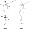
- FIG. 2 which illustrates apparatus and methods for reducing the effort using the counter torque produced by the hinge mechanism 104 connectively coupled with single point torque/load adjusting mechanical assembly 113 in accordance with an embodiment of the present subject matter.
- the upper part of the hinge mechanism 104 connectively coupled with single point torque/load adjusting mechanical assembly 113 may constitute the load adjusting pipe 108 with button 109 mechanism.
- the load adjusting pipe may have groves or holes in it to engage the button 109 as per the required load.
- Length OA denotes the lever arm which non-linearly varies the torque and counter torque in the apparatus as torque is directly proportional to lever arm and the force applied. Point O may always remain fixed.
- the load adjusting pipe 108 may slide over the lower end of shoulder element 101 to change the lever arm length.
- the stored potential energy may exert a force on load adjusting pipe at the single point A at distance AO from point O which may eventually produce torque due to the lever arm.
- a single point torque adjusting mechanical assembly 113 adjusts the torque by adjusting the lever arm (r) length such that the lower/second end D of resilient means 105 needs not to be shifted.
- the length OD and sum of lengths of 1 and r remains constant; and do not require adjusting pre load/tension in resilient means 105; and comprises of load adjusting pipe 108 and flexible inextensible element or wire rope 114 wherein load adjusting pipe has single point (A) 116 at its lower end.
- Load adjusting pipe 108 can be slide over the lower end of shoulder element 101 and thigh elements 102 to change the lever arm length to produce non-linear variable counter torque to reduce the effort for musculoskeletal actions.
- the load adjusting pipe 108 can be locked/unlocked with lower end of shoulder element 101 using engagement/disengagement button 109; and optionally comprises of extended mechanism to facilitate locking/unlocking and sliding of load adjusting pipe 108 to adjust the torque; and single point torque adjusting mechanical assembly can be used/applied in other applications such as humanoid, exo-skeletons and other applications and equipments.
- FIG. 2B a similar mechanism with alternative arrangements of the hinge with the load adjusting pipe 108 and the resilient means is illustrated in Figure 2B with an embodiment of the present subject matter. This configuration may work similar in functionality with Figure 2A but may have different orientation as shown in Figure 2 B
- an extended mechanism 301 for adjusting load is illustrated with an embodiment of the present subject matter.
- the apparatus may be equipped with an extended mechanism 301 to enable the user to adjust the torque by adjusting load pipe 108 and engage/disengage the button 109.
- the apparatus may comprise one or more extended mechanisms 301 for adjusting load for hinge 104 cum load adjusting mechanical assembly 113 at the waist and another hinge 104 cum load adjusting mechanical assembly 113 at knee for leg element103.
- the extended mechanism 301 for adjusting the load may be positioned at the front of waist or elsewhere which may be easily accessible by the user as preferred than that of position where the hinge mechanism 104 connectively coupled with single point torque/load adjusting mechanical assembly 113 is located.
- the lock mechanism may help the user to adjust the torque.
- the extended mechanism 301 for adjusting the load may comprise a lock element 302, one or more wires 303 connected to the button 109 which passes through the lock element 302 and may be attached to the load adjusting pipe 108 by fastening means, a tension spring 304 connected to a fixed support at one end and the load adjusting pipe 108 at the other end, a compression spring 305 connected to the button 109 such that the compressive force makes the button 109 to insert in the holes or slots in the load adjusting pipe 108.
- the wires 306 are meant to slide the load pipe 108 and wires 307 are meant for engaging/disengaging button 109.
- One or more wires 306, 307 may be locked at the locking element 302.
- buttons 109 and load adjusting pipe 108 can slide when user moves the knob 308 from the lock element 302.
- button 109 is locked due to compression spring 305.
- Load adjusting pipe 108 is set for minimum lever arm length due to default action of tension spring 304.
- the button 109 auto engages itself when next or previous slot arrives against it because of the compressive action of the compression spring 305.
- the tension spring 304 allows load adjusting pipe to return to the minimum position as the tension in the spring forces the load adjusting pipe 108 to come towards hinge pin 110 or toward axis/shaft 118 of rotation of hinge.
- Wires 303 corresponding to one load adjusting pipe 108 is such that it is one continuous wire 303 though it appears as two wires from the lock element 302. Each one main wire 303 may correspond to their respective left or right load adjusting pipe 108.
- a single point torque adjusting mechanical assembly wherein mechanical assembly non-linearly varies the torque by adjusting a lever arm length such that fixed end of a resilient means 105' need not be displaced; the said mechanism comprising of an upper element 101', a lower element 102', resilient means 105' with fixed end and free end 119', flexible inextensible element or rope 114', hinge pin 110' and shaft 118', load/torque adjusting means 113' having a single point at its free end 116'.
- the mechanical assembly is such that the upper element 101' is moveably secured with lower element 102' by the hinge pin 110' and shaft 118', and one end of the load adjusting means 108 is moveably connected with a secured end of upper element 101'.
- the flexible inextensible element or rope 114' is moveably secured with/between the free end 119' of the resilient means and hinge pin 110' and such flexible inextensible element 114' passes through the free end 116 of the load adjusting means 105'.
- the length of flexible inextensible element or rope 114' is equivalent or equal to sum of distance between hinge pin 110' and free end 116' of load adjusting means 108' and distance between free end 116' of load adjusting means and the free end 119' of the resilient means.
- the said load adjusting means 108' can slide over the lower end of upper element 101' to change the lever arm length to produce non-linear variable counter torque.
- Hinge pin 110' and shaft 118' can be replaced as a ball and socket joint.
- the adjustment of pre load/tension in resilient means 105' is not required in this mechanism.
- the load adjusting means 105' can be locked/unlocked with lower end of upper element 101' using engagement/disengagement means 109'.
- the mechanism optionally comprises of extended mechanism to facilitate locking/unlocking and sliding of load adjusting means 108' to adjust the torque.
- FIG. 5 various positions of the apparatus with element showing exploded view and assembled view wherein the load transfer from the apparatus to the ground by enabling a foot element 120 is illustrated with an embodiment of the present subject matter.
- the working of the belt is illustrated at various positions with an embodiment of the present subject matter.
- Figure 1-A an exploded view of the apparatus is represented wherein from the top to the bottom all elements comprising the shoulder element 101, load adjusting pipe 108, button 109, rope 114, hinge 104, resilient means 105, the lower hinge and resilient means and the foot element 120 for transferring the load at the ground.
- the assembled apparatus is represented at neutral position with no bending or twisting of any joints or muscles by the user (not shown).
- the hinges which may be at neutral position or posture may be at zero-degree bend and resilient means 105 may also be in an unloaded position.
- Figure 4-C the assembled belt is represented along with a sitting posture.
- the extended leg element 103 may have the foot element 120 which may transfer the load from the body to the leg element 103 and finally to the ground.
- all the hinges at the waist and the knees and all the resilient means 105 are into action to overcome the load acting on the user.
- FIG. 6 an addition of structure 601 to carry loads which may be pivoted at pivot points 602 mechanical element connecting both 3D or simple hinges 603 and upper side of structure is mounted at back strap 107 is illustrated with an embodiment of the present subject matter.
- the apparatus may also be equipped by a load carrying structure which may be attached to the back of the apparatus near at mechanical element connecting both 3D hinges 603 and uppers side of structure is mounted at back strap 107.
- the 3D hinges 603 are mounted on lower end (inner pipe) of shoulder element.
- the structure 601 may be a continuous Z shaped profile if viewed from the left side of the user.
- the upper part of the structure 601 may be used to carry load at the head.
- the upper part of the structure 601 may form a platform or a cantilever beam which may transmit and share the load at the head to the belt and further the belt may transfer the load to the leg and finally to the ground.
- the load may also be carried at the back with help of the lower platform which may also work as a load carrying beam.
- the load on the lower part may be transferred to the apparatus by the insertion of the pivot which may join the structure 601 and the apparatus at the pivot point. Heavy lifting of loads comprising sack of grains, cement or any other material may be performed with ease by the apparatus attached with the structure 601.
- Pivoted at mechanical element connecting both 3d hinges 603 and uppers side of structure is mounted at back strap 107.
- the 3D hinges 603 are mounted on lower end (inner pipe) of shoulder element.
- the attachment of the structure 601 may be so adjusted that the orientation of the structure remains vertical.
- the structure 601 may be pivoted at pivot points 602 at mechanical element connecting both 3D hinges 603 and uppers side of structure is mounted at back strap 107.
- the 3D hinges 603 are mounted on lower end (inner pipe) of shoulder element which may enable swivelling of the structure in multi direction when user performs actions comprising flexion, bending, bending with rotation or unlevelled stepping.
- the incorporation of the multidirectional joints 601 results in the correct vertical orientation of the structure even if user' posture may not be vertical.
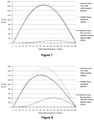
- Table 1 represents a data of a user with 70 kg self-weight with height 180 cm and lifting a load of 20 kg with lever arm of 1 cm.
- Table 1 Sr. No. Angle ° (degrees) Load (N-cm) on User's waist without wearing apparatus Assistive Torque provided by Apparatus Reduced Load (N-cm) on User's waist after wearing apparatus.
- r(OA) 1 1 0 0 0 0 2 30 865 6 859 3 60 1499 37 1462 4 90 1731 83 1648 5 120 1499 103 1396 6 150 866 72 793 7 180 0 0 0
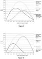
- Table 4 represents a data of a user with 70 kg self-weight with height 180 cm and lifting a load of 20 kg with lever arm of 4 cm.
- Table 4 Sr. No. Angle ° (degrees) Load (N-cm) on User's waist without wearing apparatus+ Assistive Torque provided by Apparatus Reduced Load (N-cm) on User's waist after wearing apparatus.
- the maximum torque may be obtained at lever arm 4 cm which may provide a maximum arm length thus resulting in a maximum torque.
- a maximum torque at each lever arm length may be observed at angle 80-110 degrees.
Landscapes
- Health & Medical Sciences (AREA)
- Animal Behavior & Ethology (AREA)
- Veterinary Medicine (AREA)
- Public Health (AREA)
- General Health & Medical Sciences (AREA)
- Life Sciences & Earth Sciences (AREA)
- Engineering & Computer Science (AREA)
- Rehabilitation Therapy (AREA)
- Physical Education & Sports Medicine (AREA)
- Pain & Pain Management (AREA)
- Epidemiology (AREA)
- Textile Engineering (AREA)
- Nursing (AREA)
- Orthopedic Medicine & Surgery (AREA)
- Biomedical Technology (AREA)
- Heart & Thoracic Surgery (AREA)
- Vascular Medicine (AREA)
- Mechanical Engineering (AREA)
- Robotics (AREA)
- Rehabilitation Tools (AREA)
- Orthopedics, Nursing, And Contraception (AREA)
- Manipulator (AREA)
Claims (12)
- Mechanische Einzelpunkt-Last/Drehmoment-Einstellanordnung (113), wobei die mechanische Einzelpunkt-Last/Drehmoment-Einstellanordnung (113) das Drehmoment nichtlinear durch Einstellen einer Hebelarmlänge derart variiert, dass das feste Ende eines elastischen Mittels (105') nicht verschoben werden muss; wobei die mechanische Einzelpunkt-Last/Drehmoment-Einstellanordnung (113) umfasst:ein oberes Element (101');ein unteres Element (102');ein elastisches Mittel (105') mit einem festen Ende und einem freien Ende (119'), wobei das feste Ende an dem unteren Element (102) befestigt ist;ein flexibles, nicht dehnbares Element oder Seil (114');einen Scharnierstift (110') und eine Welle (118');ein Last/Drehmoment-Einstellmittel (113'), das einen einzelnen Punkt (116') an seinem freien Ende aufweist;wobei das obere Element (101') mit dem unteren Element (102') durch den Scharnierstift (110') und die Welle (118') beweglich gesichert ist und ein Ende eines Lasteinstellmittels (108') des Last/Drehmoment-Einstellmittels (113') mit einem gesicherten Ende des oberen Elements (101') beweglich verbunden ist; undwobei das flexible, nicht dehnbare Element oder Seil (114') beweglich mit/zwischen dem freien Ende (119') des elastischen Mittels (105') und dem Scharnierstift (110') gesichert ist und durch den Einzelpunkt (116') des Lasteinstellmittels (108') am freien Ende verläuft;wobei die Länge des flexiblen, nicht dehnbaren Elements oder Seils (114') entsprechend oder gleich der Summe des Abstands zwischen dem Scharnierstift (110') und dem Einzelpunkt (116') des Lasteinstellmittels (108') am freien Ende und dem Abstand zwischen dem Einzelpunkt (116') des Lasteinstellmittels (108') am freien Ende und dem freien Ende (119') des elastischen Mittels (105') ist, wobei diese Summe konstant bleibt;wobei das Lasteinstellmittel (108') über das untere Ende des oberen Elements (101') gleiten kann, um die Länge des Hebelarms zu verändern und ein nichtlineares, variables Gegendrehmoment zu erzeugen.
- Mechanische Einzelpunkt-Last/Drehmoment-Einstellanordnung (113) nach Anspruch 1, wobei eine Einstellung der Vorlast/Spannung im elastischen Mittel (105') nicht erforderlich ist, um das Drehmoment einzustellen.
- Mechanische Einzelpunkt-Last/Drehmoment-Einstellanordnung (113) nach Anspruch 1, wobei das Lasteinstellmittel (108') mit dem unteren Ende des oberen Elements (101') unter Verwendung von Eingriffs-/Entriegelungsmitteln (109') verriegelt/entriegelt werden kann.
- Mechanische Einzelpunkt-Last/Drehmoment-Einstellanordnung (113) nach Anspruch 1, wobei der Mechanismus optional einen verlängerten Mechanismus umfasst, um das Verriegeln/Entriegeln und Verschieben der Lasteinstellmittel (108') zum Einstellen des Drehmoments zu erleichtern.
- Verfahren zum Verwenden einer mechanischen Last/Drehmoment-Einstellanordnung (113) nach einem der vorhergehenden Ansprüche, um das Drehmoment nichtlinear zu verändern, indem eine Hebelarmlänge derart eingestellt wird, dass das feste Ende eines elastischen Mittels (105') nicht verschoben werden muss.
- Vorrichtung zur Unterstützung von Muskel-Skelett-Aktivitäten, wobei die Vorrichtung einen Benutzer in die Lage versetzt, die Last auf Körperteile zu verteilen und die Anstrengung zu überwinden, die erforderlich ist, um in eine neutrale Position zurückzukehren, und zwar durch Anwenden eines Gegendrehmoments, indem potentielle Energie in einem elastischen Mittel (105) gespeichert wird, wobei die Vorrichtung umfasst:ein oder mehrere mechanische Längselemente (103);einen oder mehrere einstellbare Scharniermechanismen (104);eine oder mehrere mechanische Einzelpunkt-Last/Drehmoment-Einstellanordnungen (113) nach Anspruch 1;eine Anordnung für Flexibilitäts- und Höheneinstellmittel (115);einen oder mehrere Riemen/Gürtel für Taille (111), Rücken (107) oder Schultern (106); undein oder mehrere an den Körper anpassbare Schulterelemente (101) oder Oberschenkelelemente (102), wobei das Gegendrehmoment aufgebaut wird, wenn der Benutzer durch das Durchführen von Muskel-Skelett-Aktivitäten aus der neutralen Position wechselt, was auf die im elastischen Mittel (105) gespeicherte potentielle Energie zurückzuführen ist;wobei die mechanische Einzelpunkt-Last/Drehmoment-Einstellanordnung (113) zusammen mit dem einstellbaren Scharniermechanismus (104), der an den elastischen Mitteln (105) angebracht ist, dafür verantwortlich ist, ein Gegendrehmoment zu erzeugen, um den Benutzer in die neutrale Position zurückzubringen;und das Gegendrehmoment nichtlinear variiert werden kann, indem die mechanische Einzelpunkt-Last/Drehmoment-Einstellanordnung (113) verwendet wird, indem ein Längsabstand zwischen einem Scharnierstift (110) und einem einzelnen Punkt (116) eingestellt wird, wobei eine Welle (118) als eine Drehachse wirkt und der Längsabstand als Hebelarm wirkt.
- Vorrichtung nach Anspruch 7, wobei die Vorrichtung über/unter der Kleidung am Rücken getragen werden kann und Schulterpolsterriemen, Knieschalen und einen Taillengürtel zum Greifen aufweist, der in einem Anzug/einer Jacke verwendet/integriert werden kann.
- Vorrichtung nach Anspruch 7, wobei durch die potentielle Energie im elastischen Mittel (105) eine Kraft auf den einstellbaren Scharniermechanismus (104) ausgeübt werden kann, die später ein Drehmoment mit der mechanischen Einzelpunkt-Last/Drehmoment-Einstellanordnung (113) erzeugt und eine Hilfskraft bereitstellt, wenn der Benutzer einen Schritt oder eine Aktion beim Gehen, Bücken, Sitzen, Knien, Drehen ausführt.
- Vorrichtung nach Anspruch 7, wobei die Vorrichtung optional einen verlängerten Mechanismus umfasst, um das Verriegeln/Entriegeln und Verschieben des Lasteinstellmittels (108') zum Einstellen des Drehmoments zu erleichtern.
- Vorrichtung nach Anspruch 7, wobei die Last und das Hilfsdrehmoment an den Hüft- und Kniegelenken eingestellt werden können und das Hilfsdrehmoment entsprechend dem Beugewinkel maximal und minimal ist und Unterstützung bietet, wenn die Last am Knie und an der Hüfte maximal bzw. minimal ist, und das Muster und Profil des Hilfsdrehmoments einstellbar ist.
- Vorrichtung nach Anspruch 7, wobei die Vorrichtung für eine korrekte menschliche Haltung sorgt und die Verformung der Wirbelsäule korrigiert und die menschliche Haltung und Wirbelsäule gestützt hält.
- Beinvorrichtung zur Unterstützung von Muskel-Skelett-Aktivitäten, wobei durch die Beinvorrichtung ein Benutzer die Möglichkeit hat, die Last auf die Knie/Beine zu verteilen und die Anstrengung zu überwinden, die erforderlich ist, um das Bein und das Kniegelenk in die neutrale Position zurückzubringen, indem ein Gegendrehmoment eingesetzt wird, indem potentielle Energie in einem elastischen Mittel (105) gespeichert und die Last auf den Boden geleitet wird, wobei die Vorrichtung umfasst:ein oder mehrere mechanische Längselemente (103);einen oder mehrere einstellbare Scharniermechanismen (104);eine oder mehrere mechanische Einzelpunkt-Last/Drehmoment-Einstellanordnungen (113) nach Anspruch 1;eine oder mehrere Beinschalen (117);optional ein oder mehrere Fußelemente (120); undeine Anordnung für Flexibilitäts- und Höheneinstellmittel;wobei das Gegendrehmoment aufgebaut wird, wenn der Benutzer durch das Durchführen von Muskel-Skelett-Aktivitäten aus der neutralen Beinposition wechselt, was auf die im elastischen Mittel (105) gespeicherte potentielle Energie zurückzuführen ist;wobei die mechanische Einzelpunkt-Last/Drehmoment-Einstellanordnung (113), die mit einem am elastischen Mittel (105) angebrachten einstellbaren Scharniermechanismus (104) verbunden ist, dafür verantwortlich ist, ein Gegendrehmoment zu erzeugen, um das Bein des Benutzers in die neutrale Position zurückzubringen;und das Gegendrehmoment nichtlinear variiert werden kann, indem die mechanische Einzelpunkt-Last/Drehmoment-Einstellanordnung (113) zum Einstellen eines Längsabstands zwischen einem Scharnierstift (110) und einem einzelnen Punkt (116) verwendet wird, wobei eine Welle (118) als Drehachse wirkt und der Längsabstand als Hebelarm wirkt;und die Last/das Gewicht durch ein Fußelement (120) auf den Boden übertragen wird.
Applications Claiming Priority (2)
| Application Number | Priority Date | Filing Date | Title |
|---|---|---|---|
| IN3750DE2014 | 2014-12-18 | ||
| PCT/IB2015/059722 WO2016098039A1 (en) | 2014-12-18 | 2015-12-17 | An improved belt system for body support |
Publications (3)
| Publication Number | Publication Date |
|---|---|
| EP3233014A1 EP3233014A1 (de) | 2017-10-25 |
| EP3233014A4 EP3233014A4 (de) | 2018-05-23 |
| EP3233014B1 true EP3233014B1 (de) | 2022-02-16 |
Family
ID=56126039
Family Applications (1)
| Application Number | Title | Priority Date | Filing Date |
|---|---|---|---|
| EP15869448.9A Active EP3233014B1 (de) | 2014-12-18 | 2015-12-17 | Mechanische einheit zur kraft/momenteinstellung mit einem einzelpunkt |
Country Status (5)
| Country | Link |
|---|---|
| US (1) | US10376402B2 (de) |
| EP (1) | EP3233014B1 (de) |
| CN (1) | CN106659629B (de) |
| RU (1) | RU2677919C1 (de) |
| WO (1) | WO2016098039A1 (de) |
Families Citing this family (45)
| Publication number | Priority date | Publication date | Assignee | Title |
|---|---|---|---|---|
| JP1541976S (de) * | 2015-05-18 | 2016-01-18 | ||
| US10543391B2 (en) * | 2016-07-01 | 2020-01-28 | Ji Xiao | Exercise device and upright posture retainer for upper body |
| EP3318241B1 (de) * | 2016-11-08 | 2020-04-29 | noonee AG | Tragbare haltungsunterstützungsvorrichtung |
| FR3061445B1 (fr) * | 2016-12-29 | 2019-05-24 | Safran Electronics & Defense | Dispositif de liaison pour structure d'exosquelette facilitant le portage de charges pendant la marche ou la course |
| JP7054801B2 (ja) * | 2017-07-18 | 2022-04-15 | パナソニックIpマネジメント株式会社 | アシスト装置及びアシスト方法 |
| CN110202543B (zh) * | 2017-09-07 | 2022-12-27 | 重庆市牛迪科技发展有限公司 | 一种外骨骼 |
| JP7142252B2 (ja) * | 2017-10-31 | 2022-09-27 | パナソニックIpマネジメント株式会社 | アシスト装置、アシスト装置の作動方法及びプログラム |
| EP3536297A1 (de) | 2018-02-23 | 2019-09-11 | LG Electronics Inc. | Tragbare unterstützungsvorrichtung mit effiziente abgabe von unterstützungskraft |
| US20190274912A1 (en) * | 2018-03-09 | 2019-09-12 | Lg Electronics Inc. | Wearable assistive device having improved waist support |
| CN108748116A (zh) * | 2018-08-31 | 2018-11-06 | 广州市海同机电设备有限公司 | 一种自适应柔性外骨骼 |
| CN108839001B (zh) * | 2018-09-03 | 2024-07-02 | 广州海同工业技术有限公司 | 一种可调节蓄能助力外骨骼 |
| JP7249756B2 (ja) * | 2018-10-26 | 2023-03-31 | 株式会社イノフィス | 腰部補助装置及び腰部補助装置用付勢装置 |
| CN109732564A (zh) * | 2018-11-23 | 2019-05-10 | 上海谐趣技术有限公司 | 一种腰椎负重辅助外骨骼 |
| CN109464267B (zh) * | 2018-11-29 | 2024-08-02 | 成都云鼎康德科技有限公司 | 一种膝关节助力机构 |
| US11141344B2 (en) * | 2018-12-27 | 2021-10-12 | Chin-Sung Yang | Assistant apparatus for degenerative joint |
| CN109590991B (zh) * | 2018-12-29 | 2022-03-25 | 中国科学院深圳先进技术研究院 | 外骨骼机器人 |
| CA3138604A1 (en) * | 2019-05-02 | 2020-11-05 | Mawashi Science & Technology Inc. | Body weight support system for exoskeletons and method of using the same |
| DE102019119645B4 (de) * | 2019-07-19 | 2022-11-10 | Ottobock Se & Co. Kgaa | Orthopädietechnische Einrichtung |
| DE102020119166A1 (de) * | 2020-07-21 | 2022-01-27 | Ottobock Se & Co. Kgaa | Orthopädietechnische Einrichtung zum Unterstützen einer unteren Extremität eines Benutzers |
| USD992741S1 (en) * | 2020-10-22 | 2023-07-18 | Samsung Electronics Co., Ltd. | Wearable assistance robot |
| USD992122S1 (en) * | 2020-10-22 | 2023-07-11 | Samsung Electronics Co., Ltd. | Wearable assistance robot |
| DE202020106660U1 (de) * | 2020-11-19 | 2020-12-04 | Dominik Heinzelmann | Hebehilfe |
| DE102021202433B3 (de) | 2021-03-12 | 2022-09-01 | Fraunhofer-Gesellschaft zur Förderung der angewandten Forschung eingetragener Verein | Extremitätenunterstützungsvorrichtung und Verfahren zum Heben, Halten und/oder Tragen einer Last und/oder zum Ausführen von Überkopftätigkeiten |
| CN113199461B (zh) * | 2021-05-24 | 2022-12-27 | 山东大学 | 一种基于柔性连续体的建筑作业机械臂及辅助作业装置 |
| CN115488857A (zh) * | 2021-06-17 | 2022-12-20 | 广州视源电子科技股份有限公司 | 外骨骼装备 |
| CN113771004B (zh) * | 2021-08-12 | 2023-04-18 | 重庆交通大学 | 穿戴型随动助力外骨骼身体姿态控制装置 |
| FR3132044B1 (fr) * | 2022-01-21 | 2023-12-22 | Robotiques 3 Dimensions | Exosquelette d’assistance au maintien en posture penchée en avant et au redressement |
| USD1022223S1 (en) * | 2022-05-20 | 2024-04-09 | Samsung Electronics Co., Ltd. | Wearable robot |
| USD1022224S1 (en) * | 2022-05-20 | 2024-04-09 | Samsung Electronics Co., Ltd. | Wearable robot |
| USD1021990S1 (en) * | 2022-05-20 | 2024-04-09 | Samsung Electronics Co., Ltd. | Wearable robot |
| USD1023096S1 (en) * | 2022-05-20 | 2024-04-16 | Samsung Electronics Co., Ltd. | Wearable robot |
| USD1022222S1 (en) * | 2022-05-20 | 2024-04-09 | Samsung Electronics Co., Ltd. | Wearable robot |
| USD1022221S1 (en) * | 2022-05-20 | 2024-04-09 | Samsung Electronics Co., Ltd. | Wearable robot |
| USD1057964S1 (en) * | 2022-10-20 | 2025-01-14 | Samsung Electronics Co., Ltd. | Wearable robot |
| USD1058628S1 (en) | 2022-10-20 | 2025-01-21 | Samsung Electronics Co., Ltd. | Wearable robot |
| USD1058629S1 (en) | 2022-10-20 | 2025-01-21 | Samsung Electronics Co., Ltd. | Wearable robot |
| USD1066692S1 (en) * | 2022-10-20 | 2025-03-11 | Samsung Electronics Co., Ltd. | Wearable robot |
| USD1057963S1 (en) | 2022-10-20 | 2025-01-14 | Samsung Electronics Co., Ltd. | Wearable robot |
| USD1057788S1 (en) | 2022-10-20 | 2025-01-14 | Samsung Electronics Co., Ltd. | Wearable robot |
| USD1066693S1 (en) * | 2022-10-20 | 2025-03-11 | Samsung Electronics Co., Ltd. | Wearable robot |
| USD1059607S1 (en) * | 2022-10-20 | 2025-01-28 | Samsung Electronics Co., Ltd. | Wearable robot |
| USD1059606S1 (en) * | 2022-10-20 | 2025-01-28 | Samsung Electronics Co., Ltd. | Wearable robot |
| USD1058822S1 (en) | 2022-10-20 | 2025-01-21 | Samsung Electronics Co., Ltd. | Wearable robot |
| KR102755510B1 (ko) * | 2023-03-09 | 2025-01-21 | 임석민 | 하중지지용 보행보조장치 |
| CN117045203B (zh) * | 2023-09-23 | 2024-07-23 | 核工业总医院 | 一种风湿免疫科用强直性脊柱炎的检测装置 |
Family Cites Families (40)
| Publication number | Priority date | Publication date | Assignee | Title |
|---|---|---|---|---|
| US4632096A (en) | 1985-08-12 | 1986-12-30 | Harris Adam I | Automatically releasing knee brace |
| SU1528483A1 (ru) * | 1987-09-28 | 1989-12-15 | Ostapenko Oleg A | Устройство дл разгрузки позвоночника |
| US5016869A (en) | 1989-07-05 | 1991-05-21 | Applied Motion | Human bipedal locomotion device |
| US5090604A (en) * | 1990-07-24 | 1992-02-25 | The North Face | Backpack device |
| US5147261A (en) | 1991-03-06 | 1992-09-15 | Florida Orthopedics, Inc. | Lifting belt |
| DE19652416A1 (de) * | 1996-12-07 | 1998-06-10 | Braune Hans Juergen | Verfahren und orthopädisches Stützkorsett zur Stützung des menschlichen Oberkörpers in gebeugter Haltung |
| US6016869A (en) | 1997-10-31 | 2000-01-25 | Burts, Jr.; Boyce D. | Well kill additive, well kill treatment fluid made therefrom, and method of killing a well |
| US6041444A (en) | 1997-12-22 | 2000-03-28 | Mckinney; John | Component load supporting articulated waist belt |
| RU2165752C1 (ru) * | 2000-06-21 | 2001-04-27 | ЗАО Научно-производственный центр ОГОНЕК | Устройство для лечения больных с последствиями поражения центральной нервной системы и с повреждением опорно-двигательного аппарата |
| US6783555B2 (en) * | 2000-10-27 | 2004-08-31 | Mark R. Kuhn | Gait orthosis |
| DE102004008509B4 (de) * | 2003-03-29 | 2007-03-15 | Ruppersberg, Anneliese | Vorrichtung zum aktiven Aufrichten des Oberkörpers einer Person |
| US7549969B2 (en) * | 2003-09-11 | 2009-06-23 | The Cleveland Clinic Foundation | Apparatus for assisting body movement |
| CA2547270C (en) | 2003-12-15 | 2013-01-08 | Queen's University At Kingston | Lift assist device and method |
| JP4344314B2 (ja) | 2004-12-28 | 2009-10-14 | 本田技研工業株式会社 | 体重免荷アシスト装置および体重免荷アシストプログラム |
| JP4178187B2 (ja) * | 2005-01-26 | 2008-11-12 | 国立大学法人 筑波大学 | 装着式動作補助装置及び制御用プログラム |
| US7341025B1 (en) * | 2006-04-06 | 2008-03-11 | Lucky Bums, Inc. | Gait training harness |
| RU2362598C2 (ru) * | 2007-09-10 | 2009-07-27 | Общество с ограниченной ответственностью "Транспортные шагающие системы" | Пассивный грузовой экзоскелетон, коленный шарнир пассивного грузового экзоскелетона, компенсатор пассивного грузового экзоскелетона |
| CA2731612C (en) * | 2008-07-23 | 2018-03-20 | Berkeley Bionics | An exoskeleton and method for controlling a swing leg of the exoskeleton |
| CN101744450B (zh) * | 2008-12-08 | 2013-08-21 | 戴珊珊 | 均力背具 |
| KR20110018987A (ko) * | 2009-08-19 | 2011-02-25 | 박강산 | 다용도 보행보조기 |
| CN102548514B (zh) * | 2009-09-28 | 2014-07-30 | 学校法人东京理科大学 | 腰部辅助装置 |
| US8568344B2 (en) | 2009-10-23 | 2013-10-29 | Applied Neural Mechanics, Llc | Torso assist orthotic device |
| US20110098617A1 (en) | 2009-10-23 | 2011-04-28 | Ferguson Daniel L | Torso assist othosis |
| US9022956B2 (en) | 2011-06-10 | 2015-05-05 | U.S. Bionics, Inc. | Trunk supporting exoskeleton and method of use |
| RU2489130C1 (ru) * | 2011-11-28 | 2013-08-10 | Иван Анатольевич Родин | Простая конструкция компенсации веса человека при ходьбе и беге |
| US9610188B2 (en) * | 2012-01-11 | 2017-04-04 | Alliance Design And Development Group, Inc. | VRB cantilever-based unloader brace assembly |
| AU2013359408A1 (en) * | 2012-12-11 | 2014-06-19 | Ekso Bionics, Inc. | Reconfigurable exoskeleton |
| US9662261B2 (en) * | 2013-01-16 | 2017-05-30 | Ekso Bionics, Inc. | Fail-safe system for exoskeleton joints |
| CN103054692B (zh) * | 2013-01-29 | 2015-03-04 | 苏州大学 | 一种穿戴式下肢外骨骼助行机器人 |
| US10154937B2 (en) * | 2013-03-13 | 2018-12-18 | Ekso Bionics, Inc. | Gait orthotic device and method for protecting gait orthotic device and user from damage |
| US20140358053A1 (en) * | 2013-05-31 | 2014-12-04 | Case Western Reserve University | Power assisted orthosis with hip-knee synergy |
| CA2916674C (en) * | 2013-07-09 | 2020-09-29 | John THRELFALL | External structural brace apparatus |
| US20150025423A1 (en) * | 2013-07-19 | 2015-01-22 | Bionik Laboratories, Inc. | Control system for exoskeleton apparatus |
| JP6357628B2 (ja) * | 2014-01-30 | 2018-07-18 | 国立大学法人 筑波大学 | 装着式動作補助装置、及び装着式動作補助装置の操作ユニット |
| US10406676B2 (en) * | 2014-05-06 | 2019-09-10 | Sarcos Lc | Energy recovering legged robotic device |
| US10561568B1 (en) * | 2014-06-19 | 2020-02-18 | Lockheed Martin Corporation | Exoskeleton system providing for a load transfer when a user is standing and kneeling |
| CN105726266A (zh) * | 2014-12-24 | 2016-07-06 | 株式会社捷太格特 | 摆动关节装置、步行能力辅助装置、及控制摆动关节刚性的方法 |
| KR102094852B1 (ko) * | 2015-08-04 | 2020-03-30 | 삼성전자주식회사 | 토크 설정 방법 및 장치 |
| JP2018158403A (ja) * | 2017-03-22 | 2018-10-11 | 株式会社ジェイテクト | アシスト装置 |
| KR102469205B1 (ko) * | 2017-09-22 | 2022-11-21 | 삼성전자주식회사 | 운동 보조 장치 |
-
2015
- 2015-12-17 CN CN201580037573.4A patent/CN106659629B/zh active Active
- 2015-12-17 WO PCT/IB2015/059722 patent/WO2016098039A1/en not_active Ceased
- 2015-12-17 US US15/107,914 patent/US10376402B2/en active Active
- 2015-12-17 RU RU2017125491A patent/RU2677919C1/ru active
- 2015-12-17 EP EP15869448.9A patent/EP3233014B1/de active Active
Also Published As
| Publication number | Publication date |
|---|---|
| EP3233014A1 (de) | 2017-10-25 |
| CN106659629A (zh) | 2017-05-10 |
| EP3233014A4 (de) | 2018-05-23 |
| US20160317340A1 (en) | 2016-11-03 |
| CN106659629B (zh) | 2019-07-16 |
| RU2677919C1 (ru) | 2019-01-22 |
| WO2016098039A1 (en) | 2016-06-23 |
| US10376402B2 (en) | 2019-08-13 |
Similar Documents
| Publication | Publication Date | Title |
|---|---|---|
| EP3233014B1 (de) | Mechanische einheit zur kraft/momenteinstellung mit einem einzelpunkt | |
| KR101989218B1 (ko) | 외골격 및 착용자의 팔에 보조 토크를 제공하는 방법 | |
| US7744552B1 (en) | Personal upper body support device for lower back muscles assist | |
| US10561518B2 (en) | Wearable support structure and method of supporting a torso | |
| US11980563B2 (en) | Wearable assistance devices and methods of operation | |
| US9918892B2 (en) | External structural brace apparatus | |
| US20250367016A1 (en) | Wearable assistance devices and methods of operation | |
| US20220331947A1 (en) | Wearable exoskeleton with auxiliary back frame support | |
| US20250205102A1 (en) | Interface for an exoskeleton | |
| EP3019136A1 (de) | Externe strukturelle stützvorrichtung | |
| TW202208130A (zh) | 外骨骼搬運輔助裝置 | |
| CN110815171B (zh) | 为穿戴者的手臂提供辅助扭矩的外骨骼和方法 | |
| US7837274B2 (en) | Dynamic trunk support system | |
| US20140345625A1 (en) | Dynamic trunk leaning support | |
| RU2825044C1 (ru) | Активный модуль спины экзоскелета | |
| JP2019069124A (ja) | 座った状態において骨盤に伝わる上半身の重量を軽減する重量軽減装具 | |
| JP2017164384A (ja) | 補助具 | |
| Yao et al. | Design of Soft Power Suit for Lower Back Assistance | |
| WO2023121675A1 (en) | Therapeutic and physical conditioning pivoting system | |
| Kern et al. | A convertible spinal orthosis for controlled torso rigidity | |
| CA2638444A1 (en) | Dynamic trunk support system |
Legal Events
| Date | Code | Title | Description |
|---|---|---|---|
| STAA | Information on the status of an ep patent application or granted ep patent |
Free format text: STATUS: THE INTERNATIONAL PUBLICATION HAS BEEN MADE |
|
| PUAI | Public reference made under article 153(3) epc to a published international application that has entered the european phase |
Free format text: ORIGINAL CODE: 0009012 |
|
| STAA | Information on the status of an ep patent application or granted ep patent |
Free format text: STATUS: REQUEST FOR EXAMINATION WAS MADE |
|
| 17P | Request for examination filed |
Effective date: 20170711 |
|
| AK | Designated contracting states |
Kind code of ref document: A1 Designated state(s): AL AT BE BG CH CY CZ DE DK EE ES FI FR GB GR HR HU IE IS IT LI LT LU LV MC MK MT NL NO PL PT RO RS SE SI SK SM TR |
|
| AX | Request for extension of the european patent |
Extension state: BA ME |
|
| RIC1 | Information provided on ipc code assigned before grant |
Ipc: A61H 3/00 20060101AFI20180115BHEP |
|
| DAV | Request for validation of the european patent (deleted) | ||
| DAX | Request for extension of the european patent (deleted) | ||
| A4 | Supplementary search report drawn up and despatched |
Effective date: 20180420 |
|
| RIC1 | Information provided on ipc code assigned before grant |
Ipc: A61H 3/00 20060101AFI20180417BHEP |
|
| GRAP | Despatch of communication of intention to grant a patent |
Free format text: ORIGINAL CODE: EPIDOSNIGR1 |
|
| STAA | Information on the status of an ep patent application or granted ep patent |
Free format text: STATUS: GRANT OF PATENT IS INTENDED |
|
| INTG | Intention to grant announced |
Effective date: 20210908 |
|
| GRAS | Grant fee paid |
Free format text: ORIGINAL CODE: EPIDOSNIGR3 |
|
| GRAA | (expected) grant |
Free format text: ORIGINAL CODE: 0009210 |
|
| STAA | Information on the status of an ep patent application or granted ep patent |
Free format text: STATUS: THE PATENT HAS BEEN GRANTED |
|
| AK | Designated contracting states |
Kind code of ref document: B1 Designated state(s): AL AT BE BG CH CY CZ DE DK EE ES FI FR GB GR HR HU IE IS IT LI LT LU LV MC MK MT NL NO PL PT RO RS SE SI SK SM TR |
|
| REG | Reference to a national code |
Ref country code: GB Ref legal event code: FG4D |
|
| REG | Reference to a national code |
Ref country code: CH Ref legal event code: EP |
|
| REG | Reference to a national code |
Ref country code: DE Ref legal event code: R096 Ref document number: 602015077002 Country of ref document: DE |
|
| REG | Reference to a national code |
Ref country code: AT Ref legal event code: REF Ref document number: 1468439 Country of ref document: AT Kind code of ref document: T Effective date: 20220315 |
|
| REG | Reference to a national code |
Ref country code: IE Ref legal event code: FG4D |
|
| REG | Reference to a national code |
Ref country code: LT Ref legal event code: MG9D |
|
| REG | Reference to a national code |
Ref country code: NL Ref legal event code: MP Effective date: 20220216 |
|
| REG | Reference to a national code |
Ref country code: AT Ref legal event code: MK05 Ref document number: 1468439 Country of ref document: AT Kind code of ref document: T Effective date: 20220216 |
|
| PG25 | Lapsed in a contracting state [announced via postgrant information from national office to epo] |
Ref country code: SE Free format text: LAPSE BECAUSE OF FAILURE TO SUBMIT A TRANSLATION OF THE DESCRIPTION OR TO PAY THE FEE WITHIN THE PRESCRIBED TIME-LIMIT Effective date: 20220216 Ref country code: RS Free format text: LAPSE BECAUSE OF FAILURE TO SUBMIT A TRANSLATION OF THE DESCRIPTION OR TO PAY THE FEE WITHIN THE PRESCRIBED TIME-LIMIT Effective date: 20220216 Ref country code: PT Free format text: LAPSE BECAUSE OF FAILURE TO SUBMIT A TRANSLATION OF THE DESCRIPTION OR TO PAY THE FEE WITHIN THE PRESCRIBED TIME-LIMIT Effective date: 20220616 Ref country code: NO Free format text: LAPSE BECAUSE OF FAILURE TO SUBMIT A TRANSLATION OF THE DESCRIPTION OR TO PAY THE FEE WITHIN THE PRESCRIBED TIME-LIMIT Effective date: 20220516 Ref country code: NL Free format text: LAPSE BECAUSE OF FAILURE TO SUBMIT A TRANSLATION OF THE DESCRIPTION OR TO PAY THE FEE WITHIN THE PRESCRIBED TIME-LIMIT Effective date: 20220216 Ref country code: LT Free format text: LAPSE BECAUSE OF FAILURE TO SUBMIT A TRANSLATION OF THE DESCRIPTION OR TO PAY THE FEE WITHIN THE PRESCRIBED TIME-LIMIT Effective date: 20220216 Ref country code: HR Free format text: LAPSE BECAUSE OF FAILURE TO SUBMIT A TRANSLATION OF THE DESCRIPTION OR TO PAY THE FEE WITHIN THE PRESCRIBED TIME-LIMIT Effective date: 20220216 Ref country code: ES Free format text: LAPSE BECAUSE OF FAILURE TO SUBMIT A TRANSLATION OF THE DESCRIPTION OR TO PAY THE FEE WITHIN THE PRESCRIBED TIME-LIMIT Effective date: 20220216 Ref country code: BG Free format text: LAPSE BECAUSE OF FAILURE TO SUBMIT A TRANSLATION OF THE DESCRIPTION OR TO PAY THE FEE WITHIN THE PRESCRIBED TIME-LIMIT Effective date: 20220516 |
|
| PG25 | Lapsed in a contracting state [announced via postgrant information from national office to epo] |
Ref country code: PL Free format text: LAPSE BECAUSE OF FAILURE TO SUBMIT A TRANSLATION OF THE DESCRIPTION OR TO PAY THE FEE WITHIN THE PRESCRIBED TIME-LIMIT Effective date: 20220216 Ref country code: LV Free format text: LAPSE BECAUSE OF FAILURE TO SUBMIT A TRANSLATION OF THE DESCRIPTION OR TO PAY THE FEE WITHIN THE PRESCRIBED TIME-LIMIT Effective date: 20220216 Ref country code: GR Free format text: LAPSE BECAUSE OF FAILURE TO SUBMIT A TRANSLATION OF THE DESCRIPTION OR TO PAY THE FEE WITHIN THE PRESCRIBED TIME-LIMIT Effective date: 20220517 Ref country code: FI Free format text: LAPSE BECAUSE OF FAILURE TO SUBMIT A TRANSLATION OF THE DESCRIPTION OR TO PAY THE FEE WITHIN THE PRESCRIBED TIME-LIMIT Effective date: 20220216 Ref country code: AT Free format text: LAPSE BECAUSE OF FAILURE TO SUBMIT A TRANSLATION OF THE DESCRIPTION OR TO PAY THE FEE WITHIN THE PRESCRIBED TIME-LIMIT Effective date: 20220216 |
|
| PG25 | Lapsed in a contracting state [announced via postgrant information from national office to epo] |
Ref country code: IS Free format text: LAPSE BECAUSE OF FAILURE TO SUBMIT A TRANSLATION OF THE DESCRIPTION OR TO PAY THE FEE WITHIN THE PRESCRIBED TIME-LIMIT Effective date: 20220617 |
|
| PG25 | Lapsed in a contracting state [announced via postgrant information from national office to epo] |
Ref country code: SM Free format text: LAPSE BECAUSE OF FAILURE TO SUBMIT A TRANSLATION OF THE DESCRIPTION OR TO PAY THE FEE WITHIN THE PRESCRIBED TIME-LIMIT Effective date: 20220216 Ref country code: SK Free format text: LAPSE BECAUSE OF FAILURE TO SUBMIT A TRANSLATION OF THE DESCRIPTION OR TO PAY THE FEE WITHIN THE PRESCRIBED TIME-LIMIT Effective date: 20220216 Ref country code: RO Free format text: LAPSE BECAUSE OF FAILURE TO SUBMIT A TRANSLATION OF THE DESCRIPTION OR TO PAY THE FEE WITHIN THE PRESCRIBED TIME-LIMIT Effective date: 20220216 Ref country code: EE Free format text: LAPSE BECAUSE OF FAILURE TO SUBMIT A TRANSLATION OF THE DESCRIPTION OR TO PAY THE FEE WITHIN THE PRESCRIBED TIME-LIMIT Effective date: 20220216 Ref country code: DK Free format text: LAPSE BECAUSE OF FAILURE TO SUBMIT A TRANSLATION OF THE DESCRIPTION OR TO PAY THE FEE WITHIN THE PRESCRIBED TIME-LIMIT Effective date: 20220216 Ref country code: CZ Free format text: LAPSE BECAUSE OF FAILURE TO SUBMIT A TRANSLATION OF THE DESCRIPTION OR TO PAY THE FEE WITHIN THE PRESCRIBED TIME-LIMIT Effective date: 20220216 |
|
| REG | Reference to a national code |
Ref country code: DE Ref legal event code: R097 Ref document number: 602015077002 Country of ref document: DE |
|
| PG25 | Lapsed in a contracting state [announced via postgrant information from national office to epo] |
Ref country code: AL Free format text: LAPSE BECAUSE OF FAILURE TO SUBMIT A TRANSLATION OF THE DESCRIPTION OR TO PAY THE FEE WITHIN THE PRESCRIBED TIME-LIMIT Effective date: 20220216 |
|
| PLBE | No opposition filed within time limit |
Free format text: ORIGINAL CODE: 0009261 |
|
| STAA | Information on the status of an ep patent application or granted ep patent |
Free format text: STATUS: NO OPPOSITION FILED WITHIN TIME LIMIT |
|
| 26N | No opposition filed |
Effective date: 20221117 |
|
| PG25 | Lapsed in a contracting state [announced via postgrant information from national office to epo] |
Ref country code: SI Free format text: LAPSE BECAUSE OF FAILURE TO SUBMIT A TRANSLATION OF THE DESCRIPTION OR TO PAY THE FEE WITHIN THE PRESCRIBED TIME-LIMIT Effective date: 20220216 |
|
| PG25 | Lapsed in a contracting state [announced via postgrant information from national office to epo] |
Ref country code: IT Free format text: LAPSE BECAUSE OF FAILURE TO SUBMIT A TRANSLATION OF THE DESCRIPTION OR TO PAY THE FEE WITHIN THE PRESCRIBED TIME-LIMIT Effective date: 20220216 |
|
| REG | Reference to a national code |
Ref country code: CH Ref legal event code: PL |
|
| REG | Reference to a national code |
Ref country code: BE Ref legal event code: MM Effective date: 20221231 |
|
| PG25 | Lapsed in a contracting state [announced via postgrant information from national office to epo] |
Ref country code: LU Free format text: LAPSE BECAUSE OF NON-PAYMENT OF DUE FEES Effective date: 20221217 |
|
| PG25 | Lapsed in a contracting state [announced via postgrant information from national office to epo] |
Ref country code: LI Free format text: LAPSE BECAUSE OF NON-PAYMENT OF DUE FEES Effective date: 20221231 Ref country code: IE Free format text: LAPSE BECAUSE OF NON-PAYMENT OF DUE FEES Effective date: 20221217 Ref country code: CH Free format text: LAPSE BECAUSE OF NON-PAYMENT OF DUE FEES Effective date: 20221231 |
|
| PG25 | Lapsed in a contracting state [announced via postgrant information from national office to epo] |
Ref country code: BE Free format text: LAPSE BECAUSE OF NON-PAYMENT OF DUE FEES Effective date: 20221231 |
|
| PG25 | Lapsed in a contracting state [announced via postgrant information from national office to epo] |
Ref country code: HU Free format text: LAPSE BECAUSE OF FAILURE TO SUBMIT A TRANSLATION OF THE DESCRIPTION OR TO PAY THE FEE WITHIN THE PRESCRIBED TIME-LIMIT; INVALID AB INITIO Effective date: 20151217 |
|
| PG25 | Lapsed in a contracting state [announced via postgrant information from national office to epo] |
Ref country code: CY Free format text: LAPSE BECAUSE OF FAILURE TO SUBMIT A TRANSLATION OF THE DESCRIPTION OR TO PAY THE FEE WITHIN THE PRESCRIBED TIME-LIMIT Effective date: 20220216 |
|
| PG25 | Lapsed in a contracting state [announced via postgrant information from national office to epo] |
Ref country code: MK Free format text: LAPSE BECAUSE OF FAILURE TO SUBMIT A TRANSLATION OF THE DESCRIPTION OR TO PAY THE FEE WITHIN THE PRESCRIBED TIME-LIMIT Effective date: 20220216 |
|
| PG25 | Lapsed in a contracting state [announced via postgrant information from national office to epo] |
Ref country code: MC Free format text: LAPSE BECAUSE OF FAILURE TO SUBMIT A TRANSLATION OF THE DESCRIPTION OR TO PAY THE FEE WITHIN THE PRESCRIBED TIME-LIMIT Effective date: 20220216 |
|
| PG25 | Lapsed in a contracting state [announced via postgrant information from national office to epo] |
Ref country code: MC Free format text: LAPSE BECAUSE OF FAILURE TO SUBMIT A TRANSLATION OF THE DESCRIPTION OR TO PAY THE FEE WITHIN THE PRESCRIBED TIME-LIMIT Effective date: 20220216 |
|
| PG25 | Lapsed in a contracting state [announced via postgrant information from national office to epo] |
Ref country code: MT Free format text: LAPSE BECAUSE OF FAILURE TO SUBMIT A TRANSLATION OF THE DESCRIPTION OR TO PAY THE FEE WITHIN THE PRESCRIBED TIME-LIMIT Effective date: 20220216 |
|
| PG25 | Lapsed in a contracting state [announced via postgrant information from national office to epo] |
Ref country code: TR Free format text: LAPSE BECAUSE OF FAILURE TO SUBMIT A TRANSLATION OF THE DESCRIPTION OR TO PAY THE FEE WITHIN THE PRESCRIBED TIME-LIMIT Effective date: 20220216 |
|
| PGFP | Annual fee paid to national office [announced via postgrant information from national office to epo] |
Ref country code: DE Payment date: 20251211 Year of fee payment: 11 |
|
| PGFP | Annual fee paid to national office [announced via postgrant information from national office to epo] |
Ref country code: GB Payment date: 20251219 Year of fee payment: 11 |
|
| PGFP | Annual fee paid to national office [announced via postgrant information from national office to epo] |
Ref country code: FR Payment date: 20251229 Year of fee payment: 11 |