EP3233014B1 - A single point load/torque adjusting mechanical assembly - Google Patents
A single point load/torque adjusting mechanical assembly Download PDFInfo
- Publication number
- EP3233014B1 EP3233014B1 EP15869448.9A EP15869448A EP3233014B1 EP 3233014 B1 EP3233014 B1 EP 3233014B1 EP 15869448 A EP15869448 A EP 15869448A EP 3233014 B1 EP3233014 B1 EP 3233014B1
- Authority
- EP
- European Patent Office
- Prior art keywords
- load
- torque
- single point
- adjusting
- mechanical assembly
- Prior art date
- Legal status (The legal status is an assumption and is not a legal conclusion. Google has not performed a legal analysis and makes no representation as to the accuracy of the status listed.)
- Active
Links
Images


Classifications
-
- A—HUMAN NECESSITIES
- A61—MEDICAL OR VETERINARY SCIENCE; HYGIENE
- A61H—PHYSICAL THERAPY APPARATUS, e.g. DEVICES FOR LOCATING OR STIMULATING REFLEX POINTS IN THE BODY; ARTIFICIAL RESPIRATION; MASSAGE; BATHING DEVICES FOR SPECIAL THERAPEUTIC OR HYGIENIC PURPOSES OR SPECIFIC PARTS OF THE BODY
- A61H3/00—Appliances for aiding patients or disabled persons to walk about
-
- A—HUMAN NECESSITIES
- A61—MEDICAL OR VETERINARY SCIENCE; HYGIENE
- A61F—FILTERS IMPLANTABLE INTO BLOOD VESSELS; PROSTHESES; DEVICES PROVIDING PATENCY TO, OR PREVENTING COLLAPSING OF, TUBULAR STRUCTURES OF THE BODY, e.g. STENTS; ORTHOPAEDIC, NURSING OR CONTRACEPTIVE DEVICES; FOMENTATION; TREATMENT OR PROTECTION OF EYES OR EARS; BANDAGES, DRESSINGS OR ABSORBENT PADS; FIRST-AID KITS
- A61F5/00—Orthopaedic methods or devices for non-surgical treatment of bones or joints; Nursing devices ; Anti-rape devices
- A61F5/01—Orthopaedic devices, e.g. long-term immobilising or pressure directing devices for treating broken or deformed bones such as splints, casts or braces
- A61F5/0102—Orthopaedic devices, e.g. long-term immobilising or pressure directing devices for treating broken or deformed bones such as splints, casts or braces specially adapted for correcting deformities of the limbs or for supporting them; Ortheses, e.g. with articulations
-
- A—HUMAN NECESSITIES
- A41—WEARING APPAREL
- A41D—OUTERWEAR; PROTECTIVE GARMENTS; ACCESSORIES
- A41D1/00—Garments
- A41D1/02—Jackets
-
- A—HUMAN NECESSITIES
- A41—WEARING APPAREL
- A41F—GARMENT FASTENINGS; SUSPENDERS
- A41F9/00—Belts, girdles, or waistbands for trousers or skirts
-
- A—HUMAN NECESSITIES
- A61—MEDICAL OR VETERINARY SCIENCE; HYGIENE
- A61H—PHYSICAL THERAPY APPARATUS, e.g. DEVICES FOR LOCATING OR STIMULATING REFLEX POINTS IN THE BODY; ARTIFICIAL RESPIRATION; MASSAGE; BATHING DEVICES FOR SPECIAL THERAPEUTIC OR HYGIENIC PURPOSES OR SPECIFIC PARTS OF THE BODY
- A61H1/00—Apparatus for passive exercising; Vibrating apparatus; Chiropractic devices, e.g. body impacting devices, external devices for briefly extending or aligning unbroken bones
- A61H1/02—Stretching or bending or torsioning apparatus for exercising
- A61H1/0237—Stretching or bending or torsioning apparatus for exercising for the lower limbs
- A61H1/024—Knee
-
- A—HUMAN NECESSITIES
- A61—MEDICAL OR VETERINARY SCIENCE; HYGIENE
- A61H—PHYSICAL THERAPY APPARATUS, e.g. DEVICES FOR LOCATING OR STIMULATING REFLEX POINTS IN THE BODY; ARTIFICIAL RESPIRATION; MASSAGE; BATHING DEVICES FOR SPECIAL THERAPEUTIC OR HYGIENIC PURPOSES OR SPECIFIC PARTS OF THE BODY
- A61H1/00—Apparatus for passive exercising; Vibrating apparatus; Chiropractic devices, e.g. body impacting devices, external devices for briefly extending or aligning unbroken bones
- A61H1/02—Stretching or bending or torsioning apparatus for exercising
- A61H1/0237—Stretching or bending or torsioning apparatus for exercising for the lower limbs
- A61H1/0244—Hip
-
- B—PERFORMING OPERATIONS; TRANSPORTING
- B25—HAND TOOLS; PORTABLE POWER-DRIVEN TOOLS; MANIPULATORS
- B25J—MANIPULATORS; CHAMBERS PROVIDED WITH MANIPULATION DEVICES
- B25J9/00—Program-controlled manipulators
- B25J9/0006—Exoskeletons, i.e. resembling a human figure
-
- A—HUMAN NECESSITIES
- A61—MEDICAL OR VETERINARY SCIENCE; HYGIENE
- A61F—FILTERS IMPLANTABLE INTO BLOOD VESSELS; PROSTHESES; DEVICES PROVIDING PATENCY TO, OR PREVENTING COLLAPSING OF, TUBULAR STRUCTURES OF THE BODY, e.g. STENTS; ORTHOPAEDIC, NURSING OR CONTRACEPTIVE DEVICES; FOMENTATION; TREATMENT OR PROTECTION OF EYES OR EARS; BANDAGES, DRESSINGS OR ABSORBENT PADS; FIRST-AID KITS
- A61F5/00—Orthopaedic methods or devices for non-surgical treatment of bones or joints; Nursing devices ; Anti-rape devices
- A61F5/01—Orthopaedic devices, e.g. long-term immobilising or pressure directing devices for treating broken or deformed bones such as splints, casts or braces
- A61F5/0102—Orthopaedic devices, e.g. long-term immobilising or pressure directing devices for treating broken or deformed bones such as splints, casts or braces specially adapted for correcting deformities of the limbs or for supporting them; Ortheses, e.g. with articulations
- A61F2005/0132—Additional features of the articulation
- A61F2005/0165—Additional features of the articulation with limits of movement
- A61F2005/0167—Additional features of the articulation with limits of movement adjustable
-
- A—HUMAN NECESSITIES
- A61—MEDICAL OR VETERINARY SCIENCE; HYGIENE
- A61F—FILTERS IMPLANTABLE INTO BLOOD VESSELS; PROSTHESES; DEVICES PROVIDING PATENCY TO, OR PREVENTING COLLAPSING OF, TUBULAR STRUCTURES OF THE BODY, e.g. STENTS; ORTHOPAEDIC, NURSING OR CONTRACEPTIVE DEVICES; FOMENTATION; TREATMENT OR PROTECTION OF EYES OR EARS; BANDAGES, DRESSINGS OR ABSORBENT PADS; FIRST-AID KITS
- A61F5/00—Orthopaedic methods or devices for non-surgical treatment of bones or joints; Nursing devices ; Anti-rape devices
- A61F5/01—Orthopaedic devices, e.g. long-term immobilising or pressure directing devices for treating broken or deformed bones such as splints, casts or braces
- A61F5/0102—Orthopaedic devices, e.g. long-term immobilising or pressure directing devices for treating broken or deformed bones such as splints, casts or braces specially adapted for correcting deformities of the limbs or for supporting them; Ortheses, e.g. with articulations
- A61F2005/0132—Additional features of the articulation
- A61F2005/0179—Additional features of the articulation with spring means
-
- A—HUMAN NECESSITIES
- A61—MEDICAL OR VETERINARY SCIENCE; HYGIENE
- A61H—PHYSICAL THERAPY APPARATUS, e.g. DEVICES FOR LOCATING OR STIMULATING REFLEX POINTS IN THE BODY; ARTIFICIAL RESPIRATION; MASSAGE; BATHING DEVICES FOR SPECIAL THERAPEUTIC OR HYGIENIC PURPOSES OR SPECIFIC PARTS OF THE BODY
- A61H2201/00—Characteristics of apparatus not provided for in the preceding codes
- A61H2201/12—Driving means
- A61H2201/1253—Driving means driven by a human being, e.g. hand driven
- A61H2201/1261—Driving means driven by a human being, e.g. hand driven combined with active exercising of the patient
-
- A—HUMAN NECESSITIES
- A61—MEDICAL OR VETERINARY SCIENCE; HYGIENE
- A61H—PHYSICAL THERAPY APPARATUS, e.g. DEVICES FOR LOCATING OR STIMULATING REFLEX POINTS IN THE BODY; ARTIFICIAL RESPIRATION; MASSAGE; BATHING DEVICES FOR SPECIAL THERAPEUTIC OR HYGIENIC PURPOSES OR SPECIFIC PARTS OF THE BODY
- A61H2201/00—Characteristics of apparatus not provided for in the preceding codes
- A61H2201/16—Physical interface with patient
- A61H2201/1602—Physical interface with patient kind of interface, e.g. head rest, knee support or lumbar support
- A61H2201/1614—Shoulder, e.g. for neck stretching
- A61H2201/1616—Holding means therefor
-
- A—HUMAN NECESSITIES
- A61—MEDICAL OR VETERINARY SCIENCE; HYGIENE
- A61H—PHYSICAL THERAPY APPARATUS, e.g. DEVICES FOR LOCATING OR STIMULATING REFLEX POINTS IN THE BODY; ARTIFICIAL RESPIRATION; MASSAGE; BATHING DEVICES FOR SPECIAL THERAPEUTIC OR HYGIENIC PURPOSES OR SPECIFIC PARTS OF THE BODY
- A61H2201/00—Characteristics of apparatus not provided for in the preceding codes
- A61H2201/16—Physical interface with patient
- A61H2201/1602—Physical interface with patient kind of interface, e.g. head rest, knee support or lumbar support
- A61H2201/1628—Pelvis
- A61H2201/163—Pelvis holding means therefor
-
- A—HUMAN NECESSITIES
- A61—MEDICAL OR VETERINARY SCIENCE; HYGIENE
- A61H—PHYSICAL THERAPY APPARATUS, e.g. DEVICES FOR LOCATING OR STIMULATING REFLEX POINTS IN THE BODY; ARTIFICIAL RESPIRATION; MASSAGE; BATHING DEVICES FOR SPECIAL THERAPEUTIC OR HYGIENIC PURPOSES OR SPECIFIC PARTS OF THE BODY
- A61H2201/00—Characteristics of apparatus not provided for in the preceding codes
- A61H2201/16—Physical interface with patient
- A61H2201/1602—Physical interface with patient kind of interface, e.g. head rest, knee support or lumbar support
- A61H2201/164—Feet or leg, e.g. pedal
- A61H2201/1642—Holding means therefor
-
- A—HUMAN NECESSITIES
- A61—MEDICAL OR VETERINARY SCIENCE; HYGIENE
- A61H—PHYSICAL THERAPY APPARATUS, e.g. DEVICES FOR LOCATING OR STIMULATING REFLEX POINTS IN THE BODY; ARTIFICIAL RESPIRATION; MASSAGE; BATHING DEVICES FOR SPECIAL THERAPEUTIC OR HYGIENIC PURPOSES OR SPECIFIC PARTS OF THE BODY
- A61H2201/00—Characteristics of apparatus not provided for in the preceding codes
- A61H2201/16—Physical interface with patient
- A61H2201/1602—Physical interface with patient kind of interface, e.g. head rest, knee support or lumbar support
- A61H2201/165—Wearable interfaces
Definitions
- the present invention relates to a single point load/torque adjusting mechanical assembly. More particularly, the invention pertains to an assembly to reduce human effort, assist knees and waist in order to share such load from head, back, spine, waist and knees and transfer load to ground.
- the framework of human body is composed of many bones, tendons and ligaments joined together to produce a perfect frame.
- Spine is very vital part of the human body whose function comprises body support, support for head, movement, protection of spinal cord, co-ordination and control. Support for head is paramount because the neck is involved in quick coordinating movements for general daily activities. Protection of spinal cord from jerks, shocks and strains is crucial in maintaining whole body health.
- Such disorders are treated by use of high doses of pain killers or by employment of fixed web structures, elastic belts which are usually wrapped around the susceptible body parts. It is often the strategy to support spine and waist by tying up straps around them; however, this may restrict the body motion partly or wholly. Such a solution may also not assist spine or waist completely.
- Patent application number US20080154165 proposes mainly body weight support device with a floor contact member. This externally powered and legs centric device is very heavy due to the presence of actuator, drive units and other auxiliary components.
- the Indian Patent application number 2155/DEL/2008 filed by the inventor of this patent itself proposes a belt that does not have attachable members like leg apparatus, structure for sharing load from head, waist, back to ground, single point torque adjustment mechanical assembly.
- Another prior art patent US6041444 proposes load supporting waist belt for supporting the weight of the user himself, however the disclosed belt does not assist walking or reducing the total or partial load being carried or displaced by user.
- US4632096 proposes same function but only for bracing or supporting knees.
- the invention disclosed in US5147261 may help in lifting by constraining the lumbar region by a flexible belt with no other unique mechanism.
- the device disclosed in US6016869 is a pedalling, heavy and bulky device for lift assisting.
- DE102004008509A1 describes a shoulder element which is releasably secured to the shoulder by a fixer and a hip element in the shape of a C-bow partly encircles the pelvis in the posterior area and is operably connected (3) to a chest element.
- a leg element (4) in lever shape makes contact with the user's thigh and is joined at the second lever end (4) to the hip element pivotally round axis (A).
- the leg element (4) is pre-tensioned round axis (A) by a spring with pre-set moment and the aid components in conjunction ensure that counter-moment applied to the leg is transmitted without loss by the transmitter component (5), hip element and connections (3) to the shoulder element which in turn transfers an erecting moment to the upper body.
- the shoulder element includes two shoulder stirrups and/or closable belt, the connectors (3) to be a back plate adapted to the ergonomy of the person's spine.
- the present invention comprises a single point load/torque adjusting mechanical assembly according to claim 1, a method according to claim 5 for employing such a single point load/torque adjusting mechanical assembly, an apparatus for assisting musculoskeletal activities according to claim 6, and a leg apparatus for assisting musculoskeletal activities according to claim 12.
- a single point torque adjusting mechanical assembly wherein mechanical assembly varies the torque non linearly by adjusting a lever arm length such that fixed end of a resilient means need not be displaced; the said mechanical assembly comprising of an upper element, a lower element, resilient means with fixed end and free end, flexible inextensible element or rope, hinge pin and shaft, load/torque adjusting means having a single point at its free end.
- the mechanical assembly is such that the upper element is moveably secured with lower element by the hinge pin and shaft, and one end of the load adjusting means is moveably connected with a secured end of upper element.
- the flexible inextensible element or rope is moveably secured with/between the free end of the resilient means and hinge pin and such flexible inextensible element passes through the free end of the load adjusting means.
- the length of flexible inextensible element or rope is equivalent or equal to sum of distance between hinge pin and free end of load adjusting means and distance between free end of load adjusting means and the free end of the resilient means. The sum of such distance remains constant.
- an apparatus for assisting musculoskeletal activities wherein the apparatus enables a user to overcome the effort required to return to a neutral position by employing a counter torque, by storing potential energy in a resilient means.
- the apparatus comprises one or more longitudinal mechanical elements, an adjustable hinge mechanism means; one or more resilient means; an arrangement for height and torque load adjustment means; and one or more straps for waist, back or shoulders as well as a thigh element moveably and flexibly connected to straps.
- the apparatus as a whole is characterized by single point torque adjusting mechanical assembly so that the counter torque is developed when the user alters the body posture from the neutral position by performing musculoskeletal activities which results in the potential energy being stored in the resilient means.
- the single point torque adjusting mechanical assembly incorporated with adjustable hinge attached to a resilient means is responsible for generating a counter torque to bring back the user to the neutral position.
- the counter torque can be non-linearly varied using single point torque adjusting mechanical assembly for adjusting distance between hinge and a single point, wherein the hinge acts as an axis of rotation and said longitudinal distance acts as lever arm.
- the single point torque adjusting mechanical assembly incorporated with adjustable hinge are used for spine, pelvic and knee joints and has extended arrangements to use the single point torque adjusting mechanical assembly.
- the apparatus also has attachable structure to share the load from head, spine and back in order to transfer the shared load to waist and ground. Thus transferring the load on head and back to the ground.
- a method for assisting musculoskeletal activities using an apparatus wherein the apparatus enables a user to overcome the effort required to return to a neutral position by employing a counter torque by storing potential energy in a resilient means.
- the method as a whole may be performed in a manner that the counter torque is developed when the user alters the body posture from the neutral position by performing musculoskeletal activities which results in the potential energy being stored in the resilient means.
- the single point torque adjusting mechanical assembly incorporated with adjustable hinge attached to a resilient means are responsible for generating a counter torque to bring back the user to the neutral position.
- the counter torque can be non-linearly varied using single point torque adjusting mechanical assembly by adjusting distance between hinge and single point, wherein the hinge acts as an axis of rotation and said longitudinal distance acts as lever arm.
- the single point torque adjusting mechanical assembly incorporated with adjustable hinge are used for pelvic and knee joints and has extended arrangements to use the single point torque adjusting mechanical assembly.
- Apparatus also has attachable structure to share the load from head, spine and back in order to transfer the shared load to waist and ground. Thus transferring the load on head and back to the ground.
- an apparatus for assisting musculoskeletal activities wherein the apparatus enables a user to share load on body parts and transfer such load to the ground
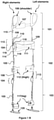
- the said apparatus comprising one or more straps/belts for waist 111, back 107 or shoulders 106; and one or more body adaptable shoulder element 101, thigh element 102, leg element 103 and a structure 601 having a body adaptable shaped profile to carry loads wherein upper side of structure is mounted at back strap 107 using moveable securing means characterized in that the structure 601 may form a platform or a cantilever beam which may transmit the load at the head to the belt and further the belt may transfer the load to the leg and finally to the ground.
- the present invention relates to an apparatus and method embodying an improved belt for body support and for assisting body during heavy lifting, kneeling, bending and walking. More particularly, the belt (referred also as apparatus at various instances in the specification) employs a single point torque adjusting mechanical assembly with an adjustable hinge along with resilient means which stores potential energy when the user alters posture from a neutral position and helps the body to return to the neutral position.
- neutral posture may be a posture where the joints are not bent and the spine and legs are aligned and are not twisted.
- load may be used interchangeably and point to similar meaning.
- resilient means may be an object which is capable to recoil or spring back into shape after bending, stretching or being compressed.
- Resilient means may comprise a spring, hydraulics pneumatics, elastic strand, elastic rope, band and the like.
- the resilient means may be powered or unpowered.
- muscleculoskeletal activities may comprise human actions further comprising kneeling, sitting, walking, running, up/down bending, bending forward/backward and left/right rotation, carrying and picking the load, and other similar activities for various durations and frequency.
- FIG. 1 a representation of the belt is illustrated in accordance with an embodiment of the present invention.
- Element at left side of user may be called as left-element and the element at the right side of user may be called as right-element.
- Each longitudinal element may be made of at least two or three sub-elements having enlargement and engagement-disengagement arrangement.
- Upper sub-element attached with shoulder may be called as Shoulder-element 101
- sub-element attached with thigh may be called as thigh-element 102
- sub-element attached with leg may be called as leg-element 103.
- Each sub-element of a longitudinal element is adjustable in size and may be connected via one or two hinge mechanism 104 connectively coupled with single point torque/load adjusting mechanical assembly 113 and having resilient means 105 or powered resilient means or both.
- Upper end of shoulder element 101 may have cushioned strap 106 and the lower end of the shoulder element 101 is connected to upper end of thigh-element 102 via hinge and single point torque adjusting mechanical assembly 104.
- the cushioned strap 106 may grip the shoulder and the shoulder element 101 together.
- Shoulder element 101 of both sides may be connected via resilient element called back strap 107.
- Upper-end of the Shoulder element 101 may have an arrangement of adjusting the length of the Shoulder-element 101 and has flexibility and size adjustment mechanism 115 to make it ergonomically comfortable.
- the mentioned hinge mechanism 104 is connectively coupled with single point torque/load adjusting mechanical assembly 113 which movably may connect the lower end of shoulder element 101 and upper end of thigh-element 102.
- the hinge mechanism comprises of a load adjusting pipe 108 moveably attached with lower end of shoulder element 101 and has button 109 mechanism to fix load adjusting pipe 108 at a particular position. Particular position of load adjusting pipe 108 determines the load and torque of the hinge mechanism.
- An inextensible and flexible element or rope 114 connects upper end of resilient means 105 or powered resilient means to the hinge-pin 110 and passes via single point 116 located at lower end of load adjusting pipe 108.
- Hinge pin 110 may be a part of hinge mechanism fixed with lower end of shoulder-elements 101 and may movably connect to shaft 118 of the hinge.
- the other end of resilient element 105 or powered resilient element may be fixed to the lower end of the thigh-element 102.
- the apparatus when the user bends down, the apparatus may generate a force of tension in inextensible and flexible elements which transfer the load to resilient means 105.
- the potential energy gets stored in resilient means 105 and the hinge mechanism 104 connectively coupled with single point torque/load adjusting mechanical assembly 113 may provide counter support to user's back and waist through the waist strap.
- the stored potential energy assists the user when user tends to bend-up and stand up.
- Different positions of mentioned load adjusting pipe 108 or different combination of r and 1 ensure the different length of lever arm of the hinge and make different elongations to resilient means 105. If load adjusting pipe 108 is positioned to increase lever arm length, then the hinge may provide more counter torque or increase the counter load resulting the hinge to bear more load and vice-versa.
- the length of flexible inextensible element or rope 114 is equivalent to sum of lengths of r (OA) and 1 (AB) and remain same for different lever arm length.
- Each of the thigh elements 102 or longitudinal element may be movably connected with the waist belt 111.
- Waist belt 111 may be cushioned flexible element meant to wrap around the waist or body of the user. It may connect both longitudinal elements at the waist together and to the waist of user.
- Lower end of thigh-element 102 has pad like structure and cushioned straps 112 that may grip the thigh-element 102 to the thigh.
- Pad like structure may be adjusted at different position at thigh-element 102 and have different ergonomics and user friendly shape and arrangement that enable to wear the belt over cloths such as Skirts and Sarees without need of straps or tying around thighs.
- the lower end of thigh-element 102 is moveably connected to the leg-element 103 via another hinge 104 cum load/torque adjusting mechanical assembly 113 similar to described hinge mechanism 104 connectively couple with single point torque/load adjusting mechanical assembly 113 at lower end of Shoulder-element 101 but later is for knee.
- Lower end of leg-element 103 may have padded and cushioned strap 117 to grip leg-elements 103 with the leg and also have foot element 120 moveably secured with the lower end of leg element 103 to transfer the load and weight to ground.
- the hinge mechanism 104 that is connectively coupled with single point torque/load adjusting mechanical assembly 113 may support and assist the knees of user. When user sits-down or when he folds the leg by using the knees then the potential energy may get stored in the resilient mean 105 or powered resilient means. The same energy supports the user and assists the user during standing-up or in musculoskeletal activities.
- a flexible and adjustable mechanism 115 may be provided above the load adjusting pipe 108 and below the shoulder element 101 to change the height of the apparatus for the concerned user. This mechanism may provide better ergonomics to the apparatus for compliance in the user-apparatus working environment.
- 502 which lies inside shoulder element 101 with springs or resilient mean, helps in size adjustment and gets compressed when user bends down and return in normal shape when user bend up to ensures shoulder element moves in accordance with shoulder.
- leg-element 103 may transfer the weight and load from the user to ground and lower part of body thus minimizing the adverse consequences of lifting heavy load and strenuous activities. Its assists the also when user is half seated, stand up, seats frequently.
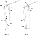
- FIG. 2 which illustrates apparatus and methods for reducing the effort using the counter torque produced by the hinge mechanism 104 connectively coupled with single point torque/load adjusting mechanical assembly 113 in accordance with an embodiment of the present subject matter.
- the upper part of the hinge mechanism 104 connectively coupled with single point torque/load adjusting mechanical assembly 113 may constitute the load adjusting pipe 108 with button 109 mechanism.
- the load adjusting pipe may have groves or holes in it to engage the button 109 as per the required load.
- Length OA denotes the lever arm which non-linearly varies the torque and counter torque in the apparatus as torque is directly proportional to lever arm and the force applied. Point O may always remain fixed.
- the load adjusting pipe 108 may slide over the lower end of shoulder element 101 to change the lever arm length.
- the stored potential energy may exert a force on load adjusting pipe at the single point A at distance AO from point O which may eventually produce torque due to the lever arm.
- a single point torque adjusting mechanical assembly 113 adjusts the torque by adjusting the lever arm (r) length such that the lower/second end D of resilient means 105 needs not to be shifted.
- the length OD and sum of lengths of 1 and r remains constant; and do not require adjusting pre load/tension in resilient means 105; and comprises of load adjusting pipe 108 and flexible inextensible element or wire rope 114 wherein load adjusting pipe has single point (A) 116 at its lower end.
- Load adjusting pipe 108 can be slide over the lower end of shoulder element 101 and thigh elements 102 to change the lever arm length to produce non-linear variable counter torque to reduce the effort for musculoskeletal actions.
- the load adjusting pipe 108 can be locked/unlocked with lower end of shoulder element 101 using engagement/disengagement button 109; and optionally comprises of extended mechanism to facilitate locking/unlocking and sliding of load adjusting pipe 108 to adjust the torque; and single point torque adjusting mechanical assembly can be used/applied in other applications such as humanoid, exo-skeletons and other applications and equipments.
- FIG. 2B a similar mechanism with alternative arrangements of the hinge with the load adjusting pipe 108 and the resilient means is illustrated in Figure 2B with an embodiment of the present subject matter. This configuration may work similar in functionality with Figure 2A but may have different orientation as shown in Figure 2 B
- an extended mechanism 301 for adjusting load is illustrated with an embodiment of the present subject matter.
- the apparatus may be equipped with an extended mechanism 301 to enable the user to adjust the torque by adjusting load pipe 108 and engage/disengage the button 109.
- the apparatus may comprise one or more extended mechanisms 301 for adjusting load for hinge 104 cum load adjusting mechanical assembly 113 at the waist and another hinge 104 cum load adjusting mechanical assembly 113 at knee for leg element103.
- the extended mechanism 301 for adjusting the load may be positioned at the front of waist or elsewhere which may be easily accessible by the user as preferred than that of position where the hinge mechanism 104 connectively coupled with single point torque/load adjusting mechanical assembly 113 is located.
- the lock mechanism may help the user to adjust the torque.
- the extended mechanism 301 for adjusting the load may comprise a lock element 302, one or more wires 303 connected to the button 109 which passes through the lock element 302 and may be attached to the load adjusting pipe 108 by fastening means, a tension spring 304 connected to a fixed support at one end and the load adjusting pipe 108 at the other end, a compression spring 305 connected to the button 109 such that the compressive force makes the button 109 to insert in the holes or slots in the load adjusting pipe 108.
- the wires 306 are meant to slide the load pipe 108 and wires 307 are meant for engaging/disengaging button 109.
- One or more wires 306, 307 may be locked at the locking element 302.
- buttons 109 and load adjusting pipe 108 can slide when user moves the knob 308 from the lock element 302.
- button 109 is locked due to compression spring 305.
- Load adjusting pipe 108 is set for minimum lever arm length due to default action of tension spring 304.
- the button 109 auto engages itself when next or previous slot arrives against it because of the compressive action of the compression spring 305.
- the tension spring 304 allows load adjusting pipe to return to the minimum position as the tension in the spring forces the load adjusting pipe 108 to come towards hinge pin 110 or toward axis/shaft 118 of rotation of hinge.
- Wires 303 corresponding to one load adjusting pipe 108 is such that it is one continuous wire 303 though it appears as two wires from the lock element 302. Each one main wire 303 may correspond to their respective left or right load adjusting pipe 108.
- a single point torque adjusting mechanical assembly wherein mechanical assembly non-linearly varies the torque by adjusting a lever arm length such that fixed end of a resilient means 105' need not be displaced; the said mechanism comprising of an upper element 101', a lower element 102', resilient means 105' with fixed end and free end 119', flexible inextensible element or rope 114', hinge pin 110' and shaft 118', load/torque adjusting means 113' having a single point at its free end 116'.
- the mechanical assembly is such that the upper element 101' is moveably secured with lower element 102' by the hinge pin 110' and shaft 118', and one end of the load adjusting means 108 is moveably connected with a secured end of upper element 101'.
- the flexible inextensible element or rope 114' is moveably secured with/between the free end 119' of the resilient means and hinge pin 110' and such flexible inextensible element 114' passes through the free end 116 of the load adjusting means 105'.
- the length of flexible inextensible element or rope 114' is equivalent or equal to sum of distance between hinge pin 110' and free end 116' of load adjusting means 108' and distance between free end 116' of load adjusting means and the free end 119' of the resilient means.
- the said load adjusting means 108' can slide over the lower end of upper element 101' to change the lever arm length to produce non-linear variable counter torque.
- Hinge pin 110' and shaft 118' can be replaced as a ball and socket joint.
- the adjustment of pre load/tension in resilient means 105' is not required in this mechanism.
- the load adjusting means 105' can be locked/unlocked with lower end of upper element 101' using engagement/disengagement means 109'.
- the mechanism optionally comprises of extended mechanism to facilitate locking/unlocking and sliding of load adjusting means 108' to adjust the torque.
- FIG. 5 various positions of the apparatus with element showing exploded view and assembled view wherein the load transfer from the apparatus to the ground by enabling a foot element 120 is illustrated with an embodiment of the present subject matter.
- the working of the belt is illustrated at various positions with an embodiment of the present subject matter.
- Figure 1-A an exploded view of the apparatus is represented wherein from the top to the bottom all elements comprising the shoulder element 101, load adjusting pipe 108, button 109, rope 114, hinge 104, resilient means 105, the lower hinge and resilient means and the foot element 120 for transferring the load at the ground.
- the assembled apparatus is represented at neutral position with no bending or twisting of any joints or muscles by the user (not shown).
- the hinges which may be at neutral position or posture may be at zero-degree bend and resilient means 105 may also be in an unloaded position.
- Figure 4-C the assembled belt is represented along with a sitting posture.
- the extended leg element 103 may have the foot element 120 which may transfer the load from the body to the leg element 103 and finally to the ground.
- all the hinges at the waist and the knees and all the resilient means 105 are into action to overcome the load acting on the user.
- FIG. 6 an addition of structure 601 to carry loads which may be pivoted at pivot points 602 mechanical element connecting both 3D or simple hinges 603 and upper side of structure is mounted at back strap 107 is illustrated with an embodiment of the present subject matter.
- the apparatus may also be equipped by a load carrying structure which may be attached to the back of the apparatus near at mechanical element connecting both 3D hinges 603 and uppers side of structure is mounted at back strap 107.
- the 3D hinges 603 are mounted on lower end (inner pipe) of shoulder element.
- the structure 601 may be a continuous Z shaped profile if viewed from the left side of the user.
- the upper part of the structure 601 may be used to carry load at the head.
- the upper part of the structure 601 may form a platform or a cantilever beam which may transmit and share the load at the head to the belt and further the belt may transfer the load to the leg and finally to the ground.
- the load may also be carried at the back with help of the lower platform which may also work as a load carrying beam.
- the load on the lower part may be transferred to the apparatus by the insertion of the pivot which may join the structure 601 and the apparatus at the pivot point. Heavy lifting of loads comprising sack of grains, cement or any other material may be performed with ease by the apparatus attached with the structure 601.
- Pivoted at mechanical element connecting both 3d hinges 603 and uppers side of structure is mounted at back strap 107.
- the 3D hinges 603 are mounted on lower end (inner pipe) of shoulder element.
- the attachment of the structure 601 may be so adjusted that the orientation of the structure remains vertical.
- the structure 601 may be pivoted at pivot points 602 at mechanical element connecting both 3D hinges 603 and uppers side of structure is mounted at back strap 107.
- the 3D hinges 603 are mounted on lower end (inner pipe) of shoulder element which may enable swivelling of the structure in multi direction when user performs actions comprising flexion, bending, bending with rotation or unlevelled stepping.
- the incorporation of the multidirectional joints 601 results in the correct vertical orientation of the structure even if user' posture may not be vertical.
- Table 1 represents a data of a user with 70 kg self-weight with height 180 cm and lifting a load of 20 kg with lever arm of 1 cm.
- Table 1 Sr. No. Angle ° (degrees) Load (N-cm) on User's waist without wearing apparatus Assistive Torque provided by Apparatus Reduced Load (N-cm) on User's waist after wearing apparatus.
- r(OA) 1 1 0 0 0 0 2 30 865 6 859 3 60 1499 37 1462 4 90 1731 83 1648 5 120 1499 103 1396 6 150 866 72 793 7 180 0 0 0
- Table 4 represents a data of a user with 70 kg self-weight with height 180 cm and lifting a load of 20 kg with lever arm of 4 cm.
- Table 4 Sr. No. Angle ° (degrees) Load (N-cm) on User's waist without wearing apparatus+ Assistive Torque provided by Apparatus Reduced Load (N-cm) on User's waist after wearing apparatus.
- the maximum torque may be obtained at lever arm 4 cm which may provide a maximum arm length thus resulting in a maximum torque.
- a maximum torque at each lever arm length may be observed at angle 80-110 degrees.
Landscapes
- Health & Medical Sciences (AREA)
- Animal Behavior & Ethology (AREA)
- Veterinary Medicine (AREA)
- Public Health (AREA)
- General Health & Medical Sciences (AREA)
- Life Sciences & Earth Sciences (AREA)
- Engineering & Computer Science (AREA)
- Rehabilitation Therapy (AREA)
- Physical Education & Sports Medicine (AREA)
- Pain & Pain Management (AREA)
- Epidemiology (AREA)
- Textile Engineering (AREA)
- Nursing (AREA)
- Orthopedic Medicine & Surgery (AREA)
- Biomedical Technology (AREA)
- Heart & Thoracic Surgery (AREA)
- Vascular Medicine (AREA)
- Mechanical Engineering (AREA)
- Robotics (AREA)
- Rehabilitation Tools (AREA)
- Orthopedics, Nursing, And Contraception (AREA)
- Manipulator (AREA)
Description
- The present invention relates to a single point load/torque adjusting mechanical assembly. More particularly, the invention pertains to an assembly to reduce human effort, assist knees and waist in order to share such load from head, back, spine, waist and knees and transfer load to ground.
- The framework of human body is composed of many bones, tendons and ligaments joined together to produce a perfect frame. Spine is very vital part of the human body whose function comprises body support, support for head, movement, protection of spinal cord, co-ordination and control. Support for head is paramount because the neck is involved in quick coordinating movements for general daily activities. Protection of spinal cord from jerks, shocks and strains is crucial in maintaining whole body health.
- In addition to the healthy spinal cord, all body joints along with ligaments and tendons are required to be in good condition to maintain proper posture, effective movement or locomotion.
- People involved in activities like regular lifting or carrying of weight, carrying weight over head or back, or doing other similar hardships are exposed to frequent bending and retracting of the body parts that may result in disorders comprising waist pain, knee pain, neck pain, vertebral dislocation and the like due to straining and stretching of body parts. Constant laborious work with too much bending, kneeling and walking may lead also lead to disorders like spondylitis, kyphosis or inflammation. Some people may also acquire osteoporotic spine which changes the shape of the spine itself.
- Such disorders are treated by use of high doses of pain killers or by employment of fixed web structures, elastic belts which are usually wrapped around the susceptible body parts. It is often the strategy to support spine and waist by tying up straps around them; however, this may restrict the body motion partly or wholly. Such a solution may also not assist spine or waist completely.
- Thus there exists a long felt need for a solution which not only assists the person in lifting heavy objects but also supports his bent position, sitting posture, carrying load over back and head, long distance walking and can be used as corrective measure for spinal disorders like spondylitis, kyphosis and inflammation.
- In a prior art a Patent application number
US20080154165 proposes mainly body weight support device with a floor contact member. This externally powered and legs centric device is very heavy due to the presence of actuator, drive units and other auxiliary components. The Indian Patent application number 2155/DEL/2008 filed by the inventor of this patent itself proposes a belt that does not have attachable members like leg apparatus, structure for sharing load from head, waist, back to ground, single point torque adjustment mechanical assembly. Another prior art patentUS6041444 proposes load supporting waist belt for supporting the weight of the user himself, however the disclosed belt does not assist walking or reducing the total or partial load being carried or displaced by user.US4632096 proposes same function but only for bracing or supporting knees. The invention disclosed inUS5147261 may help in lifting by constraining the lumbar region by a flexible belt with no other unique mechanism. The device disclosed inUS6016869 is a pedalling, heavy and bulky device for lift assisting.DE102004008509A1 describes a shoulder element which is releasably secured to the shoulder by a fixer and a hip element in the shape of a C-bow partly encircles the pelvis in the posterior area and is operably connected (3) to a chest element. A leg element (4) in lever shape makes contact with the user's thigh and is joined at the second lever end (4) to the hip element pivotally round axis (A). The leg element (4) is pre-tensioned round axis (A) by a spring with pre-set moment and the aid components in conjunction ensure that counter-moment applied to the leg is transmitted without loss by the transmitter component (5), hip element and connections (3) to the shoulder element which in turn transfers an erecting moment to the upper body. The shoulder element includes two shoulder stirrups and/or closable belt, the connectors (3) to be a back plate adapted to the ergonomy of the person's spine. - The above mentioned prior inventions in this domain have not disclosed a lightweight apparatus with single point assisting torque adjustment mechanism, which is self-powered, light weight, compact yet efficient, simple and user friendly apparatus which not only assists the person in lifting heavy objects but also supports his kneeling position, bent position, lateral bending, sitting posture, carrying load overhead, back, long distance walking and can be used as corrective measure for spinal disorders like spondylitis, kyphosis or inflammation and easy to be worn by a user and is effective in reducing the effort of the human body to carry out various voluntary muscular action with full freedom of movement of the body parts.
- The present invention comprises a single point load/torque adjusting mechanical assembly according to
claim 1, a method according to claim 5 for employing such a single point load/torque adjusting mechanical assembly, an apparatus for assisting musculoskeletal activities according to claim 6, and a leg apparatus for assisting musculoskeletal activities according to claim 12. - Before the present apparatus and its components and its method of use is described, it is to be understood that this disclosure is not limited to the particular apparatus and its arrangement as described, as there can be multiple possible embodiments which are not expressly illustrated in the present disclosure but may still be practicable within the scope of the invention as determined by claims. It is also to be understood that the terminology used in the description is for the purpose of describing the particular versions or embodiments only, and is not intended to limit the scope of the present application. This summary is not intended to identify essential features of the claimed subject matter nor is it intended for use in detecting or limiting the scope of the claimed subject matter.
- In one aspect there is described a single point torque adjusting mechanical assembly wherein mechanical assembly varies the torque non linearly by adjusting a lever arm length such that fixed end of a resilient means need not be displaced; the said mechanical assembly comprising of an upper element, a lower element, resilient means with fixed end and free end, flexible inextensible element or rope, hinge pin and shaft, load/torque adjusting means having a single point at its free end. The mechanical assembly is such that the upper element is moveably secured with lower element by the hinge pin and shaft, and one end of the load adjusting means is moveably connected with a secured end of upper element. The flexible inextensible element or rope is moveably secured with/between the free end of the resilient means and hinge pin and such flexible inextensible element passes through the free end of the load adjusting means. The length of flexible inextensible element or rope is equivalent or equal to sum of distance between hinge pin and free end of load adjusting means and distance between free end of load adjusting means and the free end of the resilient means. The sum of such distance remains constant.
- In another aspect, there is described an apparatus for assisting musculoskeletal activities wherein the apparatus enables a user to overcome the effort required to return to a neutral position by employing a counter torque, by storing potential energy in a resilient means. The apparatus comprises one or more longitudinal mechanical elements, an adjustable hinge mechanism means; one or more resilient means; an arrangement for height and torque load adjustment means; and one or more straps for waist, back or shoulders as well as a thigh element moveably and flexibly connected to straps. The apparatus as a whole is characterized by single point torque adjusting mechanical assembly so that the counter torque is developed when the user alters the body posture from the neutral position by performing musculoskeletal activities which results in the potential energy being stored in the resilient means. The single point torque adjusting mechanical assembly incorporated with adjustable hinge attached to a resilient means is responsible for generating a counter torque to bring back the user to the neutral position. The counter torque can be non-linearly varied using single point torque adjusting mechanical assembly for adjusting distance between hinge and a single point, wherein the hinge acts as an axis of rotation and said longitudinal distance acts as lever arm. The single point torque adjusting mechanical assembly incorporated with adjustable hinge are used for spine, pelvic and knee joints and has extended arrangements to use the single point torque adjusting mechanical assembly. In another aspect the apparatus also has attachable structure to share the load from head, spine and back in order to transfer the shared load to waist and ground. Thus transferring the load on head and back to the ground.
- In yet another aspect there is described a method for assisting musculoskeletal activities using an apparatus wherein the apparatus enables a user to overcome the effort required to return to a neutral position by employing a counter torque by storing potential energy in a resilient means. The method as a whole may be performed in a manner that the counter torque is developed when the user alters the body posture from the neutral position by performing musculoskeletal activities which results in the potential energy being stored in the resilient means. The single point torque adjusting mechanical assembly incorporated with adjustable hinge attached to a resilient means are responsible for generating a counter torque to bring back the user to the neutral position. The counter torque can be non-linearly varied using single point torque adjusting mechanical assembly by adjusting distance between hinge and single point, wherein the hinge acts as an axis of rotation and said longitudinal distance acts as lever arm. The single point torque adjusting mechanical assembly incorporated with adjustable hinge are used for pelvic and knee joints and has extended arrangements to use the single point torque adjusting mechanical assembly. Apparatus also has attachable structure to share the load from head, spine and back in order to transfer the shared load to waist and ground. Thus transferring the load on head and back to the ground.
- In yet another aspect there is described an apparatus for assisting musculoskeletal activities wherein the apparatus enables a user to share load on body parts and transfer such load to the ground, the said apparatus comprising one or more straps/belts for
waist 111,back 107 orshoulders 106; and one or more bodyadaptable shoulder element 101,thigh element 102,leg element 103 and astructure 601 having a body adaptable shaped profile to carry loads wherein upper side of structure is mounted atback strap 107 using moveable securing means characterized in that thestructure 601 may form a platform or a cantilever beam which may transmit the load at the head to the belt and further the belt may transfer the load to the leg and finally to the ground. - The detailed description is described with reference to the accompanying Figures. In the Figures, the left-most digit(s) of a reference number identifies the Figure in which the reference number first appears. The same numbers are used throughout the drawings to refer like features and components.
-
Figure 1A illustrates a representation of the apparatus belt in accordance with an embodiment of the present subject matter. -
Figure 1B illustrates a representation of the apparatus belt with an attachable leg apparatus/element. -
Figure 2 illustrates a method for reducing the effort using the counter torque produced by thehinge mechanism 104 connectively coupled with single point torque/load adjustingmechanical assembly 113 in accordance with an embodiment of the present subject matter. -
Figure 3 illustrates an extended mechanism for adjusting load mechanism with an embodiment of the present subject matter. -
Figure 4 illustrates a single point torque/load adjusting mechanical assembly with an embodiment of the present subject matter. -
Figure 5 illustrates various positions of the apparatus with element showing exploded view and assembled view wherein the load transfer from the apparatus to the ground by enabling afoot element 120 with an embodiment of the present subject matter. -
Figure 6 illustrates an additional structure to carry loads which may be movably secured at the waist and back by belts with an embodiment of the present subject matter. -
Figure 7 illustrates results for torque and load when a user incorporates the apparatus withlever arm length 1 cm in accordance with an embodiment of the present subject matter. -
Figure 8 illustrates results for torque and load when a user incorporates the apparatus with lever arm length 2 cm in accordance with an embodiment of the present subject matter. -
Figure 9 illustrates results for torque and load when a user incorporates the apparatus with lever arm length 3 cm in accordance with an embodiment of the present subject matter. -
Figure 10 illustrates results for torque and load when a user incorporates the apparatus withlever arm length 4 cm in accordance with an embodiment of the present subject matter. - The present invention relates to an apparatus and method embodying an improved belt for body support and for assisting body during heavy lifting, kneeling, bending and walking. More particularly, the belt (referred also as apparatus at various instances in the specification) employs a single point torque adjusting mechanical assembly with an adjustable hinge along with resilient means which stores potential energy when the user alters posture from a neutral position and helps the body to return to the neutral position.
- For the purpose of this invention "neutral posture" may be a posture where the joints are not bent and the spine and legs are aligned and are not twisted. The words "load", "torque" and "assisting torque" are used interchangeably and point to similar meaning.
- For the purpose of this invention "resilient means" may be an object which is capable to recoil or spring back into shape after bending, stretching or being compressed. Resilient means may comprise a spring, hydraulics pneumatics, elastic strand, elastic rope, band and the like. In one embodiment of the invention the resilient means may be powered or unpowered.
- For the purpose of this invention "musculoskeletal activities" may comprise human actions further comprising kneeling, sitting, walking, running, up/down bending, bending forward/backward and left/right rotation, carrying and picking the load, and other similar activities for various durations and frequency.
- For the purpose of the invention the words System and Apparatus are also interchangeably used.
- For the purpose of this invention, all results in tables, graphs or numbers comprising torque, load, angles in degrees, length and the like included are to be considered in the range of ± 10 % of the given value. For example, a torque of 100 N-cm should be considered in the range of 90 N-cm to 110 N-cm. It is to be understood that graphical or numerical data is based on a prototype developed with particular set of embodiments and arrangements as described, but does not limit the apparatus and method as there can be multiple possible embodiments, settings and arrangements which are not expressly illustrated in the present disclosure.
- Referring to
Figure 1 , a representation of the belt is illustrated in accordance with an embodiment of the present invention. Element at left side of user may be called as left-element and the element at the right side of user may be called as right-element. Each longitudinal element may be made of at least two or three sub-elements having enlargement and engagement-disengagement arrangement. Upper sub-element attached with shoulder may be called as Shoulder-element 101, sub-element attached with thigh may be called as thigh-element 102 and sub-element attached with leg may be called as leg-element 103. Each sub-element of a longitudinal element is adjustable in size and may be connected via one or twohinge mechanism 104 connectively coupled with single point torque/load adjustingmechanical assembly 113 and havingresilient means 105 or powered resilient means or both. Upper end ofshoulder element 101 may have cushionedstrap 106 and the lower end of theshoulder element 101 is connected to upper end of thigh-element 102 via hinge and single point torque adjustingmechanical assembly 104. The cushionedstrap 106 may grip the shoulder and theshoulder element 101 together.Shoulder element 101 of both sides may be connected via resilient element called backstrap 107. Upper-end of theShoulder element 101 may have an arrangement of adjusting the length of the Shoulder-element 101 and has flexibility andsize adjustment mechanism 115 to make it ergonomically comfortable. The mentionedhinge mechanism 104 is connectively coupled with single point torque/load adjustingmechanical assembly 113 which movably may connect the lower end ofshoulder element 101 and upper end of thigh-element 102. - The hinge mechanism comprises of a
load adjusting pipe 108 moveably attached with lower end ofshoulder element 101 and hasbutton 109 mechanism to fixload adjusting pipe 108 at a particular position. Particular position ofload adjusting pipe 108 determines the load and torque of the hinge mechanism. An inextensible and flexible element orrope 114 connects upper end ofresilient means 105 or powered resilient means to the hinge-pin 110 and passes viasingle point 116 located at lower end ofload adjusting pipe 108.Hinge pin 110 may be a part of hinge mechanism fixed with lower end of shoulder-elements 101 and may movably connect toshaft 118 of the hinge. The other end ofresilient element 105 or powered resilient element may be fixed to the lower end of the thigh-element 102. - In an embodiment, when the user bends down, the apparatus may generate a force of tension in inextensible and flexible elements which transfer the load to
resilient means 105. Thus the potential energy gets stored inresilient means 105 and thehinge mechanism 104 connectively coupled with single point torque/load adjustingmechanical assembly 113 may provide counter support to user's back and waist through the waist strap. The stored potential energy assists the user when user tends to bend-up and stand up. Different positions of mentionedload adjusting pipe 108 or different combination of r and 1 ensure the different length of lever arm of the hinge and make different elongations toresilient means 105. Ifload adjusting pipe 108 is positioned to increase lever arm length, then the hinge may provide more counter torque or increase the counter load resulting the hinge to bear more load and vice-versa. The length of flexible inextensible element orrope 114 is equivalent to sum of lengths of r (OA) and 1 (AB) and remain same for different lever arm length. Each of thethigh elements 102 or longitudinal element may be movably connected with thewaist belt 111.Waist belt 111 may be cushioned flexible element meant to wrap around the waist or body of the user. It may connect both longitudinal elements at the waist together and to the waist of user. Lower end of thigh-element 102 has pad like structure and cushionedstraps 112 that may grip the thigh-element 102 to the thigh. Pad like structure may be adjusted at different position at thigh-element 102 and have different ergonomics and user friendly shape and arrangement that enable to wear the belt over cloths such as Skirts and Sarees without need of straps or tying around thighs. The lower end of thigh-element 102 is moveably connected to the leg-element 103 via anotherhinge 104 cum load/torque adjustingmechanical assembly 113 similar to describedhinge mechanism 104 connectively couple with single point torque/load adjustingmechanical assembly 113 at lower end of Shoulder-element 101 but later is for knee. Lower end of leg-element 103 may have padded and cushionedstrap 117 to grip leg-elements 103 with the leg and also havefoot element 120 moveably secured with the lower end ofleg element 103 to transfer the load and weight to ground. Thehinge mechanism 104 that is connectively coupled with single point torque/load adjustingmechanical assembly 113 may support and assist the knees of user. When user sits-down or when he folds the leg by using the knees then the potential energy may get stored in theresilient mean 105 or powered resilient means. The same energy supports the user and assists the user during standing-up or in musculoskeletal activities. - In an implementation, a flexible and
adjustable mechanism 115 may be provided above theload adjusting pipe 108 and below theshoulder element 101 to change the height of the apparatus for the concerned user. This mechanism may provide better ergonomics to the apparatus for compliance in the user-apparatus working environment. In anotherembodiment 502 which lies insideshoulder element 101 with springs or resilient mean, helps in size adjustment and gets compressed when user bends down and return in normal shape when user bend up to ensures shoulder element moves in accordance with shoulder. - Referring
figure 1 B , the assembly along with the leg element or leg apparatus is illustrated with an embodiment of the present invention. In another embodiment, a mechanism that may also ensure the movement of leg-element 103 during walking and sitting posture of user is disclosed. This mechanism may have elements connecting shoulder-element 101 to leg-element 103. The leg-element 103 may transfer the weight and load from the user to ground and lower part of body thus minimizing the adverse consequences of lifting heavy load and strenuous activities. Its assists the also when user is half seated, stand up, seats frequently. - In case of a person who is wearing the belt system of the current invention, when such person bends up/down, sits down or stands up while lifting a weight or while such person is doing any other strenuous activity, the strain and stress falling on body part of such person is taken up by the elastic force provided in
resilient means 105 resulting in free movement of his back, waist and knee, without running the risk of adverse consequences. - Referring to
Figure 2 , which illustrates apparatus and methods for reducing the effort using the counter torque produced by thehinge mechanism 104 connectively coupled with single point torque/load adjustingmechanical assembly 113 in accordance with an embodiment of the present subject matter. In an implementation, the upper part of thehinge mechanism 104 connectively coupled with single point torque/load adjustingmechanical assembly 113 may constitute theload adjusting pipe 108 withbutton 109 mechanism. The load adjusting pipe may have groves or holes in it to engage thebutton 109 as per the required load. Length OA denotes the lever arm which non-linearly varies the torque and counter torque in the apparatus as torque is directly proportional to lever arm and the force applied. Point O may always remain fixed. Theload adjusting pipe 108 may slide over the lower end ofshoulder element 101 to change the lever arm length. A flexible inextensible element of length equivalent to sum of AO and AB, passing via single point A, connects Point O of hinge to the upper end B ofresilient means 105 or power resilient means which may store the potential energy when the user bends down, kneels down or takes a sitting posture. The stored potential energy may exert a force on load adjusting pipe at the single point A at distance AO from point O which may eventually produce torque due to the lever arm. A single point torque adjustingmechanical assembly 113 adjusts the torque by adjusting the lever arm (r) length such that the lower/second end D ofresilient means 105 needs not to be shifted. The length OD and sum of lengths of 1 and r remains constant; and do not require adjusting pre load/tension inresilient means 105; and comprises ofload adjusting pipe 108 and flexible inextensible element orwire rope 114 wherein load adjusting pipe has single point (A) 116 at its lower end. Flexible inextensible element orwire rope 114 of length (1+r) connected to upper end of resilient mean 105 to hinge pin via single point (A) ofload adjusting pipe 108.Load adjusting pipe 108 can be slide over the lower end ofshoulder element 101 andthigh elements 102 to change the lever arm length to produce non-linear variable counter torque to reduce the effort for musculoskeletal actions. Theload adjusting pipe 108 can be locked/unlocked with lower end ofshoulder element 101 using engagement/disengagement button 109; and optionally comprises of extended mechanism to facilitate locking/unlocking and sliding ofload adjusting pipe 108 to adjust the torque; and single point torque adjusting mechanical assembly can be used/applied in other applications such as humanoid, exo-skeletons and other applications and equipments. - In an embodiment, a similar mechanism with alternative arrangements of the hinge with the
load adjusting pipe 108 and the resilient means is illustrated inFigure 2B with an embodiment of the present subject matter. This configuration may work similar in functionality withFigure 2A but may have different orientation as shown inFigure 2 B - Referring
Figure 3 , anextended mechanism 301 for adjusting load is illustrated with an embodiment of the present subject matter. In an embodiment, the apparatus may be equipped with anextended mechanism 301 to enable the user to adjust the torque by adjustingload pipe 108 and engage/disengage thebutton 109. The apparatus may comprise one or moreextended mechanisms 301 for adjusting load forhinge 104 cum load adjustingmechanical assembly 113 at the waist and anotherhinge 104 cum load adjustingmechanical assembly 113 at knee for leg element103. Theextended mechanism 301 for adjusting the load may be positioned at the front of waist or elsewhere which may be easily accessible by the user as preferred than that of position where thehinge mechanism 104 connectively coupled with single point torque/load adjustingmechanical assembly 113 is located. The lock mechanism may help the user to adjust the torque. - In an embodiment, the
extended mechanism 301 for adjusting the load may comprise alock element 302, one ormore wires 303 connected to thebutton 109 which passes through thelock element 302 and may be attached to theload adjusting pipe 108 by fastening means, atension spring 304 connected to a fixed support at one end and theload adjusting pipe 108 at the other end, acompression spring 305 connected to thebutton 109 such that the compressive force makes thebutton 109 to insert in the holes or slots in theload adjusting pipe 108. Thewires 306 are meant to slide theload pipe 108 andwires 307 are meant for engaging/disengaging button 109. One ormore wires locking element 302. In an implementation, when the user pulls thewire 307 by pressingknob 308, it unlocks thebutton 109 and load adjustingpipe 108 can slide when user moves theknob 308 from thelock element 302. Indefault condition button 109 is locked due tocompression spring 305.Load adjusting pipe 108 is set for minimum lever arm length due to default action oftension spring 304. Thebutton 109 auto engages itself when next or previous slot arrives against it because of the compressive action of thecompression spring 305. Thetension spring 304 allows load adjusting pipe to return to the minimum position as the tension in the spring forces theload adjusting pipe 108 to come towardshinge pin 110 or toward axis/shaft 118 of rotation of hinge. Thus by theextended mechanism 301 for adjusting the load, the user may adjust the torque and load carrying capacity of the apparatus easily.Wires 303 corresponding to oneload adjusting pipe 108 is such that it is onecontinuous wire 303 though it appears as two wires from thelock element 302. Each onemain wire 303 may correspond to their respective left or rightload adjusting pipe 108. - Referring
Fig 4 , a representation the single point torque/load adjusting mechanical assembly is illustrated with an embodiment of the present invention. A single point torque adjusting mechanical assembly wherein mechanical assembly non-linearly varies the torque by adjusting a lever arm length such that fixed end of a resilient means 105' need not be displaced; the said mechanism comprising of an upper element 101', a lower element 102', resilient means 105' with fixed end and free end 119', flexible inextensible element or rope 114', hinge pin 110' and shaft 118', load/torque adjusting means 113' having a single point at its free end 116'. The mechanical assembly is such that the upper element 101' is moveably secured with lower element 102' by the hinge pin 110' and shaft 118', and one end of the load adjusting means 108 is moveably connected with a secured end of upper element 101'. The flexible inextensible element or rope 114' is moveably secured with/between the free end 119' of the resilient means and hinge pin 110' and such flexible inextensible element 114' passes through thefree end 116 of the load adjusting means 105'. The length of flexible inextensible element or rope 114' is equivalent or equal to sum of distance between hinge pin 110' and free end 116' of load adjusting means 108' and distance between free end 116' of load adjusting means and the free end 119' of the resilient means. The sum of such distance remains constant. The said load adjusting means 108' can slide over the lower end of upper element 101' to change the lever arm length to produce non-linear variable counter torque. Hinge pin 110' and shaft 118' can be replaced as a ball and socket joint. The adjustment of pre load/tension in resilient means 105' is not required in this mechanism. The load adjusting means 105' can be locked/unlocked with lower end of upper element 101' using engagement/disengagement means 109'. The mechanism optionally comprises of extended mechanism to facilitate locking/unlocking and sliding of load adjusting means 108' to adjust the torque. - Referring
Figure 5 , various positions of the apparatus with element showing exploded view and assembled view wherein the load transfer from the apparatus to the ground by enabling afoot element 120 is illustrated with an embodiment of the present subject matter. In an embodiment, the working of the belt is illustrated at various positions with an embodiment of the present subject matter. InFigure 1-A , an exploded view of the apparatus is represented wherein from the top to the bottom all elements comprising theshoulder element 101, load adjustingpipe 108,button 109,rope 114, hinge 104, resilient means 105, the lower hinge and resilient means and thefoot element 120 for transferring the load at the ground. InFigure 1-B , the assembled apparatus is represented at neutral position with no bending or twisting of any joints or muscles by the user (not shown). The hinges which may be at neutral position or posture may be at zero-degree bend andresilient means 105 may also be in an unloaded position. In Figure 4-C, the assembled belt is represented along with a sitting posture. Theextended leg element 103 may have thefoot element 120 which may transfer the load from the body to theleg element 103 and finally to the ground. During this extreme position all the hinges at the waist and the knees and all the resilient means 105 are into action to overcome the load acting on the user. - Referring
Figure 6 , an addition ofstructure 601 to carry loads which may be pivoted at pivot points 602 mechanical element connecting both 3D orsimple hinges 603 and upper side of structure is mounted atback strap 107 is illustrated with an embodiment of the present subject matter. In another embodiment, the apparatus may also be equipped by a load carrying structure which may be attached to the back of the apparatus near at mechanical element connecting both 3D hinges 603 and uppers side of structure is mounted atback strap 107. The 3D hinges 603 are mounted on lower end (inner pipe) of shoulder element. Thestructure 601 may be a continuous Z shaped profile if viewed from the left side of the user. The upper part of thestructure 601 may be used to carry load at the head. The upper part of thestructure 601 may form a platform or a cantilever beam which may transmit and share the load at the head to the belt and further the belt may transfer the load to the leg and finally to the ground. In an implementation, the load may also be carried at the back with help of the lower platform which may also work as a load carrying beam. The load on the lower part may be transferred to the apparatus by the insertion of the pivot which may join thestructure 601 and the apparatus at the pivot point. Heavy lifting of loads comprising sack of grains, cement or any other material may be performed with ease by the apparatus attached with thestructure 601. Pivoted at mechanical element connecting both 3d hinges 603 and uppers side of structure is mounted atback strap 107. The 3D hinges 603 are mounted on lower end (inner pipe) of shoulder element. - In an implementation, the attachment of the
structure 601 may be so adjusted that the orientation of the structure remains vertical. Thestructure 601 may be pivoted at pivot points 602 at mechanical element connecting both 3D hinges 603 and uppers side of structure is mounted atback strap 107. The 3D hinges 603 are mounted on lower end (inner pipe) of shoulder element which may enable swivelling of the structure in multi direction when user performs actions comprising flexion, bending, bending with rotation or unlevelled stepping. When user steps up or down the orientation of thestructure 601 remains same due to the effect of the 3D hinge or multi directional joint 603. Thus the incorporation of themultidirectional joints 601 results in the correct vertical orientation of the structure even if user' posture may not be vertical. - Referring to
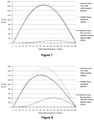
Figure 7 , a representation of non-linear variation of torque with respect to the angle of bend is illustrated and a reduction of load on user's waist is represented with torque on abscissa and angle of bend on ordinate is illustrated as an embodiment of the present subject matter. Following Table 1 represents a data of a user with 70 kg self-weight withheight 180 cm and lifting a load of 20 kg with lever arm of 1 cm.Table 1 Sr. No. Angle ° (degrees) Load (N-cm) on User's waist without wearing apparatus Assistive Torque provided by Apparatus Reduced Load (N-cm) on User's waist after wearing apparatus. When r(OA)=1 1 0 0 0 0 2 30 865 6 859 3 60 1499 37 1462 4 90 1731 83 1648 5 120 1499 103 1396 6 150 866 72 793 7 180 0 0 0 - Referring to
Figure 8 , wherein a representation of non-linear variation of torque with respect to the angle of bend and a reduction of load on user's waist is represented with torque on abscissa and angle of bend on ordinate is illustrated as an embodiment of the present subject matter. Following Table 2 represents a data of a user with 70 kg self-weight withheight 180 cm and lifting a load of 20 kg with lever arm of 2 cm.Table 2 Sr. No. Angle ° (degrees) Load (N-cm) on User's waist without wearing apparatus Assistive Torque provided by Apparatus Reduced Load (N-cm) on User's waist after wearing apparatus. When r(OA)=2 1 0 0 0 0 2 30 865 26 839 3 60 1499 160 1339 4 90 1731 340 1391 5 120 1499 405 1094 6 150 866 27 592 7 180 0 0 0 - Referring to
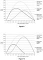
Figure 9 , wherein a representation of non-linear variation of torque with respect to the angle of bend and a reduction of load on user's waist is represented with torque on abscissa and angle of bend on ordinate is illustrated as an embodiment of the present subject matter. Following Table 3 represents a data of a user with 70 kg self-weight withheight 180 cm and lifting a load of 20 kg with lever arm of 3 cm.Table 3 Sr. No. Angle ° (degrees) Load (N-cm) on User's waist without wearing apparatus Assistive Torque provided by Apparatus Reduced Load (N-cm) on User's waist after wearing apparatus. When r(OA)=3 1 0 0 0 0 2 30 865 65 800 3 60 1499 382 1117 4 90 1731 773 958 5 120 1499 884 615 6 150 866 581 284 7 180 0 0 0 - Referring to
Figure 10 , wherein a representation of non-linear variation of torque with respect to the angle of bend is illustrated and a reduction of load on user's waist is represented with torque on abscissa and angle of bend on ordinate is illustrated as an embodiment of the present subject matter. Following Table 4 represents a data of a user with 70 kg self-weight withheight 180 cm and lifting a load of 20 kg with lever arm of 4 cm.Table 4 Sr. No. Angle ° (degrees) Load (N-cm) on User's waist without wearing apparatus+ Assistive Torque provided by Apparatus Reduced Load (N-cm) on User's waist after wearing apparatus. When r(OA)=4 1 0 0 0.00 0 2 30 865 126 739 3 60 1499 713 786 4 90 1731 1377 354 5 120 1499 1511 -12 6 150 866 967 -101 7 180 0 0 -0 - In an implementation, after observing the above data from Table 1 to Table 4, it may be concluded that the maximum torque may be obtained at
lever arm 4 cm which may provide a maximum arm length thus resulting in a maximum torque. In addition to the maximum torque, a maximum torque at each lever arm length may be observed at angle 80-110 degrees. - In an exemplary embodiment of the invention the apparatus may be employed in the fields or situations comprising:
- 1) Defence forces in which the soldiers in the army are subjected to constant running, bending, crawling and sometimes in an extraordinary uncomfortable position;
- 2) Construction sites wherein the labourers and technicians are in activities comprising bending and retracting while carrying heavy loads and other positions like drilling at extreme low or high positions, hammering and the like;
- 3) Person who is responsible for the household work such as a home-maker who performs all tasks in which many musculoskeletal activities like bending, kneeling, and the like;
- 4) All kinds of industries wherein the workers have to carry heavy loads like work piece or work jobs on machines like lathe, drilling and milling;
- 5) Old age people whose bone are degraded by low calcium content and thus require support for walking, bending, sitting down, standing up;
- 6) In agriculture wherein the farmers have to constantly bend down for piercing seeds in the ground and carrying heavy loads for storage in warehouse;
- 7) In medical fields in which patients with kyphosis, spondylitis and other similar disorder where they find uncomfortable to bend and sit.
- The present invention can be embodied in many other forms or carried out in other ways, without departing from the scope of the appended claims, and the above mentioned embodiment of the invention have been disclosed in detail only for illustrative purposes.
Claims (12)
- A single point load/torque adjusting mechanical assembly (113) wherein the said single point load/torque adjusting mechanical assembly (113) varies the torque non linearly by adjusting a lever arm length such that fixed end of a resilient means (105') need not be displaced; the said single point load/torque adjusting mechanical assembly (113) comprising:an upper element (101');a lower element (102');resilient means (105') with fixed end and free end (119'), wherein the fixed end is fixed to the lower element (102);a flexible inextensible element or rope (114');a hinge pin (110') and a shaft (118'); aload/torque adjusting means (113') having a single point (116') at its free end;wherein the upper element (101') is moveably secured with the lower element (102') by the hinge pin (110') and the shaft (118'), and one end of a load adjusting means (108') of the load/torque adjusting means (113') is moveably connected with a secured end of the upper element (101'); andthe flexible inextensible element or rope (114') is moveably secured with/between the free end (119') of the resilient means (105') and the hinge pin (110') and passes through the free end single point (116') of the load adjusting means (108');wherein the length of the flexible inextensible element or rope (114') is equivalent or equal to the sum of the distance between the hinge pin (110') and the free end single point (116') of the load adjusting means (108') and the distance between the free end single point (116') of the load adjusting means (108') and the free end (119') of the resilient means (105'), wherein said sum remains constant;and wherein said load adjusting means (108') can slide over the lower end of the upper element (101') to change the lever arm length to produce non-linear variable counter torque.
- A single point load/torque adjusting mechanical assembly (113) as claimed in claim 1 wherein adjustment of pre load/tension in the resilient means (105') is not required to adjust the torque.
- A single point load/torque adjusting mechanical assembly (113) as claimed in claim 1, wherein the load adjusting means (108') can be locked/unlocked with the lower end of upper element (101') using engagement/disengagement means (109').
- A single point load/torque adjusting mechanical assembly (113) as claimed in claim 1 wherein the mechanism optionally comprises an extended mechanism to facilitate locking/unlocking and sliding of the load adjusting means (108') to adjust the torque.
- A method for employing a load/torque adjusting mechanical assembly (113) according to any of the preceding claims to non-linearly vary torque by adjusting a lever arm length such that the fixed end of a resilient means (105') need not be displaced.
- An apparatus for assisting musculoskeletal activities wherein the apparatus enables a user to share load on body parts and overcome effort required to return to a neutral position by employing a counter torque by storing potential energy in a resilient means (105), said apparatus comprising:one or more longitudinal mechanical elements (103);one or more adjustable hinge mechanism (104);one or more single point load/torque adjusting mechanical assembly (113) as claimed in claim 1;an arrangement for flexibility and height adjustment means (115);one or more straps/belts for waist (111), back (107) or shoulders (106); andone or more body adaptable shoulder element (101) or thigh element (102),wherein the counter torque is developed when the user alters from the neutral position by performing musculoskeletal activities which is a result of the potential energy stored in the resilient means (105);wherein the single point load/torque adjusting mechanical assembly (113) together with the adjustable hinge mechanism (104) attached to the resilient means (105) is responsible for generating a counter torque to bring back the user to the neutral position;and the counter torque can be varied non-linearly using the single point load/torque adjusting mechanical assembly (113) by adjusting a longitudinal distance between a hinge pin (110) and a single point (116) wherein a shaft (118) acts as an axis of rotation and said longitudinal distance acts as lever arm.
- An apparatus as claimed in claim 7 wherein the apparatus is wearable over/under the garments, at the back and has shoulder cushion straps, knee cups and a waist belt for gripping, which can be used/embedded in a suit/jacket.
- An apparatus as claimed in claim 7 wherein potential energy in the resilient means (105) enables to exert a force at the adjustable hinge mechanism (104) which later produces a torque with the single point load/torque adjusting mechanical assembly (113); and provides assistive force when user puts a step or action while walking, bending, sitting, kneeling, rotating.
- An apparatus as claimed in claim 7 wherein the apparatus optionally comprises an extended mechanism to facilitate locking/unlocking and sliding of load adjusting means (108') to adjust the torque.
- An apparatus as claimed in claim 7 wherein the load and assistive torque can be adjusted at waist and knee joints; and assistive torque is maximum and minimum in accordance with bending angle and provides support when load is maximum and minimum respectively at knee and waist; and pattern and profile of assistive torque is adjustable.
- An apparatus as claimed in claim 7 wherein the apparatus establishes proper human posture and corrects spinal deformation and keeps the human posture and spine supported.
- A leg apparatus for assisting musculoskeletal activities wherein the leg apparatus enables a user to share load on knees/legs and overcome effort required to return leg and knee joint in neutral position by employing a counter torque by storing potential energy in a resilient means (105) and directing load to ground, said apparatus comprising:one or more longitudinal mechanical elements (103);one or more adjustable hinge mechanism (104);one or more single point load/torque adjusting mechanical assembly (113) as claimed in claim 1;one or more leg cups (117);optionally one or more foot elements (120); andan arrangement for flexibility and height adjustment means;wherein the counter torque is developed when the user alters from the neutral leg position by performing musculoskeletal activities which is a result of the potential energy stored in the resilient means (105);wherein the single point load/torque adjusting mechanical assembly (113) incorporated with adjustable hinge mechanism (104) attached to the resilient means (105) is responsible for generating a counter torque to bring back the user's leg to the neutral position;and the counter torque can be varied non-linearly using said single point load/torque adjusting mechanical assembly (113) for adjusting a longitudinal distance between a hinge pin (110) and a single point (116), wherein a shaft (118) acts as an axis of rotation and said longitudinal distance acts as lever arm;and the load/weight is transferred to the ground through a foot element (120).
Applications Claiming Priority (2)
| Application Number | Priority Date | Filing Date | Title |
|---|---|---|---|
| IN3750DE2014 | 2014-12-18 | ||
| PCT/IB2015/059722 WO2016098039A1 (en) | 2014-12-18 | 2015-12-17 | An improved belt system for body support |
Publications (3)
| Publication Number | Publication Date |
|---|---|
| EP3233014A1 EP3233014A1 (en) | 2017-10-25 |
| EP3233014A4 EP3233014A4 (en) | 2018-05-23 |
| EP3233014B1 true EP3233014B1 (en) | 2022-02-16 |
Family
ID=56126039
Family Applications (1)
| Application Number | Title | Priority Date | Filing Date |
|---|---|---|---|
| EP15869448.9A Active EP3233014B1 (en) | 2014-12-18 | 2015-12-17 | A single point load/torque adjusting mechanical assembly |
Country Status (5)
| Country | Link |
|---|---|
| US (1) | US10376402B2 (en) |
| EP (1) | EP3233014B1 (en) |
| CN (1) | CN106659629B (en) |
| RU (1) | RU2677919C1 (en) |
| WO (1) | WO2016098039A1 (en) |
Families Citing this family (45)
| Publication number | Priority date | Publication date | Assignee | Title |
|---|---|---|---|---|
| JP1541976S (en) * | 2015-05-18 | 2016-01-18 | ||
| US10543391B2 (en) * | 2016-07-01 | 2020-01-28 | Ji Xiao | Exercise device and upright posture retainer for upper body |
| ES2808778T3 (en) * | 2016-11-08 | 2021-03-01 | Noonee Ag | Wearable sitting posture assist device |
| FR3061445B1 (en) * | 2016-12-29 | 2019-05-24 | Safran Electronics & Defense | BONDING DEVICE FOR EXOSKELET STRUCTURE FACILITATING THE LOADING OF LOADS DURING THE MARKET OR THE RACE |
| JP7054801B2 (en) * | 2017-07-18 | 2022-04-15 | パナソニックIpマネジメント株式会社 | Assist device and assist method |
| CN110253540B (en) * | 2017-09-07 | 2022-05-17 | 重庆市牛迪科技发展有限公司 | Exoskeleton |
| JP7142252B2 (en) * | 2017-10-31 | 2022-09-27 | パナソニックIpマネジメント株式会社 | Assist device, operating method and program for assist device |
| WO2019164349A1 (en) | 2018-02-23 | 2019-08-29 | Lg Electronics Inc. | Wearable assistive device that efficiently delivers assistive force |
| US20190274912A1 (en) * | 2018-03-09 | 2019-09-12 | Lg Electronics Inc. | Wearable assistive device having improved waist support |
| CN108748116A (en) * | 2018-08-31 | 2018-11-06 | 广州市海同机电设备有限公司 | A kind of self-adapting flexible ectoskeleton |
| CN108839001B (en) * | 2018-09-03 | 2024-07-02 | 广州海同工业技术有限公司 | Adjustable energy storage helping hand ectoskeleton |
| JP7249756B2 (en) * | 2018-10-26 | 2023-03-31 | 株式会社イノフィス | Waist assist device and biasing device for waist assist device |
| CN109732564A (en) * | 2018-11-23 | 2019-05-10 | 上海谐趣技术有限公司 | A kind of lumbar vertebrae weight bearing auxiliary ectoskeleton |
| CN109464267B (en) * | 2018-11-29 | 2024-08-02 | 成都云鼎康德科技有限公司 | Knee joint power assisting mechanism |
| US11141344B2 (en) * | 2018-12-27 | 2021-10-12 | Chin-Sung Yang | Assistant apparatus for degenerative joint |
| CN109590991B (en) * | 2018-12-29 | 2022-03-25 | 中国科学院深圳先进技术研究院 | Exoskeleton robot |
| CA3138604A1 (en) * | 2019-05-02 | 2020-11-05 | Mawashi Science & Technology Inc. | Body weight support system for exoskeletons and method of using the same |
| DE102019119645B4 (en) * | 2019-07-19 | 2022-11-10 | Ottobock Se & Co. Kgaa | Orthopedic technical facility |
| DE102020119166A1 (en) * | 2020-07-21 | 2022-01-27 | Ottobock Se & Co. Kgaa | Orthopedic device for supporting a user's lower extremity |
| USD992122S1 (en) * | 2020-10-22 | 2023-07-11 | Samsung Electronics Co., Ltd. | Wearable assistance robot |
| USD992741S1 (en) * | 2020-10-22 | 2023-07-18 | Samsung Electronics Co., Ltd. | Wearable assistance robot |
| DE202020106660U1 (en) * | 2020-11-19 | 2020-12-04 | Dominik Heinzelmann | Lifting aid |
| DE102021202433B3 (en) | 2021-03-12 | 2022-09-01 | Fraunhofer-Gesellschaft zur Förderung der angewandten Forschung eingetragener Verein | Limb support device and method for lifting, holding and/or carrying a load and/or performing overhead activities |
| CN113199461B (en) * | 2021-05-24 | 2022-12-27 | 山东大学 | Construction operation mechanical arm based on flexible continuum and auxiliary operation device |
| CN115488857A (en) * | 2021-06-17 | 2022-12-20 | 广州视源电子科技股份有限公司 | exoskeleton equipment |
| CN113771004B (en) * | 2021-08-12 | 2023-04-18 | 重庆交通大学 | Wearable follow-up power-assisted exoskeleton body posture control device |
| FR3132044B1 (en) * | 2022-01-21 | 2023-12-22 | Robotiques 3 Dimensions | Exoskeleton to assist in maintaining a leaning forward posture and straightening up |
| USD1022221S1 (en) * | 2022-05-20 | 2024-04-09 | Samsung Electronics Co., Ltd. | Wearable robot |
| USD1022223S1 (en) * | 2022-05-20 | 2024-04-09 | Samsung Electronics Co., Ltd. | Wearable robot |
| USD1023096S1 (en) * | 2022-05-20 | 2024-04-16 | Samsung Electronics Co., Ltd. | Wearable robot |
| USD1021990S1 (en) * | 2022-05-20 | 2024-04-09 | Samsung Electronics Co., Ltd. | Wearable robot |
| USD1022224S1 (en) * | 2022-05-20 | 2024-04-09 | Samsung Electronics Co., Ltd. | Wearable robot |
| USD1022222S1 (en) * | 2022-05-20 | 2024-04-09 | Samsung Electronics Co., Ltd. | Wearable robot |
| USD1057964S1 (en) | 2022-10-20 | 2025-01-14 | Samsung Electronics Co., Ltd. | Wearable robot |
| USD1066692S1 (en) * | 2022-10-20 | 2025-03-11 | Samsung Electronics Co., Ltd. | Wearable robot |
| USD1058629S1 (en) | 2022-10-20 | 2025-01-21 | Samsung Electronics Co., Ltd. | Wearable robot |
| USD1059607S1 (en) * | 2022-10-20 | 2025-01-28 | Samsung Electronics Co., Ltd. | Wearable robot |
| USD1059606S1 (en) | 2022-10-20 | 2025-01-28 | Samsung Electronics Co., Ltd. | Wearable robot |
| USD1057788S1 (en) * | 2022-10-20 | 2025-01-14 | Samsung Electronics Co., Ltd. | Wearable robot |
| USD1058628S1 (en) * | 2022-10-20 | 2025-01-21 | Samsung Electronics Co., Ltd. | Wearable robot |
| USD1057963S1 (en) | 2022-10-20 | 2025-01-14 | Samsung Electronics Co., Ltd. | Wearable robot |
| USD1066693S1 (en) * | 2022-10-20 | 2025-03-11 | Samsung Electronics Co., Ltd. | Wearable robot |
| USD1058822S1 (en) * | 2022-10-20 | 2025-01-21 | Samsung Electronics Co., Ltd. | Wearable robot |
| KR102755510B1 (en) * | 2023-03-09 | 2025-01-21 | 임석민 | Walking assistance apparatus for load bearing |
| CN117045203B (en) * | 2023-09-23 | 2024-07-23 | 核工业总医院 | Detection device for ankylosing spondylitis for rheumatism immunology department |
Family Cites Families (40)
| Publication number | Priority date | Publication date | Assignee | Title |
|---|---|---|---|---|
| US4632096A (en) | 1985-08-12 | 1986-12-30 | Harris Adam I | Automatically releasing knee brace |
| SU1528483A1 (en) * | 1987-09-28 | 1989-12-15 | Ostapenko Oleg A | Arrangement for relieving the spine |
| US5016869A (en) | 1989-07-05 | 1991-05-21 | Applied Motion | Human bipedal locomotion device |
| US5090604A (en) * | 1990-07-24 | 1992-02-25 | The North Face | Backpack device |
| US5147261A (en) | 1991-03-06 | 1992-09-15 | Florida Orthopedics, Inc. | Lifting belt |
| DE19652416A1 (en) * | 1996-12-07 | 1998-06-10 | Braune Hans Juergen | Method for supporting trunk in tilted forward position |
| US6016869A (en) | 1997-10-31 | 2000-01-25 | Burts, Jr.; Boyce D. | Well kill additive, well kill treatment fluid made therefrom, and method of killing a well |
| US6041444A (en) | 1997-12-22 | 2000-03-28 | Mckinney; John | Component load supporting articulated waist belt |
| RU2165752C1 (en) * | 2000-06-21 | 2001-04-27 | ЗАО Научно-производственный центр ОГОНЕК | Device for treating the patients suffering from complications due to central nervous system lesions and injured locomotor apparatus |
| US6783555B2 (en) * | 2000-10-27 | 2004-08-31 | Mark R. Kuhn | Gait orthosis |
| DE102004008509B4 (en) * | 2003-03-29 | 2007-03-15 | Ruppersberg, Anneliese | Device for the active erection of the upper body of a person |
| WO2005025464A2 (en) * | 2003-09-11 | 2005-03-24 | The Cleveland Clinic Foundation | Apparatus for assisting body movement |
| WO2005056124A1 (en) | 2003-12-15 | 2005-06-23 | Queen's University At Kingston | Lift assist device and method |
| JP4344314B2 (en) | 2004-12-28 | 2009-10-14 | 本田技研工業株式会社 | Weight relief assist device and weight relief assist program |
| JP4178187B2 (en) * | 2005-01-26 | 2008-11-12 | 国立大学法人 筑波大学 | Wearable motion assist device and control program |
| US7341025B1 (en) * | 2006-04-06 | 2008-03-11 | Lucky Bums, Inc. | Gait training harness |
| RU2362598C2 (en) * | 2007-09-10 | 2009-07-27 | Общество с ограниченной ответственностью "Транспортные шагающие системы" | Passive cargo exoskeleton, knee hinge for passive cargo exoskeleton, compensator for passive cargo exoskeleton |
| EP2346447B1 (en) * | 2008-07-23 | 2019-09-04 | Ekso Bionics, Inc. | An exoskeleton and method for controlling a swing leg of the exoskeleton |
| CN101744450B (en) * | 2008-12-08 | 2013-08-21 | 戴珊珊 | Force balancing back support |
| KR20110018987A (en) * | 2009-08-19 | 2011-02-25 | 박강산 | Multi-purpose walking aid |
| US9233017B2 (en) * | 2009-09-28 | 2016-01-12 | Tokyo University Of Science Foundation | Lower back assistance apparatus |
| US8568344B2 (en) | 2009-10-23 | 2013-10-29 | Applied Neural Mechanics, Llc | Torso assist orthotic device |
| US20110098617A1 (en) | 2009-10-23 | 2011-04-28 | Ferguson Daniel L | Torso assist othosis |
| US9022956B2 (en) | 2011-06-10 | 2015-05-05 | U.S. Bionics, Inc. | Trunk supporting exoskeleton and method of use |
| RU2489130C1 (en) * | 2011-11-28 | 2013-08-10 | Иван Анатольевич Родин | Simple construction of person's weight compensation in walking and running |
| US9610188B2 (en) * | 2012-01-11 | 2017-04-04 | Alliance Design And Development Group, Inc. | VRB cantilever-based unloader brace assembly |
| EP2931204B1 (en) * | 2012-12-11 | 2019-04-03 | Ekso Bionics, Inc. | Reconfigurable exoskeleton |
| US9662261B2 (en) * | 2013-01-16 | 2017-05-30 | Ekso Bionics, Inc. | Fail-safe system for exoskeleton joints |
| CN103054692B (en) * | 2013-01-29 | 2015-03-04 | 苏州大学 | Wearable lower limb exoskeleton walking-assisted robot |
| AU2014248854A1 (en) * | 2013-03-13 | 2015-09-03 | Ekso Bionics, Inc. | Gait orthotic device and method for protecting gait orthotic device and user from damage |
| US20140358053A1 (en) * | 2013-05-31 | 2014-12-04 | Case Western Reserve University | Power assisted orthosis with hip-knee synergy |
| US9918892B2 (en) * | 2013-07-09 | 2018-03-20 | John Threlfall | External structural brace apparatus |
| US20150025423A1 (en) * | 2013-07-19 | 2015-01-22 | Bionik Laboratories, Inc. | Control system for exoskeleton apparatus |
| JP6357628B2 (en) * | 2014-01-30 | 2018-07-18 | 国立大学法人 筑波大学 | Wearable motion assist device and operation unit of the wearable motion assist device |
| US10406676B2 (en) * | 2014-05-06 | 2019-09-10 | Sarcos Lc | Energy recovering legged robotic device |
| US10561568B1 (en) * | 2014-06-19 | 2020-02-18 | Lockheed Martin Corporation | Exoskeleton system providing for a load transfer when a user is standing and kneeling |
| DE102015122702A1 (en) * | 2014-12-24 | 2016-06-30 | Jtekt Corporation | Articulated joint device, ambulance support device and method for controlling the stiffness of a swinging joint |
| KR102094852B1 (en) * | 2015-08-04 | 2020-03-30 | 삼성전자주식회사 | Method and apparatus for setting torque |
| JP2018158403A (en) * | 2017-03-22 | 2018-10-11 | 株式会社ジェイテクト | Assist device |
| KR102469205B1 (en) * | 2017-09-22 | 2022-11-21 | 삼성전자주식회사 | Motion assist apparatus |
-
2015
- 2015-12-17 US US15/107,914 patent/US10376402B2/en active Active
- 2015-12-17 CN CN201580037573.4A patent/CN106659629B/en active Active
- 2015-12-17 RU RU2017125491A patent/RU2677919C1/en active
- 2015-12-17 WO PCT/IB2015/059722 patent/WO2016098039A1/en not_active Ceased
- 2015-12-17 EP EP15869448.9A patent/EP3233014B1/en active Active
Also Published As
| Publication number | Publication date |
|---|---|
| RU2677919C1 (en) | 2019-01-22 |
| CN106659629B (en) | 2019-07-16 |
| EP3233014A4 (en) | 2018-05-23 |
| US20160317340A1 (en) | 2016-11-03 |
| US10376402B2 (en) | 2019-08-13 |
| EP3233014A1 (en) | 2017-10-25 |
| WO2016098039A1 (en) | 2016-06-23 |
| CN106659629A (en) | 2017-05-10 |
Similar Documents
| Publication | Publication Date | Title |
|---|---|---|
| EP3233014B1 (en) | A single point load/torque adjusting mechanical assembly | |
| KR101989218B1 (en) | Exoskeleton and method of providing an assistive torque to an arm of a wearer | |
| US7744552B1 (en) | Personal upper body support device for lower back muscles assist | |
| US10561518B2 (en) | Wearable support structure and method of supporting a torso | |
| US11980563B2 (en) | Wearable assistance devices and methods of operation | |
| US9918892B2 (en) | External structural brace apparatus | |
| US20250367016A1 (en) | Wearable assistance devices and methods of operation | |
| US20220331947A1 (en) | Wearable exoskeleton with auxiliary back frame support | |
| US20250205102A1 (en) | Interface for an exoskeleton | |
| EP3019136A1 (en) | External structural brace apparatus | |
| TW202208130A (en) | Exoskeleton load handling device | |
| CN110815171B (en) | Exoskeleton and method for providing assistance torque to a wearer's arm | |
| US7837274B2 (en) | Dynamic trunk support system | |
| US20140345625A1 (en) | Dynamic trunk leaning support | |
| RU2825044C1 (en) | Exoskeleton active back module | |
| JP2019069124A (en) | Weight reduction apparatus for reducing weight of upper body transmitted to pelvis while being seated | |
| JP2017164384A (en) | Assisting device | |
| Yao et al. | Design of Soft Power Suit for Lower Back Assistance | |
| WO2023121675A1 (en) | Therapeutic and physical conditioning pivoting system | |
| Kern et al. | A convertible spinal orthosis for controlled torso rigidity | |
| CA2638444A1 (en) | Dynamic trunk support system |
Legal Events
| Date | Code | Title | Description |
|---|---|---|---|
| STAA | Information on the status of an ep patent application or granted ep patent |
Free format text: STATUS: THE INTERNATIONAL PUBLICATION HAS BEEN MADE |
|
| PUAI | Public reference made under article 153(3) epc to a published international application that has entered the european phase |
Free format text: ORIGINAL CODE: 0009012 |
|
| STAA | Information on the status of an ep patent application or granted ep patent |
Free format text: STATUS: REQUEST FOR EXAMINATION WAS MADE |
|
| 17P | Request for examination filed |
Effective date: 20170711 |
|
| AK | Designated contracting states |
Kind code of ref document: A1 Designated state(s): AL AT BE BG CH CY CZ DE DK EE ES FI FR GB GR HR HU IE IS IT LI LT LU LV MC MK MT NL NO PL PT RO RS SE SI SK SM TR |
|
| AX | Request for extension of the european patent |
Extension state: BA ME |
|
| RIC1 | Information provided on ipc code assigned before grant |
Ipc: A61H 3/00 20060101AFI20180115BHEP |
|
| DAV | Request for validation of the european patent (deleted) | ||
| DAX | Request for extension of the european patent (deleted) | ||
| A4 | Supplementary search report drawn up and despatched |
Effective date: 20180420 |
|
| RIC1 | Information provided on ipc code assigned before grant |
Ipc: A61H 3/00 20060101AFI20180417BHEP |
|
| GRAP | Despatch of communication of intention to grant a patent |
Free format text: ORIGINAL CODE: EPIDOSNIGR1 |
|
| STAA | Information on the status of an ep patent application or granted ep patent |
Free format text: STATUS: GRANT OF PATENT IS INTENDED |
|
| INTG | Intention to grant announced |
Effective date: 20210908 |
|
| GRAS | Grant fee paid |
Free format text: ORIGINAL CODE: EPIDOSNIGR3 |
|
| GRAA | (expected) grant |
Free format text: ORIGINAL CODE: 0009210 |
|
| STAA | Information on the status of an ep patent application or granted ep patent |
Free format text: STATUS: THE PATENT HAS BEEN GRANTED |
|
| AK | Designated contracting states |
Kind code of ref document: B1 Designated state(s): AL AT BE BG CH CY CZ DE DK EE ES FI FR GB GR HR HU IE IS IT LI LT LU LV MC MK MT NL NO PL PT RO RS SE SI SK SM TR |
|
| REG | Reference to a national code |
Ref country code: GB Ref legal event code: FG4D |
|
| REG | Reference to a national code |
Ref country code: CH Ref legal event code: EP |
|
| REG | Reference to a national code |
Ref country code: DE Ref legal event code: R096 Ref document number: 602015077002 Country of ref document: DE |
|
| REG | Reference to a national code |
Ref country code: AT Ref legal event code: REF Ref document number: 1468439 Country of ref document: AT Kind code of ref document: T Effective date: 20220315 |
|
| REG | Reference to a national code |
Ref country code: IE Ref legal event code: FG4D |
|
| REG | Reference to a national code |
Ref country code: LT Ref legal event code: MG9D |
|
| REG | Reference to a national code |
Ref country code: NL Ref legal event code: MP Effective date: 20220216 |
|
| REG | Reference to a national code |
Ref country code: AT Ref legal event code: MK05 Ref document number: 1468439 Country of ref document: AT Kind code of ref document: T Effective date: 20220216 |
|
| PG25 | Lapsed in a contracting state [announced via postgrant information from national office to epo] |
Ref country code: SE Free format text: LAPSE BECAUSE OF FAILURE TO SUBMIT A TRANSLATION OF THE DESCRIPTION OR TO PAY THE FEE WITHIN THE PRESCRIBED TIME-LIMIT Effective date: 20220216 Ref country code: RS Free format text: LAPSE BECAUSE OF FAILURE TO SUBMIT A TRANSLATION OF THE DESCRIPTION OR TO PAY THE FEE WITHIN THE PRESCRIBED TIME-LIMIT Effective date: 20220216 Ref country code: PT Free format text: LAPSE BECAUSE OF FAILURE TO SUBMIT A TRANSLATION OF THE DESCRIPTION OR TO PAY THE FEE WITHIN THE PRESCRIBED TIME-LIMIT Effective date: 20220616 Ref country code: NO Free format text: LAPSE BECAUSE OF FAILURE TO SUBMIT A TRANSLATION OF THE DESCRIPTION OR TO PAY THE FEE WITHIN THE PRESCRIBED TIME-LIMIT Effective date: 20220516 Ref country code: NL Free format text: LAPSE BECAUSE OF FAILURE TO SUBMIT A TRANSLATION OF THE DESCRIPTION OR TO PAY THE FEE WITHIN THE PRESCRIBED TIME-LIMIT Effective date: 20220216 Ref country code: LT Free format text: LAPSE BECAUSE OF FAILURE TO SUBMIT A TRANSLATION OF THE DESCRIPTION OR TO PAY THE FEE WITHIN THE PRESCRIBED TIME-LIMIT Effective date: 20220216 Ref country code: HR Free format text: LAPSE BECAUSE OF FAILURE TO SUBMIT A TRANSLATION OF THE DESCRIPTION OR TO PAY THE FEE WITHIN THE PRESCRIBED TIME-LIMIT Effective date: 20220216 Ref country code: ES Free format text: LAPSE BECAUSE OF FAILURE TO SUBMIT A TRANSLATION OF THE DESCRIPTION OR TO PAY THE FEE WITHIN THE PRESCRIBED TIME-LIMIT Effective date: 20220216 Ref country code: BG Free format text: LAPSE BECAUSE OF FAILURE TO SUBMIT A TRANSLATION OF THE DESCRIPTION OR TO PAY THE FEE WITHIN THE PRESCRIBED TIME-LIMIT Effective date: 20220516 |
|
| PG25 | Lapsed in a contracting state [announced via postgrant information from national office to epo] |
Ref country code: PL Free format text: LAPSE BECAUSE OF FAILURE TO SUBMIT A TRANSLATION OF THE DESCRIPTION OR TO PAY THE FEE WITHIN THE PRESCRIBED TIME-LIMIT Effective date: 20220216 Ref country code: LV Free format text: LAPSE BECAUSE OF FAILURE TO SUBMIT A TRANSLATION OF THE DESCRIPTION OR TO PAY THE FEE WITHIN THE PRESCRIBED TIME-LIMIT Effective date: 20220216 Ref country code: GR Free format text: LAPSE BECAUSE OF FAILURE TO SUBMIT A TRANSLATION OF THE DESCRIPTION OR TO PAY THE FEE WITHIN THE PRESCRIBED TIME-LIMIT Effective date: 20220517 Ref country code: FI Free format text: LAPSE BECAUSE OF FAILURE TO SUBMIT A TRANSLATION OF THE DESCRIPTION OR TO PAY THE FEE WITHIN THE PRESCRIBED TIME-LIMIT Effective date: 20220216 Ref country code: AT Free format text: LAPSE BECAUSE OF FAILURE TO SUBMIT A TRANSLATION OF THE DESCRIPTION OR TO PAY THE FEE WITHIN THE PRESCRIBED TIME-LIMIT Effective date: 20220216 |
|
| PG25 | Lapsed in a contracting state [announced via postgrant information from national office to epo] |
Ref country code: IS Free format text: LAPSE BECAUSE OF FAILURE TO SUBMIT A TRANSLATION OF THE DESCRIPTION OR TO PAY THE FEE WITHIN THE PRESCRIBED TIME-LIMIT Effective date: 20220617 |
|
| PG25 | Lapsed in a contracting state [announced via postgrant information from national office to epo] |
Ref country code: SM Free format text: LAPSE BECAUSE OF FAILURE TO SUBMIT A TRANSLATION OF THE DESCRIPTION OR TO PAY THE FEE WITHIN THE PRESCRIBED TIME-LIMIT Effective date: 20220216 Ref country code: SK Free format text: LAPSE BECAUSE OF FAILURE TO SUBMIT A TRANSLATION OF THE DESCRIPTION OR TO PAY THE FEE WITHIN THE PRESCRIBED TIME-LIMIT Effective date: 20220216 Ref country code: RO Free format text: LAPSE BECAUSE OF FAILURE TO SUBMIT A TRANSLATION OF THE DESCRIPTION OR TO PAY THE FEE WITHIN THE PRESCRIBED TIME-LIMIT Effective date: 20220216 Ref country code: EE Free format text: LAPSE BECAUSE OF FAILURE TO SUBMIT A TRANSLATION OF THE DESCRIPTION OR TO PAY THE FEE WITHIN THE PRESCRIBED TIME-LIMIT Effective date: 20220216 Ref country code: DK Free format text: LAPSE BECAUSE OF FAILURE TO SUBMIT A TRANSLATION OF THE DESCRIPTION OR TO PAY THE FEE WITHIN THE PRESCRIBED TIME-LIMIT Effective date: 20220216 Ref country code: CZ Free format text: LAPSE BECAUSE OF FAILURE TO SUBMIT A TRANSLATION OF THE DESCRIPTION OR TO PAY THE FEE WITHIN THE PRESCRIBED TIME-LIMIT Effective date: 20220216 |
|
| REG | Reference to a national code |
Ref country code: DE Ref legal event code: R097 Ref document number: 602015077002 Country of ref document: DE |
|
| PG25 | Lapsed in a contracting state [announced via postgrant information from national office to epo] |
Ref country code: AL Free format text: LAPSE BECAUSE OF FAILURE TO SUBMIT A TRANSLATION OF THE DESCRIPTION OR TO PAY THE FEE WITHIN THE PRESCRIBED TIME-LIMIT Effective date: 20220216 |
|
| PLBE | No opposition filed within time limit |
Free format text: ORIGINAL CODE: 0009261 |
|
| STAA | Information on the status of an ep patent application or granted ep patent |
Free format text: STATUS: NO OPPOSITION FILED WITHIN TIME LIMIT |
|
| 26N | No opposition filed |
Effective date: 20221117 |
|
| PG25 | Lapsed in a contracting state [announced via postgrant information from national office to epo] |
Ref country code: SI Free format text: LAPSE BECAUSE OF FAILURE TO SUBMIT A TRANSLATION OF THE DESCRIPTION OR TO PAY THE FEE WITHIN THE PRESCRIBED TIME-LIMIT Effective date: 20220216 |
|
| PG25 | Lapsed in a contracting state [announced via postgrant information from national office to epo] |
Ref country code: IT Free format text: LAPSE BECAUSE OF FAILURE TO SUBMIT A TRANSLATION OF THE DESCRIPTION OR TO PAY THE FEE WITHIN THE PRESCRIBED TIME-LIMIT Effective date: 20220216 |
|
| REG | Reference to a national code |
Ref country code: CH Ref legal event code: PL |
|
| REG | Reference to a national code |
Ref country code: BE Ref legal event code: MM Effective date: 20221231 |
|
| PG25 | Lapsed in a contracting state [announced via postgrant information from national office to epo] |
Ref country code: LU Free format text: LAPSE BECAUSE OF NON-PAYMENT OF DUE FEES Effective date: 20221217 |
|
| PG25 | Lapsed in a contracting state [announced via postgrant information from national office to epo] |
Ref country code: LI Free format text: LAPSE BECAUSE OF NON-PAYMENT OF DUE FEES Effective date: 20221231 Ref country code: IE Free format text: LAPSE BECAUSE OF NON-PAYMENT OF DUE FEES Effective date: 20221217 Ref country code: CH Free format text: LAPSE BECAUSE OF NON-PAYMENT OF DUE FEES Effective date: 20221231 |
|
| PG25 | Lapsed in a contracting state [announced via postgrant information from national office to epo] |
Ref country code: BE Free format text: LAPSE BECAUSE OF NON-PAYMENT OF DUE FEES Effective date: 20221231 |
|
| PG25 | Lapsed in a contracting state [announced via postgrant information from national office to epo] |
Ref country code: HU Free format text: LAPSE BECAUSE OF FAILURE TO SUBMIT A TRANSLATION OF THE DESCRIPTION OR TO PAY THE FEE WITHIN THE PRESCRIBED TIME-LIMIT; INVALID AB INITIO Effective date: 20151217 |
|
| PG25 | Lapsed in a contracting state [announced via postgrant information from national office to epo] |
Ref country code: CY Free format text: LAPSE BECAUSE OF FAILURE TO SUBMIT A TRANSLATION OF THE DESCRIPTION OR TO PAY THE FEE WITHIN THE PRESCRIBED TIME-LIMIT Effective date: 20220216 |
|
| PG25 | Lapsed in a contracting state [announced via postgrant information from national office to epo] |
Ref country code: MK Free format text: LAPSE BECAUSE OF FAILURE TO SUBMIT A TRANSLATION OF THE DESCRIPTION OR TO PAY THE FEE WITHIN THE PRESCRIBED TIME-LIMIT Effective date: 20220216 |
|
| PG25 | Lapsed in a contracting state [announced via postgrant information from national office to epo] |
Ref country code: MC Free format text: LAPSE BECAUSE OF FAILURE TO SUBMIT A TRANSLATION OF THE DESCRIPTION OR TO PAY THE FEE WITHIN THE PRESCRIBED TIME-LIMIT Effective date: 20220216 |
|
| PG25 | Lapsed in a contracting state [announced via postgrant information from national office to epo] |
Ref country code: MC Free format text: LAPSE BECAUSE OF FAILURE TO SUBMIT A TRANSLATION OF THE DESCRIPTION OR TO PAY THE FEE WITHIN THE PRESCRIBED TIME-LIMIT Effective date: 20220216 |
|
| PG25 | Lapsed in a contracting state [announced via postgrant information from national office to epo] |
Ref country code: MT Free format text: LAPSE BECAUSE OF FAILURE TO SUBMIT A TRANSLATION OF THE DESCRIPTION OR TO PAY THE FEE WITHIN THE PRESCRIBED TIME-LIMIT Effective date: 20220216 |
|
| PG25 | Lapsed in a contracting state [announced via postgrant information from national office to epo] |
Ref country code: TR Free format text: LAPSE BECAUSE OF FAILURE TO SUBMIT A TRANSLATION OF THE DESCRIPTION OR TO PAY THE FEE WITHIN THE PRESCRIBED TIME-LIMIT Effective date: 20220216 |
|
| PGFP | Annual fee paid to national office [announced via postgrant information from national office to epo] |
Ref country code: DE Payment date: 20251211 Year of fee payment: 11 |
|
| PGFP | Annual fee paid to national office [announced via postgrant information from national office to epo] |
Ref country code: GB Payment date: 20251219 Year of fee payment: 11 |
|
| PGFP | Annual fee paid to national office [announced via postgrant information from national office to epo] |
Ref country code: FR Payment date: 20251229 Year of fee payment: 11 |