EP3232147A1 - Container-interior drying device and container-interior drying method - Google Patents
Container-interior drying device and container-interior drying method Download PDFInfo
- Publication number
- EP3232147A1 EP3232147A1 EP15866752.7A EP15866752A EP3232147A1 EP 3232147 A1 EP3232147 A1 EP 3232147A1 EP 15866752 A EP15866752 A EP 15866752A EP 3232147 A1 EP3232147 A1 EP 3232147A1
- Authority
- EP
- European Patent Office
- Prior art keywords
- container
- gas
- interior
- opening
- ejector nozzle
- Prior art date
- Legal status (The legal status is an assumption and is not a legal conclusion. Google has not performed a legal analysis and makes no representation as to the accuracy of the status listed.)
- Granted
Links
- 238000001035 drying Methods 0.000 title claims abstract description 59
- 230000007246 mechanism Effects 0.000 claims abstract description 25
- 230000003321 amplification Effects 0.000 claims description 11
- 238000003199 nucleic acid amplification method Methods 0.000 claims description 11
- 238000000034 method Methods 0.000 claims description 7
- 238000009434 installation Methods 0.000 abstract description 3
- 238000004904 shortening Methods 0.000 abstract description 2
- 239000011248 coating agent Substances 0.000 description 22
- 239000007921 spray Substances 0.000 description 14
- 238000000576 coating method Methods 0.000 description 7
- 239000002904 solvent Substances 0.000 description 4
- 238000007664 blowing Methods 0.000 description 3
- 230000000694 effects Effects 0.000 description 2
- 238000004140 cleaning Methods 0.000 description 1
- 238000001816 cooling Methods 0.000 description 1
- 238000000605 extraction Methods 0.000 description 1
- 238000010438 heat treatment Methods 0.000 description 1
- 238000010348 incorporation Methods 0.000 description 1
- 238000003780 insertion Methods 0.000 description 1
- 230000037431 insertion Effects 0.000 description 1
- 239000007788 liquid Substances 0.000 description 1
- 238000002844 melting Methods 0.000 description 1
- 230000008018 melting Effects 0.000 description 1
- 230000001151 other effect Effects 0.000 description 1
- 230000001105 regulatory effect Effects 0.000 description 1
- 239000011347 resin Substances 0.000 description 1
- 229920005989 resin Polymers 0.000 description 1
- 238000005507 spraying Methods 0.000 description 1
- XLYOFNOQVPJJNP-UHFFFAOYSA-N water Substances O XLYOFNOQVPJJNP-UHFFFAOYSA-N 0.000 description 1
Images

Classifications
-
- F—MECHANICAL ENGINEERING; LIGHTING; HEATING; WEAPONS; BLASTING
- F04—POSITIVE - DISPLACEMENT MACHINES FOR LIQUIDS; PUMPS FOR LIQUIDS OR ELASTIC FLUIDS
- F04F—PUMPING OF FLUID BY DIRECT CONTACT OF ANOTHER FLUID OR BY USING INERTIA OF FLUID TO BE PUMPED; SIPHONS
- F04F5/00—Jet pumps, i.e. devices in which flow is induced by pressure drop caused by velocity of another fluid flow
- F04F5/14—Jet pumps, i.e. devices in which flow is induced by pressure drop caused by velocity of another fluid flow the inducing fluid being elastic fluid
- F04F5/24—Jet pumps, i.e. devices in which flow is induced by pressure drop caused by velocity of another fluid flow the inducing fluid being elastic fluid displacing liquids, e.g. containing solids, or liquids and elastic fluids
-
- F—MECHANICAL ENGINEERING; LIGHTING; HEATING; WEAPONS; BLASTING
- F26—DRYING
- F26B—DRYING SOLID MATERIALS OR OBJECTS BY REMOVING LIQUID THEREFROM
- F26B21/00—Arrangements or duct systems, e.g. in combination with pallet boxes, for supplying and controlling air or gases for drying solid materials or objects
- F26B21/006—Arrangements or duct systems, e.g. in combination with pallet boxes, for supplying and controlling air or gases for drying solid materials or objects the gas supply or exhaust being effected through hollow spaces or cores in the materials or objects, e.g. tubes, pipes, bottles
-
- B—PERFORMING OPERATIONS; TRANSPORTING
- B05—SPRAYING OR ATOMISING IN GENERAL; APPLYING FLUENT MATERIALS TO SURFACES, IN GENERAL
- B05B—SPRAYING APPARATUS; ATOMISING APPARATUS; NOZZLES
- B05B7/00—Spraying apparatus for discharge of liquids or other fluent materials from two or more sources, e.g. of liquid and air, of powder and gas
- B05B7/02—Spray pistols; Apparatus for discharge
- B05B7/08—Spray pistols; Apparatus for discharge with separate outlet orifices, e.g. to form parallel jets, i.e. the axis of the jets being parallel, to form intersecting jets, i.e. the axis of the jets converging but not necessarily intersecting at a point
- B05B7/0807—Spray pistols; Apparatus for discharge with separate outlet orifices, e.g. to form parallel jets, i.e. the axis of the jets being parallel, to form intersecting jets, i.e. the axis of the jets converging but not necessarily intersecting at a point to form intersecting jets
- B05B7/0815—Spray pistols; Apparatus for discharge with separate outlet orifices, e.g. to form parallel jets, i.e. the axis of the jets being parallel, to form intersecting jets, i.e. the axis of the jets converging but not necessarily intersecting at a point to form intersecting jets with at least one gas jet intersecting a jet constituted by a liquid or a mixture containing a liquid for controlling the shape of the latter
- B05B7/0823—Spray pistols; Apparatus for discharge with separate outlet orifices, e.g. to form parallel jets, i.e. the axis of the jets being parallel, to form intersecting jets, i.e. the axis of the jets converging but not necessarily intersecting at a point to form intersecting jets with at least one gas jet intersecting a jet constituted by a liquid or a mixture containing a liquid for controlling the shape of the latter comprising a rotatable spray pattern adjusting plate controlling the flow rate of the spray shaping gas jets
-
- B—PERFORMING OPERATIONS; TRANSPORTING
- B05—SPRAYING OR ATOMISING IN GENERAL; APPLYING FLUENT MATERIALS TO SURFACES, IN GENERAL
- B05C—APPARATUS FOR APPLYING FLUENT MATERIALS TO SURFACES, IN GENERAL
- B05C9/00—Apparatus or plant for applying liquid or other fluent material to surfaces by means not covered by any preceding group, or in which the means of applying the liquid or other fluent material is not important
- B05C9/08—Apparatus or plant for applying liquid or other fluent material to surfaces by means not covered by any preceding group, or in which the means of applying the liquid or other fluent material is not important for applying liquid or other fluent material and performing an auxiliary operation
- B05C9/12—Apparatus or plant for applying liquid or other fluent material to surfaces by means not covered by any preceding group, or in which the means of applying the liquid or other fluent material is not important for applying liquid or other fluent material and performing an auxiliary operation the auxiliary operation being performed after the application
-
- B—PERFORMING OPERATIONS; TRANSPORTING
- B05—SPRAYING OR ATOMISING IN GENERAL; APPLYING FLUENT MATERIALS TO SURFACES, IN GENERAL
- B05D—PROCESSES FOR APPLYING FLUENT MATERIALS TO SURFACES, IN GENERAL
- B05D3/00—Pretreatment of surfaces to which liquids or other fluent materials are to be applied; After-treatment of applied coatings, e.g. intermediate treating of an applied coating preparatory to subsequent applications of liquids or other fluent materials
- B05D3/04—Pretreatment of surfaces to which liquids or other fluent materials are to be applied; After-treatment of applied coatings, e.g. intermediate treating of an applied coating preparatory to subsequent applications of liquids or other fluent materials by exposure to gases
-
- B—PERFORMING OPERATIONS; TRANSPORTING
- B08—CLEANING
- B08B—CLEANING IN GENERAL; PREVENTION OF FOULING IN GENERAL
- B08B9/00—Cleaning hollow articles by methods or apparatus specially adapted thereto
- B08B9/08—Cleaning containers, e.g. tanks
- B08B9/0804—Cleaning containers having tubular shape, e.g. casks, barrels, drums
- B08B9/0813—Cleaning containers having tubular shape, e.g. casks, barrels, drums by the force of jets or sprays
-
- F—MECHANICAL ENGINEERING; LIGHTING; HEATING; WEAPONS; BLASTING
- F26—DRYING
- F26B—DRYING SOLID MATERIALS OR OBJECTS BY REMOVING LIQUID THEREFROM
- F26B9/00—Machines or apparatus for drying solid materials or objects at rest or with only local agitation; Domestic airing cupboards
Definitions
- the present invention relates to a container-interior drying device and a container-interior drying method for drying an inner wall surface of a container.
- plastic containers which are formed easily and manufactured at lower costs, are widely used for various applications.
- putting viscous contents such as mayonnaise-like food within a plastic container causes the contents to easily stick on the inner wall surface of the container, resulting in a failure of using up the contents without leaving the contents within the container.
- a possible approach to applying the coating agent uniformly on the inner wall surface of the container is to insert a nozzle as disclosed in Patent Literature 1 into the interior of the container and eject the coating agent while rotating the container.
- a solution of the coating agent containing a high-volatile solvent is sprayed.
- applying high-temperature heat to the container with an oven is typically done.
- a container such as a plastic container, composed of a resin having a low melting point can cause an undesired deformation of the container depending on temperatures of the oven, and then lowering the oven temperature can cause a prolongation of the drying time and thus a decrease in the efficiency of the entire filling line.
- a container that needs applying a coating agent typically has a small opening, which does not allow for sufficient circulation of the gas, inevitably resulting in a prolongation of the drying time.
- the present invention solves the above problems, and the object thereof is to provide a container-interior drying device and a container-interior drying method capable of shortening the drying time and improving the efficiency in the entire filling line without causing container deformation, the device having a simple configuration and requiring little space for installation.
- a container-interior drying device is a device for drying an inner wall surface of a container and solves the above-mentioned problems by including a gas ejector nozzle capable of being inserted into an interior of the container through an opening of the container, a suction mechanism capable of facing the opening of the container, and a gas supply unit configured to supply the gas ejector nozzle with gas.
- a container-interior drying method is a method for drying an inner wall surface of a container and solves the above-mentioned problems by inserting a gas ejector nozzle into an interior of the container through an opening of the container, and ejecting gas from the gas ejector nozzle into the interior of the container and sucking out gas through the opening of the container by a suction mechanism positioned so as to face the opening of the container.
- a container-interior drying device includes a gas ejector nozzle capable of being inserted into an interior of the container through an opening of the container, a suction mechanism capable of facing the opening of the container, and a gas supply unit configured to supply the gas ejector nozzle with gas.
- the container-interior drying device while having a simple configuration and requiring little space for installation, shortens drying time without causing container deformation, improving the efficiency in an entire filling line.
- the container-interior drying device allows the gas ejector nozzle also to blow gas to the inner wall surface of the container, further facilitating the drying of the interior of the container.
- the suction mechanism is formed of a gas flow amplifying unit, the gas flow amplifying unit includes a gas supply part and a gas flow amplification path that has a suction inlet and an ejection outlet, and the suction inlet is positioned so as to face the opening of the container.
- the gas supply unit is configured to supply the gas supply part of the gas flow amplifying unit with gas.
- the gas ejector nozzle is provided through the gas flow amplification path of the gas flow amplifying unit. This configuration positions the suction inlet of the gas flow amplifying unit so as to allow it to cover the entire opening of the container, enabling suction of a larger amount of gas.
- the container-interior drying device further includes means for moving the gas ejector nozzle.
- This configuration allows optional insertion and extraction of the gas ejector nozzle without moving the container, facilitating incorporation of the container-interior drying device into existing equipment including a container-conveyor line.
- this configuration allows gas to be ejected from the gas ejector nozzle while the gas ejector nozzle is moved within the container, enabling a more reliable circulation of gas within the container.
- a container-interior drying method includes inserting a gas ejector nozzle into an interior of the container through an opening of the container, and ejecting gas from the gas ejector nozzle into the interior of the container and sucking out gas through the opening of the container by a suction mechanism positioned so as to face the opening of the container.
- the container-interior drying method while enabling equipment to have a simple configuration and further to require little space for installing the equipment, shortens a drying time without causing container deformation, improving the efficiency in an entire filling line.
- the container-interior drying method allows blowing of gas to the inner wall surface of the container by the gas ejector nozzle, further facilitating the drying of the interior of the container.
- the suction mechanism is formed of a gas flow amplifying unit including a gas supply part and a gas flow amplification path that has a suction inlet and an ejection outlet
- the container-interior drying method includes supplying the gas ejector nozzle with gas to eject gas into the interior of the container and supplying the gas supply part of the gas flow amplifying unit with gas to suck out gas through the opening of the container.
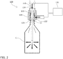
- a container-interior drying device 100 includes a gas ejector nozzle 110, a gas flow amplifying unit 120 that serves as a suction mechanism, and a gas supply unit 130 that supplies the gas ejector nozzle 110 and the gas flow amplifying unit 120 with gas, the gas ejector nozzle 110 being capable of being inserted into an interior of a container C through an opening C1 of the container C, the gas flow amplifying unit 120 being capable of facing a top of the opening C1 of the container C.
- the gas ejector nozzle 110 is configured to move upward and downward by a moving means (not shown) and to eject gas from its lower end tip.
- the gas flow amplifying unit 120 which includes a gas supply part 122 and a gas flow amplification path 121 that has a suction inlet 123 at the bottom and an ejection outlet 124 at the top, has the function of an amplifying mechanism as disclosed in Patent Literature 2, 3 or the like.
- the gas flow amplifying unit 120 ejects gas supplied to the gas supply part 122 at high speed toward the ejection outlet 124 along an inner periphery of the gas flow amplification path 121, and resultantly, sucks out gas from the suction inlet 123 to eject high-speed, high-pressure gas from the ejection outlet 124.
- the gas flow amplifying unit 120 is configured to move upward and downward by a moving means (not shown) independent of the means for moving the gas ejector nozzle 110.
- the gas flow amplifying unit 120 is positioned so as to allow the suction inlet 123 to face the top of the opening C1 of the container C and the gas ejector nozzle 110 to be disposed through the gas flow amplification path 121.
- gas flow amplifying unit 120 may be disposed in a fixed manner, so as not to move upward or downward.
- the gas supply unit 130 which supplies gas to the gas ejector nozzle 110 and the gas supply part 122 of the gas flow amplifying unit 120, may, for example, be composed of a gas flow path alone that is connected to a compressed gas supply source in a place where the container-interior drying device 100 according to the present embodiment is installed.
- the gas supply unit 130 may then include a regulating mechanism for attaining a pressure and flow rate appropriate to each of the gas ejector nozzle 110 and the gas supply part 122.
- any other-principle based suction mechanism that can suck out gas in the interior through the opening C1 of the container C can be used instead of the gas flow amplifying unit 120.
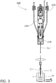
- Spraying a coating agent containing a high-volatile solvent, which is to be dried, on an inner wall surface of the container C is done by means of, for example, a coating device 200 as illustrated in Fig. 3 .
- the container C held by a container holding means H is moved to a position beneath a spray gun 210 and is stopped at the position. Then the spray gun 210 is moved down by a vertical drive mechanism 220 to insert a spray nozzle 211 into the interior of the container C.
- the spray gun 210 is rotated by a rotary drive mechanism 230. Concurrently, a coating agent L is ejected from an end tip of the spray nozzle 211. Then, while the spray gun 210 is moved up, the coating agent L is ejected from the end tip of the spray nozzle 211. This process allows the coating agent L to be sprayed uniformly on the inner wall surface of the container C.
- the container C that has undergone the application of the coating agent L is moved to a position beneath the gas flow amplifying unit 120 of the container-interior drying device 100 and is stopped at the position as illustrated in Fig. 1 .
- the gas flow amplifying unit 120 and the gas ejector nozzle 110 are moved down. As illustrated in Fig. 2 , the gas flow amplifying unit 120 is stopped at a position that allows the suction inlet 123 of the gas flow amplification path 121 to be spaced slightly from the opening C1 of the container C, whereas the gas ejector nozzle 110 is further moved down to enter the interior of the container C.
- dry air is ejected from the gas ejector nozzle 110 and the gas supply part 122 of the gas flow amplifying unit 120 is supplied with gas, causing dry air within the container C to be sucked.
- the space between the suction inlet 123 and the opening C1 of the container C is desirably as narrow as possible to the extent that eliminates deformation or adhesion to the suction inlet 123 of the container C per se due to negative pressure.
- the ejecting of dry air from the gas ejector nozzle 110 and the supply of gas to the gas supply part 122 of the gas flow amplifying unit 120 may be started concurrently with the starting of or after the completion of the moving down.
- dry air may be ejected from the gas ejector nozzle 110 while the gas ejector nozzle 110 is moved up and down or rotated.
- driving mechanisms similar to the vertical drive mechanism 220 and the rotary drive mechanism 230 in the above coating device 200 can be used.
- the gas ejector nozzle 110 and the gas flow amplifying unit 120 may be provided integrally with the spray nozzle 211 of the above coating device 200 to carry out the drying process by the gas ejector nozzle 110 and the gas flow amplifying unit 120, as part of the process of applying the coating agent L, after the coating process with the spray nozzle 211.
- feeding of the coating agent L to the spray gun 210 may be stopped to allow the spray nozzle 211, which would then eject dry air alone, to function as the gas ejector nozzle 110.
- the container-interior drying device 100 in the above embodiment is positioned so as to point the gas ejector nozzle 110 in the vertical direction
- the container-interior drying device 100 may be installed in any position, such as being positioned so as to point the gas ejector nozzle 110 in the horizontal direction.
- container-interior drying device and the container-interior drying method in the above embodiment are described as drying the coating agent applied on the container with dry air, the container-interior drying device and the container-interior drying method may be used to dry other liquids, such as rinse water remaining after a cleaning process.
- container-interior drying device and the container-interior drying method may be used for other applications, or to exert heating or cooling effect according to the gas used for the ejection or to exert other effects by blowing a special gas other than air.
Landscapes
- Engineering & Computer Science (AREA)
- Mechanical Engineering (AREA)
- General Engineering & Computer Science (AREA)
- Physics & Mathematics (AREA)
- Fluid Mechanics (AREA)
- Drying Of Solid Materials (AREA)
- Application Of Or Painting With Fluid Materials (AREA)
- Coating Apparatus (AREA)
- Nozzles (AREA)
Abstract
Description
- The present invention relates to a container-interior drying device and a container-interior drying method for drying an inner wall surface of a container.
- In general, plastic containers, which are formed easily and manufactured at lower costs, are widely used for various applications. However, putting viscous contents such as mayonnaise-like food within a plastic container causes the contents to easily stick on the inner wall surface of the container, resulting in a failure of using up the contents without leaving the contents within the container.
- In recent years, coating agents for improving the slipping down of contents have been developed. It is known that applying such a coating agent on the inner wall surface of the container improves the slip characteristic of the inner wall surface of the container, allowing contents within the container to be used up easily.
- In this regard, a possible approach to applying the coating agent uniformly on the inner wall surface of the container is to insert a nozzle as disclosed in Patent Literature 1 into the interior of the container and eject the coating agent while rotating the container.
-
- Patent Literature 1: Japanese Patent Application Publication No.
2005-118683 - Patent Literature 2: Japanese Patent Application Publication No.
H4-184000 - Patent Literature 3: Japanese Patent Application Publication No.
2006-291941 - In ejecting and applying a coating agent to the interior of the container, as mentioned above, a solution of the coating agent containing a high-volatile solvent is sprayed. To fully volatilize and dry the solvent and fix the coating agent on the inner wall surface of the container, applying high-temperature heat to the container with an oven is typically done.
- This method, however, requires a large scale oven to improve the efficiency in an entire filling line, and unfortunately, this requires large investment and large space for installing equipment.
- In addition, a container, such as a plastic container, composed of a resin having a low melting point can cause an undesired deformation of the container depending on temperatures of the oven, and then lowering the oven temperature can cause a prolongation of the drying time and thus a decrease in the efficiency of the entire filling line.
- Further, although another possible approach is to eject dry gas at the opening of the container toward the interior of the container to volatilize and dry the solvent, a container that needs applying a coating agent typically has a small opening, which does not allow for sufficient circulation of the gas, inevitably resulting in a prolongation of the drying time.
- The present invention solves the above problems, and the object thereof is to provide a container-interior drying device and a container-interior drying method capable of shortening the drying time and improving the efficiency in the entire filling line without causing container deformation, the device having a simple configuration and requiring little space for installation.
- A container-interior drying device according to the present invention is a device for drying an inner wall surface of a container and solves the above-mentioned problems by including a gas ejector nozzle capable of being inserted into an interior of the container through an opening of the container, a suction mechanism capable of facing the opening of the container, and a gas supply unit configured to supply the gas ejector nozzle with gas.
- In addition, a container-interior drying method according to the present invention is a method for drying an inner wall surface of a container and solves the above-mentioned problems by inserting a gas ejector nozzle into an interior of the container through an opening of the container, and ejecting gas from the gas ejector nozzle into the interior of the container and sucking out gas through the opening of the container by a suction mechanism positioned so as to face the opening of the container.
- A container-interior drying device according to claim 1 includes a gas ejector nozzle capable of being inserted into an interior of the container through an opening of the container, a suction mechanism capable of facing the opening of the container, and a gas supply unit configured to supply the gas ejector nozzle with gas. This facilitates blowing of dry air or the like into the interior of the container and enables suction of air within the container through the opening of the container by the suction mechanism, allowing gas within the container to be reliably sucked out through the opening of the container to allow gas within the container to fully circulate, even if a large amount of gas is ejected within the container.
- In consequence, the container-interior drying device, while having a simple configuration and requiring little space for installation, shortens drying time without causing container deformation, improving the efficiency in an entire filling line.
- Further, the container-interior drying device allows the gas ejector nozzle also to blow gas to the inner wall surface of the container, further facilitating the drying of the interior of the container.
- In the configuration according to claim 2, the suction mechanism is formed of a gas flow amplifying unit, the gas flow amplifying unit includes a gas supply part and a gas flow amplification path that has a suction inlet and an ejection outlet, and the suction inlet is positioned so as to face the opening of the container. This configuration enables suction of air within the container from the suction inlet using compressed gas, eliminating the need for equipment such as a vacuum apparatus, achieving a simpler configuration of the container-interior drying device and a smaller space for installing it.
- In the configuration according to claim 3, the gas supply unit is configured to supply the gas supply part of the gas flow amplifying unit with gas. This configuration eliminates the need for an independent driving source for sucking out air within the container, achieving a still smaller space for installing the container-interior drying device.
- In the configuration according to claim 4, the gas ejector nozzle is provided through the gas flow amplification path of the gas flow amplifying unit. This configuration positions the suction inlet of the gas flow amplifying unit so as to allow it to cover the entire opening of the container, enabling suction of a larger amount of gas.
- In the configuration according to claim 5, the container-interior drying device further includes means for moving the gas ejector nozzle. This configuration allows optional insertion and extraction of the gas ejector nozzle without moving the container, facilitating incorporation of the container-interior drying device into existing equipment including a container-conveyor line.
- Further, this configuration allows gas to be ejected from the gas ejector nozzle while the gas ejector nozzle is moved within the container, enabling a more reliable circulation of gas within the container.
- A container-interior drying method according to claim 6 includes inserting a gas ejector nozzle into an interior of the container through an opening of the container, and ejecting gas from the gas ejector nozzle into the interior of the container and sucking out gas through the opening of the container by a suction mechanism positioned so as to face the opening of the container. This configuration allows gas within the container to be reliably discharged to an exterior of the container to allow gas within the container to fully circulate, even if a large amount of gas is ejected within the container.
- In consequence, the container-interior drying method, while enabling equipment to have a simple configuration and further to require little space for installing the equipment, shortens a drying time without causing container deformation, improving the efficiency in an entire filling line.
- Further, the container-interior drying method allows blowing of gas to the inner wall surface of the container by the gas ejector nozzle, further facilitating the drying of the interior of the container.
- In the configuration according to claim 7, the suction mechanism is formed of a gas flow amplifying unit including a gas supply part and a gas flow amplification path that has a suction inlet and an ejection outlet, and the container-interior drying method includes supplying the gas ejector nozzle with gas to eject gas into the interior of the container and supplying the gas supply part of the gas flow amplifying unit with gas to suck out gas through the opening of the container. This configuration eliminates the need for equipment such as a vacuum apparatus, enabling equipment to have a simpler configuration and to require little space for installing the equipment.
-
- [
Fig. 1] Fig. 1 is a schematic illustration of a container-interior drying device according to an embodiment of the present invention. - [
Fig. 2] Fig. 2 is a schematic illustration of the container-interior drying device, in operation, according to the embodiment of the present invention. - [
Fig. 3] Fig. 3 is a reference illustration of a coating device. -
- 100
- Container-interior drying device
- 110
- Gas ejector nozzle
- 120
- Gas flow amplifying unit (suction mechanism)
- 121
- Gas flow amplification path
- 122
- Gas supply part
- 123
- Suction inlet
- 124
- Ejection outlet
- 130
- Gas supply unit
- 200
- Coating device
- 210
- Spray gun
- 211
- Spray nozzle
- 220
- Vertical drive mechanism
- 230
- Rotary drive mechanism
- C
- Container
- C1
- Opening
- L
- Coating agent
- H
- Container holding means
- As illustrated in
Figs. 1 and2 , a container-interior drying device 100 according to an embodiment of the present invention includes agas ejector nozzle 110, a gasflow amplifying unit 120 that serves as a suction mechanism, and agas supply unit 130 that supplies thegas ejector nozzle 110 and the gasflow amplifying unit 120 with gas, thegas ejector nozzle 110 being capable of being inserted into an interior of a container C through an opening C1 of the container C, the gasflow amplifying unit 120 being capable of facing a top of the opening C1 of the container C. - The
gas ejector nozzle 110 is configured to move upward and downward by a moving means (not shown) and to eject gas from its lower end tip. - The gas
flow amplifying unit 120, which includes agas supply part 122 and a gasflow amplification path 121 that has asuction inlet 123 at the bottom and anejection outlet 124 at the top, has the function of an amplifying mechanism as disclosed in Patent Literature 2, 3 or the like. The gasflow amplifying unit 120 ejects gas supplied to thegas supply part 122 at high speed toward theejection outlet 124 along an inner periphery of the gasflow amplification path 121, and resultantly, sucks out gas from thesuction inlet 123 to eject high-speed, high-pressure gas from theejection outlet 124. - Further, the gas
flow amplifying unit 120 is configured to move upward and downward by a moving means (not shown) independent of the means for moving thegas ejector nozzle 110. The gasflow amplifying unit 120 is positioned so as to allow thesuction inlet 123 to face the top of the opening C1 of the container C and thegas ejector nozzle 110 to be disposed through the gasflow amplification path 121. - It is noted that the gas
flow amplifying unit 120 may be disposed in a fixed manner, so as not to move upward or downward. - The
gas supply unit 130, which supplies gas to thegas ejector nozzle 110 and thegas supply part 122 of the gasflow amplifying unit 120, may, for example, be composed of a gas flow path alone that is connected to a compressed gas supply source in a place where the container-interior drying device 100 according to the present embodiment is installed. Alternatively, thegas supply unit 130 may then include a regulating mechanism for attaining a pressure and flow rate appropriate to each of thegas ejector nozzle 110 and thegas supply part 122. - Further, any other-principle based suction mechanism that can suck out gas in the interior through the opening C1 of the container C can be used instead of the gas
flow amplifying unit 120. - Now there will be described an embodiment of a container-interior drying method by means of the container-
interior drying device 100 as mentioned. - Spraying a coating agent containing a high-volatile solvent, which is to be dried, on an inner wall surface of the container C is done by means of, for example, a
coating device 200 as illustrated inFig. 3 . - The container C held by a container holding means H is moved to a position beneath a
spray gun 210 and is stopped at the position. Then thespray gun 210 is moved down by avertical drive mechanism 220 to insert aspray nozzle 211 into the interior of the container C. - At the timing when the
spray nozzle 211 has reached the lowest level, thespray gun 210 is rotated by arotary drive mechanism 230. Concurrently, a coating agent L is ejected from an end tip of thespray nozzle 211. Then, while thespray gun 210 is moved up, the coating agent L is ejected from the end tip of thespray nozzle 211. This process allows the coating agent L to be sprayed uniformly on the inner wall surface of the container C. - While having been held by the container holding means H, the container C that has undergone the application of the coating agent L is moved to a position beneath the gas
flow amplifying unit 120 of the container-interior drying device 100 and is stopped at the position as illustrated inFig. 1 . - Next, the gas
flow amplifying unit 120 and thegas ejector nozzle 110 are moved down. As illustrated inFig. 2 , the gasflow amplifying unit 120 is stopped at a position that allows thesuction inlet 123 of the gasflow amplification path 121 to be spaced slightly from the opening C1 of the container C, whereas thegas ejector nozzle 110 is further moved down to enter the interior of the container C. - Then, dry air is ejected from the
gas ejector nozzle 110 and thegas supply part 122 of the gasflow amplifying unit 120 is supplied with gas, causing dry air within the container C to be sucked. - In this regard, the space between the
suction inlet 123 and the opening C1 of the container C is desirably as narrow as possible to the extent that eliminates deformation or adhesion to thesuction inlet 123 of the container C per se due to negative pressure. - The ejecting of dry air from the
gas ejector nozzle 110 and the supply of gas to thegas supply part 122 of the gasflow amplifying unit 120 may be started concurrently with the starting of or after the completion of the moving down. - Alternatively, dry air may be ejected from the
gas ejector nozzle 110 while thegas ejector nozzle 110 is moved up and down or rotated. - For this operation, driving mechanisms similar to the
vertical drive mechanism 220 and therotary drive mechanism 230 in theabove coating device 200 can be used. - Alternatively, the
gas ejector nozzle 110 and the gasflow amplifying unit 120 may be provided integrally with thespray nozzle 211 of theabove coating device 200 to carry out the drying process by thegas ejector nozzle 110 and the gasflow amplifying unit 120, as part of the process of applying the coating agent L, after the coating process with thespray nozzle 211. - Further, after the coating process, feeding of the coating agent L to the
spray gun 210 may be stopped to allow thespray nozzle 211, which would then eject dry air alone, to function as thegas ejector nozzle 110. - Although, the container-
interior drying device 100 in the above embodiment is positioned so as to point thegas ejector nozzle 110 in the vertical direction, the container-interior drying device 100 may be installed in any position, such as being positioned so as to point thegas ejector nozzle 110 in the horizontal direction. - Further, although the container-interior drying device and the container-interior drying method in the above embodiment are described as drying the coating agent applied on the container with dry air, the container-interior drying device and the container-interior drying method may be used to dry other liquids, such as rinse water remaining after a cleaning process.
- Further, the container-interior drying device and the container-interior drying method may be used for other applications, or to exert heating or cooling effect according to the gas used for the ejection or to exert other effects by blowing a special gas other than air.
Claims (7)
- A container-interior drying device for drying an inner wall surface of a container, the device comprising:a gas ejector nozzle capable of being inserted into an interior of the container through an opening of the container;a suction mechanism capable of facing the opening of the container; anda gas supply unit configured to supply the gas ejector nozzle with gas.
- The container-interior drying device according to claim 1, wherein
the suction mechanism is formed of a gas flow amplifying unit,
the gas flow amplifying unit includes a gas supply part and a gas flow amplification path that has a suction inlet and an ejection outlet, and
the suction inlet is positioned so as to face the opening of the container. - The container-interior drying device according to claim 2, wherein the gas supply unit is configured to supply the gas supply part of the gas flow amplifying unit with gas.
- The container-interior drying device according to claim 2 or claim 3, wherein the gas ejector nozzle is provided through the gas flow amplification path of the gas flow amplifying unit.
- The container-interior drying device according to any one of claims 1 to 4, further comprising means for moving the gas ejector nozzle.
- A container-interior drying method for drying an inner wall surface of a container, the method comprising:inserting a gas ejector nozzle into an interior of the container through an opening of the container; andejecting gas from the gas ejector nozzle into the interior of the container and sucking out gas through the opening of the container by a suction mechanism positioned so as to face the opening of the container.
- The container-interior drying method according to claim 6, wherein
the suction mechanism is formed of a gas flow amplifying unit including a gas supply part and a gas flow amplification path that has a suction inlet and an ejection outlet, and
the method comprises supplying the gas ejector nozzle with gas to eject gas into the interior of the container and supplying the gas supply part of the gas flow amplifying unit with gas to suck out gas through the opening of the container.
Applications Claiming Priority (2)
| Application Number | Priority Date | Filing Date | Title |
|---|---|---|---|
| JP2014247881A JP6520088B2 (en) | 2014-12-08 | 2014-12-08 | Container internal drying apparatus and container internal drying method |
| PCT/JP2015/080364 WO2016092963A1 (en) | 2014-12-08 | 2015-10-28 | Container-interior drying device and container-interior drying method |
Publications (3)
| Publication Number | Publication Date |
|---|---|
| EP3232147A1 true EP3232147A1 (en) | 2017-10-18 |
| EP3232147A4 EP3232147A4 (en) | 2018-08-08 |
| EP3232147B1 EP3232147B1 (en) | 2021-12-08 |
Family
ID=56107158
Family Applications (1)
| Application Number | Title | Priority Date | Filing Date |
|---|---|---|---|
| EP15866752.7A Active EP3232147B1 (en) | 2014-12-08 | 2015-10-28 | Container-interior drying method |
Country Status (6)
| Country | Link |
|---|---|
| US (1) | US10352333B2 (en) |
| EP (1) | EP3232147B1 (en) |
| JP (1) | JP6520088B2 (en) |
| KR (1) | KR20170091129A (en) |
| CN (1) | CN107003068B (en) |
| WO (1) | WO2016092963A1 (en) |
Families Citing this family (2)
| Publication number | Priority date | Publication date | Assignee | Title |
|---|---|---|---|---|
| US10914521B2 (en) * | 2019-01-24 | 2021-02-09 | Versum Materials Us, Llc | System and method for drying and analytical testing of containers |
| CN114014246B (en) * | 2021-11-09 | 2023-04-07 | 扬州市天诗美景日化有限公司 | Drying and sterilizing equipment for shampoo bottle |
Family Cites Families (28)
| Publication number | Priority date | Publication date | Assignee | Title |
|---|---|---|---|---|
| GB123769A (en) * | 1916-09-04 | 1919-10-02 | Emile Louis Alfred Savy | Improvements in Drying Apparatus for Bottles, Jars, Cans or the like Receptacles. |
| US2240364A (en) * | 1939-01-20 | 1941-04-29 | Portland Company | Method of treating the interiors of containers |
| US2509396A (en) * | 1945-03-26 | 1950-05-30 | Carl F Mayer | Drying apparatus for molds |
| US2845934A (en) * | 1953-04-29 | 1958-08-05 | Portland Company | Apparatus for use in cleaning the interiors of barrels |
| JPS584582B2 (en) * | 1978-03-03 | 1983-01-27 | 株式会社大谷電機製作所 | Internal coating equipment |
| JPS5851961A (en) * | 1981-09-21 | 1983-03-26 | Kinzo Fujii | Finishing of paint film on inside wall of pipe and container |
| JPS59212677A (en) * | 1983-05-18 | 1984-12-01 | 大日本印刷株式会社 | Drier for inside of vessel |
| JPH02153846A (en) * | 1988-12-07 | 1990-06-13 | Murase Glass Kk | Production of low-alkali glass container |
| US4987001A (en) | 1989-02-09 | 1991-01-22 | Nordson Corporation | Method and apparatus for coating the interior surface of hollow, tubular articles |
| FR2645951A1 (en) * | 1989-04-14 | 1990-10-19 | Cgc Entr | Method for drying containers and installation for drying such containers |
| JP2713814B2 (en) * | 1990-11-15 | 1998-02-16 | 三井造船株式会社 | Ejector for compressible fluid |
| GB2272273A (en) * | 1992-11-10 | 1994-05-11 | Agma Plc | Apparatus for washing and drying containers |
| JPH0752555Y2 (en) * | 1993-08-23 | 1995-11-29 | ロザイ工業株式会社 | Can dryer oven |
| CN2200168Y (en) * | 1994-05-19 | 1995-06-07 | 陈启松 | Drying machine |
| JP3195209B2 (en) * | 1995-10-13 | 2001-08-06 | 象印マホービン株式会社 | Container inner surface coating method |
| FR2775064B1 (en) * | 1998-02-16 | 2000-05-05 | Sidel Sa | METHOD FOR DRYING HOLLOW BODIES AND DEVICE FOR CARRYING OUT SAID |
| JP2000018822A (en) * | 1998-07-03 | 2000-01-18 | Ishikawajima Harima Heavy Ind Co Ltd | Method and device for drying goods |
| JP3389111B2 (en) * | 1998-08-10 | 2003-03-24 | コスモス産業株式会社 | Flexible container bag cleaning device |
| JP2002308231A (en) * | 2001-04-19 | 2002-10-23 | Hokkai Can Co Ltd | Cleaning apparatus for plastic bottle |
| JP2005118683A (en) | 2003-10-17 | 2005-05-12 | Mitsubishi Electric Corp | Coating device and coating method |
| JP2006291941A (en) * | 2005-04-05 | 2006-10-26 | Fukuhara Co Ltd | Method and device for amplifying compressed air quantity |
| CN2864182Y (en) * | 2005-12-08 | 2007-01-31 | 贾树峰 | Jet draught fan |
| KR101102440B1 (en) * | 2008-07-31 | 2012-01-05 | 이익재 | Different thing removal device |
| CN101592169B (en) * | 2009-05-22 | 2012-10-17 | 汪京涛 | Pneumatic suction fan |
| DE102010002633A1 (en) * | 2010-03-05 | 2011-09-08 | Dürr Ecoclean GmbH | Tool for cleaning and / or drying a cavity |
| CN201771874U (en) * | 2010-08-05 | 2011-03-23 | 无锡英威华耀科技有限公司 | Air jetting amplifier |
| CN101968299B (en) * | 2010-10-29 | 2012-05-09 | 武善东 | Method for drying materials by utilizing superheated steam |
| CN203685712U (en) * | 2014-01-03 | 2014-07-02 | 谭文玉 | Air amplifier |
-
2014
- 2014-12-08 JP JP2014247881A patent/JP6520088B2/en active Active
-
2015
- 2015-10-28 EP EP15866752.7A patent/EP3232147B1/en active Active
- 2015-10-28 WO PCT/JP2015/080364 patent/WO2016092963A1/en active Application Filing
- 2015-10-28 KR KR1020177017923A patent/KR20170091129A/en not_active Application Discontinuation
- 2015-10-28 CN CN201580064400.1A patent/CN107003068B/en active Active
-
2017
- 2017-06-05 US US15/613,524 patent/US10352333B2/en active Active
Also Published As
| Publication number | Publication date |
|---|---|
| US10352333B2 (en) | 2019-07-16 |
| CN107003068A (en) | 2017-08-01 |
| JP6520088B2 (en) | 2019-05-29 |
| EP3232147B1 (en) | 2021-12-08 |
| EP3232147A4 (en) | 2018-08-08 |
| CN107003068B (en) | 2019-06-21 |
| US20170268538A1 (en) | 2017-09-21 |
| KR20170091129A (en) | 2017-08-08 |
| JP2016109364A (en) | 2016-06-20 |
| WO2016092963A1 (en) | 2016-06-16 |
Similar Documents
| Publication | Publication Date | Title |
|---|---|---|
| US10569289B2 (en) | Application apparatus | |
| US10352333B2 (en) | Container-interior drying device and container-interior drying method | |
| JP2002308231A (en) | Cleaning apparatus for plastic bottle | |
| EP3101430B1 (en) | Automatic analysis device | |
| JP2008174246A (en) | Waterdrop removing apparatus for container, and ring-shaped air nozzle for waterdrop removing apparatus | |
| US20210086216A1 (en) | Container processing system | |
| JP2008285301A (en) | Article conveying method and article conveying device | |
| CN105478298A (en) | Vacuum paint dipping dryer | |
| US20210086217A1 (en) | Container processing system | |
| WO2015170198A1 (en) | A method for coating an inner wall of a container | |
| WO2016013424A1 (en) | Cooling device and multi-chamber heat treatment device | |
| JP2009255079A (en) | Injection amount control method for coating apparatus and apparatus | |
| CN206485048U (en) | The automatic very fast cleaning device of automatic viscosity controller | |
| JP5954114B2 (en) | Sampling device | |
| JP6418830B2 (en) | Cooling device and multi-chamber heat treatment device | |
| JP2013188453A5 (en) | ||
| KR101666150B1 (en) | Cleaning apparatus of ampoule cap for injection | |
| JP2016109364A5 (en) | ||
| KR101591242B1 (en) | Work discharge device | |
| JP6490560B2 (en) | Nozzle cleaning device | |
| TW201603903A (en) | Method for producing and method for cleaning beverage vessel, and cleaning device | |
| CN218993929U (en) | Experimental vacuum pulse dryer | |
| JP2009006241A (en) | Cleaning apparatus | |
| JP6333083B2 (en) | Film forming apparatus and film forming method | |
| CN112706526A (en) | Method and system for reducing solvent consumption of printer |
Legal Events
| Date | Code | Title | Description |
|---|---|---|---|
| STAA | Information on the status of an ep patent application or granted ep patent |
Free format text: STATUS: THE INTERNATIONAL PUBLICATION HAS BEEN MADE |
|
| PUAI | Public reference made under article 153(3) epc to a published international application that has entered the european phase |
Free format text: ORIGINAL CODE: 0009012 |
|
| STAA | Information on the status of an ep patent application or granted ep patent |
Free format text: STATUS: REQUEST FOR EXAMINATION WAS MADE |
|
| 17P | Request for examination filed |
Effective date: 20170628 |
|
| AK | Designated contracting states |
Kind code of ref document: A1 Designated state(s): AL AT BE BG CH CY CZ DE DK EE ES FI FR GB GR HR HU IE IS IT LI LT LU LV MC MK MT NL NO PL PT RO RS SE SI SK SM TR |
|
| AX | Request for extension of the european patent |
Extension state: BA ME |
|
| DAV | Request for validation of the european patent (deleted) | ||
| DAX | Request for extension of the european patent (deleted) | ||
| REG | Reference to a national code |
Ref country code: DE Ref legal event code: R079 Ref document number: 602015075695 Country of ref document: DE Free format text: PREVIOUS MAIN CLASS: F26B0009000000 Ipc: F26B0021000000 |
|
| A4 | Supplementary search report drawn up and despatched |
Effective date: 20180709 |
|
| RIC1 | Information provided on ipc code assigned before grant |
Ipc: B05C 9/12 20060101ALI20180703BHEP Ipc: F26B 21/00 20060101AFI20180703BHEP Ipc: B05D 3/04 20060101ALI20180703BHEP Ipc: F26B 9/00 20060101ALI20180703BHEP |
|
| STAA | Information on the status of an ep patent application or granted ep patent |
Free format text: STATUS: EXAMINATION IS IN PROGRESS |
|
| 17Q | First examination report despatched |
Effective date: 20200313 |
|
| STAA | Information on the status of an ep patent application or granted ep patent |
Free format text: STATUS: EXAMINATION IS IN PROGRESS |
|
| GRAP | Despatch of communication of intention to grant a patent |
Free format text: ORIGINAL CODE: EPIDOSNIGR1 |
|
| STAA | Information on the status of an ep patent application or granted ep patent |
Free format text: STATUS: GRANT OF PATENT IS INTENDED |
|
| INTG | Intention to grant announced |
Effective date: 20210629 |
|
| GRAS | Grant fee paid |
Free format text: ORIGINAL CODE: EPIDOSNIGR3 |
|
| GRAA | (expected) grant |
Free format text: ORIGINAL CODE: 0009210 |
|
| STAA | Information on the status of an ep patent application or granted ep patent |
Free format text: STATUS: THE PATENT HAS BEEN GRANTED |
|
| AK | Designated contracting states |
Kind code of ref document: B1 Designated state(s): AL AT BE BG CH CY CZ DE DK EE ES FI FR GB GR HR HU IE IS IT LI LT LU LV MC MK MT NL NO PL PT RO RS SE SI SK SM TR |
|
| REG | Reference to a national code |
Ref country code: GB Ref legal event code: FG4D |
|
| REG | Reference to a national code |
Ref country code: AT Ref legal event code: REF Ref document number: 1454082 Country of ref document: AT Kind code of ref document: T Effective date: 20211215 Ref country code: CH Ref legal event code: EP |
|
| REG | Reference to a national code |
Ref country code: DE Ref legal event code: R096 Ref document number: 602015075695 Country of ref document: DE |
|
| REG | Reference to a national code |
Ref country code: IE Ref legal event code: FG4D |
|
| REG | Reference to a national code |
Ref country code: LT Ref legal event code: MG9D |
|
| REG | Reference to a national code |
Ref country code: NL Ref legal event code: MP Effective date: 20211208 |
|
| PG25 | Lapsed in a contracting state [announced via postgrant information from national office to epo] |
Ref country code: RS Free format text: LAPSE BECAUSE OF FAILURE TO SUBMIT A TRANSLATION OF THE DESCRIPTION OR TO PAY THE FEE WITHIN THE PRESCRIBED TIME-LIMIT Effective date: 20211208 Ref country code: LT Free format text: LAPSE BECAUSE OF FAILURE TO SUBMIT A TRANSLATION OF THE DESCRIPTION OR TO PAY THE FEE WITHIN THE PRESCRIBED TIME-LIMIT Effective date: 20211208 Ref country code: FI Free format text: LAPSE BECAUSE OF FAILURE TO SUBMIT A TRANSLATION OF THE DESCRIPTION OR TO PAY THE FEE WITHIN THE PRESCRIBED TIME-LIMIT Effective date: 20211208 Ref country code: BG Free format text: LAPSE BECAUSE OF FAILURE TO SUBMIT A TRANSLATION OF THE DESCRIPTION OR TO PAY THE FEE WITHIN THE PRESCRIBED TIME-LIMIT Effective date: 20220308 |
|
| REG | Reference to a national code |
Ref country code: AT Ref legal event code: MK05 Ref document number: 1454082 Country of ref document: AT Kind code of ref document: T Effective date: 20211208 |
|
| PG25 | Lapsed in a contracting state [announced via postgrant information from national office to epo] |
Ref country code: SE Free format text: LAPSE BECAUSE OF FAILURE TO SUBMIT A TRANSLATION OF THE DESCRIPTION OR TO PAY THE FEE WITHIN THE PRESCRIBED TIME-LIMIT Effective date: 20211208 Ref country code: NO Free format text: LAPSE BECAUSE OF FAILURE TO SUBMIT A TRANSLATION OF THE DESCRIPTION OR TO PAY THE FEE WITHIN THE PRESCRIBED TIME-LIMIT Effective date: 20220308 Ref country code: LV Free format text: LAPSE BECAUSE OF FAILURE TO SUBMIT A TRANSLATION OF THE DESCRIPTION OR TO PAY THE FEE WITHIN THE PRESCRIBED TIME-LIMIT Effective date: 20211208 Ref country code: HR Free format text: LAPSE BECAUSE OF FAILURE TO SUBMIT A TRANSLATION OF THE DESCRIPTION OR TO PAY THE FEE WITHIN THE PRESCRIBED TIME-LIMIT Effective date: 20211208 Ref country code: GR Free format text: LAPSE BECAUSE OF FAILURE TO SUBMIT A TRANSLATION OF THE DESCRIPTION OR TO PAY THE FEE WITHIN THE PRESCRIBED TIME-LIMIT Effective date: 20220309 Ref country code: ES Free format text: LAPSE BECAUSE OF FAILURE TO SUBMIT A TRANSLATION OF THE DESCRIPTION OR TO PAY THE FEE WITHIN THE PRESCRIBED TIME-LIMIT Effective date: 20211208 |
|
| PG25 | Lapsed in a contracting state [announced via postgrant information from national office to epo] |
Ref country code: NL Free format text: LAPSE BECAUSE OF FAILURE TO SUBMIT A TRANSLATION OF THE DESCRIPTION OR TO PAY THE FEE WITHIN THE PRESCRIBED TIME-LIMIT Effective date: 20211208 |
|
| PG25 | Lapsed in a contracting state [announced via postgrant information from national office to epo] |
Ref country code: SM Free format text: LAPSE BECAUSE OF FAILURE TO SUBMIT A TRANSLATION OF THE DESCRIPTION OR TO PAY THE FEE WITHIN THE PRESCRIBED TIME-LIMIT Effective date: 20211208 Ref country code: SK Free format text: LAPSE BECAUSE OF FAILURE TO SUBMIT A TRANSLATION OF THE DESCRIPTION OR TO PAY THE FEE WITHIN THE PRESCRIBED TIME-LIMIT Effective date: 20211208 Ref country code: RO Free format text: LAPSE BECAUSE OF FAILURE TO SUBMIT A TRANSLATION OF THE DESCRIPTION OR TO PAY THE FEE WITHIN THE PRESCRIBED TIME-LIMIT Effective date: 20211208 Ref country code: PT Free format text: LAPSE BECAUSE OF FAILURE TO SUBMIT A TRANSLATION OF THE DESCRIPTION OR TO PAY THE FEE WITHIN THE PRESCRIBED TIME-LIMIT Effective date: 20220408 Ref country code: EE Free format text: LAPSE BECAUSE OF FAILURE TO SUBMIT A TRANSLATION OF THE DESCRIPTION OR TO PAY THE FEE WITHIN THE PRESCRIBED TIME-LIMIT Effective date: 20211208 Ref country code: CZ Free format text: LAPSE BECAUSE OF FAILURE TO SUBMIT A TRANSLATION OF THE DESCRIPTION OR TO PAY THE FEE WITHIN THE PRESCRIBED TIME-LIMIT Effective date: 20211208 |
|
| PG25 | Lapsed in a contracting state [announced via postgrant information from national office to epo] |
Ref country code: PL Free format text: LAPSE BECAUSE OF FAILURE TO SUBMIT A TRANSLATION OF THE DESCRIPTION OR TO PAY THE FEE WITHIN THE PRESCRIBED TIME-LIMIT Effective date: 20211208 Ref country code: AT Free format text: LAPSE BECAUSE OF FAILURE TO SUBMIT A TRANSLATION OF THE DESCRIPTION OR TO PAY THE FEE WITHIN THE PRESCRIBED TIME-LIMIT Effective date: 20211208 |
|
| REG | Reference to a national code |
Ref country code: DE Ref legal event code: R097 Ref document number: 602015075695 Country of ref document: DE |
|
| PG25 | Lapsed in a contracting state [announced via postgrant information from national office to epo] |
Ref country code: IS Free format text: LAPSE BECAUSE OF FAILURE TO SUBMIT A TRANSLATION OF THE DESCRIPTION OR TO PAY THE FEE WITHIN THE PRESCRIBED TIME-LIMIT Effective date: 20220408 |
|
| PLBE | No opposition filed within time limit |
Free format text: ORIGINAL CODE: 0009261 |
|
| STAA | Information on the status of an ep patent application or granted ep patent |
Free format text: STATUS: NO OPPOSITION FILED WITHIN TIME LIMIT |
|
| PG25 | Lapsed in a contracting state [announced via postgrant information from national office to epo] |
Ref country code: DK Free format text: LAPSE BECAUSE OF FAILURE TO SUBMIT A TRANSLATION OF THE DESCRIPTION OR TO PAY THE FEE WITHIN THE PRESCRIBED TIME-LIMIT Effective date: 20211208 Ref country code: AL Free format text: LAPSE BECAUSE OF FAILURE TO SUBMIT A TRANSLATION OF THE DESCRIPTION OR TO PAY THE FEE WITHIN THE PRESCRIBED TIME-LIMIT Effective date: 20211208 |
|
| 26N | No opposition filed |
Effective date: 20220909 |
|
| PG25 | Lapsed in a contracting state [announced via postgrant information from national office to epo] |
Ref country code: SI Free format text: LAPSE BECAUSE OF FAILURE TO SUBMIT A TRANSLATION OF THE DESCRIPTION OR TO PAY THE FEE WITHIN THE PRESCRIBED TIME-LIMIT Effective date: 20211208 |
|
| PG25 | Lapsed in a contracting state [announced via postgrant information from national office to epo] |
Ref country code: MC Free format text: LAPSE BECAUSE OF FAILURE TO SUBMIT A TRANSLATION OF THE DESCRIPTION OR TO PAY THE FEE WITHIN THE PRESCRIBED TIME-LIMIT Effective date: 20211208 |
|
| REG | Reference to a national code |
Ref country code: CH Ref legal event code: PL |
|
| REG | Reference to a national code |
Ref country code: BE Ref legal event code: MM Effective date: 20221031 |
|
| PG25 | Lapsed in a contracting state [announced via postgrant information from national office to epo] |
Ref country code: LU Free format text: LAPSE BECAUSE OF NON-PAYMENT OF DUE FEES Effective date: 20221028 |
|
| PG25 | Lapsed in a contracting state [announced via postgrant information from national office to epo] |
Ref country code: LI Free format text: LAPSE BECAUSE OF NON-PAYMENT OF DUE FEES Effective date: 20221031 Ref country code: CH Free format text: LAPSE BECAUSE OF NON-PAYMENT OF DUE FEES Effective date: 20221031 |
|
| PG25 | Lapsed in a contracting state [announced via postgrant information from national office to epo] |
Ref country code: BE Free format text: LAPSE BECAUSE OF NON-PAYMENT OF DUE FEES Effective date: 20221031 |
|
| PG25 | Lapsed in a contracting state [announced via postgrant information from national office to epo] |
Ref country code: IE Free format text: LAPSE BECAUSE OF NON-PAYMENT OF DUE FEES Effective date: 20221028 |
|
| PGFP | Annual fee paid to national office [announced via postgrant information from national office to epo] |
Ref country code: GB Payment date: 20231020 Year of fee payment: 9 |
|
| PGFP | Annual fee paid to national office [announced via postgrant information from national office to epo] |
Ref country code: IT Payment date: 20231026 Year of fee payment: 9 Ref country code: FR Payment date: 20231026 Year of fee payment: 9 Ref country code: DE Payment date: 20231020 Year of fee payment: 9 |
|
| PG25 | Lapsed in a contracting state [announced via postgrant information from national office to epo] |
Ref country code: HU Free format text: LAPSE BECAUSE OF FAILURE TO SUBMIT A TRANSLATION OF THE DESCRIPTION OR TO PAY THE FEE WITHIN THE PRESCRIBED TIME-LIMIT; INVALID AB INITIO Effective date: 20151028 |