WO2016092963A1 - Container-interior drying device and container-interior drying method - Google Patents
Container-interior drying device and container-interior drying method Download PDFInfo
- Publication number
- WO2016092963A1 WO2016092963A1 PCT/JP2015/080364 JP2015080364W WO2016092963A1 WO 2016092963 A1 WO2016092963 A1 WO 2016092963A1 JP 2015080364 W JP2015080364 W JP 2015080364W WO 2016092963 A1 WO2016092963 A1 WO 2016092963A1
- Authority
- WO
- WIPO (PCT)
- Prior art keywords
- container
- gas
- ejection nozzle
- mouth
- drying device
- Prior art date
Links
Images

Classifications
-
- F—MECHANICAL ENGINEERING; LIGHTING; HEATING; WEAPONS; BLASTING
- F04—POSITIVE - DISPLACEMENT MACHINES FOR LIQUIDS; PUMPS FOR LIQUIDS OR ELASTIC FLUIDS
- F04F—PUMPING OF FLUID BY DIRECT CONTACT OF ANOTHER FLUID OR BY USING INERTIA OF FLUID TO BE PUMPED; SIPHONS
- F04F5/00—Jet pumps, i.e. devices in which flow is induced by pressure drop caused by velocity of another fluid flow
- F04F5/14—Jet pumps, i.e. devices in which flow is induced by pressure drop caused by velocity of another fluid flow the inducing fluid being elastic fluid
- F04F5/24—Jet pumps, i.e. devices in which flow is induced by pressure drop caused by velocity of another fluid flow the inducing fluid being elastic fluid displacing liquids, e.g. containing solids, or liquids and elastic fluids
-
- F—MECHANICAL ENGINEERING; LIGHTING; HEATING; WEAPONS; BLASTING
- F26—DRYING
- F26B—DRYING SOLID MATERIALS OR OBJECTS BY REMOVING LIQUID THEREFROM
- F26B9/00—Machines or apparatus for drying solid materials or objects at rest or with only local agitation; Domestic airing cupboards
-
- B—PERFORMING OPERATIONS; TRANSPORTING
- B05—SPRAYING OR ATOMISING IN GENERAL; APPLYING FLUENT MATERIALS TO SURFACES, IN GENERAL
- B05B—SPRAYING APPARATUS; ATOMISING APPARATUS; NOZZLES
- B05B7/00—Spraying apparatus for discharge of liquids or other fluent materials from two or more sources, e.g. of liquid and air, of powder and gas
- B05B7/02—Spray pistols; Apparatus for discharge
- B05B7/08—Spray pistols; Apparatus for discharge with separate outlet orifices, e.g. to form parallel jets, i.e. the axis of the jets being parallel, to form intersecting jets, i.e. the axis of the jets converging but not necessarily intersecting at a point
- B05B7/0807—Spray pistols; Apparatus for discharge with separate outlet orifices, e.g. to form parallel jets, i.e. the axis of the jets being parallel, to form intersecting jets, i.e. the axis of the jets converging but not necessarily intersecting at a point to form intersecting jets
- B05B7/0815—Spray pistols; Apparatus for discharge with separate outlet orifices, e.g. to form parallel jets, i.e. the axis of the jets being parallel, to form intersecting jets, i.e. the axis of the jets converging but not necessarily intersecting at a point to form intersecting jets with at least one gas jet intersecting a jet constituted by a liquid or a mixture containing a liquid for controlling the shape of the latter
- B05B7/0823—Spray pistols; Apparatus for discharge with separate outlet orifices, e.g. to form parallel jets, i.e. the axis of the jets being parallel, to form intersecting jets, i.e. the axis of the jets converging but not necessarily intersecting at a point to form intersecting jets with at least one gas jet intersecting a jet constituted by a liquid or a mixture containing a liquid for controlling the shape of the latter comprising a rotatable spray pattern adjusting plate controlling the flow rate of the spray shaping gas jets
-
- B—PERFORMING OPERATIONS; TRANSPORTING
- B05—SPRAYING OR ATOMISING IN GENERAL; APPLYING FLUENT MATERIALS TO SURFACES, IN GENERAL
- B05D—PROCESSES FOR APPLYING FLUENT MATERIALS TO SURFACES, IN GENERAL
- B05D3/00—Pretreatment of surfaces to which liquids or other fluent materials are to be applied; After-treatment of applied coatings, e.g. intermediate treating of an applied coating preparatory to subsequent applications of liquids or other fluent materials
- B05D3/04—Pretreatment of surfaces to which liquids or other fluent materials are to be applied; After-treatment of applied coatings, e.g. intermediate treating of an applied coating preparatory to subsequent applications of liquids or other fluent materials by exposure to gases
-
- B—PERFORMING OPERATIONS; TRANSPORTING
- B08—CLEANING
- B08B—CLEANING IN GENERAL; PREVENTION OF FOULING IN GENERAL
- B08B9/00—Cleaning hollow articles by methods or apparatus specially adapted thereto
- B08B9/08—Cleaning containers, e.g. tanks
- B08B9/0804—Cleaning containers having tubular shape, e.g. casks, barrels, drums
- B08B9/0813—Cleaning containers having tubular shape, e.g. casks, barrels, drums by the force of jets or sprays
-
- F—MECHANICAL ENGINEERING; LIGHTING; HEATING; WEAPONS; BLASTING
- F26—DRYING
- F26B—DRYING SOLID MATERIALS OR OBJECTS BY REMOVING LIQUID THEREFROM
- F26B21/00—Arrangements or duct systems, e.g. in combination with pallet boxes, for supplying and controlling air or gases for drying solid materials or objects
- F26B21/006—Arrangements or duct systems, e.g. in combination with pallet boxes, for supplying and controlling air or gases for drying solid materials or objects the gas supply or exhaust being effected through hollow spaces or cores in the materials or objects, e.g. tubes, pipes, bottles
-
- B—PERFORMING OPERATIONS; TRANSPORTING
- B05—SPRAYING OR ATOMISING IN GENERAL; APPLYING FLUENT MATERIALS TO SURFACES, IN GENERAL
- B05C—APPARATUS FOR APPLYING FLUENT MATERIALS TO SURFACES, IN GENERAL
- B05C9/00—Apparatus or plant for applying liquid or other fluent material to surfaces by means not covered by any preceding group, or in which the means of applying the liquid or other fluent material is not important
- B05C9/08—Apparatus or plant for applying liquid or other fluent material to surfaces by means not covered by any preceding group, or in which the means of applying the liquid or other fluent material is not important for applying liquid or other fluent material and performing an auxiliary operation
- B05C9/12—Apparatus or plant for applying liquid or other fluent material to surfaces by means not covered by any preceding group, or in which the means of applying the liquid or other fluent material is not important for applying liquid or other fluent material and performing an auxiliary operation the auxiliary operation being performed after the application
Definitions
- the present invention relates to a container internal drying device and a container internal drying method for drying a container inner wall surface.
- plastic containers are widely used for various applications because they are easy to mold and can be manufactured at low cost.
- viscous contents such as mayonnaise-like foods are injected, the contents adhere to the inner wall of the container. Since it was easy, there was a problem that it was difficult to use up without leaving the contents in the container.
- coating agents that improve the slidability of contents has progressed. When such coating agents are applied to the inner wall surface of a container, the slidability of the inner wall surface of the container is improved and the contents in the container can be easily It is known that it can be used up quickly. Therefore, as a measure for uniformly applying the coating agent to the inner wall surface of the container, it is conceivable to insert a nozzle as shown in Patent Document 1 into the container and rotate the container to eject the coating agent.
- the present invention solves the above-described problems, has a simple configuration, requires a small installation space, can shorten the drying time, and improves the efficiency of the entire filling line without causing container deformation. It is an object of the present invention to provide a container internal drying device and a container internal drying method.
- a container internal drying device is a container internal drying device for drying an inner wall surface of a container, a gas ejection nozzle that can be inserted into the container from the container mouth, a suction mechanism that can face the container mouth, By providing a gas supply unit that supplies gas to the gas ejection nozzle, the problem is solved.
- the container internal drying method according to the present invention is a container internal drying method for drying the inner wall surface of a container, wherein a gas ejection nozzle is inserted into the container from the container mouth, and gas is introduced into the container from the gas ejection nozzle.
- the above-described problem is solved by ejecting gas and sucking gas from the container mouth by a suction mechanism disposed opposite to the container mouth.
- the gas ejection nozzle that can be inserted into the container from the container mouth, the suction mechanism that can face the container mouth, and the gas supply that supplies the gas to the gas ejection nozzle
- the suction mechanism that can face the container mouth
- the gas supply that supplies the gas to the gas ejection nozzle
- the suction mechanism includes the airflow amplification unit
- the airflow amplification unit includes the gas supply unit, the airflow amplification channel unit including the suction port and the jet port, and the suction port.
- the gas supply unit supplies the gas to the gas supply unit of the airflow amplification unit, so that an independent drive source for sucking the gas in the container is not required, and further installed. Space can be reduced.
- the gas ejection nozzle is provided so as to penetrate through the airflow amplification flow path portion of the airflow amplification unit, so that the suction port of the airflow amplification unit is the entire container mouth portion. It is possible to arrange so as to cover the gas, and a large amount of gas can be sucked.
- the existing container transport line Etc. can be easily incorporated into the above. Further, since the gas can be ejected while moving in the container, the gas can be circulated more sufficiently in the container.
- the gas ejection nozzle is inserted into the container from the container mouth, and the gas is ejected from the gas ejection nozzle into the container, and is disposed opposite to the container mouth.
- the suction mechanism includes an airflow amplification unit including a gas supply unit and an airflow amplification channel unit having an inlet and an outlet, and gas is supplied to the gas ejection nozzle.
- Supplying and ejecting gas inside the container, and supplying gas to the gas supply part of the airflow amplification unit and sucking the gas from the container mouth part eliminates the need for equipment such as a vacuum device, and makes it simpler The installation space can be reduced.
- SYMBOLS 100 Container inside drying apparatus 110 ... Gas ejection nozzle 120 ... Air flow amplification unit (suction mechanism) 121 ... Airflow amplification flow path part 122 ... Gas supply part 123 ... Suction port 124 ... Spout port 130 ... Gas supply unit 200 ... Application device 210 ... Spray gun 211 ... ⁇ Spray nozzle 220 ... Vertical drive mechanism 230 ... Rotation drive mechanism C ... Container C1 ... Mouth part L ... Coating agent H ... Container holding means
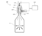
- a container internal drying apparatus 100 includes a gas ejection nozzle 110 that can be inserted into a container C from a mouth C1 of the container C, and a mouth of the container C.
- An airflow amplification unit 120 that is a suction mechanism that can be opposed to the upper side of the part C1, and a gas supply unit 130 that supplies gas to the gas ejection nozzle 110 and the airflow amplification unit 120 are provided.
- the gas ejection nozzle 110 is configured to be movable in the vertical direction by a moving means (not shown), and is configured to eject gas from its lower end.
- the airflow amplifying unit 120 includes a gas supply unit 122 and an airflow amplifying channel 121 having a suction port 123 on the lower side and a jet port 124 on the upper side.
- the gas supplied to the gas supply unit 122 is jetted at a high speed along the inner periphery of the airflow amplification flow path unit 121 toward the jet outlet 124 side, whereby the gas is sucked from the suction port 123 to be high-speed and high-pressure. This gas is ejected from the ejection port 124.
- the airflow amplifying unit 120 is configured to be movable in the vertical direction by a moving means (not shown) independent of the moving means for the gas ejection nozzle 110, and the suction port 123 is located above the mouth C1 of the container C. And the gas ejection nozzle 110 is disposed so as to penetrate through the airflow amplification flow path 121.
- the airflow amplification unit 120 may be fixedly arranged so as not to move in the vertical direction.
- the gas supply unit 130 that supplies gas to the gas supply nozzle 122 and the gas supply unit 122 of the airflow amplification unit 120 is connected to, for example, a compressed gas supply source at an installation location where the container internal drying device 100 of the present embodiment is installed.
- the gas flow path may be only included, and an adjustment mechanism for adjusting the pressure and flow rate suitable for each may be included. Further, as long as the internal gas can be sucked from the mouth portion C1 of the container C, a suction mechanism of another principle may be employed instead of the airflow amplification unit 120.
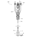
- Spraying of the coating agent containing the highly volatile solvent to be dried onto the inner wall surface of the container C is performed by, for example, a coating apparatus 200 as shown in FIG.
- the container C held by the container holding means H moves to a position below the spray gun 210 and stops, the spray gun 210 is lowered by the vertical drive mechanism 220, and the spray nozzle 211 is inserted into the container C.
- the spray gun 210 is rotated by the rotation drive mechanism 230, and at the same time, the coating agent L is ejected from the tip of the spray nozzle 211 and the spray gun 210 is raised, By spraying the coating agent L from the tip of 211, the coating agent L is sprayed uniformly on the inner wall surface of the container C.
- the container C sprayed with the coating agent L moves to a position below the air current amplification unit 120 of the container internal drying device 100 and stops, while being held by the container holding means H.
- the airflow amplification unit 120 and the gas ejection nozzle 110 are lowered, and as shown in FIG. 2, the airflow amplification unit 120 is configured such that the suction port 123 of the airflow amplification channel 121 is slightly spaced from the mouth C1 of the container C.
- the gas ejection nozzle 110 is further lowered and inserted into the container C.
- the distance between the suction port 123 and the mouth portion C1 of the container C is preferably as narrow as possible within a range in which the container C itself is not deformed or closely adhered to the suction port 123 by negative pressure.
- the timing of starting the ejection of dry air from the gas ejection nozzle 110 and the start of supplying gas to the driving gas supply unit 122 of the airflow amplification unit 120 may be the same as the start of lowering or after the end of lowering. Further, the dry air may be ejected while the gas ejection nozzle 110 moves up and down, or the dry air may be ejected while rotating.
- the drive mechanism can be the same mechanism as the vertical drive mechanism 220 and the rotary drive mechanism 230 of the coating apparatus 200 described above.
- the gas ejection nozzle 110 and the airflow amplification unit 120 are provided together with the spray nozzle 211 of the coating apparatus 200 described above, and after performing the coating process with the spray nozzle 211 in the coating process of the coating agent L, the gas ejection nozzle 110.
- the drying process may be performed by the airflow amplification unit 120.
- supply of the coating agent L with respect to the spray gun 210 may be stopped, and only dry air may be ejected from the spray nozzle 211, and it may function as the gas ejection nozzle 110.
- the container internal drying device 100 is installed with the gas ejection nozzle 110 facing up and down.
- any installation mode of the container internal drying device such as installing the container internal drying device in the horizontal direction may be used.
- the coating agent applied to the container is described as being dried with dry air.
- other liquids such as washing water after washing may be dried.
Abstract
Provided are: a container-interior drying device capable of improving the efficiency of an entire filling line without causing container deformation, capable of shortening drying time, requiring little space for installation thereof, and having a simple configuration; and a container-interior drying method. A container-interior drying device equipped with a gas jet nozzle (110) capable of being inserted into a container interior through a container opening, a suction mechanism (120) capable of facing the container opening, and a gas supply unit (130) for supplying a gas to the gas jet nozzle (110), wherein the gas is sprayed from the gas jet nozzle (110) into the container interior, and the suction mechanism (120) positioned so as to face the container opening sucks the gas out through the container opening.
Description
本発明は、容器内壁面を乾燥する容器内部乾燥装置及び容器内部乾燥方法に関する。
The present invention relates to a container internal drying device and a container internal drying method for drying a container inner wall surface.
一般に、プラスチック容器は、成形が容易で安価に製造できることから各種用途に広く使用されているが、マヨネーズ様食品のような粘稠な内容物を注入した場合、内容物が容器内壁面に付着し易いことから、容器内に内容物を残すことなく使い切ることが難しいという問題があった。
近年、内容物の滑落性を向上させる塗布剤の開発が進んでおり、このような塗布剤を容器内壁面に塗布した場合、容器内壁面の滑落性が向上し、容器内の内容物を容易に使い切ることができることが知られている。
そこで、塗布剤を容器内壁面に均一に塗布するための方策として、特許文献1に示すようなノズルを容器内に挿入し、容器を回転させて塗布剤を噴出することが考えられる。 In general, plastic containers are widely used for various applications because they are easy to mold and can be manufactured at low cost. However, when viscous contents such as mayonnaise-like foods are injected, the contents adhere to the inner wall of the container. Since it was easy, there was a problem that it was difficult to use up without leaving the contents in the container.
In recent years, the development of coating agents that improve the slidability of contents has progressed. When such coating agents are applied to the inner wall surface of a container, the slidability of the inner wall surface of the container is improved and the contents in the container can be easily It is known that it can be used up quickly.
Therefore, as a measure for uniformly applying the coating agent to the inner wall surface of the container, it is conceivable to insert a nozzle as shown in Patent Document 1 into the container and rotate the container to eject the coating agent.
前述のように容器内部に塗布剤を噴出して塗布する場合、揮発性の高い溶剤を含んだ塗布剤の溶液をスプレーした後、十分に溶剤を揮発・乾燥させて容器内壁面に定着させるために、高温のオーブンを通すことが一般的である。
しかしながら、この方法では、充填ライン全体の効率を向上するためには、大型のオーブンが必要で、多額の設備投資や広い設備設置場所が必要となるという問題があった。
また、容器がプラスチック容器などの低い融点の樹脂で構成されている場合、オーブン温度により容器変形の問題が発生したり、温度を下げると乾燥時間が長時間化し充填ライン全体の効率が低下するなどの問題があった。
さらに、容器口部から容器内部に乾燥した気体を噴出して揮発・乾燥を行うことも考えられるが、塗布剤を適用する容器は容器口部の小さいものが多いため、気体の循環を充分に行うことができず、乾燥時間の長時間化は避けられなかった。 When spraying the coating agent inside the container as described above, after spraying the coating agent solution containing a highly volatile solvent, the solvent is sufficiently evaporated and dried to fix it on the inner wall surface of the container. In addition, it is common to pass through a high-temperature oven.
However, in this method, in order to improve the efficiency of the entire filling line, a large-sized oven is required, and there is a problem that a large amount of equipment investment and a wide equipment installation place are required.
In addition, when the container is made of a low melting point resin such as a plastic container, the problem of container deformation may occur due to the oven temperature, or if the temperature is lowered, the drying time will be prolonged and the efficiency of the entire filling line will decrease. There was a problem.
In addition, it may be possible to volatilize and dry by ejecting a dry gas from the container mouth to the inside of the container, but since many containers to which the coating agent is applied have a small container mouth, sufficient circulation of the gas is possible. It could not be carried out, and it was inevitable that the drying time was prolonged.
本発明は、前述した問題点を解決するものであり、簡単な構成で設置スペースが小さく、乾燥時間を短縮することが可能であり、容器変形を生じることなく、充填ライン全体の効率を向上することができる容器内部乾燥装置及び容器内部乾燥方法を提供することを目的とするものである。
The present invention solves the above-described problems, has a simple configuration, requires a small installation space, can shorten the drying time, and improves the efficiency of the entire filling line without causing container deformation. It is an object of the present invention to provide a container internal drying device and a container internal drying method.
本発明に係る容器内部乾燥装置は、容器内壁面を乾燥する容器内部乾燥装置であって、容器口部から容器内部に挿入可能な気体噴出ノズルと、容器口部に対向可能な吸引機構と、前記気体噴出ノズルに気体を供給する気体供給ユニットとを備えたことにより、前記課題を解決するものである。
また、本発明に係る容器内部乾燥方法は、容器内壁面を乾燥する容器内部乾燥方法であって、気体噴出ノズルを容器口部から容器内部に挿入し、前記気体噴出ノズルから容器内部に気体を噴出するとともに、容器口部に対向して配置された吸引機構によって容器口部から気体を吸引することにより、前記課題を解決するものである。 A container internal drying device according to the present invention is a container internal drying device for drying an inner wall surface of a container, a gas ejection nozzle that can be inserted into the container from the container mouth, a suction mechanism that can face the container mouth, By providing a gas supply unit that supplies gas to the gas ejection nozzle, the problem is solved.
Further, the container internal drying method according to the present invention is a container internal drying method for drying the inner wall surface of a container, wherein a gas ejection nozzle is inserted into the container from the container mouth, and gas is introduced into the container from the gas ejection nozzle. The above-described problem is solved by ejecting gas and sucking gas from the container mouth by a suction mechanism disposed opposite to the container mouth.
本請求項1に係る容器内部乾燥装置によれば、容器口部から容器内部に挿入可能な気体噴出ノズルと、容器口部に対向可能な吸引機構と、気体噴出ノズルに気体を供給する気体供給ユニットとを備えたことにより、容易に容器内に乾燥空気等を吹き込み、かつ、吸引機構により容器口部から容器内の気体を吸引することが可能となり、大量の気体を容器内に噴出しても、確実に容器の口部から吸引することができ、容器内での気体の循環を充分に行うことができる。
この結果、簡単な構成で設置スペースが小さく、乾燥時間を短縮することが可能であり、容器変形を生じることなく、充填ライン全体の効率を向上することができる。
また、挿入された気体噴出ノズルによって気体を容器内壁面に吹き付けることも可能となるため、さらに乾燥を促進することができる。 According to the container internal drying apparatus according to the first aspect of the present invention, the gas ejection nozzle that can be inserted into the container from the container mouth, the suction mechanism that can face the container mouth, and the gas supply that supplies the gas to the gas ejection nozzle By providing a unit, it is possible to easily blow dry air or the like into the container and suck the gas in the container from the container mouth portion by the suction mechanism, and a large amount of gas is blown into the container. However, it can be reliably sucked from the mouth of the container, and the gas can be sufficiently circulated in the container.
As a result, the installation space is small with a simple configuration, the drying time can be shortened, and the efficiency of the entire filling line can be improved without causing container deformation.
Moreover, since it becomes possible to spray gas on the inner wall surface of the container by the inserted gas ejection nozzle, drying can be further promoted.
本請求項2に記載の構成によれば、吸引機構が気流増幅ユニットからなり、気流増幅ユニットが、気体供給部と、吸入口、噴出口とを有する気流増幅流路部とを備え、吸入口が容器口部に対向するように配置されていることにより、加圧された気体を使用して吸入口から容器内の気体を吸い出すことが可能となるため、バキューム装置等の設備を必要とせず、より簡単で設置スペースを小さくすることが可能となる。
本請求項3に記載の構成によれば、気体供給ユニットが、気流増幅ユニットの気体供給部に気体を供給することにより、容器内の気体を吸引する独立した駆動源を必要とせず、さらに設置スペースを小さくすることが可能となる。
本請求項4に記載の構成によれば、気体噴出ノズルが、気流増幅ユニットの気流増幅流路部内を貫通するように設けられていることにより、気流増幅ユニットの吸入口が容器口部の全体をカバーするように配置することが可能となり、さらに大量の気体を吸引することができる。
本請求項5に記載の構成によれば、気体噴出ノズルを移動させる移動手段をさらに有することにより、容器を移動させることなく気体噴出ノズルを任意に出し入れすることができるため、既存の容器搬送ライン等に容易に組み込みことが可能となる。
また、容器内で移動しながら気体を噴出することが可能となるため、容器内での気体の循環をさらに充分に行うことができる。 According to the configuration of the second aspect of the present invention, the suction mechanism includes the airflow amplification unit, and the airflow amplification unit includes the gas supply unit, the airflow amplification channel unit including the suction port and the jet port, and the suction port. Is arranged so as to face the container mouth, so that it is possible to suck out the gas in the container from the suction port using pressurized gas, so no equipment such as a vacuum device is required. This makes it possible to simplify and reduce the installation space.
According to the configuration of the third aspect of the present invention, the gas supply unit supplies the gas to the gas supply unit of the airflow amplification unit, so that an independent drive source for sucking the gas in the container is not required, and further installed. Space can be reduced.
According to the configuration of the fourth aspect of the present invention, the gas ejection nozzle is provided so as to penetrate through the airflow amplification flow path portion of the airflow amplification unit, so that the suction port of the airflow amplification unit is the entire container mouth portion. It is possible to arrange so as to cover the gas, and a large amount of gas can be sucked.
According to the configuration of the fifth aspect of the present invention, since the gas ejection nozzle can be arbitrarily taken in and out without moving the container by further having the moving means for moving the gas ejection nozzle, the existing container transport line Etc. can be easily incorporated into the above.
Further, since the gas can be ejected while moving in the container, the gas can be circulated more sufficiently in the container.
本請求項6に係る容器内部乾燥方法によれば、気体噴出ノズルを容器口部から容器内部に挿入し、気体噴出ノズルから容器内部に気体を噴出するとともに、容器口部に対向して配置された吸引機構によって容器口部から気体を吸引することにより、大量の気体を容器内に噴出しても、確実に容器外部に排出することができ、容器内での気体の循環を充分に行うことができる。
この結果、簡単な構成の設備とし、設置スペースも小さくすることができるとともに、乾燥時間を短縮することが可能であり、容器変形を生じることなく、充填ライン全体の効率を向上することができる。
また、挿入された気体噴出ノズルによって気体を容器内壁面に吹き付けることも可能となるため、さらに乾燥を促進することができる。 According to the container internal drying method according to the sixth aspect of the present invention, the gas ejection nozzle is inserted into the container from the container mouth, and the gas is ejected from the gas ejection nozzle into the container, and is disposed opposite to the container mouth. By sucking gas from the container mouth by the suction mechanism, even if a large amount of gas is jetted into the container, it can be reliably discharged outside the container, and the gas can be circulated sufficiently in the container. Can do.
As a result, the equipment can be simply configured, the installation space can be reduced, the drying time can be shortened, and the efficiency of the entire filling line can be improved without causing container deformation.
Moreover, since it becomes possible to spray gas on the inner wall surface of the container by the inserted gas ejection nozzle, drying can be further promoted.
本請求項7に記載の構成によれば、吸引機構が、気体供給部と、吸入口、噴出口とを有する気流増幅流路部とを備えた気流増幅ユニットからなり、気体噴出ノズルに気体を供給して容器内部に気体を噴出するとともに、気流増幅ユニットの気体供給部に気体を供給して容器口部から気体を吸引することにより、バキューム装置等の設備を必要とせず、より簡単な構成の設備とし、設置スペースを小さくすることができる。
According to the configuration of the seventh aspect of the present invention, the suction mechanism includes an airflow amplification unit including a gas supply unit and an airflow amplification channel unit having an inlet and an outlet, and gas is supplied to the gas ejection nozzle. Supplying and ejecting gas inside the container, and supplying gas to the gas supply part of the airflow amplification unit and sucking the gas from the container mouth part eliminates the need for equipment such as a vacuum device, and makes it simpler The installation space can be reduced.
100 ・・・ 容器内部乾燥装置
110 ・・・ 気体噴出ノズル
120 ・・・ 気流増幅ユニット(吸引機構)
121 ・・・ 気流増幅流路部
122 ・・・ 気体供給部
123 ・・・ 吸入口
124 ・・・ 噴出口
130 ・・・ 気体供給ユニット
200 ・・・ 塗布装置
210 ・・・ スプレーガン
211 ・・・ スプレーノズル
220 ・・・ 上下駆動機構
230 ・・・ 回転駆動機構
C ・・・ 容器
C1 ・・・ 口部
L ・・・ 塗布剤
H ・・・ 容器保持手段 DESCRIPTION OFSYMBOLS 100 ... Container inside drying apparatus 110 ... Gas ejection nozzle 120 ... Air flow amplification unit (suction mechanism)
121 ... Airflow amplificationflow path part 122 ... Gas supply part 123 ... Suction port 124 ... Spout port 130 ... Gas supply unit 200 ... Application device 210 ... Spray gun 211 ...・ Spray nozzle 220 ... Vertical drive mechanism 230 ... Rotation drive mechanism C ... Container C1 ... Mouth part L ... Coating agent H ... Container holding means
110 ・・・ 気体噴出ノズル
120 ・・・ 気流増幅ユニット(吸引機構)
121 ・・・ 気流増幅流路部
122 ・・・ 気体供給部
123 ・・・ 吸入口
124 ・・・ 噴出口
130 ・・・ 気体供給ユニット
200 ・・・ 塗布装置
210 ・・・ スプレーガン
211 ・・・ スプレーノズル
220 ・・・ 上下駆動機構
230 ・・・ 回転駆動機構
C ・・・ 容器
C1 ・・・ 口部
L ・・・ 塗布剤
H ・・・ 容器保持手段 DESCRIPTION OF
121 ... Airflow amplification
本発明の一実施形態に係る容器内部乾燥装置100は、図1、図2に示すように、容器Cの口部C1から容器Cの内部に挿入可能な気体噴出ノズル110と、容器Cの口部C1の上方に対向可能な吸引機構である気流増幅ユニット120と、気体噴出ノズル110及び気流増幅ユニット120に気体を供給する気体供給ユニット130とを備えている。
気体噴出ノズル110は、移動手段(図示せず)により上下方向に沿って移動可能に構成され、その下方先端から気体を噴出するよう構成されている。
気流増幅ユニット120は、気体供給部122と、下方に吸入口123、上方に噴出口124とを有する気流増幅流路部121とを備え、特許文献2、3等に示す増幅機構の作用を持つものであり、気体供給部122に供給される気体を気流増幅流路部121の内周に沿って噴出口124側に高速で噴出することにより、吸入口123から気体を吸引して高速、高圧の気体を噴出口124から噴出させるものである。 As shown in FIGS. 1 and 2, a containerinternal drying apparatus 100 according to an embodiment of the present invention includes a gas ejection nozzle 110 that can be inserted into a container C from a mouth C1 of the container C, and a mouth of the container C. An airflow amplification unit 120 that is a suction mechanism that can be opposed to the upper side of the part C1, and a gas supply unit 130 that supplies gas to the gas ejection nozzle 110 and the airflow amplification unit 120 are provided.
Thegas ejection nozzle 110 is configured to be movable in the vertical direction by a moving means (not shown), and is configured to eject gas from its lower end.
Theairflow amplifying unit 120 includes a gas supply unit 122 and an airflow amplifying channel 121 having a suction port 123 on the lower side and a jet port 124 on the upper side. The gas supplied to the gas supply unit 122 is jetted at a high speed along the inner periphery of the airflow amplification flow path unit 121 toward the jet outlet 124 side, whereby the gas is sucked from the suction port 123 to be high-speed and high-pressure. This gas is ejected from the ejection port 124.
気体噴出ノズル110は、移動手段(図示せず)により上下方向に沿って移動可能に構成され、その下方先端から気体を噴出するよう構成されている。
気流増幅ユニット120は、気体供給部122と、下方に吸入口123、上方に噴出口124とを有する気流増幅流路部121とを備え、特許文献2、3等に示す増幅機構の作用を持つものであり、気体供給部122に供給される気体を気流増幅流路部121の内周に沿って噴出口124側に高速で噴出することにより、吸入口123から気体を吸引して高速、高圧の気体を噴出口124から噴出させるものである。 As shown in FIGS. 1 and 2, a container
The
The
また、気流増幅ユニット120は、気体噴出ノズル110の移動手段とは独立した移動手段(図示せず)により上下方向に沿って移動可能に構成され、吸入口123が容器Cの口部C1の上方に対向し、かつ、気体噴出ノズル110が気流増幅流路部121内を貫通するように配置されている。
なお、気流増幅ユニット120は、上下方向に移動しないように固定的に配置されていてもよい。
気体噴出ノズル110及び気流増幅ユニット120の気体供給部122に気体を供給する気体供給ユニット130は、例えば、本実施形態の容器内部乾燥装置100が設置される設置場所における圧縮気体供給源に接続される気体流路のみであってもよく、それぞれに適した圧力、流量とするための調整機構を含んでもよい。
また、容器Cの口部C1から内部の気体を吸引できるものであれば、気流増幅ユニット120に代えて、他の原理の吸引機構を採用してもよい。 Theairflow amplifying unit 120 is configured to be movable in the vertical direction by a moving means (not shown) independent of the moving means for the gas ejection nozzle 110, and the suction port 123 is located above the mouth C1 of the container C. And the gas ejection nozzle 110 is disposed so as to penetrate through the airflow amplification flow path 121.
Theairflow amplification unit 120 may be fixedly arranged so as not to move in the vertical direction.
Thegas supply unit 130 that supplies gas to the gas supply nozzle 122 and the gas supply unit 122 of the airflow amplification unit 120 is connected to, for example, a compressed gas supply source at an installation location where the container internal drying device 100 of the present embodiment is installed. The gas flow path may be only included, and an adjustment mechanism for adjusting the pressure and flow rate suitable for each may be included.
Further, as long as the internal gas can be sucked from the mouth portion C1 of the container C, a suction mechanism of another principle may be employed instead of theairflow amplification unit 120.
なお、気流増幅ユニット120は、上下方向に移動しないように固定的に配置されていてもよい。
気体噴出ノズル110及び気流増幅ユニット120の気体供給部122に気体を供給する気体供給ユニット130は、例えば、本実施形態の容器内部乾燥装置100が設置される設置場所における圧縮気体供給源に接続される気体流路のみであってもよく、それぞれに適した圧力、流量とするための調整機構を含んでもよい。
また、容器Cの口部C1から内部の気体を吸引できるものであれば、気流増幅ユニット120に代えて、他の原理の吸引機構を採用してもよい。 The
The
The
Further, as long as the internal gas can be sucked from the mouth portion C1 of the container C, a suction mechanism of another principle may be employed instead of the
このような容器内部乾燥装置100による、容器内部乾燥方法の一実施形態について説明する。
乾燥すべき揮発性の高い溶剤を含んだ塗布剤の容器Cの内壁面への吹付けは、例えば図3に示すような塗布装置200によって行われる。
容器保持手段Hに保持された容器Cは、スプレーガン210の下方位置に移動して停止し、上下駆動機構220によってスプレーガン210が下降してスプレーノズル211が容器C内に挿入される。
スプレーノズル211が最下方に達したタイミングで、回転駆動機構230によってスプレーガン210を回転させると同時に、スプレーノズル211の先端部から塗布剤Lを噴出し、スプレーガン210を上昇させながら、スプレーノズル211の先端部から塗布剤Lを噴出させることで、容器Cの内壁面に均一に塗布剤Lを吹き付ける。 An embodiment of a container internal drying method using such a containerinternal drying apparatus 100 will be described.
Spraying of the coating agent containing the highly volatile solvent to be dried onto the inner wall surface of the container C is performed by, for example, acoating apparatus 200 as shown in FIG.
The container C held by the container holding means H moves to a position below thespray gun 210 and stops, the spray gun 210 is lowered by the vertical drive mechanism 220, and the spray nozzle 211 is inserted into the container C.
At the timing when thespray nozzle 211 reaches the lowermost position, the spray gun 210 is rotated by the rotation drive mechanism 230, and at the same time, the coating agent L is ejected from the tip of the spray nozzle 211 and the spray gun 210 is raised, By spraying the coating agent L from the tip of 211, the coating agent L is sprayed uniformly on the inner wall surface of the container C.
乾燥すべき揮発性の高い溶剤を含んだ塗布剤の容器Cの内壁面への吹付けは、例えば図3に示すような塗布装置200によって行われる。
容器保持手段Hに保持された容器Cは、スプレーガン210の下方位置に移動して停止し、上下駆動機構220によってスプレーガン210が下降してスプレーノズル211が容器C内に挿入される。
スプレーノズル211が最下方に達したタイミングで、回転駆動機構230によってスプレーガン210を回転させると同時に、スプレーノズル211の先端部から塗布剤Lを噴出し、スプレーガン210を上昇させながら、スプレーノズル211の先端部から塗布剤Lを噴出させることで、容器Cの内壁面に均一に塗布剤Lを吹き付ける。 An embodiment of a container internal drying method using such a container
Spraying of the coating agent containing the highly volatile solvent to be dried onto the inner wall surface of the container C is performed by, for example, a
The container C held by the container holding means H moves to a position below the
At the timing when the
塗布剤Lが吹き付けられた容器Cは、容器保持手段Hに保持されたまま、図1に示すように、容器内部乾燥装置100の気流増幅ユニット120の下方に移動して停止する。
次に、気流増幅ユニット120と気体噴出ノズル110が下降し、図2に示すように、気流増幅ユニット120は、気流増幅流路部121の吸入口123が容器Cの口部C1とわずかに間隔を保つ位置で停止し、気体噴出ノズル110は、さらに下降して容器C内に挿入される。
次いで、気体噴出ノズル110から乾燥空気を噴出させるとともに、気流増幅ユニット120の気体供給部122に気体を供給することで、容器C内の乾燥空気を吸引する。
この時、吸入口123と容器Cの口部C1との間隔は、負圧によって容器C自体が変形したり吸入口123に密着したりしない範囲でなるべく狭いほうがよい。 As shown in FIG. 1, the container C sprayed with the coating agent L moves to a position below the aircurrent amplification unit 120 of the container internal drying device 100 and stops, while being held by the container holding means H.
Next, theairflow amplification unit 120 and the gas ejection nozzle 110 are lowered, and as shown in FIG. 2, the airflow amplification unit 120 is configured such that the suction port 123 of the airflow amplification channel 121 is slightly spaced from the mouth C1 of the container C. The gas ejection nozzle 110 is further lowered and inserted into the container C.
Next, dry air is ejected from thegas ejection nozzle 110, and gas is supplied to the gas supply unit 122 of the airflow amplification unit 120, thereby sucking dry air in the container C.
At this time, the distance between thesuction port 123 and the mouth portion C1 of the container C is preferably as narrow as possible within a range in which the container C itself is not deformed or closely adhered to the suction port 123 by negative pressure.
次に、気流増幅ユニット120と気体噴出ノズル110が下降し、図2に示すように、気流増幅ユニット120は、気流増幅流路部121の吸入口123が容器Cの口部C1とわずかに間隔を保つ位置で停止し、気体噴出ノズル110は、さらに下降して容器C内に挿入される。
次いで、気体噴出ノズル110から乾燥空気を噴出させるとともに、気流増幅ユニット120の気体供給部122に気体を供給することで、容器C内の乾燥空気を吸引する。
この時、吸入口123と容器Cの口部C1との間隔は、負圧によって容器C自体が変形したり吸入口123に密着したりしない範囲でなるべく狭いほうがよい。 As shown in FIG. 1, the container C sprayed with the coating agent L moves to a position below the air
Next, the
Next, dry air is ejected from the
At this time, the distance between the
気体噴出ノズル110からの乾燥空気の噴出開始、及び、気流増幅ユニット120の駆動気体供給部122への気体の供給開始のタイミングは、下降開始と同時でもよく下降終了後であってもよい。
また、気体噴出ノズル110が上下動しながら乾燥空気を噴出してもよく、回転しながら乾燥空気を噴出してもよい。
その際の、駆動機構は、前述の塗布装置200の上下駆動機構220、回転駆動機構230と同様の機構が使用可能である。 The timing of starting the ejection of dry air from thegas ejection nozzle 110 and the start of supplying gas to the driving gas supply unit 122 of the airflow amplification unit 120 may be the same as the start of lowering or after the end of lowering.
Further, the dry air may be ejected while thegas ejection nozzle 110 moves up and down, or the dry air may be ejected while rotating.
In this case, the drive mechanism can be the same mechanism as thevertical drive mechanism 220 and the rotary drive mechanism 230 of the coating apparatus 200 described above.
また、気体噴出ノズル110が上下動しながら乾燥空気を噴出してもよく、回転しながら乾燥空気を噴出してもよい。
その際の、駆動機構は、前述の塗布装置200の上下駆動機構220、回転駆動機構230と同様の機構が使用可能である。 The timing of starting the ejection of dry air from the
Further, the dry air may be ejected while the
In this case, the drive mechanism can be the same mechanism as the
また、気体噴出ノズル110、気流増幅ユニット120を、前述の塗布装置200のスプレーノズル211を併設して、塗布剤Lの塗布工程で、スプレーノズル211で塗布工程を行った後、気体噴出ノズル110、気流増幅ユニット120で乾燥工程を行うようにしてもよい。
さらに、塗布工程を行った後、スプレーガン210に対する塗布剤Lの供給を停止し、乾燥空気のみをスプレーノズル211から噴出させて気体噴出ノズル110として機能させてもよい。 In addition, thegas ejection nozzle 110 and the airflow amplification unit 120 are provided together with the spray nozzle 211 of the coating apparatus 200 described above, and after performing the coating process with the spray nozzle 211 in the coating process of the coating agent L, the gas ejection nozzle 110. The drying process may be performed by the airflow amplification unit 120.
Furthermore, after performing an application | coating process, supply of the coating agent L with respect to thespray gun 210 may be stopped, and only dry air may be ejected from the spray nozzle 211, and it may function as the gas ejection nozzle 110. FIG.
さらに、塗布工程を行った後、スプレーガン210に対する塗布剤Lの供給を停止し、乾燥空気のみをスプレーノズル211から噴出させて気体噴出ノズル110として機能させてもよい。 In addition, the
Furthermore, after performing an application | coating process, supply of the coating agent L with respect to the
前述した実施形態では、気体噴出ノズル110を上下方向に向けて容器内部乾燥装置100を設置したが、水平方向に向けて容器内部乾燥装置を設置する等、容器内部乾燥装置の設置態様は如何なるものでもよい。
また、前述した実施形態では、容器に塗布される塗布剤を乾燥空気により乾燥するものとして説明したが、洗浄後の洗浄水等、他の液体を乾燥するものであってもよい。
さらに、噴出する気体によって加熱、冷却を行ったり、空気以外の特殊な気体を吹き付けることによって他の作用を行わせる用途に使用してもよい。 In the above-described embodiment, the containerinternal drying device 100 is installed with the gas ejection nozzle 110 facing up and down. However, any installation mode of the container internal drying device such as installing the container internal drying device in the horizontal direction may be used. But you can.
In the above-described embodiment, the coating agent applied to the container is described as being dried with dry air. However, other liquids such as washing water after washing may be dried.
Furthermore, you may use for the application which performs another effect | action by heating and cooling with the gas to eject, or spraying special gas other than air.
また、前述した実施形態では、容器に塗布される塗布剤を乾燥空気により乾燥するものとして説明したが、洗浄後の洗浄水等、他の液体を乾燥するものであってもよい。
さらに、噴出する気体によって加熱、冷却を行ったり、空気以外の特殊な気体を吹き付けることによって他の作用を行わせる用途に使用してもよい。 In the above-described embodiment, the container
In the above-described embodiment, the coating agent applied to the container is described as being dried with dry air. However, other liquids such as washing water after washing may be dried.
Furthermore, you may use for the application which performs another effect | action by heating and cooling with the gas to eject, or spraying special gas other than air.
Claims (7)
- 容器内壁面を乾燥する容器内部乾燥装置であって、
容器口部から容器内部に挿入可能な気体噴出ノズルと、
容器口部に対向可能な吸引機構と、
前記気体噴出ノズルに気体を供給する気体供給ユニットとを備えたことを特徴とする容器内部乾燥装置。 A container internal drying device for drying the inner wall surface of the container,
A gas ejection nozzle that can be inserted into the container from the container mouth,
A suction mechanism capable of facing the container mouth,
A container internal drying apparatus comprising: a gas supply unit that supplies gas to the gas ejection nozzle. - 前記吸引機構が、気流増幅ユニットからなり、
前記気流増幅ユニットが、気体供給部と、吸入口、噴出口とを有する気流増幅流路部とを備え、
前記吸入口が、容器口部に対向するように配置されていることを特徴とする請求項1に記載の容器内部乾燥装置。 The suction mechanism comprises an airflow amplification unit,
The airflow amplification unit includes a gas supply section, an airflow amplification flow path section having a suction port and a jet port,
The container internal drying device according to claim 1, wherein the suction port is disposed so as to face the container mouth portion. - 前記気体供給ユニットが、前記気流増幅ユニットの気体供給部に気体を供給することを特徴とする請求項2に記載の容器内部乾燥装置。 The container internal drying device according to claim 2, wherein the gas supply unit supplies gas to a gas supply unit of the airflow amplification unit.
- 前記気体噴出ノズルが、前記気流増幅ユニットの気流増幅流路部内を貫通するように設けられていることを特徴とする請求項2または請求項3に記載の容器内部乾燥装置。 The container internal drying device according to claim 2 or 3, wherein the gas ejection nozzle is provided so as to pass through the inside of the air flow amplification channel portion of the air flow amplification unit.
- 前記気体噴出ノズルを移動させる移動手段をさらに有することを特徴とする請求項1乃至請求項4のいずれかに記載の容器内部乾燥装置。 The container internal drying device according to any one of claims 1 to 4, further comprising moving means for moving the gas ejection nozzle.
- 容器内壁面を乾燥する容器内部乾燥方法であって、
気体噴出ノズルを容器口部から容器内部に挿入し、
前記気体噴出ノズルから容器内部に気体を噴出するとともに、容器口部に対向して配置された吸引機構によって容器口部から気体を吸引することを特徴とする容器内部乾燥方法。 A container internal drying method for drying a container inner wall surface,
Insert the gas ejection nozzle into the container through the container mouth,
A method for drying an inside of a container, wherein gas is ejected from the gas ejection nozzle into the container, and the gas is sucked from the container mouth by a suction mechanism disposed opposite to the container mouth. - 前記吸引機構が、気体供給部と、吸入口、噴出口とを有する気流増幅流路部とを備えた気流増幅ユニットからなり、
前記気体噴出ノズルに気体を供給して容器内部に気体を噴出するとともに、前記気流増幅ユニットの気体供給部に気体を供給して容器口部から気体を吸引することを特徴とする請求項6に記載の容器内部乾燥方法。 The suction mechanism comprises an air current amplification unit including a gas supply unit, and an air current amplification flow path portion having an inlet and a jet port,
The gas is supplied to the gas jet nozzle to jet the gas into the container, and the gas is supplied to the gas supply unit of the airflow amplification unit to suck the gas from the container mouth. The container internal drying method as described.
Priority Applications (4)
| Application Number | Priority Date | Filing Date | Title |
|---|---|---|---|
| CN201580064400.1A CN107003068B (en) | 2014-12-08 | 2015-10-28 | Container internal drier and the internally dry method of container |
| EP15866752.7A EP3232147B1 (en) | 2014-12-08 | 2015-10-28 | Container-interior drying method |
| KR1020177017923A KR20170091129A (en) | 2014-12-08 | 2015-10-28 | Container-interior drying device and container-interior drying method |
| US15/613,524 US10352333B2 (en) | 2014-12-08 | 2017-06-05 | Container-interior drying device and container-interior drying method |
Applications Claiming Priority (2)
| Application Number | Priority Date | Filing Date | Title |
|---|---|---|---|
| JP2014-247881 | 2014-12-08 | ||
| JP2014247881A JP6520088B2 (en) | 2014-12-08 | 2014-12-08 | Container internal drying apparatus and container internal drying method |
Related Child Applications (1)
| Application Number | Title | Priority Date | Filing Date |
|---|---|---|---|
| US15/613,524 Continuation US10352333B2 (en) | 2014-12-08 | 2017-06-05 | Container-interior drying device and container-interior drying method |
Publications (1)
| Publication Number | Publication Date |
|---|---|
| WO2016092963A1 true WO2016092963A1 (en) | 2016-06-16 |
Family
ID=56107158
Family Applications (1)
| Application Number | Title | Priority Date | Filing Date |
|---|---|---|---|
| PCT/JP2015/080364 WO2016092963A1 (en) | 2014-12-08 | 2015-10-28 | Container-interior drying device and container-interior drying method |
Country Status (6)
| Country | Link |
|---|---|
| US (1) | US10352333B2 (en) |
| EP (1) | EP3232147B1 (en) |
| JP (1) | JP6520088B2 (en) |
| KR (1) | KR20170091129A (en) |
| CN (1) | CN107003068B (en) |
| WO (1) | WO2016092963A1 (en) |
Families Citing this family (2)
| Publication number | Priority date | Publication date | Assignee | Title |
|---|---|---|---|---|
| US10914521B2 (en) * | 2019-01-24 | 2021-02-09 | Versum Materials Us, Llc | System and method for drying and analytical testing of containers |
| CN114014246B (en) * | 2021-11-09 | 2023-04-07 | 扬州市天诗美景日化有限公司 | Drying and sterilizing equipment for shampoo bottle |
Citations (8)
| Publication number | Priority date | Publication date | Assignee | Title |
|---|---|---|---|---|
| JPS59212677A (en) * | 1983-05-18 | 1984-12-01 | 大日本印刷株式会社 | Drier for inside of vessel |
| JPH02153846A (en) * | 1988-12-07 | 1990-06-13 | Murase Glass Kk | Production of low-alkali glass container |
| JPH04184000A (en) * | 1990-11-15 | 1992-06-30 | Mitsui Eng & Shipbuild Co Ltd | Ejector for compressive fluid |
| JPH0752555Y2 (en) * | 1993-08-23 | 1995-11-29 | ロザイ工業株式会社 | Can dryer oven |
| JP2000018822A (en) * | 1998-07-03 | 2000-01-18 | Ishikawajima Harima Heavy Ind Co Ltd | Method and device for drying goods |
| JP3389111B2 (en) * | 1998-08-10 | 2003-03-24 | コスモス産業株式会社 | Flexible container bag cleaning device |
| JP2006291941A (en) * | 2005-04-05 | 2006-10-26 | Fukuhara Co Ltd | Method and device for amplifying compressed air quantity |
| US20120312329A1 (en) * | 2010-03-05 | 2012-12-13 | David Hermann-Josef | Tool for Cleaning and/or Drying a Cavity |
Family Cites Families (20)
| Publication number | Priority date | Publication date | Assignee | Title |
|---|---|---|---|---|
| GB123769A (en) * | 1916-09-04 | 1919-10-02 | Emile Louis Alfred Savy | Improvements in Drying Apparatus for Bottles, Jars, Cans or the like Receptacles. |
| US2240364A (en) * | 1939-01-20 | 1941-04-29 | Portland Company | Method of treating the interiors of containers |
| US2509396A (en) * | 1945-03-26 | 1950-05-30 | Carl F Mayer | Drying apparatus for molds |
| US2845934A (en) * | 1953-04-29 | 1958-08-05 | Portland Company | Apparatus for use in cleaning the interiors of barrels |
| JPS584582B2 (en) * | 1978-03-03 | 1983-01-27 | 株式会社大谷電機製作所 | Internal coating equipment |
| JPS5851961A (en) * | 1981-09-21 | 1983-03-26 | Kinzo Fujii | Finishing of paint film on inside wall of pipe and container |
| US4987001A (en) | 1989-02-09 | 1991-01-22 | Nordson Corporation | Method and apparatus for coating the interior surface of hollow, tubular articles |
| FR2645951A1 (en) * | 1989-04-14 | 1990-10-19 | Cgc Entr | Method for drying containers and installation for drying such containers |
| GB2272273A (en) * | 1992-11-10 | 1994-05-11 | Agma Plc | Apparatus for washing and drying containers |
| CN2200168Y (en) * | 1994-05-19 | 1995-06-07 | 陈启松 | Drying machine |
| JP3195209B2 (en) * | 1995-10-13 | 2001-08-06 | 象印マホービン株式会社 | Container inner surface coating method |
| FR2775064B1 (en) * | 1998-02-16 | 2000-05-05 | Sidel Sa | METHOD FOR DRYING HOLLOW BODIES AND DEVICE FOR CARRYING OUT SAID |
| JP2002308231A (en) * | 2001-04-19 | 2002-10-23 | Hokkai Can Co Ltd | Cleaning apparatus for plastic bottle |
| JP2005118683A (en) | 2003-10-17 | 2005-05-12 | Mitsubishi Electric Corp | Coating device and coating method |
| CN2864182Y (en) * | 2005-12-08 | 2007-01-31 | 贾树峰 | Jet draught fan |
| KR101102440B1 (en) * | 2008-07-31 | 2012-01-05 | 이익재 | Different thing removal device |
| CN101592169B (en) * | 2009-05-22 | 2012-10-17 | 汪京涛 | Pneumatic suction fan |
| CN201771874U (en) * | 2010-08-05 | 2011-03-23 | 无锡英威华耀科技有限公司 | Air jetting amplifier |
| CN101968299B (en) * | 2010-10-29 | 2012-05-09 | 武善东 | Method for drying materials by utilizing superheated steam |
| CN203685712U (en) * | 2014-01-03 | 2014-07-02 | 谭文玉 | Air amplifier |
-
2014
- 2014-12-08 JP JP2014247881A patent/JP6520088B2/en active Active
-
2015
- 2015-10-28 EP EP15866752.7A patent/EP3232147B1/en active Active
- 2015-10-28 WO PCT/JP2015/080364 patent/WO2016092963A1/en active Application Filing
- 2015-10-28 KR KR1020177017923A patent/KR20170091129A/en not_active Application Discontinuation
- 2015-10-28 CN CN201580064400.1A patent/CN107003068B/en active Active
-
2017
- 2017-06-05 US US15/613,524 patent/US10352333B2/en active Active
Patent Citations (8)
| Publication number | Priority date | Publication date | Assignee | Title |
|---|---|---|---|---|
| JPS59212677A (en) * | 1983-05-18 | 1984-12-01 | 大日本印刷株式会社 | Drier for inside of vessel |
| JPH02153846A (en) * | 1988-12-07 | 1990-06-13 | Murase Glass Kk | Production of low-alkali glass container |
| JPH04184000A (en) * | 1990-11-15 | 1992-06-30 | Mitsui Eng & Shipbuild Co Ltd | Ejector for compressive fluid |
| JPH0752555Y2 (en) * | 1993-08-23 | 1995-11-29 | ロザイ工業株式会社 | Can dryer oven |
| JP2000018822A (en) * | 1998-07-03 | 2000-01-18 | Ishikawajima Harima Heavy Ind Co Ltd | Method and device for drying goods |
| JP3389111B2 (en) * | 1998-08-10 | 2003-03-24 | コスモス産業株式会社 | Flexible container bag cleaning device |
| JP2006291941A (en) * | 2005-04-05 | 2006-10-26 | Fukuhara Co Ltd | Method and device for amplifying compressed air quantity |
| US20120312329A1 (en) * | 2010-03-05 | 2012-12-13 | David Hermann-Josef | Tool for Cleaning and/or Drying a Cavity |
Also Published As
| Publication number | Publication date |
|---|---|
| US10352333B2 (en) | 2019-07-16 |
| CN107003068A (en) | 2017-08-01 |
| JP6520088B2 (en) | 2019-05-29 |
| EP3232147B1 (en) | 2021-12-08 |
| EP3232147A4 (en) | 2018-08-08 |
| CN107003068B (en) | 2019-06-21 |
| EP3232147A1 (en) | 2017-10-18 |
| US20170268538A1 (en) | 2017-09-21 |
| KR20170091129A (en) | 2017-08-08 |
| JP2016109364A (en) | 2016-06-20 |
Similar Documents
| Publication | Publication Date | Title |
|---|---|---|
| KR102141816B1 (en) | Application method and application device | |
| US10569289B2 (en) | Application apparatus | |
| JP2008174246A (en) | Waterdrop removing apparatus for container, and ring-shaped air nozzle for waterdrop removing apparatus | |
| JP2002308231A (en) | Cleaning apparatus for plastic bottle | |
| TW201513939A (en) | Spiral coating apparatus | |
| WO2016092963A1 (en) | Container-interior drying device and container-interior drying method | |
| KR101064300B1 (en) | Internal coating device for storage case | |
| WO2015170198A1 (en) | A method for coating an inner wall of a container | |
| KR101696826B1 (en) | Apparatus for removing polluter | |
| JP2013071049A (en) | Coating apparatus and coating method using the same | |
| CN105457863A (en) | Oven liner | |
| JP2016109364A5 (en) | ||
| JP2009254928A (en) | Apparatus and method for coating decorative board | |
| JP2004074118A (en) | Chemical-solution applicator | |
| JP2019018139A (en) | Cleaning device | |
| KR102069809B1 (en) | Thin film depositing apparatus and the thin film depositing method using the same | |
| JP3206142U (en) | Sample drying device | |
| KR20190130281A (en) | Machine for coating inside of pipe |
Legal Events
| Date | Code | Title | Description |
|---|---|---|---|
| 121 | Ep: the epo has been informed by wipo that ep was designated in this application |
Ref document number: 15866752 Country of ref document: EP Kind code of ref document: A1 |
|
| NENP | Non-entry into the national phase |
Ref country code: DE |
|
| REEP | Request for entry into the european phase |
Ref document number: 2015866752 Country of ref document: EP |
|
| ENP | Entry into the national phase |
Ref document number: 20177017923 Country of ref document: KR Kind code of ref document: A |