EP3232136A1 - Panneau de chauffage et de ventilation - Google Patents
Panneau de chauffage et de ventilation Download PDFInfo
- Publication number
- EP3232136A1 EP3232136A1 EP17166223.2A EP17166223A EP3232136A1 EP 3232136 A1 EP3232136 A1 EP 3232136A1 EP 17166223 A EP17166223 A EP 17166223A EP 3232136 A1 EP3232136 A1 EP 3232136A1
- Authority
- EP
- European Patent Office
- Prior art keywords
- wall element
- heating
- air
- front wall
- air flow
- Prior art date
- Legal status (The legal status is an assumption and is not a legal conclusion. Google has not performed a legal analysis and makes no representation as to the accuracy of the status listed.)
- Withdrawn
Links
Images

Classifications
-
- F—MECHANICAL ENGINEERING; LIGHTING; HEATING; WEAPONS; BLASTING
- F24—HEATING; RANGES; VENTILATING
- F24S—SOLAR HEAT COLLECTORS; SOLAR HEAT SYSTEMS
- F24S20/00—Solar heat collectors specially adapted for particular uses or environments
- F24S20/60—Solar heat collectors integrated in fixed constructions, e.g. in buildings
- F24S20/67—Solar heat collectors integrated in fixed constructions, e.g. in buildings in the form of roof constructions
-
- H—ELECTRICITY
- H02—GENERATION; CONVERSION OR DISTRIBUTION OF ELECTRIC POWER
- H02S—GENERATION OF ELECTRIC POWER BY CONVERSION OF INFRARED RADIATION, VISIBLE LIGHT OR ULTRAVIOLET LIGHT, e.g. USING PHOTOVOLTAIC [PV] MODULES
- H02S40/00—Components or accessories in combination with PV modules, not provided for in groups H02S10/00 - H02S30/00
- H02S40/40—Thermal components
- H02S40/44—Means to utilise heat energy, e.g. hybrid systems producing warm water and electricity at the same time
-
- F—MECHANICAL ENGINEERING; LIGHTING; HEATING; WEAPONS; BLASTING
- F24—HEATING; RANGES; VENTILATING
- F24S—SOLAR HEAT COLLECTORS; SOLAR HEAT SYSTEMS
- F24S10/00—Solar heat collectors using working fluids
- F24S10/50—Solar heat collectors using working fluids the working fluids being conveyed between plates
- F24S10/502—Solar heat collectors using working fluids the working fluids being conveyed between plates having conduits formed by paired plates and internal partition means
-
- F—MECHANICAL ENGINEERING; LIGHTING; HEATING; WEAPONS; BLASTING
- F24—HEATING; RANGES; VENTILATING
- F24S—SOLAR HEAT COLLECTORS; SOLAR HEAT SYSTEMS
- F24S10/00—Solar heat collectors using working fluids
- F24S10/50—Solar heat collectors using working fluids the working fluids being conveyed between plates
- F24S10/55—Solar heat collectors using working fluids the working fluids being conveyed between plates with enlarged surfaces, e.g. with protrusions or corrugations
-
- F—MECHANICAL ENGINEERING; LIGHTING; HEATING; WEAPONS; BLASTING
- F24—HEATING; RANGES; VENTILATING
- F24S—SOLAR HEAT COLLECTORS; SOLAR HEAT SYSTEMS
- F24S20/00—Solar heat collectors specially adapted for particular uses or environments
- F24S20/60—Solar heat collectors integrated in fixed constructions, e.g. in buildings
- F24S20/66—Solar heat collectors integrated in fixed constructions, e.g. in buildings in the form of facade constructions, e.g. wall constructions
-
- F—MECHANICAL ENGINEERING; LIGHTING; HEATING; WEAPONS; BLASTING
- F24—HEATING; RANGES; VENTILATING
- F24S—SOLAR HEAT COLLECTORS; SOLAR HEAT SYSTEMS
- F24S50/00—Arrangements for controlling solar heat collectors
- F24S50/40—Arrangements for controlling solar heat collectors responsive to temperature
-
- F—MECHANICAL ENGINEERING; LIGHTING; HEATING; WEAPONS; BLASTING
- F24—HEATING; RANGES; VENTILATING
- F24S—SOLAR HEAT COLLECTORS; SOLAR HEAT SYSTEMS
- F24S80/00—Details, accessories or component parts of solar heat collectors not provided for in groups F24S10/00-F24S70/00
- F24S2080/03—Arrangements for heat transfer optimization
- F24S2080/05—Flow guiding means; Inserts inside conduits
-
- Y—GENERAL TAGGING OF NEW TECHNOLOGICAL DEVELOPMENTS; GENERAL TAGGING OF CROSS-SECTIONAL TECHNOLOGIES SPANNING OVER SEVERAL SECTIONS OF THE IPC; TECHNICAL SUBJECTS COVERED BY FORMER USPC CROSS-REFERENCE ART COLLECTIONS [XRACs] AND DIGESTS
- Y02—TECHNOLOGIES OR APPLICATIONS FOR MITIGATION OR ADAPTATION AGAINST CLIMATE CHANGE
- Y02B—CLIMATE CHANGE MITIGATION TECHNOLOGIES RELATED TO BUILDINGS, e.g. HOUSING, HOUSE APPLIANCES OR RELATED END-USER APPLICATIONS
- Y02B10/00—Integration of renewable energy sources in buildings
- Y02B10/20—Solar thermal
-
- Y—GENERAL TAGGING OF NEW TECHNOLOGICAL DEVELOPMENTS; GENERAL TAGGING OF CROSS-SECTIONAL TECHNOLOGIES SPANNING OVER SEVERAL SECTIONS OF THE IPC; TECHNICAL SUBJECTS COVERED BY FORMER USPC CROSS-REFERENCE ART COLLECTIONS [XRACs] AND DIGESTS
- Y02—TECHNOLOGIES OR APPLICATIONS FOR MITIGATION OR ADAPTATION AGAINST CLIMATE CHANGE
- Y02E—REDUCTION OF GREENHOUSE GAS [GHG] EMISSIONS, RELATED TO ENERGY GENERATION, TRANSMISSION OR DISTRIBUTION
- Y02E10/00—Energy generation through renewable energy sources
- Y02E10/40—Solar thermal energy, e.g. solar towers
- Y02E10/44—Heat exchange systems
-
- Y—GENERAL TAGGING OF NEW TECHNOLOGICAL DEVELOPMENTS; GENERAL TAGGING OF CROSS-SECTIONAL TECHNOLOGIES SPANNING OVER SEVERAL SECTIONS OF THE IPC; TECHNICAL SUBJECTS COVERED BY FORMER USPC CROSS-REFERENCE ART COLLECTIONS [XRACs] AND DIGESTS
- Y02—TECHNOLOGIES OR APPLICATIONS FOR MITIGATION OR ADAPTATION AGAINST CLIMATE CHANGE
- Y02E—REDUCTION OF GREENHOUSE GAS [GHG] EMISSIONS, RELATED TO ENERGY GENERATION, TRANSMISSION OR DISTRIBUTION
- Y02E10/00—Energy generation through renewable energy sources
- Y02E10/50—Photovoltaic [PV] energy
-
- Y—GENERAL TAGGING OF NEW TECHNOLOGICAL DEVELOPMENTS; GENERAL TAGGING OF CROSS-SECTIONAL TECHNOLOGIES SPANNING OVER SEVERAL SECTIONS OF THE IPC; TECHNICAL SUBJECTS COVERED BY FORMER USPC CROSS-REFERENCE ART COLLECTIONS [XRACs] AND DIGESTS
- Y02—TECHNOLOGIES OR APPLICATIONS FOR MITIGATION OR ADAPTATION AGAINST CLIMATE CHANGE
- Y02E—REDUCTION OF GREENHOUSE GAS [GHG] EMISSIONS, RELATED TO ENERGY GENERATION, TRANSMISSION OR DISTRIBUTION
- Y02E10/00—Energy generation through renewable energy sources
- Y02E10/60—Thermal-PV hybrids
Definitions
- the invention relates to a heating u. Ventilation panel for installation on building walls and other building surfaces with a rear wall element and a panel outer surface forming a front wall element, according to the preamble of claim 1.
- Heating panels of different design were used in the DE 19902650A1 .
- the DE 199 02 650 A1 describes a roof or facade component for the production of electrical and thermal energy with a transparent cover, which should also be less thermally conductive, in order to reduce the release of the thermal energy of the radiation-absorbing layers to the outside environment.
- the radiation-absorbing layers are located in the region of the rear wall element.
- the FR 2 727 790 describes a solar module with solar cells, which are covered with a glass layer.
- the EP 2 463 601 speaks of a solar heat absorber, which is at least partially translucent.
- the structures described are characterized by a comparatively complex structure, which makes them uneconomical in acquisition and operation.
- the aim of the invention is thus to provide a device for heating, ventilation and drying of building interiors in the context of a self-sufficient and ecological operation, which is characterized structurally by a simple and inexpensive construction and also for subsequent installation on building walls and other Building surfaces is suitable.
- Claim 1 refers to a heating u. Ventilation panel for installation on building walls and other building surfaces with a rear wall element and a panel outer surface forming front wall element, is proposed in the present invention that an air flow generator to ensure an air flow between the front wall element and the inside insulated rear wall element of a suction to a to be heated and ventilated Building interior leading venting connection is provided, wherein the front wall element is made as a black, metallic and opaque surface element and having a connected to the air flow generator photovoltaic power generator.
- the black, opaque surface of the front wall element is heated.
- photovoltaic power generator of the air flow generator is fed simultaneously, which thus operates independently.
- the radiant heat and the convection heat the air flowing through, which is sucked through the heating and ventilation panel by means of the air flow generator, at the back of the front wall element.
- all materials located in the interior are heated by heat conduction of the built-up materials from the front wall element and give in the further this recorded and stored heat back to the air flowing through.
- the subject invention allows the extremely cost-effective production of a heating and ventilation panel, in which the solar radiation is absorbed directly from the front wall element and converted into heat.
- the front wall element is designed for this purpose black, metallic and opaque.
- the functionality of such a device is by no means obvious, but subject to the metallic running and a panel outer surface forming front wall element and a cooling by the usually cold ambient air. Therefore, it has always been proposed in the prior art to cover radiation-absorbing layers with a thermally insulating layer, for example a glass layer.
- a front wall element which is made of a black, metallic and opaque element to produce a hot air flow at temperatures above 40 ° C even at cold ambient temperatures.
- the device according to the invention proves to be effective in European latitudes, especially in winter, when the sun is low accordingly and the solar radiation is incident approximately perpendicular to the arranged on a building wall panel.
- the integrated in the front wall element power generator ensures that the air flow generator is only put into operation when radiation energy is incident and thus is available for a thermal transfer. This ensures that no cold air is blown into the building's interior.
- the electrical energy provided by the generator can be used to blow cool air into the building interior during the night during the night, for example.
- the air flowing through which is sucked by means of air flow generator through the heating and ventilation panel, heated by the radiant heat and convection at the back of the front wall element.
- all materials located in the interior are heated by heat conduction of the built-up materials from the front wall element and give in the further this recorded and stored heat back to the air flowing through.
- air guide surfaces are arranged in the air flow generated by the air flow generator for extending the air path of the air flowing through.
- the air guide surfaces are fitted in the interior of the heating and ventilation panel constructively and thereby thermally coupled to the front wall element. Heating of the front wall element thus also causes heating of the air guide surfaces.
- the air guidance system thus formed extends the airway for longer heat absorption of the air flowing through and increases the surface area for the heat transfer.
- the suction port, through which the air is sucked, and the ventilation port through which the heated air leaves the panel are arranged on the same side of the panel.
- the heating u. Ventilation panel can be carried out on the one hand so that it is at the intake to a leading into the building outside suction bar, or as a recirculation system by the suction is designed as a leading into the heated and ventilated building interior intake manifold.
- FIG. 1 an inventive heating and ventilation panel is shown with a front wall element 2 made of a metallic, opaque material, which is executed on the outside black.
- the front wall panel 2 is made of one piece.
- a suction bar over the entire width of the front wall element 2 is protected from environmental influences.
- service plates 14 openings for servicing or replacement of the air filter located in the lower area, but laterally incorporated, covered on both sides with service plates 14 openings for servicing or replacement of the air filter.
- the filter insert consists of a fabric and is adapted to the shape of the interior of the front wall panel 2 in the oblique suction section. The mesh size is determined by the airborne dust, dirt and small creatures.
- the servicing panels 14 for servicing the air filter (s) are made of the same material as the front wall panel 2.
- a lying in the upper region of the front wall element 2 recess serves as an opening for a power generator 1 (photovoltaic thin-film panel), with the Light rays of the sun is working and thereby generates electricity and installed from behind on the front wall element 2 pending.
- This self-sufficient power generator 1 can be pulled out through a further opening, which has at least the dimensions of the power generator 1, via the rear wall element 8 for service.
- openings can be provided in the front wall panel 2 laterally, upwardly and downwardly, which allow the air overflow between the panels in a lateral series coupling of several heating and ventilation panels.
- the air ducts 3 of the air duct system are made of a metallic, opaque material, which is structurally mounted so that the intake air volume through the entire heating and ventilation panel channeled from the air inlet into the heating and ventilation panel to the exit from the heating and ventilation panel becomes.
- connecting elements 4 In the interior of the heating and ventilation panel are also connecting elements 4 (Z-profile), which connect the front wall element 2 and the rear wall element 8 and thus maintain a constant distance between the two elements.
- the connecting elements 4 are made of a stable, for example metallic material.
- a holder 5 for the power generator 1 hat profiles of stable, for example, metallic material are provided, which are intended to keep the power generator 1 at a constant distance from the front wall element 2. They also serve as decoupling of the power generator 1 to the front wall element. 2
- E-holder 6 are provided, which are made of a canted profile of a stable, such as metallic material and are intended to receive the entire terminal connections.
- the power storage for the night mode / night mode is also mounted on this console.
- an insulation 7 made of polypropylene, polyethylene, or even an elastomer is applied, the heat loss through the Rear wall element 8 prevents.
- the insulation 7 is also applied as protection against condensation on the inside of the rear wall element 8. Furthermore, the insulation 7 also acts as an acoustic insulation against the vibrations that emanate from the air flow generator.
- the rear wall element 8 is made of a metallic, opaque material.
- recesses for the intervention and service of the power supply the air flow generator and the electrical system are provided.
- 8 recesses are provided in the upper region of the rear wall element, in which the thermocouples are incorporated.
- the thermocouples consist of two different metals, which are interconnected so that they give an opening in the upper region of the rear wall element 8 at a certain internal temperature and thus overheating of the heating u. Prevent ventilation panels.
- the heating and ventilation panel is fastened by means of upper retaining elements 9 and lower retaining elements 12 to buildings on the outer side of the building outside to be heated and ventilated building interiors.
- the holding elements 9, 12 are made of a stable, even metallic material, and allow easy installation of the heating and ventilation panel.
- a cover plate 10 In the upper region of the rear wall element 8 is a further opening with a cover plate 10, through which the power connections can be monitored and controlled. Through this opening of the battery pack is also accessible, which is loaded in the sunlight (day mode) on the generator 1, and for the night operating (ventilation mode) supplies the air flow generator with electricity.
- the cover plate 10 is made of the same material as the rear wall element 8. Further, an E-terminal box 11 is provided for the connection profile and the power storage, which may also be made of a stable, metallic material.
- An air flow generator ensures the necessary air flow in the heating and ventilation panel.
- the air flow generator is mounted by means of flange plate from the outside to the rear wall element 8. Depending on customer requirements, this air flow generator can be mounted in three positions. Remaining openings are closed by means of insulated blind covers.
- the ventilation port 13 On the second side of the flange (from the outside) is the ventilation port 13, which is designed as a connecting piece and through which the cleaned and heated air via an air line (flexible or rigid) transported and fed to the building interior.
- the connecting piece consists of plastic or metal and serves to establish the connection between the rear wall element 8 and the air lines (flexible or rigid).
- the heating u. Ventilation panel can also be retrofitted with an optical design frame, according to customer requirements.
- the material of this design frame can be made of all environmentally resistant materials such as wood, metal, glass and plastic or mineral-organic composites.
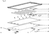
- the embodiment of the Fig. 2 is different from that of Fig. 1 in that instead of the leading into the building outside intake manifold, an intake 15 is provided, which leads into the heated and ventilating building interiors.
- the air to be heated is sucked in the context of a recirculation system from the building interior to be heated, passed through the intake manifold 15 through the heating and ventilation panel and returned as heated air through the ventilation port 13 back to the building interior.
- the air flow generator is preferably arranged in the region of the ventilation connection 13.
- the basic principle of the heating and ventilation panel is based on the physical principle of convection.
- the air to be heated is either as outdoor air (ambient air) via the intake rail ( Fig. 1 ) or as internal air via the intake manifold 15 (FIG. Fig. 2 sucked).
- the intake rail or the intake manifold 15 are provided with an air filter which frees the air flowing through of dirt and other contaminants.
- the sucked and cleaned air is transported to the air flow generator via a size-matched air duct system, which is formed by air guide surfaces 3, which are located between the front wall element 2 and the inside insulated rear wall element 8. Subsequently, the air flow generator presses the cleaned and heated air via the ventilation connection 13 in the rooms to be heated and ventilated.
- the aforementioned ventilation connection 13 represents the interface between the heating and ventilation panel and the building interior.
- the black, matt or glossy and opaque front wall element 2 is heated by the heat rays of the sun. Likewise, the heat gained by the thermal conductivity of the material of the front wall element 2 is transmitted to the inner air guide surfaces 3.
- heat is released to the filter cleaned, flowing air by means of heat radiation.
- the sucked and cleaned by filter air is performed in this process (as described above) through the interior of the heating and ventilation panel and thereby absorbs the heat radiation of the front wall element 2 and the air ducts 3 in the interior of the heating and ventilation panel.
- the insulation 7 applied in the interior to the rear wall element 8 prevents heat loss via the rear wall element 8.
- thermostat device of the invention With a room thermostat device of the invention is controlled. This thermostat switches the switch-on and switch-off temperature. It also shows at the same time the room temperature of the heated or ventilated building interiors. With an on-off switch, the device according to the invention can be switched on and off. About a power storage, the night mode is powered.
- the ventilation and night mode stored in the controller controls the operation independently.
- the device according to the invention is placed on or on building walls, on building roofs, as well as freestanding used. By means of the radiation energy of the sun, the device according to the invention for self-sufficient, independent heating and ventilation device.
Landscapes
- Engineering & Computer Science (AREA)
- Chemical & Material Sciences (AREA)
- Sustainable Development (AREA)
- Physics & Mathematics (AREA)
- Sustainable Energy (AREA)
- Thermal Sciences (AREA)
- Life Sciences & Earth Sciences (AREA)
- Combustion & Propulsion (AREA)
- Mechanical Engineering (AREA)
- General Engineering & Computer Science (AREA)
- Dispersion Chemistry (AREA)
- Building Environments (AREA)
- Finishing Walls (AREA)
- Central Heating Systems (AREA)
Applications Claiming Priority (1)
| Application Number | Priority Date | Filing Date | Title |
|---|---|---|---|
| ATA197/2016A AT518063B1 (de) | 2016-04-14 | 2016-04-14 | Heiz- u. Lüftungspaneel |
Publications (1)
| Publication Number | Publication Date |
|---|---|
| EP3232136A1 true EP3232136A1 (fr) | 2017-10-18 |
Family
ID=58544838
Family Applications (1)
| Application Number | Title | Priority Date | Filing Date |
|---|---|---|---|
| EP17166223.2A Withdrawn EP3232136A1 (fr) | 2016-04-14 | 2017-04-12 | Panneau de chauffage et de ventilation |
Country Status (3)
| Country | Link |
|---|---|
| EP (1) | EP3232136A1 (fr) |
| AT (1) | AT518063B1 (fr) |
| DE (1) | DE202017007356U1 (fr) |
Citations (11)
| Publication number | Priority date | Publication date | Assignee | Title |
|---|---|---|---|---|
| US4378786A (en) * | 1981-02-09 | 1983-04-05 | Comeau Jr Joseph E | Apartment solar heating panel |
| US4557253A (en) * | 1982-11-12 | 1985-12-10 | Atlantic Richfield Company | Solar collector employing conventional siding, and air distribution system therefor |
| WO1994012832A1 (fr) * | 1992-11-30 | 1994-06-09 | Soleco S.A.R.L. | Capteur solaire |
| DE19704794A1 (de) * | 1996-02-12 | 1997-08-14 | Hahn Glasbau | Verkleidung einer Fassade |
| DE19806533A1 (de) * | 1998-02-17 | 1999-08-26 | Henkes | Anordnung zum Aufnehmen von Solarenergie an Gebäuden |
| JP2000160719A (ja) * | 1998-11-30 | 2000-06-13 | Yuichi Yanagi | 建材パネル及び屋根構造並びに床構造 |
| JP2000241031A (ja) * | 1999-02-18 | 2000-09-08 | Tadashi Murai | 太陽熱利用空調ユニット |
| EP2075389A2 (fr) * | 2007-11-30 | 2009-07-01 | Matthew Barnes | Ardoise solaire thermique |
| CN101737963A (zh) * | 2009-12-11 | 2010-06-16 | 江阴美特苏太阳能科技有限公司 | 建筑构件化太阳能空气集热器 |
| CA2733635A1 (fr) * | 2011-03-10 | 2012-09-10 | Mc2 Energie Inc. | Heliocapteur de chauffage a l'air |
| CN102721197A (zh) * | 2012-07-03 | 2012-10-10 | 董永强 | 高效多用途太阳能通风集热器 |
Family Cites Families (4)
| Publication number | Priority date | Publication date | Assignee | Title |
|---|---|---|---|---|
| DE3405176A1 (de) * | 1984-02-14 | 1985-08-22 | Eugen 4600 Dortmund Bauer | Fuer die ausnutzung von sonnenenergie eingerichtete, vorgefertigte aussenwandplatte fuer bauwerke |
| FR2727790A1 (fr) * | 1994-12-02 | 1996-06-07 | Cythelia Sarl | Module solaire hybride photovoltaique et thermique fonctionnant en cogeneration de chaleur et d'energie electrique |
| DE19902650A1 (de) * | 1999-01-24 | 2000-07-27 | Mueller Gerald Patrick | Verfahren zur Gewinnung von Solarenergie durch kombinierte Umwandlung in elektrische und thermische Energie und deren Verwertung sowie Vorrichtungen zur Durchführung des Verfahrens |
| DE102010054394A1 (de) * | 2010-12-07 | 2012-06-14 | Enersearch Gmbh | Solarfassadenelement, Solarfassadensystem |
-
2016
- 2016-04-14 AT ATA197/2016A patent/AT518063B1/de not_active IP Right Cessation
-
2017
- 2017-04-12 DE DE202017007356.0U patent/DE202017007356U1/de not_active Expired - Lifetime
- 2017-04-12 EP EP17166223.2A patent/EP3232136A1/fr not_active Withdrawn
Patent Citations (11)
| Publication number | Priority date | Publication date | Assignee | Title |
|---|---|---|---|---|
| US4378786A (en) * | 1981-02-09 | 1983-04-05 | Comeau Jr Joseph E | Apartment solar heating panel |
| US4557253A (en) * | 1982-11-12 | 1985-12-10 | Atlantic Richfield Company | Solar collector employing conventional siding, and air distribution system therefor |
| WO1994012832A1 (fr) * | 1992-11-30 | 1994-06-09 | Soleco S.A.R.L. | Capteur solaire |
| DE19704794A1 (de) * | 1996-02-12 | 1997-08-14 | Hahn Glasbau | Verkleidung einer Fassade |
| DE19806533A1 (de) * | 1998-02-17 | 1999-08-26 | Henkes | Anordnung zum Aufnehmen von Solarenergie an Gebäuden |
| JP2000160719A (ja) * | 1998-11-30 | 2000-06-13 | Yuichi Yanagi | 建材パネル及び屋根構造並びに床構造 |
| JP2000241031A (ja) * | 1999-02-18 | 2000-09-08 | Tadashi Murai | 太陽熱利用空調ユニット |
| EP2075389A2 (fr) * | 2007-11-30 | 2009-07-01 | Matthew Barnes | Ardoise solaire thermique |
| CN101737963A (zh) * | 2009-12-11 | 2010-06-16 | 江阴美特苏太阳能科技有限公司 | 建筑构件化太阳能空气集热器 |
| CA2733635A1 (fr) * | 2011-03-10 | 2012-09-10 | Mc2 Energie Inc. | Heliocapteur de chauffage a l'air |
| CN102721197A (zh) * | 2012-07-03 | 2012-10-10 | 董永强 | 高效多用途太阳能通风集热器 |
Non-Patent Citations (2)
| Title |
|---|
| DATABASE WPI Section Ch Week 201048, Derwent World Patents Index; Class A88, AN 2010-J09944, XP002773509 * |
| DATABASE WPI Section PQ Week 201306, Derwent World Patents Index; Class Q74, AN 2012-R47395, XP002773510 * |
Also Published As
| Publication number | Publication date |
|---|---|
| AT518063B1 (de) | 2017-07-15 |
| DE202017007356U1 (de) | 2020-11-24 |
| AT518063A4 (de) | 2017-07-15 |
Similar Documents
| Publication | Publication Date | Title |
|---|---|---|
| EP2033231A1 (fr) | Élément solaire avec dispositif de régulation de température | |
| DE202009013639U1 (de) | Niedrigenergiegebäude, insbesondere autarkes Nullenergiehaus | |
| DE102008054099A1 (de) | Anordnung und Verfahrensweise zur Nutzung der Wärmeentstehung an Photovoltaikanlagen innerhalb haustechnischer Anlagen | |
| EP2852727B1 (fr) | Dispositif de refroidissement d'une enceinte | |
| DE102012009909A1 (de) | Klimatisierungsvorrichtung für ein Kraftfahrzeug, Verfahren zu deren Betrieb und Kraftfahrzeug | |
| CH713357A2 (de) | Isolierglas mit Belüftungseinrichtung. | |
| DE202006020354U1 (de) | Temperatur-, Wärme- und/oder Kältebarriere insbesondere für oder in einer Vorrichtung zur Klimatisierung von Gebäuden | |
| DE202013100532U1 (de) | Entlüftungshaube | |
| DE3610767C2 (fr) | ||
| EP3232136A1 (fr) | Panneau de chauffage et de ventilation | |
| WO2009132639A2 (fr) | Bâti | |
| EP2463601A2 (fr) | Élément de fassade solaire, système der fassade solaire | |
| DE3721616A1 (de) | Sonnenwaermeabfuehrung bei fahrzeugen | |
| DE10014924B4 (de) | Verfahren und Vorrichtung zur Versorgung von Gebäuden mit solarer Energie | |
| DE202005004563U1 (de) | Solarkollektor zur Lufterwärmung | |
| DE19733075C1 (de) | Dämmsystem für Gebäudefassaden | |
| DE202012105100U1 (de) | Funktionale Lüftungsfassade mit Lüftungskanälen | |
| DE102012206951A1 (de) | Sonnenkollektor mit variabler Wärmeabgabe | |
| EP4411274B1 (fr) | Dispositif pour obtenir de l'énergie thermique à partir de la lumière solaire et pour stocker l'énergie thermique dans un milieu caloporteur externe | |
| DE102012216823A1 (de) | Thermoanordnung, Verfahren zum Herstellen einer Thermoanordnung und Verfahren zum Montieren einer Thermoanordnung | |
| DE202008014436U1 (de) | Anordnung und Verfahrensweise zur Nutzung der Wärmeentstehung an Photovoltaikanlagen innerhalb haustechnischer Anlagen | |
| DE19816177C1 (de) | Solar-Luft-Kollektor in Fenstersystemtechnik | |
| DE102019210179A1 (de) | Verfahren und Systeme zum Laden eines Kraftfahrzeug-Energiespeichers mittels Lichtenergie | |
| DE10204585B4 (de) | Sonnenkollektor zum vorzugsweisen Betrieb mit gasförmigen Medien | |
| DE102023112011A1 (de) | System zur Erhöhung der Energieeffizienz von Wohn- und Bürogebäuden |
Legal Events
| Date | Code | Title | Description |
|---|---|---|---|
| PUAI | Public reference made under article 153(3) epc to a published international application that has entered the european phase |
Free format text: ORIGINAL CODE: 0009012 |
|
| AK | Designated contracting states |
Kind code of ref document: A1 Designated state(s): AL AT BE BG CH CY CZ DE DK EE ES FI FR GB GR HR HU IE IS IT LI LT LU LV MC MK MT NL NO PL PT RO RS SE SI SK SM TR |
|
| AX | Request for extension of the european patent |
Extension state: BA ME |
|
| 17P | Request for examination filed |
Effective date: 20180403 |
|
| RBV | Designated contracting states (corrected) |
Designated state(s): AL AT BE BG CH CY CZ DE DK EE ES FI FR GB GR HR HU IE IS IT LI LT LU LV MC MK MT NL NO PL PT RO RS SE SI SK SM TR |
|
| 17Q | First examination report despatched |
Effective date: 20190924 |
|
| STAA | Information on the status of an ep patent application or granted ep patent |
Free format text: STATUS: THE APPLICATION IS DEEMED TO BE WITHDRAWN |
|
| 18D | Application deemed to be withdrawn |
Effective date: 20201126 |