EP2463601A2 - Élément de fassade solaire, système der fassade solaire - Google Patents
Élément de fassade solaire, système der fassade solaire Download PDFInfo
- Publication number
- EP2463601A2 EP2463601A2 EP11009662A EP11009662A EP2463601A2 EP 2463601 A2 EP2463601 A2 EP 2463601A2 EP 11009662 A EP11009662 A EP 11009662A EP 11009662 A EP11009662 A EP 11009662A EP 2463601 A2 EP2463601 A2 EP 2463601A2
- Authority
- EP
- European Patent Office
- Prior art keywords
- solar
- building
- air
- insulation
- absorber
- Prior art date
- Legal status (The legal status is an assumption and is not a legal conclusion. Google has not performed a legal analysis and makes no representation as to the accuracy of the status listed.)
- Withdrawn
Links
Images

Classifications
-
- F—MECHANICAL ENGINEERING; LIGHTING; HEATING; WEAPONS; BLASTING
- F24—HEATING; RANGES; VENTILATING
- F24S—SOLAR HEAT COLLECTORS; SOLAR HEAT SYSTEMS
- F24S20/00—Solar heat collectors specially adapted for particular uses or environments
- F24S20/60—Solar heat collectors integrated in fixed constructions, e.g. in buildings
- F24S20/66—Solar heat collectors integrated in fixed constructions, e.g. in buildings in the form of facade constructions, e.g. wall constructions
-
- F—MECHANICAL ENGINEERING; LIGHTING; HEATING; WEAPONS; BLASTING
- F24—HEATING; RANGES; VENTILATING
- F24S—SOLAR HEAT COLLECTORS; SOLAR HEAT SYSTEMS
- F24S10/00—Solar heat collectors using working fluids
- F24S10/25—Solar heat collectors using working fluids having two or more passages for the same working fluid layered in direction of solar-rays, e.g. having upper circulation channels connected with lower circulation channels
-
- F—MECHANICAL ENGINEERING; LIGHTING; HEATING; WEAPONS; BLASTING
- F24—HEATING; RANGES; VENTILATING
- F24S—SOLAR HEAT COLLECTORS; SOLAR HEAT SYSTEMS
- F24S10/00—Solar heat collectors using working fluids
- F24S10/50—Solar heat collectors using working fluids the working fluids being conveyed between plates
-
- F—MECHANICAL ENGINEERING; LIGHTING; HEATING; WEAPONS; BLASTING
- F24—HEATING; RANGES; VENTILATING
- F24S—SOLAR HEAT COLLECTORS; SOLAR HEAT SYSTEMS
- F24S70/00—Details of absorbing elements
- F24S70/60—Details of absorbing elements characterised by the structure or construction
- F24S70/65—Combinations of two or more absorbing elements
-
- Y—GENERAL TAGGING OF NEW TECHNOLOGICAL DEVELOPMENTS; GENERAL TAGGING OF CROSS-SECTIONAL TECHNOLOGIES SPANNING OVER SEVERAL SECTIONS OF THE IPC; TECHNICAL SUBJECTS COVERED BY FORMER USPC CROSS-REFERENCE ART COLLECTIONS [XRACs] AND DIGESTS
- Y02—TECHNOLOGIES OR APPLICATIONS FOR MITIGATION OR ADAPTATION AGAINST CLIMATE CHANGE
- Y02B—CLIMATE CHANGE MITIGATION TECHNOLOGIES RELATED TO BUILDINGS, e.g. HOUSING, HOUSE APPLIANCES OR RELATED END-USER APPLICATIONS
- Y02B10/00—Integration of renewable energy sources in buildings
- Y02B10/20—Solar thermal
-
- Y—GENERAL TAGGING OF NEW TECHNOLOGICAL DEVELOPMENTS; GENERAL TAGGING OF CROSS-SECTIONAL TECHNOLOGIES SPANNING OVER SEVERAL SECTIONS OF THE IPC; TECHNICAL SUBJECTS COVERED BY FORMER USPC CROSS-REFERENCE ART COLLECTIONS [XRACs] AND DIGESTS
- Y02—TECHNOLOGIES OR APPLICATIONS FOR MITIGATION OR ADAPTATION AGAINST CLIMATE CHANGE
- Y02E—REDUCTION OF GREENHOUSE GAS [GHG] EMISSIONS, RELATED TO ENERGY GENERATION, TRANSMISSION OR DISTRIBUTION
- Y02E10/00—Energy generation through renewable energy sources
- Y02E10/40—Solar thermal energy, e.g. solar towers
- Y02E10/44—Heat exchange systems
Definitions
- the present invention relates to an energy-efficient facade insulation system.
- the present invention relates to a solar façade element and a solar façade insulation system that allow for heat storage directly in a building or structure for the efficient use of solar energy and yet a desired facade coloration.
- the heating of inside air basically means the air-conditioning of air, one of the properties of the air (in this case the temperature) being variable. Therefore, although the above discussion refers to the heating of the inside air, which is also the case for the most part, the scope of the invention can also be extended to air humidification / dehumidification and air cooling.
- building within this invention means all residential buildings, commercial buildings or other structures.
- the European patent application EP 0 440 156 discloses a facade element, for inherent temperature control for passive building heating, consisting of a transparent seal and a transparent thermal insulation material and a layer of a material with temperature-dependent translucency (thermotropic material) in front of the building part to be heated, wherein the thermotropic layer parallel to the building part on the inside of the transparent thermal insulation material is arranged, in particular in the front third of the sun-facing side is arranged.
- a second possibility is to provide two layers of thermotropic material in front of and behind the transparent thermal insulation material.
- the facade element can be advantageously used as a solar collector.
- the European patent application EP 1 223 254 discloses a thermal insulation system of a building.
- the present invention relates to a thermal insulation system in which artificial changes due to the needs of the environment are possible.
- An object of this invention is to increase the thermal insulation capacity of the building by surrounding an air layer around the building.
- Another object of the present invention is to propose a thermal insulation system of a building in which an air flow zone is formed between the inner and outer walls by constructing the outer wall at a certain distance from the inner wall.
- An airflow divider divides the airflow zone into a column space according to the direction and facades of the building.
- the European patent EP 1 649 221 discloses a wall-mountable thermal solar thermal storage heat collector having a transparent layer and a solar radiation absorption layer separated from the transparent layer by an air gap. A heat storage layer of phase change material is in intimate contact with the solar radiation absorption layer to facilitate heat transfer. A building board of thermal insulation material is disposed adjacent to the heat storage layer.
- German patent DE 198 00 560 discloses a solar flat collector with an absorber and two transparent panes with two lower heat insulating layers and at least one air inlet opening.
- the channel diameter of the profiled flow channel and the flow channel formed from the inner transparent disc is selected so that the Reynolds number of the channel flow is greater than 5000.
- the invention has for its object to provide a solar facade element and a solar facade system, which ensure improved air conditioning for buildings / structures.
- the object underlying the invention is achieved by a solar facade element with the features of claim 1.
- the solar façade element according to the invention has the advantage that it can be integrated into the insulation of a building so that it replaces the previous insulation of the building or not impaired, and that it can supply the building with fresh air or lead out of the building air, wherein during the air transport a advantageous energy, in particular heat exchange takes place.
- the solar facade element according to the invention for the air conditioning of a building that is mounted / mounted for the air conditioning of the building, in particular on a wall, in particular exterior wall of the building, has at least one ambient solar heat absorber and a building side insulation and an air passage leading through the solar heat absorber and the insulation and to an environment-side opening on the solar heat absorber and a building-side opening on the insulation, wherein the heat absorber is at least partially formed translucent to heat air flowing through the air passage through sunlight or to heat, and wherein the building-side opening of the air passage preferably in a building edge open Recess of the insulation opens.
- the orientation or arrangement / orientation of the components of the solar facade element are divided according to the environment side and the building side.
- a building-side orientation or arrangement is thus an arrangement or orientation of the respective element on or to the building facing side of the solar façade element in the installed state of the building to understand while under an environment-side orientation or arrangement with respect to the facing away from the building and the area of the building facing side is taken.
- a first and a second side could also be mentioned, wherein the first side and the second side are different, in particular opposite, sides of the solar facade element.
- the solar facade element thus has an insulation that can complement the insulation of the building and thus allows complete integration of the solar facade element in an insulation of the building, without the actual insulation of the building is impaired.
- the insulation of the solar facade element therefore corresponds to the insulation of the building in which it is to be integrated.
- the air passage leads from the environment side or from the formed on the first side opening of the solar heat absorber through the solar heat absorber and then through the insulation, in which this purpose a corresponding channel or a corresponding passage is formed to the building side or formed on the second side Opening and thus to the back of the insulation, which is assigned to the building / can be assigned.
- the building can thus be used as a heat storage for the heat emitted by the solar heat absorber - hereinafter also referred to as heat absorber or absorber - to the air, the stored heat when needed also to inflow Fresh air, which has a lower temperature, can be discharged.
- At least one particular environment-side plate or wall or layer of the solar heat absorber is translucent.
- the solar heat absorber preferably has two or more flat plates or walls arranged parallel to one another, which are preferably held at a distance from one another by webs lying therebetween. At least one environment-side plate of these plates is correspondingly translucent or transparent, so that solar radiation reaches the interior of the heat absorber, there to increase a heat input into the air flowing through the heat absorber.
- the surrounding-side opening is formed at one end of the surrounding-side plate.
- a building-side plate of the heat absorber or solar heat absorber is preferably substantially opaque, in particular light-absorbing, so that the solar radiation is completely absorbed in the heat absorber.
- the building-side plate is preferably provided with a light color to increase by reflection the heat input.
- At least one further heat absorber is arranged between the heat absorber and the insulation, wherein the air passage leads sequentially or successively through the heat absorbers.
- the incoming fresh air is thus first passed through the one, the ambient side heat absorber, then ⁇ end by the inner further heat absorber and last by the building side insulation.
- the air passage is preferably formed by corresponding channels in the solar heat absorbers and the insulation.
- a building-side plate or all plates of a heat absorber arranged on the ambient side are designed to be translucent, so that the solar radiation reaches the further heat absorber in order to further heat the air flowing through it.
- the further solar heat absorber is at least substantially opaque or light-absorbing.
- the plates of the further heat absorber are made of an at least substantially opaque material, such as of dark or black plastic.
- the further solar heat absorber is in principle constructed as the solar heat absorber described above, and so far may have two or more plates arranged parallel to each other, which are held by respective (transverse) webs at a distance from each other and held together.
- the translucent walls / plates is provided with a particular translucent color, which in particular on the respective building-side surface of the respective plate of the corresponding solar heat absorber is applied.
- the color is applied so thin that the plate overall translucent, albeit to a small extent, remains.
- the color is selected such that the solar facade element is optically or color matched to the building or to the wall of the insulation of the building to which it is to be attached.
- the respective translucent plate is preferably made of a translucent, translucent material, in particular milky.
- the plate can also be made of a transparent material and obtained by the paint a reduced light transmittance and thus a desired translucency.
- the environmental side plate of the heat absorber is provided on the environment side with a plaster-like translucent or semi-transparent coating.
- the translucency of the coating allows the sunlight in the or the heat absorber, while the plaster-like formation of the coating allows a visually or optically optimal integration of the heat absorber in a building facade, which is provided with a plaster outer layer.
- the coloring of the outer facade and the plaster-like coating of the solar heat absorber may be colored to improve the visual impression.
- the plaster-like coating is made of a synthetic resin with embedded quartz or granules or the like.
- the flow cross-section of the heat absorber is greater than the flow cross-section of the further heat absorber.
- the air passage or a channel of the air passage at least one air conveyor, for example in the form of a ventilation device assigned.
- the air conveyor is attached to the solar facade element.
- the air conveyor is integrated in the insulation or the building side rear side of the insulation and associated with the air passage.
- the solar façade element is designed to be modular for revision purposes and in particular has means for releasable attachment to the building or to the wall of the building.
- the means are at least formed by a frame to which the components of the solar heating element are releasably secured.
- the components of the solar thermal element, in particular the first and / or the second absorber, the insulation and / or optionally provided between the absorbers spacers can be fastened by releasable snap or click connections to the frame so that they can be used successively in the frame or are removable from this.
- the components have inclined cutting patterns, in particular bevels on their outer edge, to ensure a tight connection when inserted.
- the problem underlying the invention is also solved by a solar facade system with the features of claim 11.
- the solar façade system according to the invention with an insulation arranged on a wall, in particular outer wall, of a building has at least one solar façade element integrated in the insulation, as has been described above.
- the insulation of the solar facade element so the building facing and the at least one heat absorber environment side, ie facing the environment of the building or facing away from the building, aligned / arranged.
- the air passage continuing channel or a passage is formed. Since the building wall forms the channel, the advantageous heat exchange already mentioned above takes place between the building or its outer wall and the air flowing through the air passage.
- the channel continues on the wall, in particular between the wall and the insulation of the building, up to a passage opening in the wall to an interior of the building.
- the air is thus preferably channeled through the channel and subsequently into the building.
- the passage opening thus allows the exchange of air between the environment and the building interior, so that fresh air passes through the air passage into the building. This ensures that at appropriate Outside temperatures, in particular sunlight always heated and thus dry fresh air from the outside flows into the building or can flow. At low outside temperatures, for example, at night or in winter, the heat stored in the building is released into the air stream and this is heated by and guided into the building.
- the air passage between the actual insulation of the building and the outer wall of the building is continued, especially if, for example, the through hole is formed away from the solar facade element in the building wall.
- the insulation of the building has a corresponding, especially the building side open-edged recess, which adjoins the solar facade element, in particular at its channel between the insulation and the wall.
- a plurality of solar facade elements are arranged side by side on the housing wall, in particular provided that the channels between insulation and wall of juxtaposed solar facade elements merge into each other, so that the air from a channel in the channel of the next arranged solar façade element passes and there merges with the air streamed through the other solar façade element.
- the plurality of solar facade elements can be arranged both horizontally and vertically next to each other.
- an air conveying device or air circulation device is provided for generating an air flow through the air passage, in particular on and / or in the building.
- This can be the above Air delivery on the solar facade element omitted and the solar facade element can be made simpler, in particular because of this electrical connections and the like are not necessary.
- the air flow control centrally for several solar façade elements Favor by means of only one air conveyor, which is associated with the building, accomplished.
- the air conveyor is associated with the passage opening in the outer wall of the building.
- the solar façade element or façade element and the solar façade system or system make it possible, for example, to convey fresh air into the building through the air passage during the day, whereby the fresh air is heated when the at least one solar heat absorber passes and subsequently releases the heat to the building which releases the heat stores. If fresh air is fed into the building at night or again, the fresh air is heated by the heat stored in the building so that warm and dehumidified air can be transported into the building at night as well.
- a cladding element and system comprising at least one solar heat absorber comprising at least one at least partially translucent layer and / or at least one translucent first and second layer and / or at least one spacer and / or at least one Comprising an insulating block and / or a layer and / or at least one supporting frame and / or at least one air circulation device, wherein a first (solar thermal) absorber (2) preferably has at least three substantially flat plates or arcs, which are preferably substantially parallel to each other by one or a plurality of partitions or webs substantially perpendicular to the three plates or webs Arches are formed to form one or a plurality of channels or passages in which the first plate (14) is optionally covered with an absorbent layer (1); and or a second (solar heat) absorber (3), preferably comprising at least two substantially flat plates or sheets, preferably spaced parallel to one another by one or a plurality of partitions placed substantially perpendicular to the plates or
- the second plate (20) adjacent to the first plate (14) is also preferably provided with an opening (10) at the same end of the first plate, the other end being blocked by a locking device (25).
- the third plate (15) is preferably provided with an opening (21) across the middle part of the length or the height, in which the surface of the third plate (15) exposed in the passage (18) is preferably covered with a brightly colored absorbing layer, and / or wherein the first plate (16) of the second absorber (3) is preferably provided with an opening (22) towards the same end as that of the first absorber opening (9).
- the second plate (17) of the second absorber is preferably provided with an opening (23) transversely across the central portion of the length or height, wherein the second plate (17) is in contact with the insulation (5) which communicates with a passage (6) which is oriented so that the first end of the passage is connected to the opening (23) in the second plate (17), wherein the other end of the passage (6) preferably opens into a passage (13 ), which is formed between the building or the building wall (24) and the insulation (5) or the existing insulation of the building (90) or another solar facade module, and / or wherein, in a preferred operating condition, air flows through the opening (9) of the first and second plates of the first absorber to flow longitudinally or vertically through the passages or channels where the air passes through between the first plate (14 ) and the second plate (20) of the first absorber flows vertically to flow into the channel formed between the first plate (16) of the second plate (17) of the second absorber, otherwise the possible air flow through the spacer (4 ) between the first and second absorber and by the locking
- the air also flows through the opening (23) in the second plate (17) of the second absorber to the passage (6) in the insulating layer to the channel (13) formed between the building wall (24) and the insulation (5), the existing insulation of the building (90) or another solar façade module.
- the solar façade element has in summary an insulation for the building, at least one air passage and at least one solar heat absorber associated with the air passage in order to heat / heat the air flowing through the air passage through solar radiation.
- the solar heat absorber on at least one, at least partially translucent layer which is associated with the air passage or forms these, in particular an at least partially translucent facade element or cover or side wall of the passage, the air that comes from the air passage is at least one between the Insulation and the building wall shaped channel / passage passed.
- another air channel can be provided.
- one side of the wall of the air passage is configured as the at least partially translucent layer.
- the air flowing through the air passage is heated by the solar radiation on the outer surface of the air passage of the solar facade element, whereby the solar radiation partially penetrates into the air passage due to the translucent design of the layer. This will warm the air in the passage.
- Due to the translucent design of the layer it may have a color that adapts to the color of the building so that the solar façade element can be integrated into the building at least substantially unnoticed from the outside.
- the channel which is formed between the insulation and the building wall, allows the heat to be stored directly in the wall or building construction, whereby the stored heat is used for the heating of cold air flowing through the solar façade element or its respective passage or channel when there is no sunshine.
- the solar façade system collectively comprises an insulation attached to a wall of the building and at least one solar façade element as described above integrated into the insulation of the building.
- the channel described in the foregoing preferably extends from the solar façade element further along the building wall between the insulation of the building and the wall and / or between the insulation of another solar façade element as described above. This creates a large channel for receiving the heated air so that the heat can then be stored in the wall or building structure, particularly such that the heat can be used to heat the cold air flowing through at least one duct before the air into the building to warm up the interiors.
- the solar façade system preferably comprises at least one ventilation device or circulation device attached to the duct for operating the solar façade system. Alternatively, the ventilation device can also be attached to the solar facade element.
- the channel has means, for example at least one valve or the like, for selectively directing the air from the façade element or system into the environment of the building.
- the translucent layer of the at least one solar heat absorber preferably has the same color as the outer surface the insulation or the plaster of the building.
- a solar heat absorber or absorber according to the present invention is also called a translucent absorber or solar heat absorber because of its at least partially translucent plate or plates.
- two or more translucent absorbers can be arranged side by side so that the solar radiation can penetrate through each of the translucent absorbers.
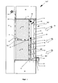
- Fig. 1 shows a sectional front view of one of the embodiments of a solar blind system 75.
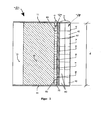
- a plan view of the section is in Fig. 2 shown schematically.
- This embodiment has a solar facade element 70 with a preferably translucent first and second absorber 2, 3 or solar heat absorber, with spacers 4, 30, with Dämmblöcken / layers 5, with a supporting frame 11 and optional with an air circulation device 19 as described below.
- the first absorber 2 has three substantially flat plates or arcs spaced substantially parallel to one another by one or a plurality of partitions 50 (as in FIG Fig. 2 shown) disposed substantially perpendicular to the three plates or sheets to form one or a plurality of channels or passages.
- the first plate 14 is optionally painted or coated with a solar energy absorbing layer 1 made of materials such as paint, quartz, polymer granules, minerals, or a mixture thereof to produce a similar appearance / texture to the building's facade plaster.
- the second absorber 3 has two substantially flat plates or arcs substantially in parallel spaced by one or a plurality of partitions placed substantially perpendicular to the plates or arches.
- the first and second absorbers are spaced apart by means of spacers 4, 30 to form the passage 18.
- the first plate 14 of the first absorber 2 is transverse with an opening 9 (along the depth "d” as in FIG Fig. 2 shown) for the air inlet at one of the ends, which is equipped with a preferred rain protection device 8, which has the form of an "L" or "Z" type component.
- the second plate 20 of the first absorber 2 adjacent to the first plate 14 is also transverse with an opening 10 (along the depth "d” as in FIG Fig. 2 shown) at the same end of the first plate, the other end with a blocking Device is blocked. Depending on the pressure of the air flow, the blocking device may also be removed.
- the third plate 15 of the first absorber 2 is provided with an opening 21 across the depth "d" (shown in FIG Fig. 2 ) in the middle part of the length or height, as in Fig. 1 shown.
- the first plate 16 of the second absorber 3 is provided with an opening 22 in the direction of the same end as that of the first absorber opening 9.
- the second plate 17 of the second absorber 3 is provided with an opening 23 across the depth "d" (shown in FIG Fig. 2 ) in the middle part along the length / height.
- the second plate 17 is in contact with the insulation 5, which is provided with a passage 6, which is aligned so that it adjoins the opening 23.
- the other side of the passage 6 opens into a passage 13 formed between the building construction / building wall 24 (of the building 12) and the insulation 5 or the existing insulation of the building 90 or another solar façade module.
- the area or region 90 above and below the frame 11 is the insulation of the building.
- the area or region to the right or left of the frame is also insulation of the building. Instead of these insulation areas 90, another facade module can be installed.
- at least one or a plurality of such passages, as in Fig. 2 shown, can be formed by partitions 50. Air in the passage 40 is heated due to solar radiation on the plate 14 (the direction is through Reference numeral 50 in FIG Fig. 1 in). This air stream continues to flow to the channel (s) 60 formed between the first plate 16 of the second plate 17 of the second absorber.
- one or a plurality of such channels 60, as in FIG Fig. 2 can be formed by a partition / partition walls 70 between 16 and 17.
- the spacer 4 between the first and second absorbers and the stopper 25 block the air passage as shown in FIG Fig. 2 shown.
- the air continues to flow through the opening 23 into the passage 6 in the insulation and further into the duct or passage 13, between the wall 24 of the building 12 and the insulation 5 or the existing insulation of the building 90 or another Solar façade module is formed.
- the channel or passage 13 uses the surface of the building wall or wall with the building construction to bring the warm or heated air into contact with the building. This allows for partial heat transfer from the heated air to the building structure resulting in efficient use of the significant thermal mass of the building wall or building structure for heat storage purposes.
- the stored heat in the building construction or in the building walls is efficiently used on winter days, where fresh, warm air, which has been heated in the absorbers, is blown directly into the building. On winter nights, fresh air is heated from the heat storage, ie the building construction, and then blown into the building.
- Passage 13 may be of considerable length to heat the building wall or building structure behind the building insulation on all walls, and not just the building wall or building construction directly behind the solar façade.
- the inventive design of the passage 13 allows partial transfer of heat from air or air to the building wall or building structure, thereby facilitating heat storage and allowing the system to be efficient at times of no sun exposure. For this reason, the system of the present invention is extremely versatile.
- the invention is novel and inventive, whereas conventional solar panels and air heating systems merely heat the air and promote the heated air inwardly (into the building or building structure) without storing the heat.
- the other air stream flows through the opening 10 of the second plate 20 and flows vertically through the channel or passage 80 formed between the second plate 20 and the third plate 15.
- one or a plurality of such channels or passages 40 may be formed through the bulkhead or plurality of bulkheads 50.
- the air continues to flow through the opening 21 in the third plate to flow down the passage 18 formed between the first and second absorbers.
- the airway in the upward direction is blocked in this passage by the spacer 30. This air flow continues to flow in an upward direction into the passage 60 of the second absorber. He continues to flow through the opening 23 in the insulation the passage 6 is formed.
- the air then flows into the passage 13, which is optionally provided with an air conveying device or air circulation device 19 in order to supply heated air to the interior of the building.
- the supporting frame 11 is adapted to hold together the assembly of the first absorber which is spaced apart by the spacer, the second absorber and the insulation, thereby forming a module.
- a filter 7 may be mounted in the openings 9, 10. It should be noted that the absorbers are preferably mounted in such a way that exposed ends arise, ie that the top, bottom and side parts of the absorber are spaced from the edge in order to compensate for the thermal expansion or contraction due to varying weather conditions.
- the first absorber 2 thus forms an environment-side absorber or solar heat absorber whose plates 14, 20 and 15 are formed tranlucent.
- the environment-side plate 14 of the absorber 2 is provided with the solar energy absorbing but translucent layer 1, which is in particular designed like a plaster to allow visual integration into the facade of the building.
- Both the plaster-like coating 1 and the translucent plates 14, 20, 15 can be provided with a color which further optimizes the optical effect. If one of the plates 14, 20, 15, as already mentioned above, provided with a color, the color is preferably arranged on the building side surface or side of the respective plate 14, 20, 15 or applied.
- the coating 1 thus serves primarily for aesthetic design and is, in particular, not mirror-like but dull, possibly with a stucco-like structure.
- the building-side outer panel of the environment-side solar heat absorber 2 preferably has a semi-transparent / translucent color, which is applied to its building-side surface.
- the middle plate of the ambient-side absorber 2 is preferably formed without paint.
- the plates 14, 20 and 15 are integrally formed with the webs or partitions 50 and thus made of the same material. By providing the coating 1 on the plate 14 and the color on the building-side outer panel 15, the middle plate 20 remains colorless translucent.
- the absorber 2 is preferably made of a translucent material.
- the translucent ink application on the plate 15 allows solar energy through to the inner or building-side absorber 3. Moreover, by the reflecting and absorbing part of the ink layer on the plate 15, a corresponding heat energy is used in the environment-side absorber 2 and is not rendered useless to the outside, as would be the case with a paint on the outer surface of the plate 14 of the absorber 2.
- the second absorber 3 which thus forms a further absorber or solar heat absorber, which is arranged between the insulation 5 and the absorber 2, is preferably opaque, in particular light-absorbing and preferably has a dark color or is made of a material, in particular plastic, with a dark, especially black color.
- the openings 9 and 10 of the absorber 2 are associated with the environment and thus form together an environmental side opening 71 of the absorber 2.
- the insulation 5 is preferably spaced from the building wall 24 to form the channel or the passage 13 - as shown - or has a building-side open-edged recess.
- the first absorber 2 is designed as a triple-web plate, which has three plates 14, 20, 15, which are connected to one another by webs or partitions 50 and are kept at a distance from each other.
- the absorber 3 may be formed as a triple-land plate, and insofar at least one further plate which is arranged parallel to the plates 16, 17 have.
- the absorber 3 is preferably made of a dark, especially black material in order to ensure the highest possible absorption of the solar energy and thus the highest possible heating of the passing air.
- the building side disposed absorber 3 is preferably formed in one piece.
- the cross section of an absorber 3 thus formed could also be the one in Fig. 2 represented cross-section of the absorber 2 correspond.
- both absorbers 2 and / or 3 may have further correspondingly formed plates and webs or partitions 50.
- FIG. 1 As can be seen, the passage 13 between the insulation 90 of the building 12 and the building wall 24 on, at least up to the air circulation device 19, guided and expediently led into the building, preferably through a corresponding flow opening in the building wall 24 to the interiors of the building 12 to supply with warmed fresh air.
- the solar facade has half the length or height of the invention (as shown in FIG Fig. 1 and 2 ) on.
- the passage 6 leading into the passage 13 is formed at the lower end between the lower frame 11 and the insulating layer 5.
- the first absorber 2 consists of two substantially flat plates or sheets 14 and 15 which are substantially parallel spaced apart from one or a plurality of partitions 50 which are substantially perpendicular to the two plates / sheets.
- a filter 7 may be attached to the opening 9.
- the operation of this embodiment corresponds to the operation of the solar façade, as in Fig. 1 and 2 shown and described.
- the absorber 2 of the embodiment Fig. 3 is thus formed as a double-web plate with two parallel plates 14, 15. The plate 20 is missing so far.
- the flow cross-section of the absorber 2 is greater than the flow cross-section of the absorber 3 in order to ensure an advantageous air flow through the solar facade element.
- the advantageous choice of the flow cross-sections optimizes the ratio between the inner air-flowed surfaces of the building-side absorber to the volume of the current to be heated in this absorber air flow. Due to the larger flow cross-section of the ambient solar heat absorber 2 creates a lower pressure loss when flowing through this absorber 2 and there is a higher insulation / insulation of the heat radiation of the building side absorber 3 by the larger volume of air in the ambient side absorber 2.
- the flow cross-section of the air passage 73 takes a total of the outside to the inside or from the opening 71 to the opening 72 from, so that, for example, the passage 6 has a smaller flow area than the channel 60 and the absorber 3.
- the flow cross section of the passage 13 between the insulation and the building wall 24 in relation to the total flow area of the inner absorber 3 is greater. This results in a lower pressure loss. When flowing through the passage 13, a higher insulation / insulation of the entire system to the building 12 is ensured by the larger amount of air in this passage 13.
- the spacers 4 and 30 are spaced so far from each other that they extend substantially over the entire length or height of the solar facade element, so that an air insulation or insulation between the absorbers 2 and 3 is formed, as in Fig. 3 shown.
- the spacers 34 are dense for this purpose or arranged forming a closed space between the absorbers.
- at least one of the spacers 4 and / or 30 is designed to be permeable to air, and for this purpose has, for example, a corresponding flow opening, so that air can penetrate into the region between the absorbers 2 and 3 and if necessary flow through it can.
- the ambient-side absorber 2 has at least one ventilation opening on the ambient side, in particular at its upper end.
- the air conveyor or air circulation device 19 which is designed in particular as a fan, is not activated and inasmuch as no air flow is actively generated, the warm rising air can escape from the system.
- the at least one ventilation opening preferably has a venting membrane or a different venting valve. The valve can be designed to be automatic and / or controllable.
- At least the absorber 2 arranged on the ambient side is earthed or grounded, for example via a control unit operating the air circulation device 19 or an electrical connection from the absorber 2 to the building wall or its facade, in order to avoid electrostatic charging of the absorber 2 and thereby the danger by electrostatically induced impurities to reduce or avoid.
- the absorber 3 is provided with an insulation, which is designed in particular as the absorber 2, but is closed, so that its inlet and outlet openings are closed and an air flow can not be passed. Instead, the air flow is led to the opening 71 through the air-permeable spacer 4 or 30 in the area between the absorber 3 and the now closed absorber 2, flows through this and passes through the likewise air-permeable spacer 30 or 4 in the absorber 2, to this flow through.
- the absorber 3 forms an ambient-side absorber, which is provided with an insulation on the environment side, which is formed by the closed absorber 2, wherein the air passage 73 first passes through the region between the absorbers 2, 3 and only then through the absorber Absorber 3 and the insulation 5.
- the solar façade In another embodiment of the solar façade, only the first absorber is used (and not the second absorber and not the insulation behind it). This configuration allows a shadow effect in summer and a lower heat effect in winter. In this embodiment, the air flow is only on sunny winter days, but not maintained in the summer. Throughout the year, the embodiment is semi-transparent and the view through the absorber is not completely blocked in this configuration.
- a plurality of passages 13 may be formed between the building wall or the building structure and the insulation.
- the building wall or building construction is used partly as one of the surfaces of the passage 13.
- the air inlet device 9, 10 is mounted in the middle part along the length or height of the first absorber 2.
- the system is used efficiently at very cold temperatures, where the thermal mass of the building wall is heated by the air to passively heat the interior.
- system of the present invention is mounted to the building wall without the use of the frame 11.
- the existing insulation of the building 90 is used to form the passage 13 in which the space between the insulation layer and the building wall is blocked from above, from below and at the sides of the complete facade.
- the space between the wall and the insulation is used in two ways: on the one hand as insulated air passage 13 and on the other hand on warming the building walls by the warm air to to store the energy that has been harnessed by the sun's rays.
- the air circulation device 19 is preferably placed on the north side of the building and the absorbers on the south or west / east side of the building to increase the length of the passage 13 and to use the passage formed due to the existing insulation in that the warm air has maximum contact with the building wall and can store as much energy as possible in the wall (s).
- the absorber 2 is made of polymer-based materials to increase the impact / external pressure resistance.
- the geometry of the solar façade of the present invention is formed as a square shape (viewed from above or from below), i. that is, the lengths of the absorber and the lower side are the same.
- the device has a rectangular or polygonal shape.
- the plates or sheets of the absorber are transparent, translucent, opaque, colored or formed as a combination thereof.
- the plates / sheets of the absorber 2 and / or 3 can be extruded or co-extruded with their partitions in one piece.
- the openings 9 and 10 of the solar facades internal air are supplied.
- the device is adapted such that internal air is circulated when the outside air is dirty and is not suitable for heating purposes in the house or in the system to be heated.
- the use of indoor air has the further advantage of warmer air in winter. This leads to higher final temperatures or earlier use of the system because the air is heated faster. This is needed in extreme winter conditions or when the solar façade system is integrated into an existing heating and air conditioning system.
- the frame and / or the insulating layer may be extruded or expanded in the same foam insulating material to facilitate assembly and integration into the existing insulating materials of the building.
- the foam may consist of polystyrene, polyurethane, polypropylene, polyethylene or other polymers or insulating materials.
- the extruded or expanded foam polymers are combined with various polymers or with plastics, metals, carbon structures, etc. to increase the specific thickness of the frame.
Applications Claiming Priority (1)
| Application Number | Priority Date | Filing Date | Title |
|---|---|---|---|
| DE102010054394A DE102010054394A1 (de) | 2010-12-07 | 2010-12-07 | Solarfassadenelement, Solarfassadensystem |
Publications (2)
| Publication Number | Publication Date |
|---|---|
| EP2463601A2 true EP2463601A2 (fr) | 2012-06-13 |
| EP2463601A3 EP2463601A3 (fr) | 2016-11-02 |
Family
ID=45349349
Family Applications (1)
| Application Number | Title | Priority Date | Filing Date |
|---|---|---|---|
| EP11009662.5A Withdrawn EP2463601A3 (fr) | 2010-12-07 | 2011-12-07 | Élément de fassade solaire, système der fassade solaire |
Country Status (2)
| Country | Link |
|---|---|
| EP (1) | EP2463601A3 (fr) |
| DE (1) | DE102010054394A1 (fr) |
Cited By (2)
| Publication number | Priority date | Publication date | Assignee | Title |
|---|---|---|---|---|
| WO2014177474A1 (fr) * | 2013-04-30 | 2014-11-06 | Commissariat A L'energie Atomique Et Aux Energies Alternatives | Dispositif de chauffage et/ou de rafraichissement a paroi ayant un capteur thermique solaire et un element de stockage d'energie thermique |
| AT518063B1 (de) * | 2016-04-14 | 2017-07-15 | Ernst Martin | Heiz- u. Lüftungspaneel |
Families Citing this family (2)
| Publication number | Priority date | Publication date | Assignee | Title |
|---|---|---|---|---|
| DE102012024427A1 (de) * | 2012-12-14 | 2014-06-18 | Friedrich Hamp | Wärmenutzungssystem und Verwendung eines Passivwärmeabsorbers |
| WO2022038398A1 (fr) * | 2020-08-19 | 2022-02-24 | Masoud Valinejadshoubi | Fenêtre thermique solaire pouvant être fixée |
Citations (4)
| Publication number | Priority date | Publication date | Assignee | Title |
|---|---|---|---|---|
| EP0440156A2 (fr) | 1990-01-29 | 1991-08-07 | Fraunhofer-Gesellschaft Zur Förderung Der Angewandten Forschung E.V. | Elément de façade |
| DE19800560C1 (de) | 1998-01-09 | 1999-04-15 | Thomas Schwertmann | Solarflachkollektor zur Erhitzung von Luft oder anderen gasförmigen Fluiden |
| EP1223254A1 (fr) | 2001-01-16 | 2002-07-17 | Himssen Esco Co., Ltd. | Système d'isolation de bâtiment divisé, suivant l'orientation des façades, en zones à débit vertical d'air contrôlé par ouverture et fermeture |
| EP1649221A1 (fr) | 2003-07-22 | 2006-04-26 | Alberta Research Council, Inc. | Collecteur solaire thermique a capacite de stockage thermique monte sur paroi |
Family Cites Families (21)
| Publication number | Priority date | Publication date | Assignee | Title |
|---|---|---|---|---|
| US4092978A (en) | 1976-08-11 | 1978-06-06 | Levine Richard S | Solar energy collector |
| DE2960617D1 (en) | 1978-04-17 | 1981-11-12 | Cristaleria Espan | Facade of a building provided with at least one solar collector for heating the rooms of this building |
| IT1118902B (it) | 1979-07-27 | 1986-03-03 | Quiroz Gabriella | Collettore solare particolarmente per facchiate di edifici |
| US4495937A (en) | 1981-08-31 | 1985-01-29 | Sunwood Energy Systems, Inc. | Thermal collector and storage system |
| US4426999A (en) | 1982-02-18 | 1984-01-24 | Ramada Energy Systems, Inc. | Solar energy collector |
| AU6149186A (en) | 1985-07-26 | 1987-02-10 | Integrale Energie-Und Umwelttechnik A.G. | Energy-storing facade covering for controlling heat flow |
| DE9306519U1 (fr) | 1993-04-30 | 1993-07-15 | Woelfert, Dietmar, 4150 Krefeld, De | |
| DE19505918A1 (de) * | 1995-02-21 | 1996-08-22 | Karlfried Cost | Sonnenkollektor mit zweifachem Absorber |
| DE19651104A1 (de) | 1996-12-09 | 1998-06-18 | Michael Schumacher | Gebäudefassade |
| NO310636B1 (no) | 1997-06-13 | 2001-07-30 | Harald N Roestvik | Solfangerelement |
| DE19729742A1 (de) * | 1997-07-11 | 1999-01-14 | Zae Bayern | Zuluft-Abluft-Fassadensonnenkollektor |
| DE19902650A1 (de) | 1999-01-24 | 2000-07-27 | Mueller Gerald Patrick | Verfahren zur Gewinnung von Solarenergie durch kombinierte Umwandlung in elektrische und thermische Energie und deren Verwertung sowie Vorrichtungen zur Durchführung des Verfahrens |
| KR100351938B1 (en) | 1999-04-30 | 2002-09-12 | Himssen Esco Co Ltd | Structure of individual ventilation of outer wall of building |
| DE10033535A1 (de) | 2000-07-11 | 2002-01-31 | Ingbuero Dr Ing Harald Schulz | Doppelfassade |
| EP1235042A1 (fr) | 2001-02-14 | 2002-08-28 | Dieter Dipl.-Ing. Mainka | Système de façade de plâtre pour une meilleure utilisation de la chaleur ambiante dans des éléments de construction externes d'accumulateur de chaleur |
| DK200100325U3 (fr) | 2001-12-01 | 2003-01-10 | ||
| PT1538402E (pt) | 2003-12-04 | 2006-12-29 | British Robertson S L U | Colector solar integrado numa fachada |
| JP2009503285A (ja) * | 2005-07-22 | 2009-01-29 | クレケ,エドモンド | 温度、熱及び/又は冷気のバリア |
| DE202006002449U1 (de) * | 2006-02-16 | 2006-10-26 | Buhl, Erich | Solarluftkollektor insbesondere zum Bau von Wintergärten und lichtdurchlässigen Überdachungen |
| DE102007047693A1 (de) | 2007-10-05 | 2009-04-23 | Universität Kassel | Fassaden- oder Dachelement zur Anbringung an einem Gebäude und Verwendung hierfür |
| DE202009006615U1 (de) | 2009-05-05 | 2009-07-16 | Sulfurcell Solartechnik Gmbh | Sonnenenergie nutzendes Fassadenelement und eine das Fassadenelement umfassende Fassade |
-
2010
- 2010-12-07 DE DE102010054394A patent/DE102010054394A1/de not_active Withdrawn
-
2011
- 2011-12-07 EP EP11009662.5A patent/EP2463601A3/fr not_active Withdrawn
Patent Citations (4)
| Publication number | Priority date | Publication date | Assignee | Title |
|---|---|---|---|---|
| EP0440156A2 (fr) | 1990-01-29 | 1991-08-07 | Fraunhofer-Gesellschaft Zur Förderung Der Angewandten Forschung E.V. | Elément de façade |
| DE19800560C1 (de) | 1998-01-09 | 1999-04-15 | Thomas Schwertmann | Solarflachkollektor zur Erhitzung von Luft oder anderen gasförmigen Fluiden |
| EP1223254A1 (fr) | 2001-01-16 | 2002-07-17 | Himssen Esco Co., Ltd. | Système d'isolation de bâtiment divisé, suivant l'orientation des façades, en zones à débit vertical d'air contrôlé par ouverture et fermeture |
| EP1649221A1 (fr) | 2003-07-22 | 2006-04-26 | Alberta Research Council, Inc. | Collecteur solaire thermique a capacite de stockage thermique monte sur paroi |
Cited By (3)
| Publication number | Priority date | Publication date | Assignee | Title |
|---|---|---|---|---|
| WO2014177474A1 (fr) * | 2013-04-30 | 2014-11-06 | Commissariat A L'energie Atomique Et Aux Energies Alternatives | Dispositif de chauffage et/ou de rafraichissement a paroi ayant un capteur thermique solaire et un element de stockage d'energie thermique |
| AT518063B1 (de) * | 2016-04-14 | 2017-07-15 | Ernst Martin | Heiz- u. Lüftungspaneel |
| AT518063A4 (de) * | 2016-04-14 | 2017-07-15 | Ernst Martin | Heiz- u. Lüftungspaneel |
Also Published As
| Publication number | Publication date |
|---|---|
| DE102010054394A1 (de) | 2012-06-14 |
| EP2463601A3 (fr) | 2016-11-02 |
Similar Documents
| Publication | Publication Date | Title |
|---|---|---|
| DE102005006329B4 (de) | Solaranlage | |
| EP1970525B1 (fr) | Elément de façade en verre | |
| DE202009013639U1 (de) | Niedrigenergiegebäude, insbesondere autarkes Nullenergiehaus | |
| DE202006020354U1 (de) | Temperatur-, Wärme- und/oder Kältebarriere insbesondere für oder in einer Vorrichtung zur Klimatisierung von Gebäuden | |
| WO2010028984A2 (fr) | Panneau de façade, système et procédé de production énergétique | |
| EP2463601A2 (fr) | Élément de fassade solaire, système der fassade solaire | |
| DE2624646A1 (de) | Kombiniertes sonnenschutz- und energiegewinnungssystem | |
| EP0005499B1 (fr) | Fenêtre comportant un collecteur d'énergie solaire | |
| EP0028800B1 (fr) | Dispositif pour l'utilisation de la radiation de la chaleur solaire | |
| AT405310B (de) | Bauelement zur wärmedämmung, -isolierung und/oder -regulierung von gebäudehüllen | |
| DE102012104528A1 (de) | Profilsystem zur Befestigung von flexiblen Paneels | |
| WO1999054669A1 (fr) | Cellule solaire comportant un collecteur solaire et des elements accumulateurs | |
| DE3620285A1 (de) | Jalousieanordnung | |
| EP0740764A1 (fr) | Agencement d'isolation thermique et de capteur thermique | |
| DE4444104C1 (de) | Wärmeschutz mit passiver Solarenergienutzung | |
| EP3320275B1 (fr) | Module de fenêtre actif servant à la régulation thermique d'un bâtiment, et procédé | |
| DE102010018632B4 (de) | Solarbetriebener Luftkollektor | |
| DE202007011819U1 (de) | Lüftung an Doppelfassade | |
| WO1999042766A1 (fr) | Dispositif pour capter l'energie solaire sur des batiments | |
| EP0003725B1 (fr) | Fenêtre à double vitrage, aérée dans le sens de la longueur et avec un store à l'intérieur | |
| DE10204585B4 (de) | Sonnenkollektor zum vorzugsweisen Betrieb mit gasförmigen Medien | |
| DE10045029C1 (de) | Vorrichtung zur Nutzung von Solarenergie und zum Anbringen an eine Außenwand- oder Dachfläche eines Gebäudes | |
| EP2891754B1 (fr) | Garde-corps destiné à l'aération d'un local et à l'appoint en chauffage | |
| DE102020131269A1 (de) | Fassadensystem | |
| DE19505918A1 (de) | Sonnenkollektor mit zweifachem Absorber |
Legal Events
| Date | Code | Title | Description |
|---|---|---|---|
| PUAI | Public reference made under article 153(3) epc to a published international application that has entered the european phase |
Free format text: ORIGINAL CODE: 0009012 |
|
| AK | Designated contracting states |
Kind code of ref document: A2 Designated state(s): AL AT BE BG CH CY CZ DE DK EE ES FI FR GB GR HR HU IE IS IT LI LT LU LV MC MK MT NL NO PL PT RO RS SE SI SK SM TR |
|
| AX | Request for extension of the european patent |
Extension state: BA ME |
|
| PUAL | Search report despatched |
Free format text: ORIGINAL CODE: 0009013 |
|
| AK | Designated contracting states |
Kind code of ref document: A3 Designated state(s): AL AT BE BG CH CY CZ DE DK EE ES FI FR GB GR HR HU IE IS IT LI LT LU LV MC MK MT NL NO PL PT RO RS SE SI SK SM TR |
|
| AX | Request for extension of the european patent |
Extension state: BA ME |
|
| RIC1 | Information provided on ipc code assigned before grant |
Ipc: F24J 2/04 20060101AFI20160927BHEP Ipc: F24J 2/20 20060101ALI20160927BHEP |
|
| STAA | Information on the status of an ep patent application or granted ep patent |
Free format text: STATUS: REQUEST FOR EXAMINATION WAS MADE |
|
| 17P | Request for examination filed |
Effective date: 20170502 |
|
| RBV | Designated contracting states (corrected) |
Designated state(s): AL AT BE BG CH CY CZ DE DK EE ES FI FR GB GR HR HU IE IS IT LI LT LU LV MC MK MT NL NO PL PT RO RS SE SI SK SM TR |
|
| STAA | Information on the status of an ep patent application or granted ep patent |
Free format text: STATUS: EXAMINATION IS IN PROGRESS |
|
| 17Q | First examination report despatched |
Effective date: 20190715 |
|
| STAA | Information on the status of an ep patent application or granted ep patent |
Free format text: STATUS: THE APPLICATION IS DEEMED TO BE WITHDRAWN |
|
| 18D | Application deemed to be withdrawn |
Effective date: 20191126 |