EP3231273B1 - Akkumulator - Google Patents
Akkumulator Download PDFInfo
- Publication number
- EP3231273B1 EP3231273B1 EP17164303.4A EP17164303A EP3231273B1 EP 3231273 B1 EP3231273 B1 EP 3231273B1 EP 17164303 A EP17164303 A EP 17164303A EP 3231273 B1 EP3231273 B1 EP 3231273B1
- Authority
- EP
- European Patent Office
- Prior art keywords
- linkage
- carriage
- accumulator
- crop package
- coupled
- Prior art date
- Legal status (The legal status is an assumption and is not a legal conclusion. Google has not performed a legal analysis and makes no representation as to the accuracy of the status listed.)
- Active
Links
Images




Classifications
-
- A—HUMAN NECESSITIES
- A01—AGRICULTURE; FORESTRY; ANIMAL HUSBANDRY; HUNTING; TRAPPING; FISHING
- A01D—HARVESTING; MOWING
- A01D85/00—Arrangements for making or setting stacks
- A01D85/005—Forming groups of bales, e.g. bale sledges
-
- A—HUMAN NECESSITIES
- A01—AGRICULTURE; FORESTRY; ANIMAL HUSBANDRY; HUNTING; TRAPPING; FISHING
- A01D—HARVESTING; MOWING
- A01D90/00—Vehicles for carrying harvested crops with means for selfloading or unloading
- A01D90/02—Loading means
- A01D90/08—Loading means with bale-forming means additionally used for loading; with means for picking-up bales and transporting them into the vehicle
-
- A—HUMAN NECESSITIES
- A01—AGRICULTURE; FORESTRY; ANIMAL HUSBANDRY; HUNTING; TRAPPING; FISHING
- A01F—PROCESSING OF HARVESTED PRODUCE; HAY OR STRAW PRESSES; DEVICES FOR STORING AGRICULTURAL OR HORTICULTURAL PRODUCE
- A01F15/00—Baling presses for straw, hay or the like
- A01F15/08—Details
- A01F15/0875—Discharge devices
- A01F15/0883—Discharge devices for round balers
-
- A—HUMAN NECESSITIES
- A01—AGRICULTURE; FORESTRY; ANIMAL HUSBANDRY; HUNTING; TRAPPING; FISHING
- A01D—HARVESTING; MOWING
- A01D85/00—Arrangements for making or setting stacks
- A01D85/005—Forming groups of bales, e.g. bale sledges
- A01D2085/007—Machines directly attached to a baler
Definitions
- the present disclosure relates to a retraction mechanism for extendable carriages of an agricultural accumulator that supports crop packages.
- US 6 425 235 B1 discloses an agricultural bale accumulator.
- the bale accumulator comprises a load bed extension module including an extension table pivotally connected to a side of a load bed by a hinge and moveable relative to the load bed between a stowed position and an unstowed, bale accumulating, position which is co-planar with a load bed and adjacent to the side of the load bed.
- the agricultural bale accumulator has a first lateral width dimension when the first extension table is in the stowed position to provide a first bale accumulating capacity.
- the agricultural bale accumulator has a second lateral width dimension, greater than the first lateral width dimension, when the first extension table is in the unstowed position to provide a second bale accumulating capacity, greater than the first bale accumulating capacity.
- the invention concerns an accumulator couplable to an agricultural baler and is configured to support crop packages exiting the agricultural baler.
- the accumulator includes a frame having a first end, a second end, and a support structure positioned between the first and the second ends.
- the accumulator also includes a crop package moving assembly moveably coupled to the frame.
- the crop package moving assembly is configured to move a first crop package in a first direction.
- the crop package moving assembly is also configured to move a second crop package in a second direction opposite to the first direction.
- the accumulator further includes a first carriage coupled to the first end of the frame and configured to move relative to the frame between a retracted position and an extended position. The first carriage is configured to support the first crop package that exits the agricultural baler.
- the accumulator also includes a second carriage coupled to the second end of the frame and configured to move relative to the frame between a retracted position and an extended position.
- the second carriage is configured to support the second crop package that exits the agricultural baler.
- the accumulator further includes a retraction linkage coupled to the crop package moving assembly and selectively couplable to the first and second carriages.
- the retraction linkage is configured to move at least one of the first and second carriages from the extended position into the retracted position.
- First and second extension linkages are coupled between the frame and the first and second carriages respectively, the first and second carriages being movable into their extended positions in response to the first and second crop packages engaging the first and second extension linkages.
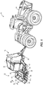
- FIG. 1 illustrates certain agricultural equipment 10 including a tractor 14, a baler 18, and a crop package accumulator 22.
- the baler 18 e.g., a crop packaging system
- the accumulator 22 e.g., a crop package handling system
- the tractor 14 also supplies operational power in the form of hydraulic, electrical, and/or mechanical power to the baler 18 and the accumulator 22.
- the illustrated baler 18 is configured to produce generally cylindrical crop packages, e.g., round bales, from an agricultural field.
- the baler 18 may produce crop packages from hay, corn stalks, and the like.
- the baler 18 may produce generally cuboid crop packages, e.g., square bales.
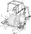
- the baler 18 includes a baler frame 26 to which a baler gate or a crop product barrier 30 is pivotally positionable between a closed position ( FIG. 1 ) and an open position ( FIG. 6 ) by gate hydraulic actuators 34, e.g., hydraulic cylinders.
- the baler gate 30 may translate or slide between the closed position and the open position.
- the illustrated accumulator 22 is coupled to the baler frame 26 such that the baler 18 and the accumulator 22 are supported above a surface or an agricultural field by at least one common axle and associated structure, e.g., wheels 38, although the accumulator can have its own dedicated axles, wheels, and other supporting structural components.
- An accumulator support frame 42 is coupled relative to an accumulator frame 43 about a tube 44 ( FIG. 3 ) defining a rotational axis 46 with the accumulator support frame 42 pivotable relative to the accumulator frame 43 via hydraulic actuators 48 coupled therebetween. Also, the accumulator support frame 42 and the accumulator frame 43 rotate relative to the baler frame 26 about an axis 49.
- a crop package moving assembly 50 that is illustrated as a plate member is oriented substantially perpendicular to the rotational axis 46.
- the moving assembly 50 is slidably coupled to the accumulator support frame 42 in a first direction 54 and a second direction 58.
- the moving assembly 50 is movable in two opposing directions (e.g., left and right).
- the illustrated moving assembly 50 includes a base 62 that extends below a support structure 66 (e.g., platform) of the accumulator support frame 42, and is fixedly coupled to a linkage assembly 70, e.g., a roller chain ( FIG. 3 ).
- the linkage assembly 70 may be another flexible assembly, e.g., a cable, rope, or the like. In further embodiments, the linkage assembly 70 may use a combination of cables, ropes, and/or the like. Both ends 74 of the linkage assembly 70 are fixed relative to crop package hydraulic actuators 78, e.g., hydraulic cylinders operable by the tractor 14, each including a mechanical guide 82 (e.g., a sprocket) that engages the linkage assembly 70.
- crop package hydraulic actuator 78a is coupled to a first sprocket 82a
- a second crop package hydraulic actuator 78b is coupled to a second sprocket 82b.
- the sprockets 82a, 82b uniformly move together in either direction 54, 58 via engagement between the linkage assembly 70 and the sprockets 82a, 82b. Accordingly, extension of the second hydraulic actuator 78b and retraction of the first hydraulic actuator 78a moves the sprocket 82b in a first direction 54, which pulls the linkage assembly 70 and therefore the base 62 and moving assembly 50 in the first direction 54. Extension of the first hydraulic actuator 78a and retraction of the second hydraulic actuator 78b moves the first sprocket 82a in the second direction 58, which pulls the linkage assembly 70 and therefore the base 62 and moving assembly 50 in the second direction 58.
- the crop package hydraulic actuators 78a, 78b may be one hydraulic actuator that is able to move the sprockets 82a, 82b in either direction 54, 58 (e.g., without the linkage assembly 70).
- the bale moving assembly 50 is operable by an electric motor, a cylinder and spring arrangement, pneumatic cylinder(s), or any combination thereof coupled to the accumulator 22.
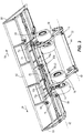
- the illustrated accumulator 22 is also coupled to a first extendable carriage 86 (e.g., a first extendable wing) and a second extendable carriage 90 (e.g., a second extendable wing) both independently moveable generally parallel to the rotational axis 46 between a retracted position ( FIG. 2 ) and an extended position ( FIGS. 3 and 4 ).
- a portion of the extendable carriages 86, 90 is slidably or telescopically receivable within the accumulator support frame 42 by engagement with external and/or internal roller wheels 94 attached to the accumulator support frame 42.
- the extendable carriages 86, 90 may pivot relative to the accumulator support frame 42 (e.g., pivot perpendicular to the rotational axis 46). Each of the extendable carriages 86, 90 is sized and configured to support crop packages that exit the baler 18. In further embodiments, the accumulator 22 may only include one extendable carriage.
- extension linkages 98 are coupled to each side of the accumulator 22 between one of the extendable carriages 86, 90 and the accumulator support frame 42.
- Each illustrated linkage 98 includes a first linkage arm 102 having a top surface 106 pivotably coupled to a second linkage arm 110 having a top surface 114 about a first movable pivot axis 118.
- the first linkage arm 102 is pivotably coupled to the accumulator support frame 42 about a second pivot axis 122
- the second linkage arm 110 is pivotably coupled to the extendable carriages 86, 90 about a third pivot axis 126.
- the extension linkages 98 are designed as generally over-center linkages such that the extension linkages 98 can be rotated into a locked position ( FIG. 4 ). In other embodiments, the extension linkages 98 may not be designed as over-center linkages.
- the pivot axes 118, 122, 126 may be tilted about the rotational axis 46 (e.g., perpendicular to the ground or otherwise not coincident with the direction of travel), and/or the pivot axes 118, 122, 126 may be oriented non-perpendicular to the rotational axis 46.
- a retraction linkage/mechanism 130 is coupled between the moving assembly 50 and the extendable carriages 86, 90 and is configured to independently move the extendable carriages 86, 90 towards the accumulator support frame 42 into the retracted position ( FIG. 2 ).
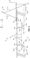
- the retraction linkage 130 includes a first linkage or wedge member 134 and second linkage or wedge members 142a, 142b.
- the first linkage member 134 is positioned between the accumulator support frame 42 and the second linkage members 142a, 142b ( FIG. 5 ).
- the second linkage members 142a, 142b are positioned between the accumulator support frame 42 and the first linkage member 134 ( FIG. 6 ).
- the illustrated first linkage member 134 includes a first end with a first angled surface 136a and a second angled surface 138a and a second end with a first angled surface 136b and a second angled surface 138b.
- the first angled surfaces 136a, 136b generally face towards the moving assembly 50
- the second angled surfaces 138a, 138b generally face towards one of the carriages 86, 90.
- the illustrated first linkage member 134 is attached to the moving assembly 50 for movement therewith in either direction 54, 58.
- the first linkage member 134 is coupled to the base 62 of the moving assembly 50.
- the first linkage member 134 may be coupled to at least one of the sprockets 82 or the linkage assembly 70.
- Biasing members 140a, 140b are coupled between the first linkage member 134 and the accumulator support frame 42 to bias each end of the first linkage member 134 into engagement with the second linkage members 142a, 142b.
- the biasing members 140a, 140b may be coupled to the second linkage members 142a, 142b.
- the biasing members 140a, 140b are coupled to the first linkage member 134 such that the biasing members 140a, 140b remain fixed to the accumulator support frame 42 as the first linkage member 134 moves in either direction 54, 58.
- the biasing members 140a, 140b may be fixed to the first linkage member 134 for movement relative to the accumulator support frame 42.
- the biasing members 140 are coil springs and the coil springs may be adjustable to provide different biasing forces acting on the ends of the first linkage member 134.
- the natural deflection or bending resistance of the first linkage member 134 may function as a biasing force to bias the first linkage member 134.
- the retraction linkage 130 may include two first linkage members 134 with each member 134 extending in one direction 54, 58.
- the illustrated second linkage members 142 each include an end with a first angled surface 144a, 144b and a second angled surface 146a, 146b, and each second linkage member 142a, 142b is configured to move in either direction 54, 58.
- the first angled surfaces 144a, 144b generally face towards one of the carriages 86, 90, and the second angled surfaces 146a, 146b generally face towards the moving assembly 50.
- the second linkage member 142a is associated with the first carriage 86, whereas the second linkage member 142b is associated with the second carriage 90.
- the second linkage member 142a includes an end 150a that is pivotably coupled to the second linkage arm 110 of the extension linkage 98 about a fourth pivot axis 154a.
- the illustrated end 150a is located between the pivot axes 118, 126.
- the second linkage members 142a, 142b are coupled to the extension linkages 98 such that a mechanical advantage is created to pivot the extension linkages 98.
- each of the second linkage members 142a, 142b may be coupled to the first linkage arm 102 of the extension linkage 98.
- the second linkage members 142a, 142b may be coupled to or formed integrally with the extendable carriages 86, 90 for movement therewith.
- Support members 158a, 158b are fixedly coupled to the accumulator support frame 42 and each support member 158a, 158b receives a portion of the second linkage members 142a, 142b to support the second linkage members 142a, 142b when sliding in either direction 54, 58.
- first angled surfaces 136a, 136b, 144a, 144b of linkages 134, 142a, 142b are between about 45 degrees to about 80 degrees (acute) relative to the rotational axis 46 ( FIG. 6 ), and the second angled surfaces 138a, 138b, 146a, 146b of both linkages 134, 142a, 142b are between about 10 degrees to about 45 degrees (acute) relative to the rotational axis 46.
- the carriages 86, 90 are positioned in the retracted position, for ease of transportation and condensed storage of the accumulator 22.
- the accumulator 22 can only support a single crop package 166 on the accumulator support frame 42.
- the extendable carriages 86, 90 can be moved into the extended position by movement of the crop packages.
- the moving assembly 50 moves in either direction 54, 58 to push the first crop package 166 in that direction 54, 58.
- the moving assembly 50 pushes the first crop package 166 in the first direction 54 towards the first extendable carriage 86 to initially abut against the top surface 106 of the first linkage arm 102.
- the crop package 166 pushes against the top surface 106 to pivot the first linkage arm 102 about the second pivot axis 122, thereby concurrently pivoting the second linkage arm 110 about the third pivot axis 126.
- the first extendable carriage 86 is moved into the fully extended position and the first crop package 166 is supported within the first extendable carriage 86 ( FIG. 9 ).
- the extension linkages 98 enable automatic movement of the extendable carriages 86, 90 into the extended position utilizing the movement of the crop packages.
- the retraction linkage 130 independently moves the carriages 86, 90 into the retracted position when a crop package is not supported on the carriages 86, 90 (e.g., a crop package is removed from the carriages 86, 90). Moreover, the illustrated retraction linkage 130 does not retract the carriages 86, 90 if the carriages 86, 90 support a crop package.
- the retraction linkage 130 also moves in the first direction 54.
- the first linkage member 134 moves with the moving assembly 50
- the extension linkage 98 moves the second linkage member 142a in the first direction 54.
- the extension linkage 98 also functions as a motion multiplier to the carriage 86 in that the carriage 86 and the second linkage 142a will extend or move at a faster rate into the extended position than the movement of the moving assembly 50 and the first linkage 134.
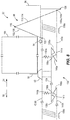
- first angled surfaces 136a, 144a of both linkages 134, 142a initially engage ( FIG. 5 ), and as the first crop package 166 pushes against the extension linkage 98, the engagement or frictional forces between the first angled surfaces 136a, 144a increases against the biasing force of the biasing member 140a.
- the translational movement of the second linkage member 142a relative to the first linkage member 134 will eventually allow at least one of the linkage members 134, 142a to deflect relative to the other linkage member 134, 142a against the biasing force of the biasing member 140a causing relative slip between the first angled surfaces 136a, 144a into a disengaged state ( FIG. 9 ).
- the illustrated biasing member 140a provides a threshold force needed to transition the retraction linkage 130 from the engaged state to the disengaged state or vice versa.
- the first linkage member 134 is further moved via the moving assembly 50 in the first direction 54 such that the second angled surfaces 138a, 146a slide relative to each other for the first angled surfaces 136a, 144a to reengage.
- Such movement of the first linkage member 134 may be considered an intermediate step or lost motion of the first linkage member 134 to position the first linkage member 134 back into engagement with the second linkage member 142a.
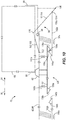
- the linkage members 134, 142a may transition from the engaged state ( FIG. 8 ), to the disengaged state ( FIG. 9 ), and back into the engaged state ( FIG. 10 ) in one continuous motion of the moving assembly 50.
- the first crop package 166 may be removed or dumped onto the agricultural field from the first extendable carriage 86 by pivoting the accumulator support frame 42 about the rotational axis 46. Because the first angle surfaces 136a, 144a are reengaged, an operator of the tractor 14 can then cycle or move the moving assembly 50-and ultimately the retraction linkage 130-in the second direction 58 to move the first extendable carriage 86 via the extension linkage 98 into the retracted position ( FIG. 5 ) without the operator leaving the tractor 14.
- the retraction linkage 130 enables automatic retraction of the extendable carriage 86 utilizing movement of the moving assembly 50.
- a second crop package may be generated within the baler 18 and moved onto the accumulator 22 with the moving assembly 50 moving the second crop package in the second direction 58 before dumping the first crop package 166. Because the weight of the first crop package 166 acts upon the extension linkage 98 (e.g., via engagement with the first crop package 166 and the surface 106), the second linkage member 142a is maintained in the position as illustrated in FIG. 10 when the moving assembly 50 moves in the second direction.
- the weight of the first crop package 166 supported on the first carriage 86 inhibits the first linkage 134 to move the second linkage 142a in the second direction 58 via engagement between the first angled surfaces 136a, 144a (e.g., the first angled surfaces 136a, 144a are allowed to disconnect and slide over each other, as described in detail above).
- the first extendable carriage 86 will not move into the extended position.
- the first linkage member 134 moves in the first direction 54 as the second linkage member 142a remains immobile with the absence of a crop package engaging the extension linkage 98. ( FIG. 5 ).
- enough resistance is provided by the first carriage 86 such that the second angled surfaces 138a, 146a slide over each other if the second angled surface 146a of the second linkage member 142a is positioned between the carriage 86 and the second angled surface 138a of the first linkage member 134.
- the retraction linkage 130 may be coupled to the first extendable carriage 86 so that the first extendable carriage 86 always moves from the retracted position to the extended position upon movement of the moving assembly 50 in the first direction 54. For example, in an instance where the moving assembly 50 moves in the first direction 54 without pushing a crop package towards the first extendable carriage 86, the moving assembly 50 will move the first extendable carriage 86 into the extended position.
- the retraction linkage 130 may be replaced with a pre-loaded biasing member (e.g., pre-loaded torsional spring).
- the pre-loaded biasing member would allow the first crop package 166 to automatically extend the first extendable carriage 86, as described above. The weight of the crop package 166 acts against the pre-loaded biasing member to maintain the crop package 166 supported on the first carriage 86. However, the pre-loaded biasing member automatically retracts the first extendable carriage 86 when the first crop package 166 is dumped or removed from the accumulator 22. In this embodiment, the pre-loaded biasing member acts independently from the movement of the moving assembly 50.
- the retraction linkage 130 may be replaced with hydraulic or electrical actuators coupled to the accumulator support frame 42 and the carriages 86, 90 or the extension linkages 98.
- the hydraulic or electrical actuators operate independently relative to the moving assembly 50. For example, movement of the moving assembly 50 does not require movement of the hydraulic or electrical actuators.
- the extendable carriages 86, 90 may be coupled together by the retraction linkage 130 such that as the first extendable carriage 86 moves into the extended position, the second extendable carriage 90 moves into the retracted position, or vice versa, if no crop packages are present on the carriages 86, 90.
- the retraction linkage 130 may simultaneously retract both carriages 86, 90.
- the extension linkages 98 may be biased into the position illustrated in FIG. 5 to automatically retract the carriages 86, 90 from the extended position when the carriages 86, 90 are not supporting a crop package.
- a torsional spring may be coupled about the first axis 118 to bias the arms 102, 110 towards each other.
- the torsional spring may be concentric with at least one of the axes 118, 122, 126.
Landscapes
- Life Sciences & Earth Sciences (AREA)
- Environmental Sciences (AREA)
- Harvesting Machines For Specific Crops (AREA)
Claims (4)
- Sammler (22), der an eine landwirtschaftliche Ballenpresse (18) koppelbar und dazu ausgelegt ist, Erntegutpakete, die eine landwirtschaftliche Ballenpresse (18) verlassen, zu stützen, wobei der Sammler (22) Folgendes umfasst:einen Rahmen (42), der ein erstes Ende, ein zweites Ende und eine Stützkonstruktion (66) beinhaltet, die zwischen dem ersten und dem zweiten Ende positioniert ist;eine Anordnung (50) zum Bewegen von Erntegutpaketen, die bewegbar an den Rahmen (42) gekoppelt ist, wobei die Anordnung (50) zum Bewegen von Erntegutpaketen dazu ausgelegt ist, ein erstes Erntegutpaket in einer ersten Richtung (54) zu bewegen, wobei die Anordnung (50) zum Bewegen von Erntegutpaketen auch dazu ausgelegt ist, ein zweites Erntegutpaket in einer zweiten Richtung (58) zu bewegen, die der ersten Richtung (54) entgegengesetzt ist;einen ersten Schlitten (86), der mit dem ersten Ende des Rahmens (42) gekoppelt und dazu ausgelegt ist, sich relativ zu dem Rahmen (42) zwischen einer eingefahrenen Position und einer ausgefahrenen Position zu bewegen, wobei der erste Schlitten (86) dazu ausgelegt ist, das erste Erntegutpaket, das die landwirtschaftliche Ballenpresse (18) verlässt, zu stützen;einen zweiten Schlitten (90), der mit dem zweiten Ende des Rahmens (42) gekoppelt und dazu ausgelegt ist, sich relativ zu dem Rahmen (42) zwischen einer eingefahrenen Position und einer ausgefahrenen Position zu bewegen, wobei der zweite Schlitten (90) dazu ausgelegt ist, das zweite Erntegutpaket, das die landwirtschaftliche Ballenpresse (18) verlässt, zu stützen; dadurch gekennzeichnet, dass er Folgendes umfasst:eine Einfahrverbindung (130), die mit der Anordnung (50) zum Bewegen von Erntegutpaketen gekoppelt und wahlweise mit dem ersten Schlitten (86) und dem zweiten Schlitten (90) koppelbar ist, wobei die Einfahrverbindung (130) dazu ausgelegt ist, den ersten Schlitten (86) und/oder den zweiten Schlitten (90) von der ausgefahrenen Position in die eingefahrene Position zu bewegen, und dass er ferner Folgendes umfasst:eine erste Erweiterungsverbindung (98), die zwischen den Rahmen (42) und den ersten Schlitten (86) gekoppelt ist, und eine zweite Erweiterungsverbindung (98), die zwischen den Rahmen (42) und den zweiten Schlitten (90) gekoppelt ist, wobei der erste Schlitten (86) in Reaktion darauf, dass das erste Erntegutpaket in die erste Erweiterungsverbindung (98) eingreift, in die ausgefahrene Position bewegbar ist, und wobei der zweite Schlitten (90) in Reaktion darauf, dass das zweite Erntegutpaket in die zweite Erweiterungsverbindung (98) eingreift, in die ausgefahrene Position bewegbar ist.
- Sammler (22) nach Anspruch 1, wobei die Einfahrverbindung (130) ein erstes Verbindungselement (134) beinhaltet, das mit der Anordnung (50) zum Bewegen von Erntegutpaketen gekoppelt ist, ein zweites Verbindungselement (142a), das mit der ersten Erweiterungsverbindung (98) gekoppelt ist, und ein weiteres zweites Verbindungselement (142b), das mit der zweiten Erweiterungsverbindung (98) gekoppelt ist, und wobei das erste Verbindungselement (134) wahlweise eingreifbar in mindestens eines der zweiten Verbindungselemente (142a, 142b) ist.
- Sammler (22) nach Anspruch 1 oder 2, wobei die Einfahrverbindung (130) dazu ausgelegt ist, in Reaktion darauf, dass sich die Anordnung (50) zum Bewegen von Erntegutpaketen in der zweiten Richtung (58) bewegt, den ersten Schlitten (86) von der ausgefahrenen Position in die eingefahrene Position zu bewegen, und wobei die Einfahrverbindung (130) dazu ausgelegt ist, den zweiten Schlitten (90) in Reaktion darauf, dass sich die Anordnung (50) zum Bewegen von Erntegutpaketen in der ersten Richtung (54) bewegt, den zweiten Schlitten (90) von der ausgefahrenen Position in die eingefahrene Position zu bewegen.
- Sammler (22) nach einem der Ansprüche 1 bis 3, wobei der erste Schlitten (86) in Reaktion darauf, dass das erste Erntegutpaket von dem ersten Schlitten (86) gestützt wird und sich die Anordnung (50) zum Bewegen von Erntegutpaketen in die zweite Richtung (58) bewegt, in der ausgefahrenen Position bleibt, und wobei der zweite Schlitten (90) in Reaktion darauf, dass das zweite Erntegutpaket von dem zweiten Schlitten (90) gestützt wird und sich die Anordnung (50) zum Bewegen von Erntegutpaketen in die erste Richtung (54) bewegt, in der ausgefahrenen Position bleibt.
Applications Claiming Priority (2)
| Application Number | Priority Date | Filing Date | Title |
|---|---|---|---|
| US201662320154P | 2016-04-08 | 2016-04-08 | |
| US15/427,987 US10212886B2 (en) | 2016-04-08 | 2017-02-08 | Retraction mechanism for extendable carriages of an agricultural accumulator |
Publications (2)
| Publication Number | Publication Date |
|---|---|
| EP3231273A1 EP3231273A1 (de) | 2017-10-18 |
| EP3231273B1 true EP3231273B1 (de) | 2018-12-05 |
Family
ID=58464427
Family Applications (1)
| Application Number | Title | Priority Date | Filing Date |
|---|---|---|---|
| EP17164303.4A Active EP3231273B1 (de) | 2016-04-08 | 2017-03-31 | Akkumulator |
Country Status (2)
| Country | Link |
|---|---|
| US (2) | US10212886B2 (de) |
| EP (1) | EP3231273B1 (de) |
Families Citing this family (7)
| Publication number | Priority date | Publication date | Assignee | Title |
|---|---|---|---|---|
| AU2013249982B2 (en) * | 2012-04-20 | 2016-07-28 | Forage Company B.V. | Continuous bale forming apparatus with a pivotal bale supporting construction |
| US10918020B2 (en) | 2015-09-30 | 2021-02-16 | Deere & Company | Baler and accumulator control system |
| US10517219B2 (en) * | 2016-04-08 | 2019-12-31 | Deere & Company | Mechanical linkage for agricultural accumulator including extendable carriages |
| US10212886B2 (en) * | 2016-04-08 | 2019-02-26 | Deere & Company | Retraction mechanism for extendable carriages of an agricultural accumulator |
| US10653067B1 (en) | 2019-05-21 | 2020-05-19 | Deere & Company | Crop package accumulator |
| US11240967B2 (en) | 2019-05-21 | 2022-02-08 | Deere & Company | Control system for a crop package accumulator and method of using same |
| US11140827B2 (en) | 2020-01-17 | 2021-10-12 | Cnh Industrial Canada, Ltd. | Round bale aligner and accumulator |
Family Cites Families (43)
| Publication number | Priority date | Publication date | Assignee | Title |
|---|---|---|---|---|
| US3163302A (en) | 1962-04-02 | 1964-12-29 | Daffin Company | Hay bale accumulator |
| DE2851117A1 (de) | 1978-11-25 | 1980-06-12 | Karl Speidel | Sammel- und ablegevorrichtung fuer pressballen |
| US4310275A (en) | 1979-05-23 | 1982-01-12 | Hoelscher Darrel G | Tilting platform hay bale accumulator |
| GB2106830A (en) | 1981-10-01 | 1983-04-20 | Russell S | Bale accumulators |
| AU568143B2 (en) | 1983-09-14 | 1987-12-17 | Hills, A.F. | Trailer to arrange hay bales |
| US4549840A (en) | 1984-04-02 | 1985-10-29 | Jan Ansbjer | Self-loading carriage for round bales |
| US4789289A (en) * | 1986-12-23 | 1988-12-06 | Wilson Leon R | Bale loader, handler and feeder |
| GB8711812D0 (en) | 1987-05-19 | 1987-06-24 | Stone A F | Bale accumulator |
| US4844675A (en) | 1987-06-01 | 1989-07-04 | Ford New Holland, Inc. | Bale accumulator with automatic control |
| US5211345A (en) | 1988-03-11 | 1993-05-18 | Charles Siebenga | Large bale handling apparatus |
| DE3853069T2 (de) | 1988-07-12 | 1995-06-29 | Ford New Holland Nv | Ballensammler. |
| PL158422B1 (en) | 1988-09-15 | 1992-09-30 | Politechnika Poznanska | Machine for rolling hay and combine harvester straw bales |
| IL89318A0 (en) | 1989-02-17 | 1989-09-10 | Kofman Anatoli | Vehicle locking device |
| FR2679410A1 (fr) * | 1991-07-22 | 1993-01-29 | Doucet Freres Sa | Porte balles aligneur groupeur. |
| US5180271A (en) * | 1991-10-16 | 1993-01-19 | Farden David O | Cylindrical bale transport device |
| GB2297944B (en) | 1995-02-18 | 1998-09-02 | David Richard Leech | Bale accumulator |
| US5842823A (en) | 1995-12-13 | 1998-12-01 | Gehl Company | Bale-accumulating trailer |
| FR2751506B1 (fr) | 1996-07-26 | 1998-09-11 | Socomep Sa | Dispositif groupeur de bottes de paille ou de foin parallelepipediques delivrees par une presse |
| US6425235B1 (en) | 1997-09-02 | 2002-07-30 | Phillip G. Spaniol | Agricultural bale accumulator having a load bed extension module |
| NL1008400C2 (nl) | 1998-02-24 | 1999-08-25 | Meijer Ten Post Beheer B V | Balenverzamelaar met draaibaar achterste rollenbedgedeelte. |
| ATE221307T1 (de) | 1998-08-03 | 2002-08-15 | Ford New Holland Nv | Vorrichtung zum umwickeln einer rundballe |
| CA2709397A1 (en) | 1998-10-23 | 2000-05-04 | Farm Technology L.L.C. | Agricultural bale accumulator and method therefor |
| US6053685A (en) | 1999-02-22 | 2000-04-25 | Tomchak; Frank | Bale accumulator |
| US6892632B1 (en) | 2001-08-10 | 2005-05-17 | Gehl Company | Jointed bale kicker for a round baler |
| US6537008B1 (en) * | 2001-11-06 | 2003-03-25 | Clay A. Haring | Multi-use farm trailer |
| JP2003143927A (ja) | 2001-11-15 | 2003-05-20 | Rooru Create:Kk | ロールキャッチトレ−ラ |
| CA2391055C (en) | 2002-06-20 | 2007-08-21 | Phiber Manufacturing Inc. | Bale accumulator |
| DE10254954A1 (de) | 2002-11-26 | 2004-06-03 | Deere & Company, Moline | Ballenentladevorrichtung einer Rundballenpresse |
| AU2003262343A1 (en) | 2003-11-18 | 2005-06-02 | Apps Family Holdings Pty Ltd | A Towable Bale Accumulator |
| DE102004027895A1 (de) | 2004-06-09 | 2006-01-05 | Claas Selbstfahrende Erntemaschinen Gmbh | Ballenablagesystem |
| US7963734B2 (en) | 2008-08-14 | 2011-06-21 | Ernest Robert Bruha | Bale handling implement |
| US8414240B2 (en) | 2008-09-25 | 2013-04-09 | Greg Nause | Push over arm assembly and retro-fit kit for hay bale accumulators |
| CA2725694A1 (en) * | 2010-12-16 | 2012-06-16 | Irwin Sieben | Attachment for laterally shifting a working implement |
| US9253946B2 (en) * | 2011-10-05 | 2016-02-09 | James E. Straeter | Bale accumulator system |
| WO2014031355A1 (en) | 2012-08-22 | 2014-02-27 | Agco Corporation | System for optimizing bale drop locations within a field |
| US9980437B2 (en) | 2014-03-25 | 2018-05-29 | CNH Industrial American LLC | Baling system having a bale position sensor |
| US20160014967A1 (en) | 2014-07-16 | 2016-01-21 | Deere & Company | Agricultural bale sliding method and mechanism |
| US10537067B2 (en) * | 2014-07-16 | 2020-01-21 | Deere & Company | Agricultural bale carriage wings |
| US9877433B2 (en) | 2014-07-16 | 2018-01-30 | Deere & Company | Strategic bale placement device |
| US9622420B2 (en) | 2014-07-17 | 2017-04-18 | Deere & Company | Agricultural baler platform |
| US9635814B2 (en) | 2014-07-17 | 2017-05-02 | Deere & Company | Strategic crop placement using a virtual trip line for a harvester and crop accumulator combination |
| US9578811B2 (en) | 2014-07-17 | 2017-02-28 | Deere & Company | Variable rate discharge system for crop accumulator |
| US10212886B2 (en) * | 2016-04-08 | 2019-02-26 | Deere & Company | Retraction mechanism for extendable carriages of an agricultural accumulator |
-
2017
- 2017-02-08 US US15/427,987 patent/US10212886B2/en active Active
- 2017-03-31 EP EP17164303.4A patent/EP3231273B1/de active Active
-
2019
- 2019-02-26 US US16/286,012 patent/US10537064B2/en active Active
Non-Patent Citations (1)
| Title |
|---|
| None * |
Also Published As
| Publication number | Publication date |
|---|---|
| US20170290267A1 (en) | 2017-10-12 |
| US10212886B2 (en) | 2019-02-26 |
| US20190183054A1 (en) | 2019-06-20 |
| US10537064B2 (en) | 2020-01-21 |
| EP3231273A1 (de) | 2017-10-18 |
Similar Documents
| Publication | Publication Date | Title |
|---|---|---|
| US10537064B2 (en) | Retraction mechanism for extendable carriages of an agricultural accumulator | |
| DE60113426T2 (de) | Verlängerbares schwerkraftladegerät | |
| US4594041A (en) | Truck bed bale lift | |
| US4259034A (en) | Bale handling apparatus | |
| US5082413A (en) | Bale carrying apparatus | |
| EP3461322B1 (de) | System und verfahren zum umpressen von runden ballen zu quadratischen ballen | |
| EP2974589B1 (de) | Wagenanordnung, ballenpresse und verfahren zum einsetzen der wagenanordnung | |
| US6312205B1 (en) | Bale loader | |
| EP3461321B1 (de) | System und verfahren zum umpressen von runden ballen zu quadratischen ballen | |
| US10517219B2 (en) | Mechanical linkage for agricultural accumulator including extendable carriages | |
| EP3461319B1 (de) | System und verfahren zum rekomprimieren von runden ballen zu quadratischen ballen | |
| BR102018070042A2 (pt) | Sistema e método para recomprimir um fardo redondo para formar um fardo quadrado, e, enfardadeira redonda. | |
| US6719349B2 (en) | Tailgate assembly | |
| IT201900000571A1 (it) | Dispositivo per la sostituzione di un pallet supportante un carico | |
| US2671570A (en) | Buck rake and stacking device | |
| EP3461320B1 (de) | System und verfahren zum umpressen von runden ballen zu quadratischen ballen | |
| DE102018112566A1 (de) | Flurförderzeug mit ausfahrbarer Struktur | |
| US9296597B1 (en) | Hay lift assembly | |
| GB2135962A (en) | Box tipper | |
| US6152536A (en) | Bale mover having simultaneously unloading side cradles | |
| KR100353729B1 (ko) | 농업용 덤프 트레일러 | |
| WO2023044536A1 (en) | Support device | |
| BR102018070018B1 (pt) | Método para acumular fardos redondos em um sistema de recompressão de fardo, e, enfardadeira redonda | |
| DE102016106323A1 (de) | Planenaufbau | |
| DE102016106319A1 (de) | Planenaufbau |
Legal Events
| Date | Code | Title | Description |
|---|---|---|---|
| PUAI | Public reference made under article 153(3) epc to a published international application that has entered the european phase |
Free format text: ORIGINAL CODE: 0009012 |
|
| STAA | Information on the status of an ep patent application or granted ep patent |
Free format text: STATUS: THE APPLICATION HAS BEEN PUBLISHED |
|
| AK | Designated contracting states |
Kind code of ref document: A1 Designated state(s): AL AT BE BG CH CY CZ DE DK EE ES FI FR GB GR HR HU IE IS IT LI LT LU LV MC MK MT NL NO PL PT RO RS SE SI SK SM TR |
|
| AX | Request for extension of the european patent |
Extension state: BA ME |
|
| STAA | Information on the status of an ep patent application or granted ep patent |
Free format text: STATUS: REQUEST FOR EXAMINATION WAS MADE |
|
| 17P | Request for examination filed |
Effective date: 20180418 |
|
| RBV | Designated contracting states (corrected) |
Designated state(s): AL AT BE BG CH CY CZ DE DK EE ES FI FR GB GR HR HU IE IS IT LI LT LU LV MC MK MT NL NO PL PT RO RS SE SI SK SM TR |
|
| GRAP | Despatch of communication of intention to grant a patent |
Free format text: ORIGINAL CODE: EPIDOSNIGR1 |
|
| STAA | Information on the status of an ep patent application or granted ep patent |
Free format text: STATUS: GRANT OF PATENT IS INTENDED |
|
| RIC1 | Information provided on ipc code assigned before grant |
Ipc: A01D 90/08 20060101AFI20180517BHEP Ipc: A01D 85/00 20060101ALN20180517BHEP |
|
| INTG | Intention to grant announced |
Effective date: 20180619 |
|
| GRAS | Grant fee paid |
Free format text: ORIGINAL CODE: EPIDOSNIGR3 |
|
| GRAA | (expected) grant |
Free format text: ORIGINAL CODE: 0009210 |
|
| STAA | Information on the status of an ep patent application or granted ep patent |
Free format text: STATUS: THE PATENT HAS BEEN GRANTED |
|
| AK | Designated contracting states |
Kind code of ref document: B1 Designated state(s): AL AT BE BG CH CY CZ DE DK EE ES FI FR GB GR HR HU IE IS IT LI LT LU LV MC MK MT NL NO PL PT RO RS SE SI SK SM TR |
|
| REG | Reference to a national code |
Ref country code: GB Ref legal event code: FG4D |
|
| REG | Reference to a national code |
Ref country code: CH Ref legal event code: EP |
|
| REG | Reference to a national code |
Ref country code: AT Ref legal event code: REF Ref document number: 1071867 Country of ref document: AT Kind code of ref document: T Effective date: 20181215 |
|
| REG | Reference to a national code |
Ref country code: IE Ref legal event code: FG4D |
|
| REG | Reference to a national code |
Ref country code: DE Ref legal event code: R096 Ref document number: 602017001158 Country of ref document: DE |
|
| REG | Reference to a national code |
Ref country code: NL Ref legal event code: MP Effective date: 20181205 |
|
| REG | Reference to a national code |
Ref country code: AT Ref legal event code: MK05 Ref document number: 1071867 Country of ref document: AT Kind code of ref document: T Effective date: 20181205 |
|
| REG | Reference to a national code |
Ref country code: LT Ref legal event code: MG4D |
|
| PG25 | Lapsed in a contracting state [announced via postgrant information from national office to epo] |
Ref country code: FI Free format text: LAPSE BECAUSE OF FAILURE TO SUBMIT A TRANSLATION OF THE DESCRIPTION OR TO PAY THE FEE WITHIN THE PRESCRIBED TIME-LIMIT Effective date: 20181205 Ref country code: LV Free format text: LAPSE BECAUSE OF FAILURE TO SUBMIT A TRANSLATION OF THE DESCRIPTION OR TO PAY THE FEE WITHIN THE PRESCRIBED TIME-LIMIT Effective date: 20181205 Ref country code: HR Free format text: LAPSE BECAUSE OF FAILURE TO SUBMIT A TRANSLATION OF THE DESCRIPTION OR TO PAY THE FEE WITHIN THE PRESCRIBED TIME-LIMIT Effective date: 20181205 Ref country code: AT Free format text: LAPSE BECAUSE OF FAILURE TO SUBMIT A TRANSLATION OF THE DESCRIPTION OR TO PAY THE FEE WITHIN THE PRESCRIBED TIME-LIMIT Effective date: 20181205 Ref country code: BG Free format text: LAPSE BECAUSE OF FAILURE TO SUBMIT A TRANSLATION OF THE DESCRIPTION OR TO PAY THE FEE WITHIN THE PRESCRIBED TIME-LIMIT Effective date: 20190305 Ref country code: LT Free format text: LAPSE BECAUSE OF FAILURE TO SUBMIT A TRANSLATION OF THE DESCRIPTION OR TO PAY THE FEE WITHIN THE PRESCRIBED TIME-LIMIT Effective date: 20181205 Ref country code: ES Free format text: LAPSE BECAUSE OF FAILURE TO SUBMIT A TRANSLATION OF THE DESCRIPTION OR TO PAY THE FEE WITHIN THE PRESCRIBED TIME-LIMIT Effective date: 20181205 Ref country code: NO Free format text: LAPSE BECAUSE OF FAILURE TO SUBMIT A TRANSLATION OF THE DESCRIPTION OR TO PAY THE FEE WITHIN THE PRESCRIBED TIME-LIMIT Effective date: 20190305 |
|
| PG25 | Lapsed in a contracting state [announced via postgrant information from national office to epo] |
Ref country code: AL Free format text: LAPSE BECAUSE OF FAILURE TO SUBMIT A TRANSLATION OF THE DESCRIPTION OR TO PAY THE FEE WITHIN THE PRESCRIBED TIME-LIMIT Effective date: 20181205 Ref country code: GR Free format text: LAPSE BECAUSE OF FAILURE TO SUBMIT A TRANSLATION OF THE DESCRIPTION OR TO PAY THE FEE WITHIN THE PRESCRIBED TIME-LIMIT Effective date: 20190306 Ref country code: RS Free format text: LAPSE BECAUSE OF FAILURE TO SUBMIT A TRANSLATION OF THE DESCRIPTION OR TO PAY THE FEE WITHIN THE PRESCRIBED TIME-LIMIT Effective date: 20181205 Ref country code: SE Free format text: LAPSE BECAUSE OF FAILURE TO SUBMIT A TRANSLATION OF THE DESCRIPTION OR TO PAY THE FEE WITHIN THE PRESCRIBED TIME-LIMIT Effective date: 20181205 |
|
| PG25 | Lapsed in a contracting state [announced via postgrant information from national office to epo] |
Ref country code: NL Free format text: LAPSE BECAUSE OF FAILURE TO SUBMIT A TRANSLATION OF THE DESCRIPTION OR TO PAY THE FEE WITHIN THE PRESCRIBED TIME-LIMIT Effective date: 20181205 |
|
| PG25 | Lapsed in a contracting state [announced via postgrant information from national office to epo] |
Ref country code: PT Free format text: LAPSE BECAUSE OF FAILURE TO SUBMIT A TRANSLATION OF THE DESCRIPTION OR TO PAY THE FEE WITHIN THE PRESCRIBED TIME-LIMIT Effective date: 20190405 Ref country code: CZ Free format text: LAPSE BECAUSE OF FAILURE TO SUBMIT A TRANSLATION OF THE DESCRIPTION OR TO PAY THE FEE WITHIN THE PRESCRIBED TIME-LIMIT Effective date: 20181205 Ref country code: IT Free format text: LAPSE BECAUSE OF FAILURE TO SUBMIT A TRANSLATION OF THE DESCRIPTION OR TO PAY THE FEE WITHIN THE PRESCRIBED TIME-LIMIT Effective date: 20181205 Ref country code: PL Free format text: LAPSE BECAUSE OF FAILURE TO SUBMIT A TRANSLATION OF THE DESCRIPTION OR TO PAY THE FEE WITHIN THE PRESCRIBED TIME-LIMIT Effective date: 20181205 |
|
| PG25 | Lapsed in a contracting state [announced via postgrant information from national office to epo] |
Ref country code: SM Free format text: LAPSE BECAUSE OF FAILURE TO SUBMIT A TRANSLATION OF THE DESCRIPTION OR TO PAY THE FEE WITHIN THE PRESCRIBED TIME-LIMIT Effective date: 20181205 Ref country code: EE Free format text: LAPSE BECAUSE OF FAILURE TO SUBMIT A TRANSLATION OF THE DESCRIPTION OR TO PAY THE FEE WITHIN THE PRESCRIBED TIME-LIMIT Effective date: 20181205 Ref country code: SK Free format text: LAPSE BECAUSE OF FAILURE TO SUBMIT A TRANSLATION OF THE DESCRIPTION OR TO PAY THE FEE WITHIN THE PRESCRIBED TIME-LIMIT Effective date: 20181205 Ref country code: RO Free format text: LAPSE BECAUSE OF FAILURE TO SUBMIT A TRANSLATION OF THE DESCRIPTION OR TO PAY THE FEE WITHIN THE PRESCRIBED TIME-LIMIT Effective date: 20181205 Ref country code: IS Free format text: LAPSE BECAUSE OF FAILURE TO SUBMIT A TRANSLATION OF THE DESCRIPTION OR TO PAY THE FEE WITHIN THE PRESCRIBED TIME-LIMIT Effective date: 20190405 |
|
| REG | Reference to a national code |
Ref country code: DE Ref legal event code: R097 Ref document number: 602017001158 Country of ref document: DE |
|
| PLBE | No opposition filed within time limit |
Free format text: ORIGINAL CODE: 0009261 |
|
| STAA | Information on the status of an ep patent application or granted ep patent |
Free format text: STATUS: NO OPPOSITION FILED WITHIN TIME LIMIT |
|
| PG25 | Lapsed in a contracting state [announced via postgrant information from national office to epo] |
Ref country code: SI Free format text: LAPSE BECAUSE OF FAILURE TO SUBMIT A TRANSLATION OF THE DESCRIPTION OR TO PAY THE FEE WITHIN THE PRESCRIBED TIME-LIMIT Effective date: 20181205 Ref country code: MC Free format text: LAPSE BECAUSE OF FAILURE TO SUBMIT A TRANSLATION OF THE DESCRIPTION OR TO PAY THE FEE WITHIN THE PRESCRIBED TIME-LIMIT Effective date: 20181205 Ref country code: DK Free format text: LAPSE BECAUSE OF FAILURE TO SUBMIT A TRANSLATION OF THE DESCRIPTION OR TO PAY THE FEE WITHIN THE PRESCRIBED TIME-LIMIT Effective date: 20181205 |
|
| 26N | No opposition filed |
Effective date: 20190906 |
|
| PG25 | Lapsed in a contracting state [announced via postgrant information from national office to epo] |
Ref country code: LU Free format text: LAPSE BECAUSE OF NON-PAYMENT OF DUE FEES Effective date: 20190331 |
|
| REG | Reference to a national code |
Ref country code: BE Ref legal event code: MM Effective date: 20190331 |
|
| PG25 | Lapsed in a contracting state [announced via postgrant information from national office to epo] |
Ref country code: IE Free format text: LAPSE BECAUSE OF NON-PAYMENT OF DUE FEES Effective date: 20190331 |
|
| PG25 | Lapsed in a contracting state [announced via postgrant information from national office to epo] |
Ref country code: BE Free format text: LAPSE BECAUSE OF NON-PAYMENT OF DUE FEES Effective date: 20190331 |
|
| PG25 | Lapsed in a contracting state [announced via postgrant information from national office to epo] |
Ref country code: TR Free format text: LAPSE BECAUSE OF FAILURE TO SUBMIT A TRANSLATION OF THE DESCRIPTION OR TO PAY THE FEE WITHIN THE PRESCRIBED TIME-LIMIT Effective date: 20181205 |
|
| PG25 | Lapsed in a contracting state [announced via postgrant information from national office to epo] |
Ref country code: MT Free format text: LAPSE BECAUSE OF NON-PAYMENT OF DUE FEES Effective date: 20190331 |
|
| REG | Reference to a national code |
Ref country code: CH Ref legal event code: PL |
|
| PG25 | Lapsed in a contracting state [announced via postgrant information from national office to epo] |
Ref country code: LI Free format text: LAPSE BECAUSE OF NON-PAYMENT OF DUE FEES Effective date: 20200331 Ref country code: CH Free format text: LAPSE BECAUSE OF NON-PAYMENT OF DUE FEES Effective date: 20200331 |
|
| PG25 | Lapsed in a contracting state [announced via postgrant information from national office to epo] |
Ref country code: CY Free format text: LAPSE BECAUSE OF FAILURE TO SUBMIT A TRANSLATION OF THE DESCRIPTION OR TO PAY THE FEE WITHIN THE PRESCRIBED TIME-LIMIT Effective date: 20181205 |
|
| PG25 | Lapsed in a contracting state [announced via postgrant information from national office to epo] |
Ref country code: HU Free format text: LAPSE BECAUSE OF FAILURE TO SUBMIT A TRANSLATION OF THE DESCRIPTION OR TO PAY THE FEE WITHIN THE PRESCRIBED TIME-LIMIT; INVALID AB INITIO Effective date: 20170331 |
|
| GBPC | Gb: european patent ceased through non-payment of renewal fee |
Effective date: 20210331 |
|
| PG25 | Lapsed in a contracting state [announced via postgrant information from national office to epo] |
Ref country code: GB Free format text: LAPSE BECAUSE OF NON-PAYMENT OF DUE FEES Effective date: 20210331 |
|
| PG25 | Lapsed in a contracting state [announced via postgrant information from national office to epo] |
Ref country code: MK Free format text: LAPSE BECAUSE OF FAILURE TO SUBMIT A TRANSLATION OF THE DESCRIPTION OR TO PAY THE FEE WITHIN THE PRESCRIBED TIME-LIMIT Effective date: 20181205 |
|
| PGFP | Annual fee paid to national office [announced via postgrant information from national office to epo] |
Ref country code: DE Payment date: 20260219 Year of fee payment: 10 |
|
| PGFP | Annual fee paid to national office [announced via postgrant information from national office to epo] |
Ref country code: FR Payment date: 20260325 Year of fee payment: 10 |