EP3229326B1 - Connector assembly - Google Patents
Connector assembly Download PDFInfo
- Publication number
- EP3229326B1 EP3229326B1 EP17156872.8A EP17156872A EP3229326B1 EP 3229326 B1 EP3229326 B1 EP 3229326B1 EP 17156872 A EP17156872 A EP 17156872A EP 3229326 B1 EP3229326 B1 EP 3229326B1
- Authority
- EP
- European Patent Office
- Prior art keywords
- connector
- slider
- mating connector
- housing
- rear direction
- Prior art date
- Legal status (The legal status is an assumption and is not a legal conclusion. Google has not performed a legal analysis and makes no representation as to the accuracy of the status listed.)
- Not-in-force
Links
Images


Classifications
-
- H—ELECTRICITY
- H01—ELECTRIC ELEMENTS
- H01R—ELECTRICALLY-CONDUCTIVE CONNECTIONS; STRUCTURAL ASSOCIATIONS OF A PLURALITY OF MUTUALLY-INSULATED ELECTRICAL CONNECTING ELEMENTS; COUPLING DEVICES; CURRENT COLLECTORS
- H01R13/00—Details of coupling devices of the kinds covered by groups H01R12/70 or H01R24/00 - H01R33/00
- H01R13/64—Means for preventing incorrect coupling
- H01R13/641—Means for preventing incorrect coupling by indicating incorrect coupling; by indicating correct or full engagement
-
- H—ELECTRICITY
- H01—ELECTRIC ELEMENTS
- H01R—ELECTRICALLY-CONDUCTIVE CONNECTIONS; STRUCTURAL ASSOCIATIONS OF A PLURALITY OF MUTUALLY-INSULATED ELECTRICAL CONNECTING ELEMENTS; COUPLING DEVICES; CURRENT COLLECTORS
- H01R13/00—Details of coupling devices of the kinds covered by groups H01R12/70 or H01R24/00 - H01R33/00
- H01R13/62—Means for facilitating engagement or disengagement of coupling parts or for holding them in engagement
- H01R13/627—Snap or like fastening
- H01R13/6277—Snap or like fastening comprising annular latching means, e.g. ring snapping in an annular groove
-
- H—ELECTRICITY
- H01—ELECTRIC ELEMENTS
- H01R—ELECTRICALLY-CONDUCTIVE CONNECTIONS; STRUCTURAL ASSOCIATIONS OF A PLURALITY OF MUTUALLY-INSULATED ELECTRICAL CONNECTING ELEMENTS; COUPLING DEVICES; CURRENT COLLECTORS
- H01R13/00—Details of coupling devices of the kinds covered by groups H01R12/70 or H01R24/00 - H01R33/00
- H01R13/62—Means for facilitating engagement or disengagement of coupling parts or for holding them in engagement
- H01R13/629—Additional means for facilitating engagement or disengagement of coupling parts, e.g. aligning or guiding means, levers, gas pressure electrical locking indicators, manufacturing tolerances
- H01R13/62905—Additional means for facilitating engagement or disengagement of coupling parts, e.g. aligning or guiding means, levers, gas pressure electrical locking indicators, manufacturing tolerances comprising a camming member
- H01R13/62922—Pair of camming plates
-
- H—ELECTRICITY
- H01—ELECTRIC ELEMENTS
- H01R—ELECTRICALLY-CONDUCTIVE CONNECTIONS; STRUCTURAL ASSOCIATIONS OF A PLURALITY OF MUTUALLY-INSULATED ELECTRICAL CONNECTING ELEMENTS; COUPLING DEVICES; CURRENT COLLECTORS
- H01R13/00—Details of coupling devices of the kinds covered by groups H01R12/70 or H01R24/00 - H01R33/00
- H01R13/62—Means for facilitating engagement or disengagement of coupling parts or for holding them in engagement
- H01R13/629—Additional means for facilitating engagement or disengagement of coupling parts, e.g. aligning or guiding means, levers, gas pressure electrical locking indicators, manufacturing tolerances
- H01R13/62933—Comprising exclusively pivoting lever
- H01R13/62944—Pivoting lever comprising gear teeth
Definitions
- This invention relates to a connector assembly comprising a connector and a mating connector.
- JP-A2015-122182 discloses a connector assembly 900 comprising a connector 910 and a mating connector 960 which is mateable with and removable from the connector 910.
- the mating connector 960 comprises bosses 965, namely, force-receiving portions 965.
- the connector 910 comprises a housing 920, a lever 930, a pair of sliders 940 and a wire cover 950.
- the lever 930 is attached to the wire cover 950 so as to be rotatable between a mating start position, or a first position, and a mating complete position, or a second position.
- Opposite side surfaces of the wire cover 950 are provided with protrusions 955, respectively.
- the lever 930 is temporarily engaged with the protrusions 955 when positioned at the mating start position, or the first position.
- the sliders 940 are provided with cam grooves 945, namely, force-transmitting portions 945.
- the force-receiving portions 965 correspond to the cam grooves 945, respectively.
- each of the sliders 940 When the lever 930 is rotated from the first position and rides over the protrusions 955 to reach the second position, each of the sliders 940 is moved in a positive Y-direction of a Y-direction. When the lever 930 is rotated from the second position and rides over the protrusions 955 to reach the first position, each of the sliders 940 is moved in a negative Y-direction of the Y-direction.
- each of the force-transmitting portions 945 of the sliders 940 moves the corresponding force-receiving portion 965 of the mating connector 960 in a positive Z-direction of a Z-direction, so that the connector 910 and the mating connector 960 are mated with each other.
- each of the force-transmitting portions 945 of the sliders 940 moves the corresponding force-receiving portion 965 of the mating connector 960 in a negative Z-direction of the Z-direction, so that the connector 910 and the mating connector 960 are in a state where the connector 910 and the mating connector 960 are removable from each other.
- Patent Document 2 an electrical connector assembly with a housing, two slide assist members and a lever is disclosed, wherein the electrical connector assembly is configured, so that when the connector assembly is not fully mated and in a situation that the lever and at least one slide assist member are disengaged with each other, the lever is prevented from moving to the second (engaged) position.
- the electrical connector assembly is configured, so that when the connector assembly is not fully mated and in a situation that the lever and at least one slide assist member are disengaged with each other, the lever is prevented from moving to the second (engaged) position.
- the temporary engagement of the lever 930 with the protrusions 955 might be released in a case where an unintended external force is applied to the lever 930 during the wire cover 950 is attached to the housing 920.
- each of the sliders 940 might be moved in the positive Y-direction of the Y-direction.
- the mating connector 960 and the connector 910 are mated with each other under a state where the temporary engagement is released, the mating connector 960 might be broken by the sliders 940 abutting against the force-receiving portions 965 of the mating connector 960.
- One aspect (first aspect) of the present invention provides a connector assembly comprising a connector and a mating connector.
- the mating connector is mateable with and removable from the connector along an up-down direction.
- the mating connector comprises a force-receiving portion and a first pushing portion.
- the connector comprises a housing, a lever and a slider.
- the housing is provided with a housing regulating portion.
- the lever is attached to the housing so as to be rotatable between a first position and a second position.
- the slider is attached to the housing so as to be movable in a front-rear direction perpendicular to the up-down direction.
- the lever has a pinion portion having pinion teeth.
- the slider has a rack portion, a force-transmitting portion and a regulated portion.
- the rack portion has rack teeth.
- the pinion portion and the rack portion are meshed with each other to convert a rotational movement of the lever into a movement of the slider in the front-rear direction.
- the force-transmitting portion transmits a force in the up-down direction to the force-receiving portion of the mating connector by the movement of the slider in the front-rear direction.
- the slider When the lever is rotated from the second position to the first position, the slider is moved rearward in the front-rear direction while the force-transmitting portion moves the force-receiving portion of the mating connector downward in the up-down direction so that the connector and the mating connector are in a state where the connector and the mating connector are removable from each other.
- the housing regulating portion regulates a forward movement of the slider by engagement of the housing regulating portion with the regulated portion.
- the first pushing portion pushes the housing regulating portion or the regulated portion to release regulation by the housing regulating portion.
- the housing regulating portion and the regulated portion are engaged with each other so that the forward movement of the slider is regulated. Accordingly, the slider is not moved even if an unintended external force is applied to the lever during a cover portion is attached to a housing main body.
- the mating connector can be prevented from being broken by the slider of the connector and the mating connector abutting against each other when the mating connector and the connector are mated with each other.
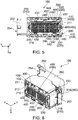
- a connector assembly 10 according to a first embodiment of the present invention comprises a connector 100 and a mating connector 500.
- the mating connector 500 is mateable with and removable from the connector 100 along an up-down direction.
- the up-down direction is a Z-direction. Specifically, upward is a positive Z-direction, and downward is a negative Z-direction.
- the mating connector 500 comprises a mating connector housing 505 and a plurality of male terminals 550.
- the mating connector housing 505 of the present embodiment is integrally molded from resin.
- Each of the male terminals 550 is made of metal.
- the mating connector housing 505 has a surrounding portion 507, a terminal holding portion 508 and a bottom portion accommodating portion 509.
- the surrounding portion 507 is positioned above the terminal holding portion 508 in the up-down direction.
- the surrounding portion 507 surrounds the bottom portion accommodating portion 509 in a plane perpendicular to the up-down direction.
- the plane perpendicular to the up-down direction is an XY-plane.
- the surrounding portion 507 has two short wall portions 512 and two long wall portions 514.
- the two short wall portions 512 face each other in a front-rear direction perpendicular to the up-down direction.
- the front-rear direction is a Y-direction. Specifically, forward is a positive Y-direction, and rearward is a negative Y-direction.
- the two long wall portions 514 face each other in a lateral direction perpendicular to both the up-down direction and the front-rear direction.
- the lateral direction is an X-direction.
- each of the long wall portions 514 is provided with two bosses 510, or two force-receiving portions 510, a first pushing portion 520 and a second pushing portion 530.
- each of the bosses 510 functions as the force-receiving portion 510.
- Each of the bosses 510 protrudes outward in the lateral direction from the outer surface of the long wall portion 514 and has a substantially cylindrical shape.
- the first pushing portion 520 has a substantially trapezoid-like cross-section in a plane perpendicular to the front-rear direction and protrudes outward in the lateral direction from the outer surface of the long wall portion 514.
- the plane perpendicular to the front-rear direction is an XZ-plane.
- the first pushing portion 520 has a slope 522, or a first contact portion 522, which is oblique to both the up-down direction and the lateral direction.
- the slope 522 extends downward and laterally outward from an upper end of the first pushing portion 520.
- the second pushing portion 530 is a plane perpendicular to the up-down direction and has a front end 532 in the front-rear direction.
- the second pushing portion 530 protrudes outward in the lateral direction from the outer surface of the long wall portion 514.
- the first pushing portion 520 and the second pushing portion 530 are arranged in this order in the front-rear direction. Specifically, the first pushing portion 520 is positioned forward of the second pushing portion 530 in the front-rear direction. Accordingly, the connector 100 can have a reduced size in the lateral direction as compared with a connector in which the first pushing portion 520 and the second pushing portion 530 are arranged in the lateral direction.
- the bottom portion accommodating portion 509 has a mating connector opening 516 which is positioned at an upper end thereof in the up-down direction.
- each of the male terminals 550 has a substantially L-like shape as a whole. Specifically, each of the male terminals 550 has a contact point 552 and a fixed portion 554. The contact point 552 is positioned in the vicinity of an upper end of the male terminal 550, and the fixed portion 554 is positioned at an end of the male terminal 550 in a positive X-direction. Each of the male terminals 550 is held by the terminal holding portion 508 of the mating connector housing 505. The fixed portion 554 is configured to be soldered on a circuit board (not shown).
- the connector 100 comprises a housing 200, a lever 300, a slider 400 and a plurality of female terminals 218.
- Each of the housing 200, the lever 300 and the slider 400 is made of resin.
- Each of the female terminals 218 is made of metal.
- the housing 200 comprises a housing main body 210 and a cover portion 250.
- the housing main body 210 is provided with an outer peripheral portion 219, a surrounding portion accommodating portion 211, a bottom portion 212, two housing regulating portions 220, two flat portions 230 and two cavities 240.
- the outer peripheral portion 219 defines an outer edge of the housing main body 210 in the plane perpendicular to the up-down direction.
- the outer peripheral portion 219 surrounds the surrounding portion accommodating portion 211 in the plane perpendicular to the up-down direction.
- the surrounding portion accommodating portion 211 is configured to accommodate the surrounding portion 507 of the mating connector 500.
- the surrounding portion accommodating portion 211 surrounds the bottom portion 212 in the plane perpendicular to the up-down direction.
- the bottom portion 212 is configured to be accommodated by the bottom portion accommodating portion 509 of the mating connector 500.
- the bottom portion 212 is positioned at a lower end of the housing main body 210 in the up-down direction.
- the bottom portion 212 is provided with a plurality of receiving portions 215.
- Each of the receiving portions 215 is a hole which pierces the bottom portion 212 in the up-down direction.
- a set of the housing regulating portion 220, the flat portion 230 and the cavity 240 is provided in the vicinity of each of laterally opposite ends of the housing main body 210.
- the flat portion 230 is a plane perpendicular to the lateral direction and is positioned forward of the housing regulating portion 220 in the front-rear direction.
- the cavity 240 pierces the housing 200 in the lateral direction. Specifically, the cavity 240 communicates with the surrounding portion accommodating portion 211 in the lateral direction and is positioned forward of the flat portion 230 in the front-rear direction.
- the cover portion 250 is positioned above the housing main body 210 in the up-down direction and is attached to the housing main body 210.
- the cover portion 250 is provided with two initial position regulating portions 252 and a cover portion opening 254.
- the initial position regulating portions 252 extend rearward in the front-rear direction from opposite ends, respectively, of the cover portion opening 254 in the lateral direction.
- Each of the initial position regulating portions 252 protrudes outward in the lateral direction.
- the lever 300 is attached to the housing main body 210 of the housing 200 so as to be rotatable between a first position and a second position.
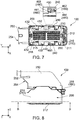
- the first position is a position of the lever 300 shown in each of Figs. 2 and 4
- the second position is a position of the lever 300 shown in each of Figs. 6 and 8 .
- the lever 300 has two pinion portions 310, two arms 314 and a coupling portion 316.
- Each of the pinion portions 310 has pinion teeth 312.
- the pinion portions 310 are connected with lower ends of the arms 314, respectively.
- the coupling portion 316 couples upper ends of the arms 314 with each other.
- each of the initial position regulating portions 252 of the cover portion 250 regulates a forward movement of the lever 300 in the front-rear direction. More specifically, rear ends of the initial position regulating portions 252 are arranged so as to be positioned just forward of front edges of the arms 314, respectively, when the lever 300 is positioned at the first position.
- the slider 400 is attached to the housing main body 210 of the housing 200 so as to be movable in the front-rear direction.
- the slider 400 comprises a pair of side plate portions 410.
- Each of the side plate portions 410 is positioned inward of the outer peripheral portion 219 of the housing main body 210 in the lateral direction.
- Each of the side plate portions 410 is positioned outward of the surrounding portion accommodating portion 211 in the lateral direction.
- the side plate portions 410 correspond to the housing regulating portions 220, the flat portions 230 and the cavities 240, respectively.
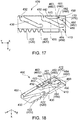
- Each of the side plate portions 410 has a rack portion 420 having rack teeth 422, two cam grooves 430, an arm portion accommodating portion 444, an arm portion fixing portion 442, an arm portion 440, a slider pushed portion 470, a slider regulating portion 480 and a regulated portion 450.
- Each of the side plate portions 410 of the present embodiment is integrally molded from resin. Accordingly, the connector 100 can have a reduced number of parts.
- the pinion portion 310 and the rack portion 420 are meshed with each other to convert a rotational movement of the lever 300 into a movement of the slider 400 in the front-rear direction.
- the side plate portions 410 correspond to the pinion portions 310, respectively, and the rack teeth 422 of the rack portion 420 of each of the side plate portions 410 of the slider 400 and the pinion teeth 312 of the corresponding pinion portion 310 of the lever 300 are meshed with each other to convert a rotational movement of the lever 300 into a movement of the slider 400 in the front-rear direction. Since the lever 300 is attached to the housing main body 210 as described above, the pinion portions 310 of the lever 300 regulate an upward movement of the slider 400.
- the two cam grooves (force-transmitting portions) 430 of the side plate portion 410 are arranged in the front-rear direction.
- Each of the cam grooves (force-transmitting portions) 430 has an opening portion 432 at a lower end thereof in the up-down direction.
- Each of the cam grooves 430 is a ditch which extends rearward and upward from the opening portion 432.
- Each of the cam grooves 430 functions as the force-transmitting portion 430.
- the side plate portions 410 correspond to the long wall portions 514, respectively.
- the cam grooves (force-transmitting portions) 430 of the side plate portion 410 correspond to the bosses (force-receiving portions) 510, respectively, of the corresponding long wall portion 514. Specifically, each of the cam grooves (force-transmitting portions) 430 transmits a force in the up-down direction to the corresponding boss (force-receiving portion) 510 of the mating connector 500 by a movement of the slider 400 in the front-rear direction. More specifically, each of the cam grooves (force-transmitting portions) 430 accommodates the corresponding boss (force-receiving portion) 510 of the mating connector 500 from the opening portion 432 by a forward movement of the slider 400. In addition, each of the cam grooves (force-transmitting portions) 430 moves the corresponding boss (force-receiving portion) 510 of the mating connector 500 toward the opening portion 432 by a rearward movement of the slider 400.
- the arm portion accommodating portion 444 is a recess which is recessed outward in the lateral direction.
- the arm portion 440 extends rearward from a rear end of the arm portion fixing portion 442 and is resiliently deformable.
- the arm portion 440 is positioned inward of an inner surface of the arm portion accommodating portion 444 in the lateral direction.
- the slider pushed portion 470 has a slope 472 oblique to both the up-down direction and the front-rear direction. More specifically, the slope 472 of the slider pushed portion 470 extends rearward and upward from a rear end of the arm portion accommodating portion 444.
- the slider regulating portion 480 has a plane 482 perpendicular to the up-down direction.
- the plane 482 of the slider regulating portion 480 has a front end 484 which is coupled with a rear end of the slope 472 of the slider pushed portion 470 in the front-rear direction.
- the regulated portion 450 is provided on a rear end of the arm portion 440 in the front-rear direction and is movable in the lateral direction.
- the regulated portion 450 has an engaging protrusion 460.
- the engaging protrusion 460 protrudes inward in the lateral direction.
- the engaging protrusion 460 has a lower surface 461, or a second contact portion 461, a rear surface 462, a front surface 463 and a side surface 464.
- the lower surface (second contact portion) 461 is positioned at a lower end of the engaging protrusion 460 in the up-down direction.
- the lower surface (second contact portion) 461 is oblique to both the up-down direction and the lateral direction.
- the rear surface 462 is positioned at a rear end of the engaging protrusion 460 in the front-rear direction.
- the rear surface 462 is oblique to both the front-rear direction and the lateral direction.
- the front surface 463 is a plane which intersects with the front-rear direction.
- the front surface 463 is positioned at a front end of the engaging protrusion 460 in the front-rear direction.
- the front surface 463 of the engaging protrusion 460 and the front-rear direction make an angle equal to or less than 90°.
- the side surface 464 is a plane perpendicular to the lateral direction.
- the side surface 464 is positioned at an inner end of the engaging protrusion 460 in the lateral direction.
- the regulated portion 450, the slider pushed portion 470, and the slider regulating portion 480 are arranged in this order in the front-rear direction. More specifically, the regulated portion 450 is positioned forward of the slider pushed portion 470 in the front-rear direction, and the slider pushed portion 470 is positioned forward of the slider regulating portion 480 in the front-rear direction. Accordingly, the connector 100 can have a reduced size in the lateral direction as compared with a connector in which the regulated portion 450, the slider pushed portion 470 and the slider regulating portion 480 are arranged in the lateral direction.
- the female terminals 218 are connected with the contact points 552 of the male terminals 550, respectively, of the mating connector 500 when the mating connector 500 and the connector 100 are mated with each other.
- the female terminals 218 are held in the receiving portions 215, respectively, of the bottom portion 212 of the housing main body 210.
- a mating operation between the mating connector 500 and the connector 100 is performed as described below.
- each of the housing regulating portions 220 regulates the forward movement of the slider 400 by engagement of the housing regulating portion 220 with the corresponding regulated portion 450.
- a rear surface 222 of each of the housing regulating portions 220 is brought into contact with the front surface 463 of the engaging protrusion 460 of the corresponding regulated portion 450, so that a forward movement of the corresponding regulated portion 450 is regulated. Accordingly, the forward movement of the slider 400 is regulated.
- the slope (first contact portion) 522 of each of the first pushing portions 520 of the mating connector 500 pushes the lower surface (second contact portion) 461 of the engaging protrusion 460 of the corresponding regulated portion 450 to move the engaging protrusion 460 in an intersecting direction which intersects with the front-rear direction.
- the intersecting direction is the lateral direction.
- each of the second pushing portions 530 pushes the slope 472 of the corresponding slider pushed portion 470 to move the slider 400 forward by a predetermined distance. More specifically, when the mating connector 500 is further moved upward relative to the connector 100 to be further manually inserted thereinto, the front end 532 of each of the second pushing portions 530 upwardly pushes the slope 472 of the corresponding slider pushed portion 470 to apply an upward force thereto. Since the upward movement of the slider 400 is regulated by the pinion portions 310 of the lever 300 as described above, the slope 472 of each of the slider pushed portions 470 converts the applied upward force into a forward force.
- each of the second pushing portions 530 pushes the slope 472 of the corresponding slider pushed portion 470 at a point which is gradually moved from a lower end thereof to an upper end thereof, so that the slider 400 is moved forward by the predetermined distance.
- the regulated portion 450 and the corresponding flat portion 230 are arranged in the lateral direction while the arm portion 440 is resiliently deformed.
- each of the lower surface 461, the rear surface 462, the front surface 463 and the side surface 464 of the engaging protrusion 460 of each of the regulated portions 450 is positioned outward of the corresponding flat portion 230 in the lateral direction, and the side surface 464 of the engaging protrusion 460 of each of the regulated portions 450 is brought into contact with the corresponding flat portion 230.
- an upward movement of the mating connector 500 is regulated by each of the second pushing portions 530 abutting against the plane 482 of the corresponding slider regulating portion 480. More specifically, the upward movement of the mating connector 500 is regulated by the front end 532 of each of the second pushing portions 530 abutting against the front end 484 of the plane 482 of the corresponding slider regulating portion 480.
- the slider regulating portion 480 of the present embodiment has the plane 482 perpendicular to the up-down direction, a user can easily recognize that the manual insertion of the mating connector 500 into the connector 100 is completed.
- each of the bosses (force-receiving portions) 510 of the mating connector 500 is positioned in the corresponding cam groove (force-transmitting portion) 430, and the lever 300 is in a state of being rotatable.
- each of the regulated portions 450 is positioned in the corresponding cavity 240 in the front-rear direction while each of the arm portions 440 is not resiliently deformed. More specifically, when the lever 300 is rotated form the first position to the second position after the slider 400 is moved forward by the predetermined distance, the side surface 464 of the engaging protrusion 460 of each of the regulated portions 450 is positioned forward of the corresponding flat portion 230 and inward of the corresponding flat portion 230 in the lateral direction.
- a removal operation of the mating connector 500 and the connector 100 from each other is performed as described below.
- each of the cam grooves (force-transmitting portions) 430 of the slider 400 of the connector 100 moves the corresponding boss (force-receiving portion) 510 of the mating connector 500, which is received in the cam groove (force-transmitting portion) 430 of the slider 400 of the connector 100, in close proximity to the opening portion 432 so that the connector 100 and the mating connector 500 are in the state where the connector 100 and the mating connector 500 are removable from each other.
- each of the regulated portions 450 of the slider 400 rides over the corresponding flat portion 230 of the housing main body 210 to be moved rearward, so that the front surface 463 of the engaging protrusion 460 of each of the regulated portions 450 is engaged with the rear surface 222 of the corresponding housing regulating portion 220.
- each of the regulated portions 450 is prevented from being moved forward, so that the forward movement of the slider 400 is regulated.
- the regulated portion 450 has the lower surface (second contact portion) 461 which is configured to be brought into contact with the slope (first contact portion) 522 of the first pushing portion 520, and the first pushing portion 520 has the slope (first contact portion) 522 which is configured to be brought into contact with the lower surface (second contact portion) 461 of the regulated portion 450.
- each of the lower surface (second contact portion) 461 and the slope (first contact portion) 522 is oblique to both the up-down direction and the lateral direction.
- At least one of the lower surface (second contact portion) 461 of the regulated portion 450 and the slope (first contact portion) 522 of the first pushing portion 520 has a slope which is inclined so that the regulated portion 450 is moved in an intersecting direction when the mating connector 500 is mated with the connector 100, wherein the intersecting direction intersects with the front-rear direction.
- a connector assembly 10A according to a second embodiment of the present invention has a structure same as that of the connector assembly 10 according to the aforementioned first embodiment as shown in Fig. 1 except for a connector 100A.
- Components of the connector 100A shown in Figs. 21 to 24 which are same as those of the connector 100 of the first embodiment are referred by using reference signs same as those of the connector 100 of the first embodiment.
- expressions same as those of the first embodiment will be used hereinbelow.
- the connector 100A has a housing 200A, a lever 300, a slider 400A and a plurality of female terminals 218.
- Each of the housing 200A and the slider 400A is made of resin.
- the lever 300 and the female terminal 218 of the connector 100A have structures same as those of the connector 100 of the aforementioned first embodiment. Accordingly, detailed explanation about those components is omitted.
- the housing 200A comprises a housing main body 210A and a cover portion 250.
- the cover portion 250 has a structure same as that of the connector 100 of the aforementioned first embodiment. Accordingly, detailed explanation about the cover portion 250 is omitted.
- the housing main body 210A is provided with a surrounding portion accommodating portion 211, a bottom portion 212, an outer peripheral portion 219A, two housing regulating portions 220A and two arm portions 228A.
- the surrounding portion accommodating portion 211 and the bottom portion 212 have structures same as those of the connector 100 of the aforementioned first embodiment. Accordingly, detailed explanation about those components is omitted.
- the outer peripheral portion 219A defines an outer edge of the housing main body 210A in a plane perpendicular to the up-down direction.
- the outer peripheral portion 219A surrounds the surrounding portion accommodating portion 211 in the plane perpendicular to the up-down direction.
- Each of the housing regulating portions 220A is a protrusion 224A which protrudes inward from an inner surface of the outer peripheral portion 219A in the lateral direction.
- the protrusions 224A correspond to the arm portions 228A, respectively.
- Each of the protrusions 224A is positioned in the vicinity of a rear end of the corresponding arm portion 228A.
- the protrusion 224A consists of a conical portion 225A and a shank portion 226A.
- the conical portion 225A has a substantially conical shape and extends inward in the lateral direction from a laterally inner end of the shank portion 226A.
- the shank portion 226A has a constant outer dimension in a plane perpendicular to the lateral direction. In the present embodiment, the plane perpendicular to the lateral direction is a YZ-plane.
- the slider 400A is attached to the housing main body 210A of the housing 200A so as to be movable in the front-rear direction.
- the slider 400A comprises a pair of side plate portions 410A.
- the side plate portions 410A correspond to long wall portions 514, respectively.
- Each of the side plate portions 410A is positioned inward of the outer peripheral portion 219A of the housing main body 210A in the lateral direction.
- Each of the side plate portions 410A is positioned outward of the surrounding portion accommodating portion 211 in the lateral direction.
- Each of the side plate portions 410A has a rack portion 420 having rack teeth 422, two cam grooves 430, a slider pushed portion 470, a slider regulating portion 480 and a regulated portion 450A.
- the rack portion 420, the cam groove 430, the slider pushed portion 470 and the slider regulating portion 480 have structures same as those of the connector 100 of the aforementioned first embodiment. Accordingly, detailed explanation about those components is omitted.
- Each of the side plate portions 410A is integrally molded from resin. Accordingly, the connector 100A can have a reduced number of parts.
- the regulated portion 450A is a hole 452A which pierces the side plate portion 410A in the lateral direction.
- the hole 452A consists of a tapered portion 454A and a cylindrical inner peripheral portion 456A.
- the tapered portion 454A has a decreasing inner dimension as measured from a laterally outer end thereof to a laterally inner end thereof.
- the cylindrical inner peripheral portion 456A has a constant inner dimension in the plane perpendicular to the lateral direction and extends inward in the lateral direction from the laterally inner end of the tapered portion 454A.
- the housing regulating portions 220A correspond to the side plate portions 410A, respectively.
- the inner dimension of the cylindrical inner peripheral portion 456A of the hole 452A of the regulated portion 450A of each of the side plate portions 410A is greater than the outer dimension of the shank portion 226A of the protrusion 224A of the corresponding housing regulating portion 220A.
- a mating operation between a mating connector 500 and the connector 100A is performed as described below.
- each of the housing regulating portions 220A regulates a forward movement of the slider 400A by engagement of the housing regulating portion 220A with the corresponding regulated portion 450A.
- each of the housing regulating portions 220A is inserted into the hole 452A of the corresponding regulated portion 450A so that the laterally inner end of the shank portion 226A of the protrusion 224A of each of the housing regulating portions 220A is positioned laterally inward of the laterally inner end of the tapered portion 454A of the hole 452A of the corresponding regulated portion 450A. Accordingly, each of the regulated portions 450A is prevented from being moved forward. Thus, the forward movement of the slider 400A is regulated.
- the laterally inner end of the shank portion 226A of the protrusion 224A of each of the housing regulating portions 220A is positioned laterally outward of the laterally inner end of the tapered portion 454A of the hole 452A of the corresponding regulated portion 450A.
- a laterally outer end of the conical portion 225A of the protrusion 224A of each of the housing regulating portions 220A is positioned laterally outward of a laterally outer end of the cylindrical inner peripheral portion 456A of the hole 452A of the corresponding regulated portion 450A.
- the protrusion 224A of each of the housing regulating portions 220A is in a state where the protrusion 224A of each of the housing regulating portions 220A is able to easily ride over the hole 452A of the corresponding regulated portion 450A when the slider 400A is moved forward.
- the intersecting direction is the lateral direction.
- each of second pushing portions 530 pushes a slope 472 of the corresponding slider pushed portion 470 to move the slider 400A forward by a predetermined distance. More specifically, when the mating connector 500 is further moved upward relative to the connector 100A to be further manually inserted thereinto, a front end 532 of each of the second pushing portions 530 upwardly pushes the slope 472 of the corresponding slider pushed portion 470 to apply an upward force thereto. Since an upward movement of the slider 400A is regulated by pinion portions 310 of the lever 300 similar to the slider 400, the slope 472 of each of the slider pushed portions 470 converts the applied upward force into a forward force.
- each of the second pushing portions 530 pushes the slope 472 of the corresponding slider pushed portion 470 at a point which is gradually moved from a lower end thereof to an upper end thereof, so that the slider 400A is moved forward by the predetermined distance.
- the protrusion 224A of each of the housing regulating portions 220A is positioned outward beyond the hole 452A of the corresponding regulated portion 450A in the lateral direction while each of the arm portions 228A is resiliently deformed.
- an upward movement of the mating connector 500 is regulated by each of the second pushing portions 530 abutting against a plane 482 of the corresponding slider regulating portion 480. More specifically, the upward movement of the mating connector 500 is regulated by the front end 532 of each of the second pushing portions 530 abutting against a front end 484 of the plane 482 of the corresponding slider regulating portion 480. Accordingly, a user can easily recognize that the manual insertion of the mating connector 500 into the connector 100A is completed. Meanwhile, each boss (force-receiving portion) 510 of the mating connector 500 is positioned in the corresponding cam groove (force-transmitting portion) 430, and the lever 300 is in a state of being rotatable.
- the protrusion 224A of each of the housing regulating portions 220A is positioned rearward of a rear end of the slider 400A in the front-rear direction.
- the slider 400A is moved forward in the front-rear direction while each of the cam grooves (force-transmitting portions) 430 moves the corresponding boss (force-receiving portion) 510 of the mating connector 500 upward in the up-down direction so that the connector 100A and the mating connector 500 are mated with each other. Accordingly, a contact point 552 of each of male terminals 550 of the mating connector 500 and the corresponding female terminal 218 of the connector 100A are connected with each other.
- a removal operation of the mating connector 500 and the connector 100A from each other is performed as described below.
- each of the cam grooves (force-transmitting portions) 430 of the slider 400A of the connector 100A moves the corresponding boss (force-receiving portion) 510 of the mating connector 500, which is received in the cam groove (force-transmitting portion) 430 of the slider 400A of the connector 100A, in close proximity to the opening portion 432 so that the connector 100A and the mating connector 500 are in the state where the connector 100A and the mating connector 500 are removable from each other.
- each of the housing regulating portions 220A rides over a laterally outer surface of the slider 400A and is then inserted into the hole 452A of the corresponding regulated portion 450A.
- each of the regulated portions 450A is prevented from being moved forward, so that the forward movement of the slider 400A is regulated.
- the mating connector housing 505 of the mating connector 500 of the present embodiment is integrally molded from resin, the mating connector housing 505 may be formed by combining individual parts.
- the side plate portion 410, 410A of the connector 100, 100A of the present embodiment is integrally molded from resin, the side plate portion 410, 410A may be formed by combining individual parts.
Landscapes
- Details Of Connecting Devices For Male And Female Coupling (AREA)
Applications Claiming Priority (1)
| Application Number | Priority Date | Filing Date | Title |
|---|---|---|---|
| JP2016078148A JP6619285B2 (ja) | 2016-04-08 | 2016-04-08 | コネクタ組立体 |
Publications (2)
| Publication Number | Publication Date |
|---|---|
| EP3229326A1 EP3229326A1 (en) | 2017-10-11 |
| EP3229326B1 true EP3229326B1 (en) | 2018-12-05 |
Family
ID=58094295
Family Applications (1)
| Application Number | Title | Priority Date | Filing Date |
|---|---|---|---|
| EP17156872.8A Not-in-force EP3229326B1 (en) | 2016-04-08 | 2017-02-20 | Connector assembly |
Country Status (2)
| Country | Link |
|---|---|
| EP (1) | EP3229326B1 (https=) |
| JP (1) | JP6619285B2 (https=) |
Cited By (1)
| Publication number | Priority date | Publication date | Assignee | Title |
|---|---|---|---|---|
| EP4718639A1 (en) * | 2024-09-30 | 2026-04-01 | Amphenol East Asia Electronic Technology (Shenzhen) Co., Ltd. | Reliable, versatile, modular electrical connector and module thereof |
Families Citing this family (6)
| Publication number | Priority date | Publication date | Assignee | Title |
|---|---|---|---|---|
| JP7183871B2 (ja) * | 2019-03-05 | 2022-12-06 | 住友電装株式会社 | レバー式コネクタ |
| JP7462523B2 (ja) * | 2020-09-16 | 2024-04-05 | 日本航空電子工業株式会社 | レバー式コネクタ |
| JP7456397B2 (ja) | 2021-02-10 | 2024-03-27 | 住友電装株式会社 | コネクタ |
| JP2023106135A (ja) * | 2022-01-20 | 2023-08-01 | タイコエレクトロニクスジャパン合同会社 | コネクタ |
| JP7850373B2 (ja) * | 2022-06-13 | 2026-04-23 | 株式会社オートネットワーク技術研究所 | コネクタ |
| JP2025132524A (ja) * | 2024-02-29 | 2025-09-10 | TE Connectivity Japan合同会社 | コネクタ |
Family Cites Families (7)
| Publication number | Priority date | Publication date | Assignee | Title |
|---|---|---|---|---|
| FR2730585B1 (fr) * | 1995-02-10 | 1997-04-25 | Framatome Connectors Int | Connecteur electrique a grille de verrouillage de contacts et tiroir |
| US6254407B1 (en) * | 1999-02-17 | 2001-07-03 | Framatome Connectors Interlock, Inc. | Mechanical assist cam slide device |
| ITTO20010290A1 (it) * | 2001-03-27 | 2002-09-27 | Framatome Connectors Italia | Connetore elettrico. |
| US6824406B1 (en) * | 2003-06-26 | 2004-11-30 | Delphi Technologies, Inc. | Electrical connector assembly |
| US20060040535A1 (en) * | 2004-08-20 | 2006-02-23 | Vijy Koshy | Lever type electrical connector with slide members |
| JP5846105B2 (ja) * | 2012-11-13 | 2016-01-20 | 住友電装株式会社 | レバー式コネクタ |
| JP6381904B2 (ja) | 2013-12-24 | 2018-08-29 | タイコエレクトロニクスジャパン合同会社 | レバー式電気コネクタ |
-
2016
- 2016-04-08 JP JP2016078148A patent/JP6619285B2/ja not_active Expired - Fee Related
-
2017
- 2017-02-20 EP EP17156872.8A patent/EP3229326B1/en not_active Not-in-force
Non-Patent Citations (1)
| Title |
|---|
| None * |
Cited By (1)
| Publication number | Priority date | Publication date | Assignee | Title |
|---|---|---|---|---|
| EP4718639A1 (en) * | 2024-09-30 | 2026-04-01 | Amphenol East Asia Electronic Technology (Shenzhen) Co., Ltd. | Reliable, versatile, modular electrical connector and module thereof |
Also Published As
| Publication number | Publication date |
|---|---|
| EP3229326A1 (en) | 2017-10-11 |
| JP2017188390A (ja) | 2017-10-12 |
| JP6619285B2 (ja) | 2019-12-11 |
Similar Documents
| Publication | Publication Date | Title |
|---|---|---|
| EP3229326B1 (en) | Connector assembly | |
| KR101797249B1 (ko) | 커넥터 단자 위치 보장 장치 | |
| US7255581B2 (en) | Lever-type connector | |
| EP1830436B1 (en) | A connector, connector assembly and assembling method | |
| US7828583B2 (en) | Connector with an aligner with a flexible deformable arm with a slit | |
| EP1571734B1 (en) | Connector apparatus with a mating detecting member called connector position assurance | |
| JP2013187116A (ja) | コネクタ | |
| JP4683577B2 (ja) | ロック解除装置及びコネクタ装置 | |
| US7445475B2 (en) | Lever type connector | |
| JP2004063115A (ja) | コネクタ | |
| US9905965B2 (en) | Connector and connector assembly | |
| KR20160118145A (ko) | 전기 커넥터 | |
| US20170093088A1 (en) | Connector and connector assembly | |
| JP2011142050A (ja) | レバー式コネクタ | |
| CN112005446A (zh) | 连接器位置保证构件 | |
| KR20170070997A (ko) | 커넥터의 록킹 구조 및 커넥터 | |
| CN201699214U (zh) | 电连接器的锁定装置 | |
| JP4950797B2 (ja) | 可動ガイド部材付きコネクタ | |
| JP2004139758A (ja) | コネクタ | |
| JP2016091819A (ja) | コネクタ | |
| JP2002313488A (ja) | 分割コネクタ | |
| JP2003272750A (ja) | コネクタ | |
| CN110249488A (zh) | 连接器 | |
| US11133622B2 (en) | Connector with connection detection member | |
| EP4439877A1 (en) | Structure, release jig and unlocking method of lock of structure using release jig |
Legal Events
| Date | Code | Title | Description |
|---|---|---|---|
| PUAI | Public reference made under article 153(3) epc to a published international application that has entered the european phase |
Free format text: ORIGINAL CODE: 0009012 |
|
| STAA | Information on the status of an ep patent application or granted ep patent |
Free format text: STATUS: THE APPLICATION HAS BEEN PUBLISHED |
|
| AK | Designated contracting states |
Kind code of ref document: A1 Designated state(s): AL AT BE BG CH CY CZ DE DK EE ES FI FR GB GR HR HU IE IS IT LI LT LU LV MC MK MT NL NO PL PT RO RS SE SI SK SM TR |
|
| AX | Request for extension of the european patent |
Extension state: BA ME |
|
| STAA | Information on the status of an ep patent application or granted ep patent |
Free format text: STATUS: REQUEST FOR EXAMINATION WAS MADE |
|
| 17P | Request for examination filed |
Effective date: 20180226 |
|
| RBV | Designated contracting states (corrected) |
Designated state(s): AL AT BE BG CH CY CZ DE DK EE ES FI FR GB GR HR HU IE IS IT LI LT LU LV MC MK MT NL NO PL PT RO RS SE SI SK SM TR |
|
| GRAP | Despatch of communication of intention to grant a patent |
Free format text: ORIGINAL CODE: EPIDOSNIGR1 |
|
| STAA | Information on the status of an ep patent application or granted ep patent |
Free format text: STATUS: GRANT OF PATENT IS INTENDED |
|
| RIC1 | Information provided on ipc code assigned before grant |
Ipc: H01R 13/629 20060101AFI20180529BHEP Ipc: H01R 13/645 20060101ALN20180529BHEP |
|
| RIC1 | Information provided on ipc code assigned before grant |
Ipc: H01R 13/645 20060101ALN20180605BHEP Ipc: H01R 13/629 20060101AFI20180605BHEP |
|
| INTG | Intention to grant announced |
Effective date: 20180620 |
|
| GRAS | Grant fee paid |
Free format text: ORIGINAL CODE: EPIDOSNIGR3 |
|
| GRAA | (expected) grant |
Free format text: ORIGINAL CODE: 0009210 |
|
| STAA | Information on the status of an ep patent application or granted ep patent |
Free format text: STATUS: THE PATENT HAS BEEN GRANTED |
|
| AK | Designated contracting states |
Kind code of ref document: B1 Designated state(s): AL AT BE BG CH CY CZ DE DK EE ES FI FR GB GR HR HU IE IS IT LI LT LU LV MC MK MT NL NO PL PT RO RS SE SI SK SM TR |
|
| REG | Reference to a national code |
Ref country code: GB Ref legal event code: FG4D |
|
| REG | Reference to a national code |
Ref country code: CH Ref legal event code: EP |
|
| REG | Reference to a national code |
Ref country code: AT Ref legal event code: REF Ref document number: 1074232 Country of ref document: AT Kind code of ref document: T Effective date: 20181215 |
|
| REG | Reference to a national code |
Ref country code: IE Ref legal event code: FG4D |
|
| REG | Reference to a national code |
Ref country code: DE Ref legal event code: R096 Ref document number: 602017001122 Country of ref document: DE |
|
| REG | Reference to a national code |
Ref country code: NL Ref legal event code: MP Effective date: 20181205 |
|
| REG | Reference to a national code |
Ref country code: AT Ref legal event code: MK05 Ref document number: 1074232 Country of ref document: AT Kind code of ref document: T Effective date: 20181205 |
|
| REG | Reference to a national code |
Ref country code: LT Ref legal event code: MG4D |
|
| PG25 | Lapsed in a contracting state [announced via postgrant information from national office to epo] |
Ref country code: ES Free format text: LAPSE BECAUSE OF FAILURE TO SUBMIT A TRANSLATION OF THE DESCRIPTION OR TO PAY THE FEE WITHIN THE PRESCRIBED TIME-LIMIT Effective date: 20181205 Ref country code: AT Free format text: LAPSE BECAUSE OF FAILURE TO SUBMIT A TRANSLATION OF THE DESCRIPTION OR TO PAY THE FEE WITHIN THE PRESCRIBED TIME-LIMIT Effective date: 20181205 Ref country code: LT Free format text: LAPSE BECAUSE OF FAILURE TO SUBMIT A TRANSLATION OF THE DESCRIPTION OR TO PAY THE FEE WITHIN THE PRESCRIBED TIME-LIMIT Effective date: 20181205 Ref country code: NO Free format text: LAPSE BECAUSE OF FAILURE TO SUBMIT A TRANSLATION OF THE DESCRIPTION OR TO PAY THE FEE WITHIN THE PRESCRIBED TIME-LIMIT Effective date: 20190305 Ref country code: FI Free format text: LAPSE BECAUSE OF FAILURE TO SUBMIT A TRANSLATION OF THE DESCRIPTION OR TO PAY THE FEE WITHIN THE PRESCRIBED TIME-LIMIT Effective date: 20181205 Ref country code: BG Free format text: LAPSE BECAUSE OF FAILURE TO SUBMIT A TRANSLATION OF THE DESCRIPTION OR TO PAY THE FEE WITHIN THE PRESCRIBED TIME-LIMIT Effective date: 20190305 Ref country code: HR Free format text: LAPSE BECAUSE OF FAILURE TO SUBMIT A TRANSLATION OF THE DESCRIPTION OR TO PAY THE FEE WITHIN THE PRESCRIBED TIME-LIMIT Effective date: 20181205 Ref country code: LV Free format text: LAPSE BECAUSE OF FAILURE TO SUBMIT A TRANSLATION OF THE DESCRIPTION OR TO PAY THE FEE WITHIN THE PRESCRIBED TIME-LIMIT Effective date: 20181205 |
|
| PG25 | Lapsed in a contracting state [announced via postgrant information from national office to epo] |
Ref country code: RS Free format text: LAPSE BECAUSE OF FAILURE TO SUBMIT A TRANSLATION OF THE DESCRIPTION OR TO PAY THE FEE WITHIN THE PRESCRIBED TIME-LIMIT Effective date: 20181205 Ref country code: GR Free format text: LAPSE BECAUSE OF FAILURE TO SUBMIT A TRANSLATION OF THE DESCRIPTION OR TO PAY THE FEE WITHIN THE PRESCRIBED TIME-LIMIT Effective date: 20190306 Ref country code: AL Free format text: LAPSE BECAUSE OF FAILURE TO SUBMIT A TRANSLATION OF THE DESCRIPTION OR TO PAY THE FEE WITHIN THE PRESCRIBED TIME-LIMIT Effective date: 20181205 Ref country code: SE Free format text: LAPSE BECAUSE OF FAILURE TO SUBMIT A TRANSLATION OF THE DESCRIPTION OR TO PAY THE FEE WITHIN THE PRESCRIBED TIME-LIMIT Effective date: 20181205 |
|
| PG25 | Lapsed in a contracting state [announced via postgrant information from national office to epo] |
Ref country code: NL Free format text: LAPSE BECAUSE OF FAILURE TO SUBMIT A TRANSLATION OF THE DESCRIPTION OR TO PAY THE FEE WITHIN THE PRESCRIBED TIME-LIMIT Effective date: 20181205 |
|
| PG25 | Lapsed in a contracting state [announced via postgrant information from national office to epo] |
Ref country code: PL Free format text: LAPSE BECAUSE OF FAILURE TO SUBMIT A TRANSLATION OF THE DESCRIPTION OR TO PAY THE FEE WITHIN THE PRESCRIBED TIME-LIMIT Effective date: 20181205 Ref country code: IT Free format text: LAPSE BECAUSE OF FAILURE TO SUBMIT A TRANSLATION OF THE DESCRIPTION OR TO PAY THE FEE WITHIN THE PRESCRIBED TIME-LIMIT Effective date: 20181205 Ref country code: PT Free format text: LAPSE BECAUSE OF FAILURE TO SUBMIT A TRANSLATION OF THE DESCRIPTION OR TO PAY THE FEE WITHIN THE PRESCRIBED TIME-LIMIT Effective date: 20190405 Ref country code: CZ Free format text: LAPSE BECAUSE OF FAILURE TO SUBMIT A TRANSLATION OF THE DESCRIPTION OR TO PAY THE FEE WITHIN THE PRESCRIBED TIME-LIMIT Effective date: 20181205 |
|
| PG25 | Lapsed in a contracting state [announced via postgrant information from national office to epo] |
Ref country code: RO Free format text: LAPSE BECAUSE OF FAILURE TO SUBMIT A TRANSLATION OF THE DESCRIPTION OR TO PAY THE FEE WITHIN THE PRESCRIBED TIME-LIMIT Effective date: 20181205 Ref country code: IS Free format text: LAPSE BECAUSE OF FAILURE TO SUBMIT A TRANSLATION OF THE DESCRIPTION OR TO PAY THE FEE WITHIN THE PRESCRIBED TIME-LIMIT Effective date: 20190405 Ref country code: SM Free format text: LAPSE BECAUSE OF FAILURE TO SUBMIT A TRANSLATION OF THE DESCRIPTION OR TO PAY THE FEE WITHIN THE PRESCRIBED TIME-LIMIT Effective date: 20181205 Ref country code: EE Free format text: LAPSE BECAUSE OF FAILURE TO SUBMIT A TRANSLATION OF THE DESCRIPTION OR TO PAY THE FEE WITHIN THE PRESCRIBED TIME-LIMIT Effective date: 20181205 Ref country code: SK Free format text: LAPSE BECAUSE OF FAILURE TO SUBMIT A TRANSLATION OF THE DESCRIPTION OR TO PAY THE FEE WITHIN THE PRESCRIBED TIME-LIMIT Effective date: 20181205 |
|
| REG | Reference to a national code |
Ref country code: DE Ref legal event code: R097 Ref document number: 602017001122 Country of ref document: DE |
|
| PLBE | No opposition filed within time limit |
Free format text: ORIGINAL CODE: 0009261 |
|
| STAA | Information on the status of an ep patent application or granted ep patent |
Free format text: STATUS: NO OPPOSITION FILED WITHIN TIME LIMIT |
|
| PG25 | Lapsed in a contracting state [announced via postgrant information from national office to epo] |
Ref country code: SI Free format text: LAPSE BECAUSE OF FAILURE TO SUBMIT A TRANSLATION OF THE DESCRIPTION OR TO PAY THE FEE WITHIN THE PRESCRIBED TIME-LIMIT Effective date: 20181205 Ref country code: DK Free format text: LAPSE BECAUSE OF FAILURE TO SUBMIT A TRANSLATION OF THE DESCRIPTION OR TO PAY THE FEE WITHIN THE PRESCRIBED TIME-LIMIT Effective date: 20181205 Ref country code: LU Free format text: LAPSE BECAUSE OF NON-PAYMENT OF DUE FEES Effective date: 20190220 Ref country code: MC Free format text: LAPSE BECAUSE OF FAILURE TO SUBMIT A TRANSLATION OF THE DESCRIPTION OR TO PAY THE FEE WITHIN THE PRESCRIBED TIME-LIMIT Effective date: 20181205 |
|
| 26N | No opposition filed |
Effective date: 20190906 |
|
| REG | Reference to a national code |
Ref country code: BE Ref legal event code: MM Effective date: 20190228 |
|
| REG | Reference to a national code |
Ref country code: IE Ref legal event code: MM4A |
|
| PG25 | Lapsed in a contracting state [announced via postgrant information from national office to epo] |
Ref country code: IE Free format text: LAPSE BECAUSE OF NON-PAYMENT OF DUE FEES Effective date: 20190220 |
|
| PG25 | Lapsed in a contracting state [announced via postgrant information from national office to epo] |
Ref country code: BE Free format text: LAPSE BECAUSE OF NON-PAYMENT OF DUE FEES Effective date: 20190228 |
|
| PG25 | Lapsed in a contracting state [announced via postgrant information from national office to epo] |
Ref country code: TR Free format text: LAPSE BECAUSE OF FAILURE TO SUBMIT A TRANSLATION OF THE DESCRIPTION OR TO PAY THE FEE WITHIN THE PRESCRIBED TIME-LIMIT Effective date: 20181205 |
|
| PG25 | Lapsed in a contracting state [announced via postgrant information from national office to epo] |
Ref country code: MT Free format text: LAPSE BECAUSE OF NON-PAYMENT OF DUE FEES Effective date: 20190220 |
|
| REG | Reference to a national code |
Ref country code: CH Ref legal event code: PL |
|
| PG25 | Lapsed in a contracting state [announced via postgrant information from national office to epo] |
Ref country code: CH Free format text: LAPSE BECAUSE OF NON-PAYMENT OF DUE FEES Effective date: 20200229 Ref country code: LI Free format text: LAPSE BECAUSE OF NON-PAYMENT OF DUE FEES Effective date: 20200229 |
|
| PG25 | Lapsed in a contracting state [announced via postgrant information from national office to epo] |
Ref country code: CY Free format text: LAPSE BECAUSE OF FAILURE TO SUBMIT A TRANSLATION OF THE DESCRIPTION OR TO PAY THE FEE WITHIN THE PRESCRIBED TIME-LIMIT Effective date: 20181205 |
|
| PG25 | Lapsed in a contracting state [announced via postgrant information from national office to epo] |
Ref country code: HU Free format text: LAPSE BECAUSE OF FAILURE TO SUBMIT A TRANSLATION OF THE DESCRIPTION OR TO PAY THE FEE WITHIN THE PRESCRIBED TIME-LIMIT; INVALID AB INITIO Effective date: 20170220 |
|
| GBPC | Gb: european patent ceased through non-payment of renewal fee |
Effective date: 20210220 |
|
| PG25 | Lapsed in a contracting state [announced via postgrant information from national office to epo] |
Ref country code: GB Free format text: LAPSE BECAUSE OF NON-PAYMENT OF DUE FEES Effective date: 20210220 |
|
| PG25 | Lapsed in a contracting state [announced via postgrant information from national office to epo] |
Ref country code: MK Free format text: LAPSE BECAUSE OF FAILURE TO SUBMIT A TRANSLATION OF THE DESCRIPTION OR TO PAY THE FEE WITHIN THE PRESCRIBED TIME-LIMIT Effective date: 20181205 |
|
| PGFP | Annual fee paid to national office [announced via postgrant information from national office to epo] |
Ref country code: FR Payment date: 20230110 Year of fee payment: 7 |
|
| PGFP | Annual fee paid to national office [announced via postgrant information from national office to epo] |
Ref country code: DE Payment date: 20221229 Year of fee payment: 7 |
|
| REG | Reference to a national code |
Ref country code: DE Ref legal event code: R119 Ref document number: 602017001122 Country of ref document: DE |
|
| PG25 | Lapsed in a contracting state [announced via postgrant information from national office to epo] |
Ref country code: DE Free format text: LAPSE BECAUSE OF NON-PAYMENT OF DUE FEES Effective date: 20240903 |
|
| PG25 | Lapsed in a contracting state [announced via postgrant information from national office to epo] |
Ref country code: FR Free format text: LAPSE BECAUSE OF NON-PAYMENT OF DUE FEES Effective date: 20240229 |
|
| PG25 | Lapsed in a contracting state [announced via postgrant information from national office to epo] |
Ref country code: FR Free format text: LAPSE BECAUSE OF NON-PAYMENT OF DUE FEES Effective date: 20240229 Ref country code: DE Free format text: LAPSE BECAUSE OF NON-PAYMENT OF DUE FEES Effective date: 20240903 |