EP3228986B1 - Vermessungssystem - Google Patents
Vermessungssystem Download PDFInfo
- Publication number
- EP3228986B1 EP3228986B1 EP16202710.6A EP16202710A EP3228986B1 EP 3228986 B1 EP3228986 B1 EP 3228986B1 EP 16202710 A EP16202710 A EP 16202710A EP 3228986 B1 EP3228986 B1 EP 3228986B1
- Authority
- EP
- European Patent Office
- Prior art keywords
- images
- image
- camera
- surveying
- surveying system
- Prior art date
- Legal status (The legal status is an assumption and is not a legal conclusion. Google has not performed a legal analysis and makes no representation as to the accuracy of the status listed.)
- Active
Links
- 238000005259 measurement Methods 0.000 claims description 59
- 238000004422 calculation algorithm Methods 0.000 claims description 37
- 238000011156 evaluation Methods 0.000 claims description 30
- 238000002271 resection Methods 0.000 claims description 16
- 238000012545 processing Methods 0.000 description 45
- 230000033001 locomotion Effects 0.000 description 34
- 238000000034 method Methods 0.000 description 16
- 230000003287 optical effect Effects 0.000 description 7
- 230000001960 triggered effect Effects 0.000 description 7
- 239000013598 vector Substances 0.000 description 7
- 238000001514 detection method Methods 0.000 description 6
- 230000002452 interceptive effect Effects 0.000 description 6
- 238000012800 visualization Methods 0.000 description 6
- 239000006096 absorbing agent Substances 0.000 description 5
- 230000008859 change Effects 0.000 description 5
- 230000001360 synchronised effect Effects 0.000 description 5
- 230000001133 acceleration Effects 0.000 description 4
- 238000013459 approach Methods 0.000 description 4
- 230000008901 benefit Effects 0.000 description 4
- 238000009795 derivation Methods 0.000 description 4
- 238000003384 imaging method Methods 0.000 description 4
- 230000008569 process Effects 0.000 description 4
- 239000011521 glass Substances 0.000 description 3
- 230000004807 localization Effects 0.000 description 3
- 230000009467 reduction Effects 0.000 description 3
- 230000003068 static effect Effects 0.000 description 3
- 238000004458 analytical method Methods 0.000 description 2
- 230000005540 biological transmission Effects 0.000 description 2
- 238000013144 data compression Methods 0.000 description 2
- 238000013461 design Methods 0.000 description 2
- 230000004927 fusion Effects 0.000 description 2
- 230000005484 gravity Effects 0.000 description 2
- 230000003993 interaction Effects 0.000 description 2
- 230000000873 masking effect Effects 0.000 description 2
- 238000012986 modification Methods 0.000 description 2
- 230000004048 modification Effects 0.000 description 2
- 230000002829 reductive effect Effects 0.000 description 2
- 230000011218 segmentation Effects 0.000 description 2
- 238000003786 synthesis reaction Methods 0.000 description 2
- 238000012546 transfer Methods 0.000 description 2
- 238000012935 Averaging Methods 0.000 description 1
- 238000009825 accumulation Methods 0.000 description 1
- 230000003044 adaptive effect Effects 0.000 description 1
- 230000003190 augmentative effect Effects 0.000 description 1
- 230000015572 biosynthetic process Effects 0.000 description 1
- 238000004364 calculation method Methods 0.000 description 1
- 239000003086 colorant Substances 0.000 description 1
- 238000004040 coloring Methods 0.000 description 1
- 230000000295 complement effect Effects 0.000 description 1
- 239000002131 composite material Substances 0.000 description 1
- 238000007906 compression Methods 0.000 description 1
- 230000006835 compression Effects 0.000 description 1
- 238000010276 construction Methods 0.000 description 1
- 238000013016 damping Methods 0.000 description 1
- 238000013481 data capture Methods 0.000 description 1
- 230000000694 effects Effects 0.000 description 1
- 230000008030 elimination Effects 0.000 description 1
- 238000003379 elimination reaction Methods 0.000 description 1
- 230000007717 exclusion Effects 0.000 description 1
- 238000000605 extraction Methods 0.000 description 1
- 230000010354 integration Effects 0.000 description 1
- 230000001788 irregular Effects 0.000 description 1
- 238000013507 mapping Methods 0.000 description 1
- 239000011159 matrix material Substances 0.000 description 1
- 230000007246 mechanism Effects 0.000 description 1
- 239000003973 paint Substances 0.000 description 1
- 230000036961 partial effect Effects 0.000 description 1
- 239000002245 particle Substances 0.000 description 1
- 230000010287 polarization Effects 0.000 description 1
- 238000007781 pre-processing Methods 0.000 description 1
- 238000001556 precipitation Methods 0.000 description 1
- 238000001454 recorded image Methods 0.000 description 1
- 230000035939 shock Effects 0.000 description 1
- 230000005236 sound signal Effects 0.000 description 1
- 230000006641 stabilisation Effects 0.000 description 1
- 238000011105 stabilization Methods 0.000 description 1
- 230000037072 sun protection Effects 0.000 description 1
- 238000004441 surface measurement Methods 0.000 description 1
- 238000010408 sweeping Methods 0.000 description 1
- 230000009466 transformation Effects 0.000 description 1
Images


Classifications
-
- G—PHYSICS
- G01—MEASURING; TESTING
- G01C—MEASURING DISTANCES, LEVELS OR BEARINGS; SURVEYING; NAVIGATION; GYROSCOPIC INSTRUMENTS; PHOTOGRAMMETRY OR VIDEOGRAMMETRY
- G01C15/00—Surveying instruments or accessories not provided for in groups G01C1/00 - G01C13/00
- G01C15/002—Active optical surveying means
- G01C15/004—Reference lines, planes or sectors
- G01C15/006—Detectors therefor
-
- G—PHYSICS
- G01—MEASURING; TESTING
- G01C—MEASURING DISTANCES, LEVELS OR BEARINGS; SURVEYING; NAVIGATION; GYROSCOPIC INSTRUMENTS; PHOTOGRAMMETRY OR VIDEOGRAMMETRY
- G01C11/00—Photogrammetry or videogrammetry, e.g. stereogrammetry; Photographic surveying
- G01C11/04—Interpretation of pictures
-
- G—PHYSICS
- G01—MEASURING; TESTING
- G01C—MEASURING DISTANCES, LEVELS OR BEARINGS; SURVEYING; NAVIGATION; GYROSCOPIC INSTRUMENTS; PHOTOGRAMMETRY OR VIDEOGRAMMETRY
- G01C11/00—Photogrammetry or videogrammetry, e.g. stereogrammetry; Photographic surveying
- G01C11/02—Picture taking arrangements specially adapted for photogrammetry or photographic surveying, e.g. controlling overlapping of pictures
-
- G—PHYSICS
- G01—MEASURING; TESTING
- G01C—MEASURING DISTANCES, LEVELS OR BEARINGS; SURVEYING; NAVIGATION; GYROSCOPIC INSTRUMENTS; PHOTOGRAMMETRY OR VIDEOGRAMMETRY
- G01C25/00—Manufacturing, calibrating, cleaning, or repairing instruments or devices referred to in the other groups of this subclass
- G01C25/005—Manufacturing, calibrating, cleaning, or repairing instruments or devices referred to in the other groups of this subclass initial alignment, calibration or starting-up of inertial devices
-
- G—PHYSICS
- G01—MEASURING; TESTING
- G01S—RADIO DIRECTION-FINDING; RADIO NAVIGATION; DETERMINING DISTANCE OR VELOCITY BY USE OF RADIO WAVES; LOCATING OR PRESENCE-DETECTING BY USE OF THE REFLECTION OR RERADIATION OF RADIO WAVES; ANALOGOUS ARRANGEMENTS USING OTHER WAVES
- G01S19/00—Satellite radio beacon positioning systems; Determining position, velocity or attitude using signals transmitted by such systems
- G01S19/01—Satellite radio beacon positioning systems transmitting time-stamped messages, e.g. GPS [Global Positioning System], GLONASS [Global Orbiting Navigation Satellite System] or GALILEO
- G01S19/03—Cooperating elements; Interaction or communication between different cooperating elements or between cooperating elements and receivers
- G01S19/10—Cooperating elements; Interaction or communication between different cooperating elements or between cooperating elements and receivers providing dedicated supplementary positioning signals
-
- G—PHYSICS
- G01—MEASURING; TESTING
- G01S—RADIO DIRECTION-FINDING; RADIO NAVIGATION; DETERMINING DISTANCE OR VELOCITY BY USE OF RADIO WAVES; LOCATING OR PRESENCE-DETECTING BY USE OF THE REFLECTION OR RERADIATION OF RADIO WAVES; ANALOGOUS ARRANGEMENTS USING OTHER WAVES
- G01S19/00—Satellite radio beacon positioning systems; Determining position, velocity or attitude using signals transmitted by such systems
- G01S19/01—Satellite radio beacon positioning systems transmitting time-stamped messages, e.g. GPS [Global Positioning System], GLONASS [Global Orbiting Navigation Satellite System] or GALILEO
- G01S19/13—Receivers
- G01S19/14—Receivers specially adapted for specific applications
-
- G—PHYSICS
- G06—COMPUTING; CALCULATING OR COUNTING
- G06T—IMAGE DATA PROCESSING OR GENERATION, IN GENERAL
- G06T7/00—Image analysis
- G06T7/0002—Inspection of images, e.g. flaw detection
-
- G—PHYSICS
- G06—COMPUTING; CALCULATING OR COUNTING
- G06T—IMAGE DATA PROCESSING OR GENERATION, IN GENERAL
- G06T7/00—Image analysis
- G06T7/0002—Inspection of images, e.g. flaw detection
- G06T7/0004—Industrial image inspection
-
- G—PHYSICS
- G06—COMPUTING; CALCULATING OR COUNTING
- G06T—IMAGE DATA PROCESSING OR GENERATION, IN GENERAL
- G06T7/00—Image analysis
- G06T7/50—Depth or shape recovery
- G06T7/55—Depth or shape recovery from multiple images
- G06T7/579—Depth or shape recovery from multiple images from motion
-
- G—PHYSICS
- G06—COMPUTING; CALCULATING OR COUNTING
- G06T—IMAGE DATA PROCESSING OR GENERATION, IN GENERAL
- G06T7/00—Image analysis
- G06T7/70—Determining position or orientation of objects or cameras
-
- G—PHYSICS
- G06—COMPUTING; CALCULATING OR COUNTING
- G06T—IMAGE DATA PROCESSING OR GENERATION, IN GENERAL
- G06T7/00—Image analysis
- G06T7/97—Determining parameters from multiple pictures
-
- H—ELECTRICITY
- H04—ELECTRIC COMMUNICATION TECHNIQUE
- H04N—PICTORIAL COMMUNICATION, e.g. TELEVISION
- H04N23/00—Cameras or camera modules comprising electronic image sensors; Control thereof
- H04N23/50—Constructional details
- H04N23/51—Housings
-
- H—ELECTRICITY
- H04—ELECTRIC COMMUNICATION TECHNIQUE
- H04N—PICTORIAL COMMUNICATION, e.g. TELEVISION
- H04N23/00—Cameras or camera modules comprising electronic image sensors; Control thereof
- H04N23/50—Constructional details
- H04N23/55—Optical parts specially adapted for electronic image sensors; Mounting thereof
-
- H—ELECTRICITY
- H04—ELECTRIC COMMUNICATION TECHNIQUE
- H04N—PICTORIAL COMMUNICATION, e.g. TELEVISION
- H04N23/00—Cameras or camera modules comprising electronic image sensors; Control thereof
- H04N23/57—Mechanical or electrical details of cameras or camera modules specially adapted for being embedded in other devices
-
- H—ELECTRICITY
- H04—ELECTRIC COMMUNICATION TECHNIQUE
- H04N—PICTORIAL COMMUNICATION, e.g. TELEVISION
- H04N23/00—Cameras or camera modules comprising electronic image sensors; Control thereof
- H04N23/60—Control of cameras or camera modules
- H04N23/63—Control of cameras or camera modules by using electronic viewfinders
- H04N23/633—Control of cameras or camera modules by using electronic viewfinders for displaying additional information relating to control or operation of the camera
- H04N23/635—Region indicators; Field of view indicators
-
- H—ELECTRICITY
- H04—ELECTRIC COMMUNICATION TECHNIQUE
- H04N—PICTORIAL COMMUNICATION, e.g. TELEVISION
- H04N23/00—Cameras or camera modules comprising electronic image sensors; Control thereof
- H04N23/60—Control of cameras or camera modules
- H04N23/69—Control of means for changing angle of the field of view, e.g. optical zoom objectives or electronic zooming
-
- H—ELECTRICITY
- H04—ELECTRIC COMMUNICATION TECHNIQUE
- H04N—PICTORIAL COMMUNICATION, e.g. TELEVISION
- H04N23/00—Cameras or camera modules comprising electronic image sensors; Control thereof
- H04N23/60—Control of cameras or camera modules
- H04N23/698—Control of cameras or camera modules for achieving an enlarged field of view, e.g. panoramic image capture
-
- H—ELECTRICITY
- H04—ELECTRIC COMMUNICATION TECHNIQUE
- H04N—PICTORIAL COMMUNICATION, e.g. TELEVISION
- H04N23/00—Cameras or camera modules comprising electronic image sensors; Control thereof
- H04N23/90—Arrangement of cameras or camera modules, e.g. multiple cameras in TV studios or sports stadiums
-
- G—PHYSICS
- G06—COMPUTING; CALCULATING OR COUNTING
- G06T—IMAGE DATA PROCESSING OR GENERATION, IN GENERAL
- G06T2207/00—Indexing scheme for image analysis or image enhancement
- G06T2207/10—Image acquisition modality
- G06T2207/10028—Range image; Depth image; 3D point clouds
-
- G—PHYSICS
- G06—COMPUTING; CALCULATING OR COUNTING
- G06T—IMAGE DATA PROCESSING OR GENERATION, IN GENERAL
- G06T2207/00—Indexing scheme for image analysis or image enhancement
- G06T2207/30—Subject of image; Context of image processing
- G06T2207/30244—Camera pose
Definitions
- the present invention pertains to a surveying system comprising a camera module providing images for performing a SLAM- or SfM-algorithm.
- the invention describes a camera module which can be attached on a pole to a GNSS-antenna or a reflector for the measurement of points without the levelling step.
- the camera module enables the measurement of points where the GNSS-signal or the line-of-sight between total station and pole is interrupted.
- a point cloud of the environment can be derived.
- rectified views or orthophotos can be generated, e. g. of the terrain or a façade.
- the surveyor places the pole tip onto the measuring point, levels the pole and triggers the measurement.
- the levelling step takes some time and - if not carried out properly - leads to a degraded measurement result.
- Surveying with a GNSS-pole is only possible at places, where the signals of a sufficient number of GNSS satellites can be received. When the surveyor moves close to a building, some of the satellite signals may be not receivable anymore. Thus, at such a place a measurement is not possible at all.
- a GNSS surveying system can record absolute positions with good accuracy on a global scale, e. g. 2-4 cm. However, such a system can record only single points, where the operator must position the GNSS pole vertically on top of point to be measured. The derivation of a point cloud with a GNSS-pole is not state-of-the-art.
- US 2011/0064312 A1 relates to image-based geo-referencing and discloses a combination of GNSS measurements with image processing to provide new solutions for positioning.
- Stored geo-referenced images are compared (feature-correlated) with actual images made by a GNSS receiver. This is then used to qualify the accuracy of the GNSS measurement or complement missing parts (e.g. height information). It is also possible the other way round, i.e. the GNSS measurement is used to update the geo-reference of the stored images. This can also be used to determine a local coordinate system.
- US 2011/0157359 A1 discloses aligning a virtual perspective centre of a camera with the measurement (antenna) centre of a position measurement system. This facilitates computations in a combined image/GNSS system.
- WO 2011/163454 A1 discloses a method and apparatus for image-based positioning, tracking image features from one image to the next in order to determine the position change of a GNSS receiver using SLAM techniques.
- WO 2010/080950 A1 discloses determining orientation of a GNSS receiver from image data.
- a processing of data recorded by a system with cameras requires high computational resources.
- the state-of-the-art solution is known as processing of data on a powerful laptop, PC or on an external cloud server.
- the processing time might be quite time consuming and usually is performed in the office.
- One or more external portable computational devices e.g. smartphone, tablet PC, laptop
- the system has a cable or wireless connection with at least one of these computational devices.
- the data are transferred to these devices and all computations are automatically distributed between all available computational devices. All computational devices could communicate between each other.
- one advantage of such solution is an ability to use all available computational resources for fast in-field data processing or visualization. New devices could be easily added for computation without updating of the surveying device.
- the invention relates to a surveying system according to claim 1, comprising a surveying pole, a display means, a position measuring resource being mounted on the surveying pole, wherein positions of the position measuring resource are determinable by the surveying system, and a surveying subsystem, the surveying subsystem comprising a camera module and a control and evaluation unit.
- the camera module is designed to be attached to the surveying pole and comprises at least one camera for capturing images.
- the control and evaluation unit has stored a program with program code so as to control and execute a remote point measurement functionality in which
- the control and evaluation unit is configured so that the remote point measurement functionality is controlled and executed in such a way that an image point in an image of the surrounding is manually selectable by a user on a display means, said image basing on at least one of the images of the series of images, wherein, upon selection of the image point, a 3D position of the remote point being represented by said selected image point is derived, wherein a subset of images in which the remote point appears is automatically identified from the series of images and the 3D position is determined based on forward intersection using said subset of images and the determined camera poses for the images of said subset.
- control and evaluation unit is configured so that the remote point measurement functionality is controlled and executed in such a way that the subset comprises all images in which the remote point appears.
- the position measuring resource comprises a GNSS-antenna or a retro-reflector.
- control and evaluation unit is configured so that the remote point measurement functionality is controlled and executed in such a way that
- positions and external orientations of the at least one camera are derived in the coordinate system of the surveying system in six degrees of freedom.
- the multitude of determined positions of the position measuring resource comprise a travelling history for the moved path.
- control and evaluation unit is configured so that the remote point measurement functionality is controlled and executed in such a way that orientations of the at least one camera are derived based on one or more of the determined poses and based on inertial measuring data gathered, while moving along the path, by an inertial measuring unit, the inertial measuring unit being associated with the surveying subsystem or the position measuring resource in a fixed spatial relationship relative to the surveying subsystem.
- control and evaluation unit is configured so that a spatial representation of the surrounding is generated, wherein, based on the determined poses, a dense point cloud comprising 3D-positions of points of the surrounding is computed by forward intersection using the images of the series of images.
- the dense point cloud is scaled with help of determined positions retrieved by the control and evaluation unit from the surveying system, the determined positions being positions determined for the position measuring resource that have been adopted by the position measuring resource when moving along the path.
- control and evaluation unit is configured so that a graphical reproduction is generated for the dense point cloud, the graphical reproduction being displayable by the display means of the surveying system.
- the camera module comprises at least four cameras arranged relative to each other so that panoramic images with a field of view of 360° in azimuthal direction are capturable.
- the at least four cameras are fixedly arranged in a common housing of the camera module.
- an inertial measuring unit is fixedly integrated into the common housing of the camera module.
- FIG. 1 shows an exemplary embodiment of a surveying system 1 according to the invention.
- the depicted surveying system 1 comprises a surveying pole 10 which is operated by a user 2.
- the pole 10 comprises a bottom end 11 which is positionable on a measuring point 5 on the ground.
- a GNSS antenna 15 is placed on the top end of the pole 10 as a position measuring resource of the surveying system 1.
- the surveying system 1 comprises a camera module 30 and a control and evaluation unit 12.
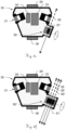
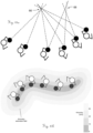
- Figures 2a-c show camera modules 30,30' being mounted on a pole 10 together with a position measuring resource of the respective surveying system.
- Each camera module 30,30' comprises an optical recording device 31 that is sensitive to light coming from all or many spatial directions. It could be based on an imaging sensor and a fish-eye lens, or a combination of a camera and a parabolic mirror, or a minimum of two single cameras arranged on a horizontal ring, or any other optical setup functioning as a wide-angle or panorama camera.
- the camera module can be a separate module 30 which is mounted on a pole 10 together with a GNSS antenna 15 ( Figure 2a ) or a reflector 16 ( Figure 2b ). Moreover, the module 30' can be integrated into the housing of a GNSS antenna ( Figure 2c ) or reflector.
- the camera module 30' is represented by the position measuring resource which additionally comprises a GNSS antenna and/or a reflector.
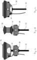
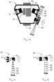
- the Figures 3a and 3b show a first embodiment of a camera module 30 according to the invention.
- the camera module 30 has a housing 40 and mounts for the pole 38 and for the position measuring resource 39 (GNSS antenna or reflector). It may comprise a set of cameras 31, e. g. four single cameras 31 aligned in angles of 90° to each other with a horizontal field-of-view >90°. In such an arrangement a horizontal field-of-view of 360° is covered.
- the vertical field-of-view (FOV) of the camera assembly can be about 60°.
- the cameras can be aligned horizontally or downward oriented, e. g. by 20°, as shown in Figure 3b . This is advantageous for applications where close objects are of particular interest.
- a processing unit 33 can be part of the camera module 30.
- the processing unit 33 can be a CPU, e. g. an ARM processor or a combination of a CPU with an FPGA, e. g. Zync SoC, or a combination of a CPU with a graphical-processing-unit (GPU).
- a combined processing unit e. g. feature tracking, etc. is carried out on the FPGA or the GPU.
- an inertial-measurement-unit (IMU) 34 can be part of the camera module.
- the IMU 34 may consist of a 3-axis accelerometer and, particularly, of a 3-axis gyroscope. Additionally, a magnetometer may be included in the IMU.
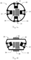
- FIGS. 4a and 4b show a second embodiment of a camera module 30 according to the invention:
- four downward-oriented cameras 31' can be combined with four upward oriented cameras 31".
- Figure 5a shows an arrangement with two fish-eye cameras 36 with a horizontal field-of-view of >180°
- Figure 5b shows an arrangement of a single camera 31 with a mirror 32, particularly a parabolic mirror, and a glass window 35.
- the cameras 31,31',31",36 of the camera modules 30 described above can have different resolutions.
- the camera module 30 comprises eight cameras, four cameras can have low resolution and are read-out in high frame rate (advantageous for feature tracking) and four cameras have high resolution (advantageous for dense matching) and are read-out with a lower frame rate.
- the high resolution cameras are not running with a specific frame rate but are triggered by the algorithm when a keyframe should be captured, e. g. in a distance interval of two meters.
- one single camera of the camera module is built so that image capturing with at least two different resolutions and/or different frame rates is provided by the camera.
- image capturing with at least two different resolutions and/or different frame rates is provided by the camera.
- a polarization filter can be mounted in front of the camera lenses (not shown here).
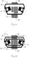
- FIGS. 6a and 6b show a two further embodiments of a camera module 30 having absorber means 37,37'.
- the relative position and orientation of the cameras 31 can be determined in a calibration procedure.
- an absorber 37 can be integrated, e. g. between the housing 40 and the mount for the pole 38, as shown in Figure 6a .
- the cameras 31 and the IMU 34 can be mounted on a frame 41 which is mechanically decoupled from the housing 40 by absorbers 37,37'.
- the absorbers 37 also reduce the maximum accelerations and avoid the accelerometers to saturate.
- damping element could be in form of a gimbal mounting or the like.
- image data is recorded with the camera module 30.
- the image data is recorded in parallel, i.e. synchronously.
- the trigger signal for triggering all the single cameras can be produced by another sensor, e. g. the GNSS antenna. Alternatively, one camera can trigger all the others.
- Image data can be recorded as a video with about 15 to 25 frames per second (FPS) or as a set of event-based triggered still images, e. g. an image is recorded when the operator moved two meters since the last image was taken. Alternatively, a new image can be captured, when the image content shows a significant difference to the previous image. Moreover, the recording of an image can be triggered by the operator, when he places the pole on a point and triggers a measurement.
- FPS frames per second
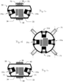
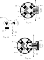
- FIGS 7a-c show two further embodiments of the camera module 30.
- Each camera module 30 comprises at least two cameras 31a-d and optical triggering means 70,71 for triggering a highly synchronous capturing of images by the cameras 31a-d. This is useful for instance to allow an image stitching of the images captured by the single cameras even if the camera module is in motion.
- a ring of flash lights 70 is arranged around the camera module 30, here around the mount for the position measuring resource 39.
- the cameras 31a,31b are adapted for perceiving a light flash from the flash lights 70 in the surrounding.
- the cameras 31a,31b then can synchronously capture an image.
- synchronously captured images of the cameras 31a,31b can be identified by the means of the light flash that appears in all images that have been captured during the flash.
- Figures 7b and 7c show a camera module 30 with four cameras 31a-d.
- the camera module 30 comprises optical triggering means designed as groups of light emitting diodes (LED) 71. These are arranged in such a way that each group 71 lies in the field-of-view (represented by dashed lines) of two of the cameras 31a-d and is perceivable by these two cameras.
- the groups of LED 71 can be used to trigger a highly synchronous capturing of images by the cameras 31a-d.
- the groups of LED 71 can also be used to add a code to the images, e. g. in order to allow identification of synchronously captured images.
- the scanning units 50 integrated in the camera module 30 are advantageous for the generation of point clouds in real-time, i.e. no expensive dense matching step has to be performed as in the case of point cloud generation with images. Moreover, in contrast to camera based approaches the scanning unit 50 does not rely on good textured surfaces for the derivation of point clouds.
- the scanning unit 50 can consist of a laser emitting and receiving unit 51 and a rotation mirror 52.
- the rotating laser beam 55 is spanning a more or less horizontal plane, if the pole is aligned more or less vertically.
- FIG 8b another setup of the scanning unit 50 is shown.
- the rotation axis of the mirror is tilted by about 10° to 30° from the horizontal plane.
- Figure 8c shows the camera module 30 of Figure 8b mounted on a surveying pole 10.
- the rotating laser 55 spans a laser plane which is tilted in such a way that it passes the GNSS antenna 15, and, consequently, the occlusions are small.
- the scanning module has to be somehow exposed.
- a drop protection 18 is mounted below the camera module 30 on the pole 10.
- Figure 8d shows a combination of a camera module 30 and a separate scanning module 58. Both modules 30,58 can be plugged together. For energy supply and data transfer a connector 59 can be integrated into the housing of each module 30,58.
- the scanning module 58 can be equipped with a separate processing unit 53. Alternatively, the computations of the scanning module 58 can be carried out on the processing unit 33 of the camera module 30.
- Figure 8e shows an integrated camera module 30 with a scanning unit 50' having a rotating laser emitting and receiving unit 51' instead of a rotating mirror.
- Figure 8f shows a camera module 30 with a scanning unit 50'' having a multi-beam setup with three laser emitting and receiving units 51' rotating together around one axis.
- the laser emitting and receiving unit can be mounted with an angular offset of 120°, e. g. like the blades of a wind turbine (not shown here).
- Figures 9a and 9b show an arrangement with two scanning units 50a,50b.
- the rotating beams 55a,55b of both of them span two tilted laser planes 56,56a ( Figure 9c ).
- the tilt angle influences the scanning resolution on the object, i.e. the density of the point cloud.
- an almost vertical plane scans the nearby ground in a (probably too) high resolution since the lever arm with about 2 m is quite short. Moreover, quite many rays are "wasted” since they are aimed to the sky.
- an almost horizontal plane does not cover the sky and the nearby ground at all.
- a combination of two scanning units where the rotation axis of one mirror is tilted by about 10° to 30° from the horizontal plane and the axis of the second mirror is tilted by about 10° to 30° from the vertical plane could lead to a improved distribution of the scanned points.
- the vertical angle of the laser plane can be made adjustable (this is shown in Figures 10a and 10b ). This enables the user to change the tilt angle according to his specific needs.
- the rotation can be continuous or there can be some predefined angles for high, medium and low. In the latter the scanning module clicks into the predefined positions.
- two scanning units 50a,50b which span almost vertical planes can be applied in such a way that there is a small horizontal angular offset of about 5 degrees.
- FIG. 9d -f An alternative embodiment is depicted in Figures 9d -f:
- the scanning unit 50′′′ comprises a plurality of laser emitting and receiving units 51.
- a fan of either diverging ( Figure 9e ) or parallel ( Figure 9f ) laser planes is generated.
- the scanning unit 50''''' can be integrated into the camera module 30 in such a way, that an unintended rotation of the pole can be compensated by a rotation of the scanning unit 50 ⁇ ′′′ into the opposite direction, in particular actuated by a drive 57.
- the rotation angle can be derived from measurements with the camera module 30, e. g. the angular rates from the IMU 34.
- the aim of the compensation can be that the azimuth of the laser plane is constant independently from the movements of the user.
- the scanning plane can automatically be aligned orthogonally to the walking direction of the user.
- the direction can for instance be derived from the state vector of the Kalman filter.
- the stabilization of the laser plane i.e. to keep the azimuth angle almost constant (smooth quick movements)
- a flying wheel 52'' rotates together with the mirror around the axis to be stabilized.
- FIG 11 a rotation of the camera to the left is illustrated with a moving object in the image.
- masking of different areas can be applied in order to remove undesired (here: moving) objects.
- This for instance include static objects relative to the pole like the surveyor itself as well as moving objects like pedestrians, cars and other non-static/relative static objects.
- the masking can be done semi-automatically with user interaction or fully automatically.
- a possible scenario for user interaction guided processing is the exclusion of the surveyor in tracking feature points on the images, where the user, for instance, roughly masks the outline of itself on the image and its silhouette is recognized and subsequently tracked by an appropriate algorithm (e. g. standard segmentation algorithms, active contours or template matching).
- a fully automated algorithm might detect interfering objects based on some motion estimation algorithms, e. g. optical flow, and reject the corresponding tracked features. For instance, as is shown in figure 11 , a rotation of the camera to the left would result in an optical flow indicated by the displayed arrows 111. Although becoming more complex by more advanced movements of the camera, this vector field (optical flow) can be used to determine moving objects - indicated by the displayed arrows 112 - within the image (e. g. by analyzing discontinuities or anomalies like inconsistent local changes) or even support segmentation or other image processing related algorithms.
- some motion estimation algorithms e. g. optical flow
- Possible variants of different procedures might include interfering object detection independently on each image, initial detection and tracking, as well as global motion elimination. Additionally, in order to become more robust, the final algorithm for removing moving objects (or corresponding inconsistent feature points) might consist of a multi-step procedure, e. g. local and global motion estimation. Since global motion in this context refers to camera movement, there might also be some additional sensor information (e. g. GNSS or IMU data) used, to predict global movement and, subsequently, to stabilize the detection of moving objects.
- additional sensor information e. g. GNSS or IMU data
- the detection of corresponding (interfering) features can be carried out on the processing unit in the camera module. Particularly, if an FPGA is included in the processing unit parts of the feature detection can be computed very efficiently on the FPGA.
- the poses of the images i.e. position and orientation
- This can be done for every image with a sufficiently large number of detected point features.
- processing power can be saved by selecting a subset of images and determine the pose only for those selected images.
- a criterion for the image selection can be the baseline, i.e. the distance between the current image and the previous one, e. g. a distance of one meter. Small baselines result in a bad accuracy of 3D points determined by forward intersection.
- Another criterion can be the image quality, i.e. only image with good quality (high sharpness, no under- or over-exposure, etc.) are selected.
- the image selection can be based on a combination of image data, IMU data and GNSS data or any subset of these data sources.
- the IMU could be used to select images that don't suffer from motion blur by considering the movement and especially the rotation during exposure. This has the advantage that blur-free images are selected even when the image content changes significantly.
- Different filters e. g. baseline and motion blur
- the low resolution cameras are mainly used for feature tracking in a high frame rate.
- images can be taken with varying exposure times, e. g. the images are taken with exposure times of 1 ms, 2 ms, 4 ms, 8 ms, 10 ms, 20 ms and so on.
- the image acquisition interval can be regular, i.e. an image in an interval of 8 ms.
- the image capture interval can be irregular.
- a HDR (high dynamic range) image can be generated based on a set of images captured with different exposure times. This can be done when the camera is held sufficiently still, which can be sensed with the IMU or GNSS or camera data or a combination of all. Alternatively, the camera can be moved and the offset determined with the structure-from-motion algorithm is considered in the generation of the HDR image.
- This feedback may include light indication (e. g. status LEDs), audio signals or force feedback (vibrating pole, smartwatches, vibration wristlet, smartphone, tablet, etc.).
- light indication e. g. status LEDs
- force feedback vibrating pole, smartwatches, vibration wristlet, smartphone, tablet, etc.
- directly visualize the current state of data recording e.g. on a mobile phone, tablet or special glasses (interactive glasses).
- SLAM simultaneous localization and mapping
- the determination of the 6-DoF is based on measurements from the camera and optionally additionally position measurements from the GNSS system (and/or total station with retro-reflector). Moreover, accelerations and angular rates measured with the IMU can also be included into the determination of the poses (i.e. position and orientation with 6 degree of freedom; i.e. 6-dof).
- the image data is analyzed for corresponding features (or corresponding/homologue image points), i.e. the position of the corresponding images of one identical object point 61 in several images. This is done using feature detection and matching algorithms such as SIFT, SURF, BRISK, BRIEF, etc.
- feature detection and matching algorithms such as SIFT, SURF, BRISK, BRIEF, etc.
- object points 61 are determined. These object points build up a reference point field, which can be used for each additionally gathered camera image as a reference, so that in each newly added image existing points of the reference point filed can be used to reference the image with respect to all previous images.
- corresponding image points in this added image and already previously existing images are found/identified for new object points of the surrounding.
- these found/identified corresponding image points in the newly added image and at least one "old" image i.e. the positions of the corresponding image points in the newly added image and the old image are used to determine coordinates of further object points by forward intersection, so that the reference point field is expanded therewith by the further object points.
- the pose can be determined (based on resection using existing feature/image point schemes of existing object points of the already existing reference point field) and, on the other hand (logically simultaneously), with each newly added image the reference point field is also growing (based on forward intersection using newly identified corresponding features/image points of previously unknown object points of the surrounding).
- the correspondences i.e. the corresponding or homologue image points or features
- a tracking algorithm on each video frame, e.g. by applying the Kanade-Lucas-Tomasi (KLT) feature tracker.
- KLT Kanade-Lucas-Tomasi
- the term of "capturing a series of images with one or more cameras” includes generating image data by consecutively (e.g. following a defined timing, like one image per second, or following a defined spacing, like one image every half meter of movement) capturing/taking single images or by capturing a video frame.
- reference point field which is a point cloud with comparatively low density (therefore also often called “sparse point cloud”)
- This reference point field is at first instance only computed so as to determine the poses of the images (i.e. so as to determine and reference the positions and orientations of the image-pickups relative to each other), i.e. at least initially only for localisation purposes.
- the reference point field thus, is a consecutively growing common reference frame for determining the poses.
- the reference point field usually does not comprise pre-known points of the surrounding.
- a relative pose algorithm is used to calculate the relative pose between two selected initial frames/images and an initial point cloud (i.e. a first part of the reference point field).
- IMU and/or GNSS data can be used additionally to determine the relative pose of the selected initial frames (so as to make the step of determining the poses more stable and/or more efficient).
- the pose of the third image can be computed by resection.
- forward intersection is applied to refine the 3D coordinates of the features detected in all three images and to determine new 3D points which are detected in one of the first images and the third one. Consequently, with added image new 3D points might be reconstructed and the number of points in the point cloud (reference point field) is growing ( fig. 13 ).
- a SLAM-evaluation with a defined algorithm using the series of images is performed, wherein a plurality of respectively corresponding image points are identified in each of several sub-groups of images of the series of images and, based on resection and forward intersection using the plurality of respectively corresponding image points,
- the overall solution i.e. the built up reference point field (i.e. the derived coordinates of the reference points) and the determined poses, and optionally also the determined image-positions of the corresponding image points in the images
- This algorithm is a non-linear least squares minimization of the re-projection error and optionally also the GNSS measurements. It will optimize the location and orientation of all camera poses and all 3D points of the reference point field in one step.
- Bundle-adjustment can be triggered by the user when he is using the pole to measure individual points, i.e. in traditional GNSS pole mode. Bundle-adjustment is then used to refine the location and orientation of the pole during the measurement to provide the user with an optimal estimate for the position of the tip during the measurement.
- image data, IMU data and/or GNSS data can be used to detect if the pole is held steady in one position. Bundle-adjustment is then triggered automatically. When an optimal - bundle-adjusted - result is available this is indicated to the user through e.g. a green light. The user can then immediately read out an optimal estimate for the position of the tip upon triggering a measurement.
- the position can be used in the resection of a new camera pose or in the computation of the relative pose the initial image pair.
- the detected feature positions in the image and the GNSS position are combined in the resection algorithm.
- the accuracies of the measurements e.g. 1 px for the feature measurements and 3 cm for GNSS positions, are considered and the measurements are weighted accordingly.
- GNSS geo-referenced and scaled point cloud
- GNSS delivers positions with good accuracy on a global scale
- the positions counteract the error accumulation and the resulting drift which might appear in SLAM based on image measurements only.
- the resection also works if no GNSS signal is available by image data only. This might be the case when the operator stands very close to a façade and most GNSS satellites are covered by the building.
- the 6-DoF are then derived by resection of the camera pose based on the existing point cloud.
- the derived position can be feed back to the GNSS module for a fast reacquisition of the fix for the GNSS position.
- the pose of the module can be determined also when the line-of-sight between total station and reflector is interrupted.
- the offset between the antenna centre and the camera module has to be considered.
- This offset might be known from the mechanical design or derived by calibration. When multiple cameras are used, their relative poses have to be calibrated or derived from the design as well. Calibration can be done by the manufacturer or by the user in a specially designed procedure using e.g. a well textured area (reference pattern) being capturable be the camera to be calibrated. A defined relative spatial relationship between the pattern and the camera is pre-known. The calibration can also be fine-tuned in the bundle adjustment (self-calibration).
- the data from the inertial measurement unit i.e. accelerations and angular rates
- IMU inertial measurement unit
- the accelerometer senses the gravity vector
- the tilt of the camera module i.e. the roll and pitch angle
- the horizontal orientation of the pole i.e. the yaw angle
- a magnetometer could be used to determine the yaw angle.
- the combination of the sensor data can be carried out by a sensor fusion algorithm, e. g. a Kalman filter, a particle filter etc.
- a sensor fusion algorithm e. g. a Kalman filter, a particle filter etc.
- the coordinates of the tip point can be derived. In practical surveying this has the advantage that the operator does not have to level the pole anymore after he places the tip point onto the measuring point. Because of the reduced time needed for measuring a single point, this has a positive impact on the productivity of the operator performing the measurement job.
- Dense matching has the goal to determine a dense point cloud, i.e. a 3D-coordinate for each pixel or a subset, e.g. on a regular 3 ⁇ 3 grid, i.e. for every 3rd pixel in row and column direction, in the original images.
- the algorithm consists of two major steps.
- a disparity map is computed. This map contains the offset of a pixel in two images, i.e. the shift to be applied to a pixel in the first image to end up at the position of the corresponding point in the second image.
- correlation techniques e. g. Semi-Global-Matching, etc.
- a confidence value can be obtained and used in the further processing, e. g. for adaptive weighting of the measurements.
- 3D points are computed by forward intersection. Knowing the pose of the image rays 60 from the projection centers through the corresponding pixels are set up. The 3D coordinates of the object point results from the intersection of these rays. In principle a minimum of two rays is needed for the intersection of a 3D point. However, in practice as many rays as available are used in the forward intersection.
- Identifying the image points (reference points) and determining poses for images based on the identified image points (particularly computing a point cloud based thereon) is a be understood as a form or at least part of a dense matching process.
- the 3D coordinates of the points are determined by minimizing the deviations - actually the squared deviations - between the point and all the rays.
- the quality of the intersection can be derived by computing the variance-covariance matrix and, furthermore, an estimate for the standard deviation of all three coordinates of the 3D point.
- a quality indicative output concerning the quality of at least one of the computed points of the point cloud as described above may be based on such computation.
- the final point cloud can be filtered using several criteria on the measurement quality. This includes the number of images where the point is observed, i.e. the number of rays used for the intersection, the baseline between the cameras which defines the geometry of the intersection, a measure for the consistency of all the measurements, etc.
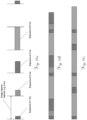
- a quality indicator can also be computed for an actually travelled path and actually acquired series of imaged (and also for a planned path with a planned capturing of images) solely base on pre-known circumstances like intrinsic factors (camera resolution, etc.) and general extrinsic factors (distance to camera, etc).
- a computation for the position of at least one point (and a consideration of a degree of intersection of the rays within the forward intersection) would not be necessary to for this estimated quality indicator.
- Figure 15b shows a visualisation of accuracy bounds (i.e. an accuracy map) based on an estimated reachable quality for the determination of 3d-positions in these regions. Points lying close to the planned or travelled trajectory have a higher estimated accuracy/quality and points of the surrounding lying farther from the planned or travelled trajectory have a lower estimated accuracy/quality.
- the operator places the tip point of the pole on the measuring point.
- the measurement of a dense point cloud is dynamic, i.e. the operator just walks around collecting data, i.e. image data, position data from GNSS or a total station, IMU data, etc.
- the user simply walks through the area to be mapped.
- the system records the image data, e.g. 15 frames per second, the GNSS positions and the IMU data.
- the sensors are either synchronized, e.g. triggered by a master sensor, or a time stamp is assigned to each measurement.
- a further inventive aspect is to de-blur images of the acquired series of images after computing "SLAM” (or as also called “Structure from Motion SfM”).
- a 3d-trajectory for the camera can be derived for the path travelled during acquisition of the series of images.
- a sparse point cloud for the scene/surrounding i.e. the positions of the reference point field for the surrounding extracted and used to derive the poses for the images
- SLAM algorithm is also already determined from the SLAM algorithm.
- a motion de-blurring can be performed in the images by image processing.
- imaged objects having been closer to the camera during acquisition of the image are applied with a comparatively higher degree/stage of motion de-blurring and imaged objects having been farther from the camera during acquisition of the image are applied with a comparatively lower degree/stage of motion de-blurring.
- de-blurred images After de-blurring of images of the acquired series of images, the newly generated imaged by de-blurring, which can be referred to as de-blurred images, can then substitute/replace the corresponding un-de-blurred images of the series of images.
- these de-blurred images can then constitute the series of images (i.e. then comprising only de-blurred images).
- the series of images can then consist of de-blurred images and un-de-blurred images.
- these newly or refreshed series of images then containing at least also some de-blurred images (or only de-blurred images) can be used for several purposes:
- both the positions of the reference points and the poses for the images can be determined more accurate and with less measurement uncertainty.
- either the refreshed/de-blurred series of images (comprising de-blurred images) can directly be used for the dense reconstruction.
- the step described under point a) above i.e. re-performing the SLAM-evaluation with the refreshed series
- the dense reconstruction can be performed using the de-blurred series and the already more accurately determined poses.
- SfM-/SLAM-evaluation on de-blurred images can provide for better results regarding the determination of the poses and the sparse point cloud, as features will be located with higher precision (and more features may be located) due to the higher contrast in the images. If the SfM is more precise, then further steps will provide better quality (dense reconstruction, meshing). But also without a refreshed SfM-/SLAM-evaluation in prefix, the dense reconstruction can be performed with at least somewhat higher quality by using the de-blurred images compared to the scenario of using un-de-blurred images.
- orthophoto 160 is generated by the surveying system and one is a reference orthophoto 165, for instance an aerial image.
- the term orthophoto here is understood as meaning a "true" orthophoto having an orthographic view, i.e. relief and tilt have been adjusted in order to orthorectify the image.
- the ground plane will be visible. Together with a known distance to the ground, camera locations and orientations, the images can be projected to the ground plane. By using many images from different directions, one large composite image of the ground plane can be computed. Due to the texture foreshortening (perspective effect, when cameras are looking at a certain angle to the ground), the method described in the paper "Analysis-by-Synthesis Texture Reconstruction" (Liefers, Parys, Schilling, 2012) can be used to obtain a high quality texture for the ground plane. The generated orthophoto can be registered to a georeferenced aerial image in order to localize the measurements in the geographic coordinate system. In the following paragraphs, the workflow is described in detail.
- the processing of the camera poses and the dense matching, i.e. the generation of the dense point cloud can be carried out on the processing unit as part of the camera module.
- the processing can be carried out on a controller (data logger) or the processing unit of the GNSS antenna which are connected to the camera module, either by a cable or via radio, Bluetooth, WiFi, etc.
- the data can be transmitted to a dedicated cloud server which is connected to the internet.
- the data can be transmitted directly from the camera module or via the controller or via the GNSS antenna.
- the server can be installed in a vehicle, e. g. a car which is located close to the surveying area and communicate with the pole through a local telecommunications protocol such as Bluetooth or WiFi.
- a vehicle e. g. a car which is located close to the surveying area and communicate with the pole through a local telecommunications protocol such as Bluetooth or WiFi.
- the server can be temporarily or permanently installed on site e. g. in a construction shed and communicate with the pole through a local telecommunications protocol.
- the transmission of the data and the processing on the cloud server starts immediately after the recording is started.
- the processing is carried out in parallel to the data acquisition in the background which helps to keep the latency of the result short.
- the system can include a second processing unit which is together with a power supply, e. g. batteries, carried by the operator in a backpack.
- the second processing unit may be equipped with a graphical processing unit (GPU) which enables massive parallel processing of the image data.
- the second processing unit can be a standard portable device such as a powerful laptop, tablet computer or smartphone.
- the second processing unit may communicate with the pole through cable or a local telecommunications protocol.
- a combination of processing on the processing unit of the camera module, the processing unit of the controller or the GNSS antenna and external processing units such as a cloud server can be carried out on the processing unit included in the camera module.
- a pre-processing of the image data e. g. the feature extraction or some basic image processing algorithms, can be carried out on this processing unit.
- the SLAM algorithm which results in the poses of the images and the coordinates of a sparse point cloud can be performed on the processing unit of the controller.
- the resulting camera poses and the images can then be transmitted to a cloud server where the dense matching is performed.
- the operator should receive already in the field a preview model shortly, e. g. a few minutes, after the data acquisition is finished. Based on this preview model the operator can decide whether he captured the measuring areas completely or whether some parts are uncovered. In the latter case the operator can take some additional measurements in the uncovered area to increase the level of completeness.
- the completeness check can be augmented with contrast analysis of the images in order to detect areas that are missing and for which it is unlikely that they will be reconstructed (uniform surfaces). This would save time of the user trying to reconstruct this kind of areas.
- the decision can be done by the operator on the basis of a visualization of the preview model, e. g. a 3D visualization.
- the visualization can be 2D as a map view, to present the user with a quicker and easier-to-understand view of the model compared with 3D models which are difficult to interpret and navigate for inexperienced users.
- the missing parts are high-lighted.
- the system can guide the operator to the area of missing measurements.
- the preview model should be available shortly after the data acquisition is finished.
- the preview model may have lower resolution than the final model, e. g. a point resolution on the object of 10 cm. This can be achieved by performing particularly the dense matching on images with lower resolution, e. g. after a reduction the image resolution from 1920 ⁇ 1080 pixels to 320 ⁇ 240 pixels.
- the processing is carried out on a cloud server the reduction of the image resolution is carried out before the data is transmitted.
- the image data can be compressed before they are sent to the processing server.
- the compression of image data can be carried out in a lossless way (i.e. a lossless data compression can be applied, without reducing the quality/resolution of the images) or in a lossy way (i.e., depending on the needs and circumstances of a particular situation, also a lossy data compression can be applied, including a reduction of the quality/resolution of the images).
- the data can be reduced (areas of very low contrast do not need to be transmitted) using sparse image representations.
- additional location information can be derived. This can be used as the only source of geo-location or can be coupled with GNSS or prism-based terrestrial measurements in order to improve geo-location accuracy.
- the SLAM algorithm is executed on the dataset.
- the structure from motion can use partial GNSS data, however this is not required.
- the orthophoto generation algorithm is executed. This algorithm works as follows:
- This approach can be used for an interactive visualization of the camera position on the map on the local device's screen.
- the local SLAM computations may be joined and optimized for a good fitting together in order to find relations between different sub-reconstructions with SLAM.
- the method can be used to create a geo-referenced orthomap for use in other applications without the need of renting a plane or a UAV.
- Figure 16a shows an example orthophoto 160 generated from the images acquired at the ground level. As it can be seen, those areas 162 not captured from the ground level, such as building roofs or tree tops, are not present.
- Figure 16b presents an example reference orthophoto 165 from a georeferenced aerial image. Those two images have a different scale and orientation. By using matching of scale and rotation of invariant features the generated image can be transformed to match the scale and rotation of the reference aerial image (the borders of the orthophoto 160 from Figure 16a are represented by the outline 166). This transformation is then used to bring the point cloud and positions of the measurement instrument to the coordinate system of the reference image 165.
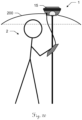
- the camera module can also be used without being combined with a GNSS system or a total station, in particular in applications where no absolute geo-referencing is needed. This is illustrated in Figure 17 .
- a 3D reconstruction without GNSS or total station might have an arbitrary scale.
- a state-of-the-art solution of this task is to use reference points with known 3D coordinates. These points are measured manually or automatically on the images. Their 3D coordinates are determined using additional measurement unit (e. g. with a total station). Alternatively, a scale bar could be used which is automatically identified in the image data.
- a user 2 could put the pole 10 onto the ground more than one time during the survey.
- the user could press a button on the pole to indicate the moment when the pole 10 is standing on the ground. Alternatively, this moment might be determined automatically based on comparison of sequentially recorded images or IMU information.
- the user could place the pole 10 on significant and marked points to be able to set the same coordinate system XYZ in the future (e. g. later in another survey).
- the height computation of the camera module 30 above the ground could be done manually or automatically in the reconstructed point cloud.
- a user selects points which belong to the ground.
- a height is extracted based on assumption that the pole 10 is oriented vertically.
- the height computation could also be performed in the meshed surface model.
- the GNSS data in combination with a panorama camera can be used to extend the standard SLAM approach in a new way.
- GNSS data can be used to select two frames recorded at roughly the same position but at different times. This happens when the user crosses his own path or takes the same path multiple times. Because a GNSS pole is held vertically under normal recording conditions, the main difference between the two frames is likely a horizontal rotation, i.e. a change in azimuth angle. Such a single rotation can be determined and compensated for efficiently using the raw images or detected feature points. After or during compensation of the azimuth change, optionally a compensation of the small change in the other two orientation angles can be performed in a similar way.
- a multitude of additional matches between the images can be found between the two frames by using a tracking algorithm such as KLT.
- the additional matches improve the connection between the two frames that are distant and time but not in position, i.e. loop closing. This stabilizes the algorithm and enhances the accuracy by further reducing drifts (also in rotation) for large datasets.
- Loop-closing is based on capturing a first series of images of the surrounding with the at least one camera, the first series comprising an amount of images captured with different poses of the cameras, the poses representing respective positions and orientations of the cameras. Furthermore, an initial set of image points is identified based on the first series of images, the initial image points representing reference points 62 of an initial reference point field 65 ( fig. 14 ), wherein each reference point appears in at least two images of the series of images, and the poses for the images are determined based on resection using the initial image points.
- a second series of images of the surrounding is captured with the at least one camera, reference points of the reference point field 65 appearing in at least one of the images of the second series of images are identified, a further set of image points is identified in the images of the second series of images corresponding to the identified reference points 62 of the second series of images, and the poses for the images of the second series of images are determined based on resection using the initial set and the further set of image points.
- the Figures 18 and 19a-d show two wheeled surveying systems that facilitate the surveying process for the user.
- the wheeled surveying system 180 depicted in Figure 18 comprises a pole 10 comprising the features of the pole of Figure 1 . Additionally, the pole 10 comprises wheels 181 that allow the user 2 to move the pole 10 along a path through the surrounding without having to carry the pole 10. To facilitate the pushing (or pulling) of the pole 10, it is equipped with a handle 182 (or two handles).
- two wheels 181 are attached to the pole 10 in such a way that the bottom end of the pole touches the ground if the pole is vertical (i.e. in a 90° angle relative to the ground). Even more preferably, the pole 10 keeps this upright position autonomously. For moving the pole 10 it needs to be tilted (as shown in Figure 18 ).
- the bottom end of the pole 10 can be extendable in order to touch the ground.
- the wheels 181 can be actuated by a motor, particularly an electric motor.
- This motor e. g. can either be controlled by the user 2 by a control unit on the handle 182 or can act as a support drive for the pushing (or pulling) movements of the user 2.
- the wheeled surveying system 190 depicted in Figures 19a-d comprises a two-wheeled, self-balancing motorized vehicle 195. This kind of vehicle is also widely known as "Segway personal transporter".
- the surveying system 190 comprises a pole 10 which is mounted on the vehicle 195. On the pole 10, as already described with respect to Figure 1 , a GNSS antenna 15 and a camera module 30 are provided.
- the surveying system 190 also comprises a control and evaluation unit 12.
- a motion of the vehicle 195 can be controlled by the user 2 as illustrated in Figures 19c and 19d :
- the depicted vehicle 195 is designed in such a way that the user 2 controls a forward and backward movement of the vehicle 195 by leaning the vehicle relative to a combined centre of gravity of user 2 and vehicle 195.
- the vehicle 195 can comprise measuring point marking means 192 that mark a spot on the ground as a present measuring point 5.
- this spot can be an imaginary extension of the pole 10.
- the marking can be a laser spot or pattern which lasts only for the stay at the respective position and is intended as information for the user 2 of the surveying system 190 driving the vehicle 195. In particular, this enables the user 2 to measure exactly at predefined marked positions.
- the marking can be more durable, for instance a sprayed paint marking or a dropped flag. This allows repeating the measurements at a later point of time at the same positions.
- an IMU of the vehicle 195 can be used for determining orientations of the cameras of the camera module 30 - either alternatively or additionally to an IMU of the camera module 30.
- the pole 10 can be equipped with a rain and/or sun protection, e. g. an umbrella being mounted below or around the GNSS antenna 15. This does not only facilitate the working conditions for the user 2 but also protects the camera module 30 and other features of the respective surveying system 1,180,190 and improves the image quality in case of precipitation.
- a rain and/or sun protection e. g. an umbrella being mounted below or around the GNSS antenna 15. This does not only facilitate the working conditions for the user 2 but also protects the camera module 30 and other features of the respective surveying system 1,180,190 and improves the image quality in case of precipitation.
Landscapes
- Engineering & Computer Science (AREA)
- Physics & Mathematics (AREA)
- General Physics & Mathematics (AREA)
- Radar, Positioning & Navigation (AREA)
- Remote Sensing (AREA)
- Multimedia (AREA)
- Signal Processing (AREA)
- Computer Vision & Pattern Recognition (AREA)
- Theoretical Computer Science (AREA)
- Computer Networks & Wireless Communication (AREA)
- Quality & Reliability (AREA)
- Manufacturing & Machinery (AREA)
- Length Measuring Devices By Optical Means (AREA)
- Studio Devices (AREA)
- Image Processing (AREA)
- Image Analysis (AREA)
Claims (13)
- Vermessungssystem (1), Folgendes umfassend- einen Vermessungsmast (10),- eine Anzeigeeinrichtung,- eine Positionsmesseinrichtung (15, 16), die auf dem Vermessungsmast (10) montiert ist, wobei die Positionen der Positionsmesseinrichtung durch das Vermessungssystem (1) ermittelbar sind, und- ein Vermessungs-Teilsystem,wobei das Vermessungs-Teilsystem ein Kameramodul (30) und eine Steuer- und Auswerteeinheit (12) umfasst,- wobei das Kameramodul (30) mindestens eine Kamera (31) zur Aufnahme von Bildern umfasst, die zur Befestigung am Vermessungsmast (10) ausgelegt ist,- wobei die Steuer- und Auswerteeinheit (12) ein Programm mit Programmcode zur Steuerung und Ausführung einer Fernpunkt-Messfunktion gespeichert hat, in derdadurch gekennzeichnet, dass- eine Serie von Bildern einer Umgebung mit der Kamera (31) aufgenommen wird, während sich das Vermessungssystem entlang eines Pfades durch die Umgebung bewegt, wobei die Serie eine Vielzahl von Bildern umfasst, die mit verschiedenen Kameraposen der Kamera aufgenommen wurden, d. h. von verschiedenen Punkten auf dem Pfad und mit verschiedenen Ausrichtungen der Kamera (31), und- eine SLAM-Auswertung mit einem definierten Algorithmus unter Verwendung der Bildserie, wobei eine Vielzahl von jeweils korrespondierenden Bildpunkten in jeder von mehreren Untergruppen von Bildern der Bildserie identifiziert wird und, basierend auf Rückwärtsschnitt und Vorwärtsschnitt unter Verwendung der Vielzahl von jeweils korrespondierenden Bildpunkten,• ein Referenzpunktfeld aufgebaut wird, das eine Vielzahl von Referenzpunkten der Umgebung umfasst, wobei die Koordinaten der Referenzpunkte abgeleitet werden und• die Kameraposen für die Bilder ermittelt werden,
die Steuer- und Auswerteeinheit (12) so konfiguriert ist, dass die Fernpunkt-Messfunktion derart gesteuert und ausgeführt wird, dass- ein Bild der Umgebung auf der Anzeigeeinrichtung des Vermessungssystems (1) angezeigt wird, wobei das Bild auf mindestens einem der Bilder der Bildserie basiert;- ein Bildpunkt im angezeigten Bild der Umgebung manuell von einem Benutzer auf der Anzeigeeinrichtung auswählbar ist,- bei der Auswahl des Bildpunkts eine 3D-Position des entfernten Punktes, der durch den ausgewählten Bildpunkt dargestellt wird, abgeleitet wird, wobei eine Teilmenge von Bildern, in denen der entfernte Punkt erscheint, automatisch aus der Bildserie identifiziert und die 3D-Position basierend auf dem Vorwärtsschnitt ermittelt wird unter Verwendung dieser Teilmenge von Bildern und der ermittelten Kameraposen für die Bilder dieser Teilmenge; und- die abgeleitete 3D-Position auf der Anzeigeeinrichtung bereitgestellt wird. - Vermessungssystem (1) nach Anspruch 1,
dadurch gekennzeichnet, dass
die Steuer- und Auswerteeinheit (12) so konfiguriert ist, dass die Fernpunkt-Messfunktion derart gesteuert und ausgeführt wird, dass die Teilmenge alle Bilder umfasst, in denen der entfernte Punkt erscheint. - Vermessungssystem (1) nach Anspruch 1 oder Anspruch 2,
dadurch gekennzeichnet, dass
die Positionsmesseinrichtung eine GNSS-Antenne (15) oder einen Rückstrahler (16) umfasst. - Vermessungssystem (1) nach einem der Ansprüche 1 bis 3,
dadurch gekennzeichnet, dass
die Steuer- und Auswerteeinheit (12) so konfiguriert ist, dass die Fernpunkt-Messfunktion derart gesteuert und ausgeführt wird, dass- ermittelte Positionen, die von der Positionsmesseinrichtung bei der Bewegung entlang des Pfads übernommen werden, von der Steuer- und Auswerteeinheit (12) aus dem Vermessungssystem (1) abgerufen werden, und- äußere Orientierungen der mindestens einen Kamera (31) im Koordinatensystem des Vermessungssystems (1), insbesondere in allen drei Rotationsfreiheitsgraden auf der Grundlage- der ermittelten Posen für die Bilder der Bildserie und- einer Vielzahl von ermittelten Positionen der Positionsmesseinrichtung abgeleitet werden. - Vermessungssystem (1) nach Anspruch 4,
dadurch gekennzeichnet, dass
die Positionen und äußeren Orientierungen der mindestens einen Kamera (31) im Koordinatensystem des Vermessungssystems (1) in sechs Freiheitsgraden abgeleitet werden. - Vermessungssystem (1) nach Anspruch 4 oder Anspruch 5,
dadurch gekennzeichnet, dass
die Vielzahl der ermittelten Positionen der Positionsmesseinrichtung eine Reisehistorie des begangenen Pfads umfasst. - Vermessungssystem (1) nach einem der Ansprüche 1 bis 6,
dadurch gekennzeichnet, dass
die Steuer- und Auswerteeinheit (12) so konfiguriert ist, dass die Fernpunkt-Messfunktion derart gesteuert und ausgeführt wird, dass Orientierungen der mindestens einen Kamera (31) auf der Grundlage einer oder mehrerer der ermittelten Posen und auf der Grundlage der von einer Trägheitsmesseinheit (34), während diese sich entlang des Pfads bewegt, erfassten Trägheitsmessdaten abgeleitet werden, wobei die Trägheitsmesseinheit dem Vermessungs-Teilsystem oder der Positionsmesseinrichtung (15, 16) in einer festen räumlichen Beziehung relativ zum Vermessungs-Teilsystem zugeordnet ist. - Vermessungssystem (1) nach einem der Ansprüche 1 bis 7,
dadurch gekennzeichnet, dass
die Steuer- und Auswerteeinheit (12) so konfiguriert ist, dass eine räumliche Darstellung der Umgebung erzeugt wird, wobei auf der Grundlage der ermittelten Posen eine dichte Punktwolke mit 3D-Positionen von Punkten der Umgebung durch Vorwärtsschnitt unter Verwendung der Bilder der Bildserie berechnet wird. - Vermessungssystem (1) nach Anspruch 8,
dadurch gekennzeichnet, dass
die dichte Punktwolke mit Hilfe der ermittelten Positionen skaliert wird, die von der Steuer- und Auswerteeinheit (12) aus dem Vermessungssystem (1) abgerufen werden, wobei die ermittelten Positionen die Positionen darstellen, die für die Positionsmesseinrichtung (15, 16) ermittelt werden, die von der Positionsmesseinrichtung bei der Bewegung entlang des Pfads übernommen wurden. - Vermessungssystem (1) nach Anspruch 8 oder Anspruch 9,
dadurch gekennzeichnet, dass
die Steuer- und Auswerteeinheit (12) so konfiguriert ist, dass für die dichte Punktwolke eine grafische Wiedergabe erzeugt wird, wobei die grafische Wiedergabe durch die Anzeigeeinrichtung des Vermessungssystems (1) darstellbar ist. - Vermessungssystem (1) nach einem der Ansprüche 1 bis 10,
dadurch gekennzeichnet, dass
das Kameramodul (30) mindestens vier, relativ zueinander angeordnete Kameras (31) umfasst, so dass Panoramabilder mit einem Sichtfeld von 360° in azimutaler Richtung erfasst werden können. - Vermessungssystem (1) nach Anspruch 11,
dadurch gekennzeichnet, dass
die mindestens vier Kameras (31) fest in einem gemeinsamen Gehäuse (40) des Kameramoduls (30) angeordnet sind. - Vermessungssystem (1) nach Anspruch 12,
dadurch gekennzeichnet, dass
eine Trägheitsmesseinheit (34) fest in dem gemeinsamen Gehäuse (40) des Kameramoduls (30) integriert ist.
Priority Applications (1)
| Application Number | Priority Date | Filing Date | Title |
|---|---|---|---|
| EP16202710.6A EP3228986B1 (de) | 2014-05-05 | 2014-05-05 | Vermessungssystem |
Applications Claiming Priority (3)
| Application Number | Priority Date | Filing Date | Title |
|---|---|---|---|
| EP16202710.6A EP3228986B1 (de) | 2014-05-05 | 2014-05-05 | Vermessungssystem |
| PCT/EP2014/059138 WO2015169338A1 (en) | 2014-05-05 | 2014-05-05 | Surveying system |
| EP14721402.7A EP3140613B1 (de) | 2014-05-05 | 2014-05-05 | Erfassungssystem |
Related Parent Applications (3)
| Application Number | Title | Priority Date | Filing Date |
|---|---|---|---|
| PCT/EP2014/059138 Previously-Filed-Application WO2015169338A1 (en) | 2014-05-05 | 2014-05-05 | Surveying system |
| EP14721402.7A Division EP3140613B1 (de) | 2014-05-05 | 2014-05-05 | Erfassungssystem |
| EP14721402.7A Division-Into EP3140613B1 (de) | 2014-05-05 | 2014-05-05 | Erfassungssystem |
Publications (2)
| Publication Number | Publication Date |
|---|---|
| EP3228986A1 EP3228986A1 (de) | 2017-10-11 |
| EP3228986B1 true EP3228986B1 (de) | 2024-03-13 |
Family
ID=50639549
Family Applications (10)
| Application Number | Title | Priority Date | Filing Date |
|---|---|---|---|
| EP16202706.4A Active EP3196594B1 (de) | 2014-05-05 | 2014-05-05 | Vermessungssystem |
| EP17191802.2A Pending EP3333541A3 (de) | 2014-05-05 | 2014-05-05 | Vermessungssystem |
| EP16202710.6A Active EP3228986B1 (de) | 2014-05-05 | 2014-05-05 | Vermessungssystem |
| EP16202708.0A Active EP3228984B1 (de) | 2014-05-05 | 2014-05-05 | Vermessungssystem |
| EP16202709.8A Pending EP3228985A1 (de) | 2014-05-05 | 2014-05-05 | Vermessungssystem |
| EP17191803.0A Pending EP3333542A1 (de) | 2014-05-05 | 2014-05-05 | Vermessungssystem |
| EP16202704.9A Pending EP3228983A1 (de) | 2014-05-05 | 2014-05-05 | Vermessungssystem |
| EP16202703.1A Pending EP3228982A1 (de) | 2014-05-05 | 2014-05-05 | Vermessungssystem |
| EP14721402.7A Active EP3140613B1 (de) | 2014-05-05 | 2014-05-05 | Erfassungssystem |
| EP19176410.9A Pending EP3569977A1 (de) | 2014-05-05 | 2014-05-05 | Vermessungssystem |
Family Applications Before (2)
| Application Number | Title | Priority Date | Filing Date |
|---|---|---|---|
| EP16202706.4A Active EP3196594B1 (de) | 2014-05-05 | 2014-05-05 | Vermessungssystem |
| EP17191802.2A Pending EP3333541A3 (de) | 2014-05-05 | 2014-05-05 | Vermessungssystem |
Family Applications After (7)
| Application Number | Title | Priority Date | Filing Date |
|---|---|---|---|
| EP16202708.0A Active EP3228984B1 (de) | 2014-05-05 | 2014-05-05 | Vermessungssystem |
| EP16202709.8A Pending EP3228985A1 (de) | 2014-05-05 | 2014-05-05 | Vermessungssystem |
| EP17191803.0A Pending EP3333542A1 (de) | 2014-05-05 | 2014-05-05 | Vermessungssystem |
| EP16202704.9A Pending EP3228983A1 (de) | 2014-05-05 | 2014-05-05 | Vermessungssystem |
| EP16202703.1A Pending EP3228982A1 (de) | 2014-05-05 | 2014-05-05 | Vermessungssystem |
| EP14721402.7A Active EP3140613B1 (de) | 2014-05-05 | 2014-05-05 | Erfassungssystem |
| EP19176410.9A Pending EP3569977A1 (de) | 2014-05-05 | 2014-05-05 | Vermessungssystem |
Country Status (4)
| Country | Link |
|---|---|
| US (11) | US10234287B2 (de) |
| EP (10) | EP3196594B1 (de) |
| CN (10) | CN109945844B (de) |
| WO (1) | WO2015169338A1 (de) |
Families Citing this family (160)
| Publication number | Priority date | Publication date | Assignee | Title |
|---|---|---|---|---|
| JP6455877B2 (ja) * | 2014-10-08 | 2019-01-23 | 株式会社トプコン | 測量装置 |
| EP3021079B1 (de) | 2014-11-14 | 2017-03-01 | Leica Geosystems AG | Geodätisches Erfassungssystem mit Visualisierung einer Aufgabenliste |
| EP3021078B1 (de) | 2014-11-14 | 2018-09-26 | Leica Geosystems AG | Geodätisches Erfassungssystem mit virtuellen Kamera |
| US10521472B2 (en) * | 2015-02-27 | 2019-12-31 | Realnetworks, Inc. | Composing media stories method and system |
| US10592914B2 (en) * | 2015-03-24 | 2020-03-17 | PlaceIQ, Inc. | Device-dwell graphs |
| EP3086283B1 (de) * | 2015-04-21 | 2019-01-16 | Hexagon Technology Center GmbH | Bereitstellung einer point-cloud unter verwendung eines vermessungsinstruments und einer kameravorrichtung |
| US10222932B2 (en) | 2015-07-15 | 2019-03-05 | Fyusion, Inc. | Virtual reality environment based manipulation of multilayered multi-view interactive digital media representations |
| US10242474B2 (en) | 2015-07-15 | 2019-03-26 | Fyusion, Inc. | Artificially rendering images using viewpoint interpolation and extrapolation |
| US11095869B2 (en) | 2015-09-22 | 2021-08-17 | Fyusion, Inc. | System and method for generating combined embedded multi-view interactive digital media representations |
| US11006095B2 (en) | 2015-07-15 | 2021-05-11 | Fyusion, Inc. | Drone based capture of a multi-view interactive digital media |
| JP6630515B2 (ja) * | 2015-08-25 | 2020-01-15 | 株式会社トプコン | 位置誘導装置、位置誘導方法、プログラム |
| US11783864B2 (en) | 2015-09-22 | 2023-10-10 | Fyusion, Inc. | Integration of audio into a multi-view interactive digital media representation |
| EP3165945B1 (de) | 2015-11-03 | 2024-01-03 | Leica Geosystems AG | Oberflächenvermessungsgerät zur bestimmung von 3d-koordinaten einer oberfläche |
| EP3391638A4 (de) * | 2015-12-16 | 2019-08-14 | Martineau, Pierre R. | Verfahren und vorrichtung zur remanenten bildgebungssteuerung |
| US20170178330A1 (en) * | 2015-12-17 | 2017-06-22 | Institute For Information Industry | System and method for interior mobile mapping |
| EP3182066B1 (de) * | 2015-12-17 | 2018-07-04 | Leica Geosystems AG | Vermessungsstab |
| WO2017107075A1 (en) * | 2015-12-22 | 2017-06-29 | SZ DJI Technology Co., Ltd. | System, method, and mobile platform for supporting bracketing imaging |
| TWI656692B (zh) * | 2015-12-31 | 2019-04-11 | 鴻海精密工業股份有限公司 | 通訊裝置 |
| WO2017130397A1 (ja) * | 2016-01-29 | 2017-08-03 | 富士通株式会社 | 位置推定装置、位置推定方法および位置推定プログラム |
| US10546385B2 (en) * | 2016-02-25 | 2020-01-28 | Technion Research & Development Foundation Limited | System and method for image capture device pose estimation |
| WO2017193165A1 (en) * | 2016-05-10 | 2017-11-16 | National Ict Australia Limited | Authenticating a user |
| US9940721B2 (en) * | 2016-06-10 | 2018-04-10 | Hand Held Products, Inc. | Scene change detection in a dimensioner |
| AU2017294795B2 (en) | 2016-07-15 | 2019-06-13 | Fastbrick Ip Pty Ltd | Boom for material transport |
| AU2017294796B2 (en) | 2016-07-15 | 2019-05-30 | Fastbrick Ip Pty Ltd | Brick/block laying machine incorporated in a vehicle |
| US10489927B2 (en) * | 2016-07-18 | 2019-11-26 | King Abdullah University Of Science And Technology | System and method for three-dimensional image reconstruction using an absolute orientation sensor |
| US10120075B2 (en) | 2016-08-19 | 2018-11-06 | Faro Technologies, Inc. | Using a two-dimensional scanner to speed registration of three-dimensional scan data |
| US10488195B2 (en) | 2016-10-25 | 2019-11-26 | Microsoft Technology Licensing, Llc | Curated photogrammetry |
| US10458792B2 (en) * | 2016-12-15 | 2019-10-29 | Novatel Inc. | Remote survey system |
| EP3339714A1 (de) * | 2016-12-20 | 2018-06-27 | Nokia Technologies Oy | Vorrichtung und zugehörige verfahren zur erfassung von bildern der virtuellen realität |
| US10563980B2 (en) * | 2016-12-23 | 2020-02-18 | Topcon Positioning Systems, Inc. | Enhanced remote surveying systems and methods |
| CN106705962B (zh) * | 2016-12-27 | 2019-05-07 | 首都师范大学 | 一种获取导航数据的方法及系统 |
| CN108268357B (zh) | 2016-12-30 | 2021-10-26 | 阿里巴巴集团控股有限公司 | 实时数据处理方法和装置 |
| US10437879B2 (en) | 2017-01-18 | 2019-10-08 | Fyusion, Inc. | Visual search using multi-view interactive digital media representations |
| JP6767279B2 (ja) | 2017-02-09 | 2020-10-14 | 株式会社トプコン | 測量システム |
| JP7355470B2 (ja) * | 2017-02-10 | 2023-10-03 | 株式会社トプコン | 測量装置、及び測量システム |
| CN106878597A (zh) * | 2017-03-06 | 2017-06-20 | 浙江大学 | 一种具有全景和特写功能的智能车载摄像机 |
| CN106932780A (zh) * | 2017-03-14 | 2017-07-07 | 北京京东尚科信息技术有限公司 | 物体定位方法、装置和系统 |
| US11032498B2 (en) * | 2017-03-17 | 2021-06-08 | The Regents Of The University Of Colorado, A Body | High speed two-dimensional imaging with an analog interface |
| CN110419209A (zh) * | 2017-03-31 | 2019-11-05 | 日本电气株式会社 | 信息处理装置、信息处理方法和信息处理程序 |
| US10200677B2 (en) * | 2017-05-22 | 2019-02-05 | Fyusion, Inc. | Inertial measurement unit progress estimation |
| US10237477B2 (en) * | 2017-05-22 | 2019-03-19 | Fyusion, Inc. | Loop closure |
| US10313651B2 (en) | 2017-05-22 | 2019-06-04 | Fyusion, Inc. | Snapshots at predefined intervals or angles |
| US10262243B2 (en) * | 2017-05-24 | 2019-04-16 | General Electric Company | Neural network point cloud generation system |
| CN108959321B (zh) * | 2017-05-25 | 2022-06-24 | 纵目科技(上海)股份有限公司 | 停车场地图构建方法、系统、移动终端及存储介质 |
| US11765323B2 (en) * | 2017-05-26 | 2023-09-19 | Calumino Pty Ltd. | Apparatus and method of location determination in a thermal imaging system |
| US10554957B2 (en) * | 2017-06-04 | 2020-02-04 | Google Llc | Learning-based matching for active stereo systems |
| US11392133B2 (en) * | 2017-06-06 | 2022-07-19 | Plusai, Inc. | Method and system for object centric stereo in autonomous driving vehicles |
| EP3415866B1 (de) * | 2017-06-12 | 2020-06-03 | Hexagon Technology Center GmbH | Vorrichtung, system und verfahren zur anzeige von messlücken |
| US11069147B2 (en) | 2017-06-26 | 2021-07-20 | Fyusion, Inc. | Modification of multi-view interactive digital media representation |
| EP3649616A4 (de) | 2017-07-05 | 2021-04-07 | Fastbrick IP Pty Ltd | Positions- und orientierungsverfolger in echtzeit |
| US10530997B2 (en) | 2017-07-13 | 2020-01-07 | Zillow Group, Inc. | Connecting and using building interior data acquired from mobile devices |
| US10375306B2 (en) | 2017-07-13 | 2019-08-06 | Zillow Group, Inc. | Capture and use of building interior data from mobile devices |
| DE102017117056A1 (de) * | 2017-07-27 | 2019-01-31 | Testo SE & Co. KGaA | Aufmaßgerät und Verfahren zur Erstellung eines 3D-Modells |
| WO2019026390A1 (ja) | 2017-08-01 | 2019-02-07 | ソニー株式会社 | 情報処理装置、情報処理方法、記録媒体、及び撮像装置 |
| CN107421754B (zh) * | 2017-08-08 | 2023-12-08 | 南京瑷卡测控技术有限公司 | 一种行人碰撞保护划线装置 |
| CN111226090B (zh) | 2017-08-17 | 2023-05-23 | 快砖知识产权私人有限公司 | 具有改进的横滚角测量的激光跟踪器 |
| CN111246976B (zh) | 2017-08-17 | 2024-03-15 | 快砖知识产权私人有限公司 | 交互系统配置 |
| GB2566523B (en) * | 2017-09-18 | 2020-02-26 | Jaguar Land Rover Ltd | System and method for vehicle convoys |
| WO2019071313A1 (en) | 2017-10-11 | 2019-04-18 | Fastbrick Ip Pty Ltd | MACHINE FOR CARRYING OBJECTS AND CARROUSEL WITH SEVERAL COMPARTMENTS FOR USE WITH THE SAME |
| US11709230B2 (en) * | 2017-10-12 | 2023-07-25 | John Matthews | Geodesic system and method of use |
| PT3477286T (pt) * | 2017-10-25 | 2023-04-24 | Hoffmann La Roche | Métodos e dispositivos para realizar uma medição analítica |
| RU178904U1 (ru) * | 2017-10-26 | 2018-04-23 | Иван Владимирович Чернов | Устройство определения азимута направления и местоположения |
| JP2021506052A (ja) * | 2017-12-07 | 2021-02-18 | アイフリー アシスティング コミュニケ−ション リミテッドEyeFree Assisting Communication Ltd. | コミュニケーション方法及びシステム |
| CN108318005A (zh) * | 2017-12-08 | 2018-07-24 | 上海工程技术大学 | 一种大型物体空间角度的测量装置 |
| CN108107462B (zh) * | 2017-12-12 | 2022-02-25 | 中国矿业大学 | Rtk与高速相机组合的交通标志杆姿态监测装置及方法 |
| CN108224008B (zh) * | 2017-12-22 | 2019-12-13 | 罗普特(厦门)科技集团有限公司 | 一种基于逐圈扫描广域全景成像光电转台装置 |
| US10657654B2 (en) * | 2017-12-28 | 2020-05-19 | Denso Ten Limited | Abnormality detection device and abnormality detection method |
| CN108510434B (zh) * | 2018-02-12 | 2019-08-20 | 中德(珠海)人工智能研究院有限公司 | 通过球幕相机进行三维建模的方法 |
| JP7232437B2 (ja) * | 2018-02-19 | 2023-03-03 | 国立大学法人 東京大学 | 作業車両の表示システム及び生成方法 |
| EP3543910B1 (de) * | 2018-03-19 | 2023-05-17 | Rosemount Aerospace Limited | Wolkenerkennung in der luftbildgebung |
| DE102018108141A1 (de) | 2018-04-06 | 2019-10-10 | Navvis Gmbh | Mobile Vorrichtung und Verfahren zum Erfassen eines Objektraums |
| US10643386B2 (en) | 2018-04-11 | 2020-05-05 | Zillow Group, Inc. | Presenting image transition sequences between viewing locations |
| KR102511533B1 (ko) * | 2018-04-24 | 2023-03-20 | 한화비전 주식회사 | 감시카메라용 렌즈어셈블리 및 이를 포함하는 감시 카메라 |
| US10592747B2 (en) | 2018-04-26 | 2020-03-17 | Fyusion, Inc. | Method and apparatus for 3-D auto tagging |
| US11656076B2 (en) * | 2018-05-15 | 2023-05-23 | Javad Gnss, Inc. | Method of calibrating a total station using a GNSS device |
| CN110545373B (zh) * | 2018-05-28 | 2021-12-28 | 中兴通讯股份有限公司 | 空间环境的感知方法及装置 |
| EP4036607A1 (de) | 2018-07-20 | 2022-08-03 | Trimble Nantes S.A.S. | Tragbare positionierungsvorrichtungen und verfahren zum erhalt einer geospatialen position |
| EP3598176A1 (de) | 2018-07-20 | 2020-01-22 | Trimble Nantes S.A.S. | Verfahren zur georäumlichen positionierung und tragbare positionierungsvorrichtungen dafür |
| TWI699705B (zh) * | 2018-08-06 | 2020-07-21 | 拓連科技股份有限公司 | 車輛之位置決定方法及系統,及其相關電腦程式產品 |
| EP3614299A1 (de) * | 2018-08-21 | 2020-02-26 | Siemens Aktiengesellschaft | Verfahren und anordnung zum erkennen von objekten an anlagen |
| EP3627100B1 (de) * | 2018-09-20 | 2021-12-01 | Hexagon Technology Center GmbH | Retroreflektor mit fischaugenobjektiv |
| WO2020069460A1 (en) * | 2018-09-28 | 2020-04-02 | Bounce Imaging, Inc. | Panoramic camera and image processing systems and methods |
| CA3058602C (en) | 2018-10-11 | 2023-01-24 | Zillow Group, Inc. | Automated mapping information generation from inter-connected images |
| US10708507B1 (en) | 2018-10-11 | 2020-07-07 | Zillow Group, Inc. | Automated control of image acquisition via use of acquisition device sensors |
| US10809066B2 (en) | 2018-10-11 | 2020-10-20 | Zillow Group, Inc. | Automated mapping information generation from inter-connected images |
| CN108981719B (zh) * | 2018-10-12 | 2024-03-01 | 中国空气动力研究与发展中心超高速空气动力研究所 | 一种超高速飞行模型位姿变化测量装置及方法 |
| US10380440B1 (en) | 2018-10-23 | 2019-08-13 | Capital One Services, Llc | Method for determining correct scanning distance using augmented reality and machine learning models |
| US11309947B2 (en) * | 2018-11-19 | 2022-04-19 | Facebook Technologies, Llc | Systems and methods for maintaining directional wireless links of motile devices |
| SE543047C2 (en) | 2018-12-04 | 2020-09-29 | Bjorkstrom Robotics Ab | A computer-implemented method, a computer program product, and an apparatus for facilitating placement of a surveying tool |
| CN109343572B (zh) * | 2018-12-20 | 2021-07-30 | 深圳市道通智能航空技术股份有限公司 | 一种无人机自主降落方法、装置及无人机 |
| WO2020137069A1 (ja) * | 2018-12-28 | 2020-07-02 | 株式会社Nttドコモ | 位置推定システム |
| US10958887B2 (en) * | 2019-01-14 | 2021-03-23 | Fyusion, Inc. | Free-viewpoint photorealistic view synthesis from casually captured video |
| EP3693698A1 (de) * | 2019-02-05 | 2020-08-12 | Leica Geosystems AG | Vermessungsgerät mit ereignisbasierter kamera |
| CN109859137B (zh) * | 2019-02-14 | 2023-02-17 | 重庆邮电大学 | 一种广角相机非规则畸变全域校正方法 |
| CN110044340B (zh) * | 2019-02-26 | 2021-06-29 | 中国一冶集团有限公司 | 半球形钢结构壳体尺寸测量控制方法 |
| US10616483B1 (en) * | 2019-02-27 | 2020-04-07 | Hong Kong Applied Science and Technology Research Institute Company Limited | Apparatus and method of generating electronic three-dimensional walkthrough environment |
| CN109947886B (zh) * | 2019-03-19 | 2023-01-10 | 腾讯科技(深圳)有限公司 | 图像处理方法、装置、电子设备及存储介质 |
| WO2020219982A1 (en) * | 2019-04-24 | 2020-10-29 | Nextvr Inc. | Methods and apparatus for encoding, communicating and/or using images |
| EP3734222A1 (de) * | 2019-05-02 | 2020-11-04 | Leica Geosystems AG | Koordinatenmess- und/oder absteckvorrichtung |
| CN110095752B (zh) * | 2019-05-07 | 2021-08-10 | 百度在线网络技术(北京)有限公司 | 定位方法、装置、设备和介质 |
| JP7202261B2 (ja) * | 2019-06-10 | 2023-01-11 | 株式会社トプコン | 測量装置 |
| RU192273U1 (ru) * | 2019-06-13 | 2019-09-11 | Александр Александрович Федоровский | Система наземной стереосъемки |
| CN110427026B (zh) * | 2019-07-15 | 2022-09-13 | 北京天时行智能科技有限公司 | 一种轮胎道路摩擦的确定方法及装置 |
| CN110274575A (zh) * | 2019-07-17 | 2019-09-24 | 伟志股份公司 | 一种基于gps技术的路线勘测系统及方法 |
| JP2022540679A (ja) * | 2019-07-17 | 2022-09-16 | メタウェーブ コーポレーション | ワイヤレス通信環境における増強されたアンテナ配置のための走査システム |
| CN110426674B (zh) * | 2019-07-17 | 2021-12-14 | 浙江大华技术股份有限公司 | 一种空间位置确定方法、装置、电子设备及存储介质 |
| US11250606B2 (en) * | 2019-07-31 | 2022-02-15 | Grabango Co. | Privacy protection in vision systems |
| DE102019120702A1 (de) * | 2019-07-31 | 2021-02-04 | Navvis Gmbh | Gestell für zumindest eine Scaneinrichtung und Raumerfassungsvorrichtung mit zumindest einer Scaneinrichtung |
| CN110440760B (zh) * | 2019-08-14 | 2022-05-20 | 散裂中子源科学中心 | 一种高精度摄影测量目标的制备方法 |
| US11808866B2 (en) | 2019-08-16 | 2023-11-07 | Javad Gnss, Inc. | Total station with GNSS device |
| US11566896B2 (en) * | 2019-08-22 | 2023-01-31 | Leica Geosystems Ag | Surveying system with image-based measuring |
| US11243656B2 (en) | 2019-08-28 | 2022-02-08 | Zillow, Inc. | Automated tools for generating mapping information for buildings |
| EP3788933A1 (de) * | 2019-09-05 | 2021-03-10 | BSH Hausgeräte GmbH | Verfahren zur steuerung eines haushaltsgeräts |
| CN110657782A (zh) * | 2019-09-20 | 2020-01-07 | 武汉大学 | 一种新型单镜头立体测绘装置及测绘方法 |
| US11164368B2 (en) | 2019-10-07 | 2021-11-02 | Zillow, Inc. | Providing simulated lighting information for three-dimensional building models |
| JP7314447B2 (ja) * | 2019-10-25 | 2023-07-26 | 株式会社トプコン | スキャナシステム及びスキャン方法 |
| DE102019216548A1 (de) * | 2019-10-28 | 2021-04-29 | DeepUp GmbH | Verfahren und mobile Erfassungsvorrichtung zur Erfassung von Infrastrukturelementen eines unterirdischen Leitungsnetzwerks |
| US11164361B2 (en) | 2019-10-28 | 2021-11-02 | Zillow, Inc. | Generating floor maps for buildings from automated analysis of visual data of the buildings' interiors |
| US10825247B1 (en) | 2019-11-12 | 2020-11-03 | Zillow Group, Inc. | Presenting integrated building information using three-dimensional building models |
| US11676344B2 (en) | 2019-11-12 | 2023-06-13 | MFTB Holdco, Inc. | Presenting building information using building models |
| US11295473B2 (en) * | 2019-12-18 | 2022-04-05 | Intel Corporation | Continuous local 3D reconstruction refinement in video |
| EP4078086A1 (de) * | 2019-12-19 | 2022-10-26 | Trimble Inc. | Oberflächennachführung mit mehreren kameras an einem mast |
| US11536857B2 (en) | 2019-12-19 | 2022-12-27 | Trimble Inc. | Surface tracking on a survey pole |
| US11175134B2 (en) * | 2019-12-19 | 2021-11-16 | Trimble Inc. | Surface tracking with multiple cameras on a pole |
| CN113093256B (zh) * | 2019-12-23 | 2024-02-13 | 上海华测导航技术股份有限公司 | 一种gnss/imu测绘系统和方法 |
| US11816855B2 (en) * | 2020-02-11 | 2023-11-14 | Samsung Electronics Co., Ltd. | Array-based depth estimation |
| CN111693725B (zh) * | 2020-06-01 | 2022-07-15 | 中光智控(北京)科技有限公司 | 一种瞄准目标运动角速率测量方法及装置 |
| US11405549B2 (en) | 2020-06-05 | 2022-08-02 | Zillow, Inc. | Automated generation on mobile devices of panorama images for building locations and subsequent use |
| US11436804B2 (en) * | 2020-06-10 | 2022-09-06 | Arm Limited | Augmented reality system |
| US11514674B2 (en) * | 2020-09-04 | 2022-11-29 | Zillow, Inc. | Automated analysis of image contents to determine the acquisition location of the image |
| US11592969B2 (en) | 2020-10-13 | 2023-02-28 | MFTB Holdco, Inc. | Automated tools for generating building mapping information |
| US11481925B1 (en) | 2020-11-23 | 2022-10-25 | Zillow, Inc. | Automated determination of image acquisition locations in building interiors using determined room shapes |
| CN112525107B (zh) * | 2020-11-24 | 2022-09-09 | 浙江知象光电科技有限公司 | 一种基于事件相机的结构光三维测量方法 |
| CN112489176B (zh) * | 2020-11-26 | 2021-09-21 | 香港理工大学深圳研究院 | 一种融合ESKF,g2o和点云匹配的紧耦合建图方法 |
| CN112434637B (zh) * | 2020-12-04 | 2021-07-16 | 上海交通大学 | 基于量子计算线路和LiDAR点云分类的物体识别方法 |
| CN112455726B (zh) * | 2020-12-10 | 2022-04-19 | 长光卫星技术股份有限公司 | 一种低轨光学遥感卫星多点成像快速机动控制方法 |
| EP4012334B1 (de) * | 2020-12-11 | 2023-10-18 | Leica Geosystems AG | Vermessungsstange und sekundärsensoreinheit mit toroidform |
| CN112747746A (zh) * | 2020-12-25 | 2021-05-04 | 珠海市一微半导体有限公司 | 基于单点tof的点云数据获取方法、芯片和移动机器人 |
| US11252329B1 (en) | 2021-01-08 | 2022-02-15 | Zillow, Inc. | Automated determination of image acquisition locations in building interiors using multiple data capture devices |
| CA3142154A1 (en) | 2021-01-08 | 2022-07-08 | Zillow, Inc. | Automated determination of image acquisition locations in building interiors using multiple data capture devices |
| CN112819943B (zh) * | 2021-01-15 | 2022-08-30 | 北京航空航天大学 | 一种基于全景相机的主动视觉slam系统 |
| US11790648B2 (en) | 2021-02-25 | 2023-10-17 | MFTB Holdco, Inc. | Automated usability assessment of buildings using visual data of captured in-room images |
| US11836973B2 (en) | 2021-02-25 | 2023-12-05 | MFTB Holdco, Inc. | Automated direction of capturing in-room information for use in usability assessment of buildings |
| CN112995484B (zh) * | 2021-03-17 | 2022-09-16 | 烟台业达智慧城市运营科技有限公司 | 一种基于人工智能的监控摄像头 |
| US11908198B2 (en) * | 2021-03-18 | 2024-02-20 | Pony Ai Inc. | Contextualization and refinement of simultaneous localization and mapping |
| EP4323969A2 (de) * | 2021-04-16 | 2024-02-21 | Hover Inc. | Systeme und verfahren zur erzeugung oder darstellung einer dreidimensionalen darstellung |
| TWI772020B (zh) * | 2021-05-12 | 2022-07-21 | 廣達電腦股份有限公司 | 影像定位裝置和方法 |
| EP4092379A1 (de) * | 2021-05-20 | 2022-11-23 | Hexagon Technology Center GmbH | Vermessungsvorrichtung mit bildauswerter zur bestimmung der räumlichen lage der zielachse |
| CN113552596A (zh) * | 2021-07-22 | 2021-10-26 | 中国十七冶集团有限公司 | 一种基于云边结合的新型gnss测量系统及测量方法 |
| US11501492B1 (en) | 2021-07-27 | 2022-11-15 | Zillow, Inc. | Automated room shape determination using visual data of multiple captured in-room images |
| CN113820735B (zh) * | 2021-08-31 | 2023-12-01 | 上海华测导航技术股份有限公司 | 位置信息的确定方法、位置测量设备、终端及存储介质 |
| US11842464B2 (en) | 2021-09-22 | 2023-12-12 | MFTB Holdco, Inc. | Automated exchange and use of attribute information between building images of multiple types |
| CN113847907A (zh) * | 2021-09-29 | 2021-12-28 | 深圳市慧鲤科技有限公司 | 定位方法及装置、设备、存储介质 |
| CN113933876B (zh) * | 2021-11-16 | 2023-05-23 | 西南电子技术研究所(中国电子科技集团公司第十研究所) | 多星通讯时差定位数据融合处理方法 |
| DE102021131129A1 (de) | 2021-11-26 | 2023-06-01 | Navvis Gmbh | Mobile vorrichtung und verfahren zum erfassen eines objektraums |
| CN114003045B (zh) * | 2021-12-30 | 2022-04-15 | 成都星宇融科电力电子股份有限公司 | 一种光电跟踪仪的目标跟踪方法、终端、可读存储介质 |
| AU2022200797A1 (en) * | 2022-02-04 | 2023-08-24 | Kelvin Chin Yeoh Lim | All seeing eyes housing system |
| CN114910933B (zh) * | 2022-03-10 | 2024-03-19 | 苏州天硕导航科技有限责任公司 | 带视觉测量功能的rtk接收机系统、板卡及测量方法 |
| US11830135B1 (en) | 2022-07-13 | 2023-11-28 | MFTB Holdco, Inc. | Automated building identification using floor plans and acquired building images |
| CN115829963B (zh) * | 2022-11-28 | 2023-11-03 | 江苏凯威特斯半导体科技有限公司 | 一种等离子喷涂图像数据识别分析方法和系统 |
Family Cites Families (32)
| Publication number | Priority date | Publication date | Assignee | Title |
|---|---|---|---|---|
| US5988862A (en) * | 1996-04-24 | 1999-11-23 | Cyra Technologies, Inc. | Integrated system for quickly and accurately imaging and modeling three dimensional objects |
| WO2000060853A1 (en) * | 1999-04-08 | 2000-10-12 | Internet Pictures Corporation | Method and apparatus for providing virtual processing effects for wide-angle video images |
| US20060012777A1 (en) | 2004-07-13 | 2006-01-19 | Talbot Nicholas C | Combination laser system and global navigation satellite system |
| US20060028550A1 (en) * | 2004-08-06 | 2006-02-09 | Palmer Robert G Jr | Surveillance system and method |
| US8415523B2 (en) * | 2005-04-16 | 2013-04-09 | Aalnex, Inc. | Secondary wound dressings for securing primary dressings and managing fluid from wounds, and methods of using same |
| US7541974B2 (en) | 2005-12-15 | 2009-06-02 | Trimble Navigation Limited | Managed traverse system and method to acquire accurate survey data in absence of precise GPS data |
| US8942483B2 (en) | 2009-09-14 | 2015-01-27 | Trimble Navigation Limited | Image-based georeferencing |
| JP5057734B2 (ja) | 2006-09-25 | 2012-10-24 | 株式会社トプコン | 測量方法及び測量システム及び測量データ処理プログラム |
| ES2327999B1 (es) * | 2007-08-06 | 2010-08-30 | Archidab Urban Media, S.L. | Procedimiento, programa de ordenador y archivo para generar imagenes que reproducen un entorno tridimensional real. |
| AU2014200772B2 (en) * | 2008-02-13 | 2015-12-17 | Caterpillar Inc. | Terrain map updating system |
| US8351684B2 (en) | 2008-02-13 | 2013-01-08 | Caterpillar Inc. | Terrain map updating system |
| DE112010000812T5 (de) | 2009-01-08 | 2012-06-06 | Trimble Navigation Limited | Verfahren und Systeme zum Bestimmen von Winkeln und Orten von Punkten |
| CN101487703B (zh) * | 2009-02-13 | 2011-11-23 | 浙江工业大学 | 快速全景立体摄像测量装置 |
| CN101561270B (zh) * | 2009-05-27 | 2011-05-04 | 天津理工大学 | 嵌入式全向球视觉目标检测和移动监控系统及方法 |
| US9879992B2 (en) | 2009-12-29 | 2018-01-30 | Trimble Inc. | Virtual perspective center aligned with measurement center |
| JP6002126B2 (ja) * | 2010-06-25 | 2016-10-05 | トリンブル ナビゲーション リミテッドTrimble Navigation Limited | 画像ベースの測位のための方法および装置 |
| CN102486376A (zh) * | 2010-12-04 | 2012-06-06 | 鸿富锦精密工业(深圳)有限公司 | 影像差异部位标注系统及方法 |
| CN102080969B (zh) | 2010-12-16 | 2012-07-11 | 哈尔滨工程大学 | 全景视觉测量系统安装位置快速校正装置 |
| EP2511781A1 (de) * | 2011-04-14 | 2012-10-17 | Hexagon Technology Center GmbH | System und Verfahren zur Steuerung eines unbemannten Fluggeräts |
| US9758239B2 (en) | 2011-04-14 | 2017-09-12 | Hexagon Technology Center Gmbh | System and method for controlling an unmanned air vehicle |
| US9109889B2 (en) * | 2011-06-24 | 2015-08-18 | Trimble Navigation Limited | Determining tilt angle and tilt direction using image processing |
| US9134127B2 (en) | 2011-06-24 | 2015-09-15 | Trimble Navigation Limited | Determining tilt angle and tilt direction using image processing |
| CN103438868B (zh) * | 2012-01-09 | 2015-09-09 | 刘进 | 基于球面全景相机的物体高度测量方法 |
| US9513120B2 (en) | 2012-09-20 | 2016-12-06 | Trimble Navigation Limited | Workflow improvements for stakeout |
| CN103017739B (zh) * | 2012-11-20 | 2015-04-29 | 武汉大学 | 基于激光雷达点云与航空影像的真正射影像的制作方法 |
| US9083960B2 (en) | 2013-01-30 | 2015-07-14 | Qualcomm Incorporated | Real-time 3D reconstruction with power efficient depth sensor usage |
| US9247239B2 (en) | 2013-06-20 | 2016-01-26 | Trimble Navigation Limited | Use of overlap areas to optimize bundle adjustment |
| EP2829842B1 (de) * | 2013-07-22 | 2022-12-21 | Hexagon Technology Center GmbH | Verfahren, system und computerprogrammprodukt zur bestimmung eines absoluten volumens einer halde mit einem structure-from-motion-algorithmus |
| CN103411587B (zh) * | 2013-08-14 | 2015-08-19 | 史云 | 定位定姿方法及系统 |
| US20150092048A1 (en) * | 2013-09-27 | 2015-04-02 | Qualcomm Incorporated | Off-Target Tracking Using Feature Aiding in the Context of Inertial Navigation |
| CN103644897B (zh) * | 2013-12-17 | 2016-01-13 | 中国科学院遥感与数字地球研究所 | 一种基于超分辨率影像重建的三维量测方法 |
| JP6062079B2 (ja) | 2014-05-30 | 2017-01-18 | エスゼット ディージェイアイ テクノロジー カンパニー リミテッドSz Dji Technology Co.,Ltd | 無人型航空輸送機(uav)の動作を制御するための制御器および方法ならびに乗り物 |
-
2014
- 2014-05-05 CN CN201811582495.8A patent/CN109945844B/zh active Active
- 2014-05-05 EP EP16202706.4A patent/EP3196594B1/de active Active
- 2014-05-05 CN CN201710846461.4A patent/CN107655461B/zh active Active
- 2014-05-05 EP EP17191802.2A patent/EP3333541A3/de active Pending
- 2014-05-05 WO PCT/EP2014/059138 patent/WO2015169338A1/en active Application Filing
- 2014-05-05 CN CN201710846198.9A patent/CN107727076B/zh active Active
- 2014-05-05 EP EP16202710.6A patent/EP3228986B1/de active Active
- 2014-05-05 CN CN201611120371.9A patent/CN106959103B/zh active Active
- 2014-05-05 EP EP16202708.0A patent/EP3228984B1/de active Active
- 2014-05-05 EP EP16202709.8A patent/EP3228985A1/de active Pending
- 2014-05-05 EP EP17191803.0A patent/EP3333542A1/de active Pending
- 2014-05-05 CN CN201611120364.9A patent/CN106908046B/zh active Active
- 2014-05-05 CN CN201611120367.2A patent/CN107084710B/zh active Active
- 2014-05-05 CN CN201480078610.1A patent/CN106461391B/zh active Active
- 2014-05-05 EP EP16202704.9A patent/EP3228983A1/de active Pending
- 2014-05-05 CN CN201611120164.3A patent/CN106959102B/zh active Active
- 2014-05-05 CN CN201611120366.8A patent/CN107101620B/zh active Active
- 2014-05-05 EP EP16202703.1A patent/EP3228982A1/de active Pending
- 2014-05-05 EP EP14721402.7A patent/EP3140613B1/de active Active
- 2014-05-05 US US15/308,827 patent/US10234287B2/en active Active
- 2014-05-05 EP EP19176410.9A patent/EP3569977A1/de active Pending
- 2014-05-05 CN CN201611120368.7A patent/CN106918331B/zh active Active
-
2016
- 2016-12-05 US US15/369,581 patent/US10359283B2/en active Active
- 2016-12-08 US US15/373,280 patent/US10274316B2/en active Active
- 2016-12-08 US US15/373,226 patent/US10655962B2/en active Active
-
2017
- 2017-09-28 US US15/719,368 patent/US10281276B2/en active Active
-
2018
- 2018-11-20 US US16/197,071 patent/US10371518B2/en active Active
-
2019
- 2019-01-22 US US16/253,522 patent/US10605601B2/en active Active
- 2019-04-17 US US16/387,398 patent/US10605602B2/en active Active
- 2019-04-26 US US16/396,528 patent/US10488198B2/en active Active
- 2019-04-29 US US16/398,101 patent/US10495461B2/en active Active
-
2020
- 2020-04-13 US US16/847,240 patent/US11054258B2/en active Active
Also Published As
Similar Documents
| Publication | Publication Date | Title |
|---|---|---|
| US11054258B2 (en) | Surveying system |
Legal Events
| Date | Code | Title | Description |
|---|---|---|---|
| PUAI | Public reference made under article 153(3) epc to a published international application that has entered the european phase |
Free format text: ORIGINAL CODE: 0009012 |
|
| STAA | Information on the status of an ep patent application or granted ep patent |
Free format text: STATUS: THE APPLICATION HAS BEEN PUBLISHED |
|
| AC | Divisional application: reference to earlier application |
Ref document number: 3140613 Country of ref document: EP Kind code of ref document: P |
|
| AK | Designated contracting states |
Kind code of ref document: A1 Designated state(s): AL AT BE BG CH CY CZ DE DK EE ES FI FR GB GR HR HU IE IS IT LI LT LU LV MC MK MT NL NO PL PT RO RS SE SI SK SM TR |
|
| AX | Request for extension of the european patent |
Extension state: BA ME |
|
| RIN1 | Information on inventor provided before grant (corrected) |
Inventor name: FIDLER, THOMAS Inventor name: VAN DER ZWAN, ELMAR VINCENT Inventor name: SCHEJA, JOCHEN Inventor name: SIERCKS, KNUT Inventor name: METZLER, BERNHARD Inventor name: VELIZHEV, ALEXANDER Inventor name: PARYS, ROMAN |
|
| STAA | Information on the status of an ep patent application or granted ep patent |
Free format text: STATUS: REQUEST FOR EXAMINATION WAS MADE |
|
| 17P | Request for examination filed |
Effective date: 20180410 |
|
| RBV | Designated contracting states (corrected) |
Designated state(s): AL AT BE BG CH CY CZ DE DK EE ES FI FR GB GR HR HU IE IS IT LI LT LU LV MC MK MT NL NO PL PT RO RS SE SI SK SM TR |
|
| RIN1 | Information on inventor provided before grant (corrected) |
Inventor name: SCHEJA, JOCHEN Inventor name: SIERCKS, KNUT Inventor name: VAN DER ZWAN, ELMAR VINCENT Inventor name: VELIZHEV, ALEXANDER Inventor name: PARYS, ROMAN Inventor name: METZLER, BERNHARD Inventor name: FIDLER, THOMAS |
|
| RIN1 | Information on inventor provided before grant (corrected) |
Inventor name: PARYS, ROMAN Inventor name: VAN DER ZWAN, ELMAR VINCENT Inventor name: FIDLER, THOMAS Inventor name: SCHEJA, JOCHEN Inventor name: SIERCKS, KNUT Inventor name: VELIZHEV, ALEXANDER Inventor name: METZLER, BERNHARD |
|
| RIN1 | Information on inventor provided before grant (corrected) |
Inventor name: PARYS, ROMAN Inventor name: VELIZHEV, ALEXANDER Inventor name: FIDLER, THOMAS Inventor name: SCHEJA, JOCHEN Inventor name: SIERCKS, KNUT Inventor name: VAN DER ZWAN, ELMAR VINCENT Inventor name: METZLER, BERNHARD |
|
| STAA | Information on the status of an ep patent application or granted ep patent |
Free format text: STATUS: EXAMINATION IS IN PROGRESS |
|
| 17Q | First examination report despatched |
Effective date: 20201007 |
|
| STAA | Information on the status of an ep patent application or granted ep patent |
Free format text: STATUS: EXAMINATION IS IN PROGRESS |
|
| REG | Reference to a national code |
Ref country code: DE Ref legal event code: R079 Free format text: PREVIOUS MAIN CLASS: G01C0015000000 Ipc: G01S0019140000 Ref country code: DE Ref legal event code: R079 Ref document number: 602014089712 Country of ref document: DE Free format text: PREVIOUS MAIN CLASS: G01C0015000000 Ipc: G01S0019140000 |
|
| RIC1 | Information provided on ipc code assigned before grant |
Ipc: G01C 25/00 20060101ALI20230725BHEP Ipc: H04N 23/63 20230101ALI20230725BHEP Ipc: H04N 23/55 20230101ALI20230725BHEP Ipc: G01S 19/42 20100101ALI20230725BHEP Ipc: G01C 15/00 20060101ALI20230725BHEP Ipc: G01S 19/14 20100101AFI20230725BHEP |
|
| GRAP | Despatch of communication of intention to grant a patent |
Free format text: ORIGINAL CODE: EPIDOSNIGR1 |
|
| STAA | Information on the status of an ep patent application or granted ep patent |
Free format text: STATUS: GRANT OF PATENT IS INTENDED |
|
| INTG | Intention to grant announced |
Effective date: 20231016 |
|
| GRAS | Grant fee paid |
Free format text: ORIGINAL CODE: EPIDOSNIGR3 |
|
| GRAA | (expected) grant |
Free format text: ORIGINAL CODE: 0009210 |
|
| STAA | Information on the status of an ep patent application or granted ep patent |
Free format text: STATUS: THE PATENT HAS BEEN GRANTED |
|
| AC | Divisional application: reference to earlier application |
Ref document number: 3140613 Country of ref document: EP Kind code of ref document: P |
|
| AK | Designated contracting states |
Kind code of ref document: B1 Designated state(s): AL AT BE BG CH CY CZ DE DK EE ES FI FR GB GR HR HU IE IS IT LI LT LU LV MC MK MT NL NO PL PT RO RS SE SI SK SM TR |
|
| REG | Reference to a national code |
Ref country code: GB Ref legal event code: FG4D |
|
| REG | Reference to a national code |
Ref country code: CH Ref legal event code: EP |
|
| REG | Reference to a national code |
Ref country code: DE Ref legal event code: R096 Ref document number: 602014089712 Country of ref document: DE |