EP3228564B1 - Convoyeur helicoidal et système de convoyage - Google Patents
Convoyeur helicoidal et système de convoyage Download PDFInfo
- Publication number
- EP3228564B1 EP3228564B1 EP16164444.8A EP16164444A EP3228564B1 EP 3228564 B1 EP3228564 B1 EP 3228564B1 EP 16164444 A EP16164444 A EP 16164444A EP 3228564 B1 EP3228564 B1 EP 3228564B1
- Authority
- EP
- European Patent Office
- Prior art keywords
- return section
- section portion
- upwardly directed
- helical
- conveyor belt
- Prior art date
- Legal status (The legal status is an assumption and is not a legal conclusion. Google has not performed a legal analysis and makes no representation as to the accuracy of the status listed.)
- Active
Links
Images


Classifications
-
- B—PERFORMING OPERATIONS; TRANSPORTING
- B65—CONVEYING; PACKING; STORING; HANDLING THIN OR FILAMENTARY MATERIAL
- B65G—TRANSPORT OR STORAGE DEVICES, e.g. CONVEYORS FOR LOADING OR TIPPING, SHOP CONVEYOR SYSTEMS OR PNEUMATIC TUBE CONVEYORS
- B65G15/00—Conveyors having endless load-conveying surfaces, i.e. belts and like continuous members, to which tractive effort is transmitted by means other than endless driving elements of similar configuration
- B65G15/04—Conveyors having endless load-conveying surfaces, i.e. belts and like continuous members, to which tractive effort is transmitted by means other than endless driving elements of similar configuration the load being carried on the lower run of the endless surface
-
- B—PERFORMING OPERATIONS; TRANSPORTING
- B65—CONVEYING; PACKING; STORING; HANDLING THIN OR FILAMENTARY MATERIAL
- B65G—TRANSPORT OR STORAGE DEVICES, e.g. CONVEYORS FOR LOADING OR TIPPING, SHOP CONVEYOR SYSTEMS OR PNEUMATIC TUBE CONVEYORS
- B65G21/00—Supporting or protective framework or housings for endless load-carriers or traction elements of belt or chain conveyors
- B65G21/16—Supporting or protective framework or housings for endless load-carriers or traction elements of belt or chain conveyors for conveyors having endless load-carriers movable in curved paths
- B65G21/18—Supporting or protective framework or housings for endless load-carriers or traction elements of belt or chain conveyors for conveyors having endless load-carriers movable in curved paths in three-dimensionally curved paths
-
- B—PERFORMING OPERATIONS; TRANSPORTING
- B65—CONVEYING; PACKING; STORING; HANDLING THIN OR FILAMENTARY MATERIAL
- B65G—TRANSPORT OR STORAGE DEVICES, e.g. CONVEYORS FOR LOADING OR TIPPING, SHOP CONVEYOR SYSTEMS OR PNEUMATIC TUBE CONVEYORS
- B65G15/00—Conveyors having endless load-conveying surfaces, i.e. belts and like continuous members, to which tractive effort is transmitted by means other than endless driving elements of similar configuration
- B65G15/60—Arrangements for supporting or guiding belts, e.g. by fluid jets
- B65G15/62—Guides for sliding belts
-
- B—PERFORMING OPERATIONS; TRANSPORTING
- B65—CONVEYING; PACKING; STORING; HANDLING THIN OR FILAMENTARY MATERIAL
- B65G—TRANSPORT OR STORAGE DEVICES, e.g. CONVEYORS FOR LOADING OR TIPPING, SHOP CONVEYOR SYSTEMS OR PNEUMATIC TUBE CONVEYORS
- B65G37/00—Combinations of mechanical conveyors of the same kind, or of different kinds, of interest apart from their application in particular machines or use in particular manufacturing processes
-
- B—PERFORMING OPERATIONS; TRANSPORTING
- B65—CONVEYING; PACKING; STORING; HANDLING THIN OR FILAMENTARY MATERIAL
- B65G—TRANSPORT OR STORAGE DEVICES, e.g. CONVEYORS FOR LOADING OR TIPPING, SHOP CONVEYOR SYSTEMS OR PNEUMATIC TUBE CONVEYORS
- B65G2207/00—Indexing codes relating to constructional details, configuration and additional features of a handling device, e.g. Conveyors
- B65G2207/24—Helical or spiral conveying path
Definitions
- the present invention relates to a helical conveyor, comprising a drivable endless conveyor belt having a transport section for transporting products where the conveyor belt follows at least partly a helical path between a lower end and an upper end of the transport section and a return section where the conveyor belt follows a path between the lower end and the upper end outside the transport section, a lower end reverse guide for turning the conveyor belt upside down and reverting its direction of movement between the transport section and the return section at the lower end of the transport section and an upper end reverse guide for turning the conveyor belt upside down and reverting its direction of movement between the transport section and the return section at the upper end of the transport section, wherein the return section leaves the upper end through a horizontally oriented upper return section portion and the return section leaves the lower end through a horizontally oriented lower return section portion.
- Helical conveyors are widely known in the prior art.
- a helical conveyor has an endless conveyor belt which follows a helical transport path for transporting products in vertical direction from an input at the lower end to an output at the upper end of the helical path and a return path along which the conveyor belt moves back from the output to the input.
- products may be supplied to the conveyor belt at the input and removed from the conveyor belt at the output, whereas the unloaded belt moves back from the output to the input.
- a typical known helical conveyor has its output at a higher level than its input. At the output the conveyor belt leaves the helical path and follows a straight horizontal path before it bends downwardly by an angle of 90° outside the helical path, as seen from above. After arriving at a height level near the input the conveyor belt bends again by an angle of 90° and follows a straight horizontal path extending parallel to and below the horizontal path at the output. Subsequently, the conveyor belt bends upwardly via a reverse roller and reverts at the input in order to follow the helical path from the input to the output.
- a drawback of the latter conveyor is the presence of a straight portion of the conveyor belt downstream of the output at the upper end of the helical path.
- the upper conveyor must have a horizontal displacement with respect to the lower conveyor due to the straight portion downstream the upper end of the helical path of the lower conveyor.
- two conveyor belts are applied parallel to each other, their straight portions lead to a difference between the linear speed and the rotational speed between the parallel conveyor belts, which may cause opposite friction forces onto products to be transported by both belts.
- JP H08 208015 discloses a helical conveyor according to the preamble of claim 1, in particular, the document is related to a spiral conveyor which spirally winds an endless belt body round a rotatable vertical tubular drive drum while making the belt body circulate and travel. A guide path body rotatable irrespective of the rotation of a drive drum is provided on the lower part of the drive drum to introduce a belt body.
- An object of the invention is to provide an improved helical conveyor.
- An advantage of the conveyor according to the invention is that the return section of the conveyor belt has a relatively short length, whereas the conveyor belt is turned upside down at the upper end and the lower end of the transport section such that straight portions at the upper and lower ends can be minimized. This means that the transport section can approach a real helical path.
- the upper and lower end reverse guides turn the conveyor belt upside down such that the conveyor belt moves in opposite direction before and after the upper and lower ends, respectively, as seen from above.
- the upper and lower end reverse guides may be rollers, possibly rollers including driving means for driving the conveyor belt.
- the term 'horizontally oriented' in the horizontally oriented upper and lower return section portions does not mean that these return section portions must extend exactly horizontally. They may be angled with respect to the horizontal plane, but in practice the angle may be smaller than 25°.
- the upper return section portion may have approximately the same inclination as the inclination of the helical path. An increasing angle could lead to a reduced space between the upper windings of the helical path.
- the lower end lies at an end of the helical path and the return section leaves the lower end tangentially as seen from above.
- the return section extends in outward direction from the helical path as seen from the lower end of the helical path.
- the conveyor belt follows an entirely helical path in the transport section.
- the upper and lower end reverse guides comprise rollers, there will be short but minimal straight portions at the upper and lower ends of the helical path.
- the upper and lower end reverse guides are at least partly located within the circumference of the helical path as seen from above.
- At least one of the upper return section portion, lower return section portion and upwardly directed return section portion bends within the plane of the conveyor belt. This provides the opportunity to have no or minimal twist of the conveyor belt in the return section.
- the upper and lower end reverse guides are located at opposite locations of the helical path as seen from above, and the upper and lower return section portions extend parallel to each other as seen from above, wherein the return section has a downwardly directed bend between the upper return section portion and the upwardly directed return section portion, on the one hand, and an upwardly directed bend between the lower return section portion and the upwardly directed return section portion, on the other hand, and wherein the upwardly directed return section portion forms an S-shaped path within the vertical plane.
- the conveyor belt must have an upper side and lower side which are both suitable for supporting and transporting articles, since its upper side and lower side alternatingly function as a transporting surface within the helical transport section under operating conditions.
- the upwardly directed bend may form a right angle between the lower return section portion and the upwardly directed return section portion, whereas the downwardly directed bend may form a right angle between the upper return section portion and the upwardly directed return section portion, respectively.
- At least one of the upper return section portion, lower return section portion and the upwardly directed return section portion twists about a longitudinal axis of the conveyor belt.
- the upper and lower end reverse guides are located at opposite locations of the helical path as seen from above, and the upper and lower return section portions extend parallel to each other as seen from above, wherein the return section has a downwardly directed bend between the upper return section portion and the upwardly directed return section portion, on the one hand, and an upwardly directed bend between the lower return section portion and the upwardly directed return section portion, on the other hand, wherein the upwardly directed return section portion follows an S-shaped path and twists by an angle of substantially 180°.
- the conveyor belt in the return section moves from the upper end to the lower end, it can bend downwardly at the end of the upper return section portion and follow the twisted and S-shaped upwardly directed return section portion towards the lower return section portion.
- the upwardly directed bend may form a right angle between the lower return section portion and the upwardly directed return section portion, whereas the downwardly directed bend may form a right angle between the upper return section portion and the upwardly directed return section portion, respectively.
- the radius of the downwardly directed bend between the upper return section portion and the upwardly directed return section portion may be larger than the radius of the upwardly directed bend between the lower return section portion and the upwardly directed return section portion. This allows to apply a conveyor belt which has a smaller minimum bending radius when it is bent about its lower side than when it is bent about its upper side, for example a slat belt of which the slats are movably coupled to a chain extending below the centres of the slats.
- the return section has an upwardly directed bend between the upper return section portion and the upwardly directed return section portion, on the one hand, and an upwardly directed bend between the lower return section portion and the upwardly directed return section portion, on the other hand, and the upwardly directed return section portion bends within the plane of the conveyor belt.
- the conveyor belt bends upwardly at the end of the upper return section portion remote from the upper end as well as at the end of the lower return section portion remote from the lower end, wherein the upwardly directed return section portion bends within the plane of the conveyor belt. This avoids the necessity of a twisted portion in the return section, whereas the conveyor belt can still always have the same orientation in the helical transport section.
- the upwardly directed return section portion may extend within a vertical plane and/or the upwardly directed return section portion may bend by an angle of 180°.
- the upper and lower end reverse guides are located at opposite locations of the helical path as seen from above, and the upper and lower return section portions extend parallel to each other as seen from above.
- One of the upwardly directed bends may form a right angle between the lower return section portion and the upwardly directed return section portion and/or the other one may form a right angle between the upper return section portion and the upwardly directed return section portion.
- the upper end of the transport section lies at an upper end of the helical path and the lower end of the transport section lies at a lower end of the helical path
- the conveyor belt is a first conveyor belt and the conveyor comprises a second drivable endless conveyor belt which extends parallel to the first conveyor belt.
- the first and second conveyor belt can be driven at the same angular speed within the transport section such that products do not move with respect to the first and second conveyor belt in the helical path, since the transport section forms substantially entirely a helical path. In the return section there will be a speed difference between the first and second conveyor belt.
- the invention is also related to a conveying system comprising at least two helical conveyors of the types as described above, wherein the helical conveyors are stacked onto each other such that the upper end of one of the conveyors is connected to the lower end of the other one.
- This provides the opportunity to create a high helical conveying system, which has a long total helical transport path or approximately a long total helical path, comprising separate conveyor belts, whereas the horizontal shift between two stacked conveyors is minimized due too minimal straight portions at the lower and upper end of the respective transport sections.
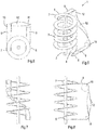
- Figs. 1-4 show a first embodiment of a helical conveyor 1 according to the invention.
- the conveyor 1 has 4.5 windings about a central column 2 and comprises a drivable endless conveyor belt 3 in the form of a slat belt, which has a plurality of slats, each including a longitudinal direction which extends transversely to the conveying direction.
- the conveyor belt 3 is supported and guided by a frame which is not shown for explanatory reasons.
- the conveyor belt 3 is driven by a driving means which is not shown.
- the slats of the conveyor belt 3 are movable with respect to each other such that the conveyor belt 3 can follow bends in a lateral direction within the plane of the conveyor belt 3 and in a direction perpendicularly to the plane of the conveyor belt 3.
- Each slat has an upper flat transport face and the slats are joined to each other so closely in the transport path that articles may be supported by a number of adjacent slats.
- the slats may be pivotally interconnected which allows to follow the path through the helical conveyor 1.
- the slats may be slightly tapered from their central axis to the ends, such that they do not interfere in curves.
- the conveyor belt 3 comprises a transport section for transporting products, where the conveyor belt 3 follows a helical path.
- the transport section extends between a lower end 4 and an upper end 5 of the helical path.
- the conveyor 1 is provided with a lower end reverse guide in the form of a lower end reverse roller 6 at the lower end 4 and an upper end reverse guide in the form of an upper end reverse roller 7 at the upper end 5 of the helical path.
- products may be placed onto the conveyor belt 3 at the lower end 4 of the helical path and follow the transport section upwardly to the upper end 5 of the helical path where they can leave the conveyor belt 3.
- the conveyor belt 3 also comprises a return section which extends between the upper end 5 and the lower end 4 outside the helical path.
- the return section comprises a non-helical path.
- the conveyor belt 3 is turned upside down by the upper end reverse roller 7 and the lower end reverse roller 6, respectively.
- an upper return section portion 8 leaving the helical path below the upper end 5 thereof and a lower return section portion 9 leaving the helical path below the lower end 4 thereof is created.
- the upper return section portion 8 and the lower return section portion 9 are straight and parallel to each other, both as seen from above as shown in Fig. 2 as well as seen from one side as shown in Fig. 4 and they extend horizontally.
- the upper return section portion 8 and the lower return section portion 9 leave the upper end 5 and lower end 4 tangentially, respectively, as seen from above.
- the upper end reverse roller 7 and the lower end reverse roller 6 are located at opposite sides of the helical path as seen from above. Their centrelines may lie in or close to a plane which is at or close to the central column 2 as illustrated in Fig. 4 , or their centrelines and the centreline of the central column 2 may substantially lie in the same plane. Their centrelines may be closer to a vertical plane when the dimensions of the rollers 6, 7 become smaller with respect to the radius of the helical path.
- the return section is provided with an upper guide roller 10 and a lower guide roller 11 which are located at the ends of the upper return section portion 8 and the lower return section portion 9, respectively.
- the upper and lower guide rollers 10, 11 have the same diameter and their centrelines lie in a common vertical plane. Consequently the return section has a right angle between the upper return section portion 8 and a upwardly directed return section portion 12, on the one hand, and a right angle between the lower return section portion 9 and the upwardly directed return section portion 12, on the other hand.
- the upwardly directed return section portion 12 lies below the upper return section portion 8 and above the lower return section portion 9.
- the upwardly directed return section portion 12 extends in a vertical plane and follows an S-shaped path within the vertical plane, see Fig. 3 . This means that the upwardly directed return section portion 12 of the conveyor belt 3 only bends within the plane of the conveyor belt 3 without any or any significant twist.
- the end portions of the S-shaped upwardly directed return section portion 12 are parallel to each other.
- the conveyor belt 3 of the embodiment as shown in Figs. 1-4 has an upper side and lower side which are both suitable for supporting and transporting articles, since its upper side and lower side alternatingly function as a transporting surface.
- the conveyor belt 3 follows the helical path upside down after each next cycle.
- the slats can be movably coupled to each other such that they are able to pull each other through the conveyor, for example a modular plastic belt. It may be clear that in this embodiment the slats cannot be mounted to a chain which extends at the centres of the slats below the slats, for example.
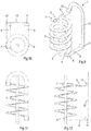
- Figs. 5-8 show a second embodiment of a helical conveyor 1 according to the invention.
- the second embodiment has a lot of similarities to the first embodiment and reference signs of corresponding parts are the same.
- the return section also follows a non-helical path and is guided by the upper guide roller 10 and the lower guide roller 11.
- the radius of the upper guide roller 10 is larger than the radius of the lower guide roller 11, the radius of the lower end reverse roller 6 and the radius of the upper end reverse roller 7, whereas the upwardly directed return section portion 12 is twisted by 180° about a longitudinal axis of the conveyor belt 3.
- the upwardly directed return section portion 12 lies below the upper return section portion 8 and above the lower return section portion 9.
- Fig. 7 illustrates that the upwardly directed return section portion 12 also has an S-shape as seen from one side.
- the end portions of the S-shaped upwardly directed return section portion 12 are parallel to each other; in this case they lie in the same vertical plane, see Fig. 8 .
- the upper side or the transporting surface of the conveyor belt 3 is directed upwardly in the helical transport section, directed downwardly in the upper return section portion 8, directed inwardly to the central column 2 of the helical path in the upper part of the upwardly directed return section portion 12, directed outwardly away from the helical path in the lower part of the upwardly directed return section portion 12, and directed downwardly in the lower return section portion 9. Due to the configuration of the embodiment as shown in Figs. 5-8 the upper side or the transporting surface of the conveyor belt 3 is always directed upwardly in the helical path.
- the diameter of the upper guide roller 10 is relatively large since the conveyor belt 3 as used in this embodiment has a smaller minimum bending radius when it is bent about its lower side than when it is bent about its upper side. This is typically the case when the lower sides of the slats of the conveyor belt 3 are mounted to a chain which is guided through a rail.
- Figs. 5-8 shows the upper guide roller 10 as being a roller, it is also possible that the conveyor belt 3 is only guided at its lower side through the right angle between the upper return section portion 8 and the upwardly directed return section portion 12 such that the upper guide roller 10 can be omitted.
- Figs. 9-12 show a third embodiment of a helical conveyor 1 according to the invention.
- the third embodiment has a lot of similarities to the first and second embodiments and reference signs of corresponding parts are the same.
- the return section also follows a non-helical path and is guided by the upper guide roller 10 and the lower guide roller 11. Contrary to the second embodiment the upwardly directed return section portion 12 is not twisted, but extends in a vertical plane.
- the diameter of the upper guide roller 10 is relatively small and in this case the same as the lower guide roller 11. This is possible with this configuration, in spite of the fact that the conveyor belt 3 of the third embodiment has also a smaller minimum bending radius when it is bent about its lower side than when it is bent about its upper side.
- the third embodiment provides the possibility to make a compact conveyor 1 in horizontal direction.
- the conveyor belt 3 is bent upwardly by the upper guide roller 10, at the end of the upper return section portion 8 remote from the upper end 5 of the helical path.
- the conveyor belt is also bent upwardly by the lower guide roller 11.
- the centrelines of the upper and lower guide rollers 10, 11 lie in a vertical plane. Consequently, the upwardly directed return section portion 12 also lies in a vertical plane and bends within the plane of the conveyor belt 3 by an angle of 180°.
- An advantage of the embodiments as shown in Figs. 1-12 is that the lower end reverse roller 6 and the upper end reverse roller 7 turn the conveyor belt upside down at the lower end 4 and the upper end 7 such that a real or almost real helical transport section is obtained including minimum straight portions at the lower and upper end 4, 5 thereof, whereas the return section is a non-helical, relatively short track. This minimizes required driving force.
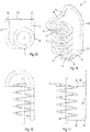
- Another advantage is that the conveyors 1 can be stacked on each other and coupled to each other such that a high total helical path is obtained. This is illustrated in Fig. 13 with three conveyors 1 of the type of the third embodiment according to Figs. 9-12 .
- Fig. 13 shows that the centreline of the middle conveyor 1 has a little horizontal displacement with respect to the upper and lower conveyor 1. However, the horizontal displacement will be reduced in case of upper and lower end reverse rollers 6, 7 which have a relatively small diameter with respect to the diameter of the helical path.
- the transition between the upper end 5 of one conveyor 1 and the lower end 4 of another conveyor 1 may have a wedge-shaped opening, as seen from above, which can be bridged by a guide plate or the like.
- Figs. 14-17 show an alternative embodiment of the third embodiment.
- the conveyor 1 has 4.75 windings about the central column 2.
- the upper return section portion 8 has a horizontal bend between the upper end 5 and the upper guide roller 10.
- Figs. 14-17 illustrate that numerous variations of the embodiments as described and shown herein are conceivable.
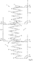
- Figs. 18-21 show still another alternative embodiment of the third embodiment.
- the conveyor 1 has two parallel conveyor belts 3a, 3b, which are driven at different linear speeds such that their angular speeds within the helical path are substantially equal. Consequently, products supported by both belts 3a, 3b do not move with respect to the first and second conveyor belt 3a, 3b in the helical path, since the belts more or less form a single wide conveyor belt. This is possible since the transport section forms substantially entirely a helical path with very short or without straight portions.
- the conveyor belt which follows the outer curve in the helical path is indicated by 3a and the other one is indicated by 3b.
- the other components of the conveyor are indicated by corresponding reference signs ending by a or b.
- the conveyor belt is twisted in the upper or lower return section portion rather than the upwardly directed return section portion.
- the transport section may have straight portions between the lower end thereof and the helical path. This means that the transport section is not entirely a helical path.
Landscapes
- Engineering & Computer Science (AREA)
- Mechanical Engineering (AREA)
- Structure Of Belt Conveyors (AREA)
Claims (14)
- Convoyeur hélicoïdal (1) comprenant une bande de convoyeur sans fin entraînable (3) présentant une section de transport pour le transport de produits où la bande de convoyeur suit au moins partiellement un trajet hélicoïdal entre une extrémité inférieure (4) et une extrémité supérieure (5) de la section de transport et une section de retour (8, 9, 12) où la bande de convoyeur (3) suit un trajet entre l'extrémité inférieure (4) et l'extrémité supérieure (5) en dehors de la section de transport, un guide à mouvement inversé d'extrémité inférieure (6) pour renverser la bande de convoyeur (3) et inverser sa direction de mouvement entre la section de transport et la section de retour au niveau de l'extrémité inférieure (4) de la section de transport et un guide à mouvement inversé d'extrémité supérieure (7) pour renverser la bande de convoyeur (3) et inverser sa direction de mouvement entre la section de transport et la section de retour au niveau de l'extrémité supérieure (5) de la section de transport, dans lequel la section de retour quitte l'extrémité supérieure (5) à travers une portion de section de retour supérieure orientée horizontalement (8) et la section de retour quitte l'extrémité inférieure (4) à travers une portion de section de retour inférieure orientée horizontalement (9), dans lequel la section de retour présente une portion de section de retour dirigée vers le haut (12) qui forme une connexion entre la portion de section de retour supérieure (8) et la portion de section de retour inférieure (9) et s'étend au moins partiellement en dehors du trajet hélicoïdal comme vu depuis le dessus, caractérisé en ce que l'extrémité supérieure (5) se trouve au niveau d'une extrémité du trajet hélicoïdal et la section de retour quitte l'extrémité supérieure (5) tangentiellement comme vu depuis le dessus et s'étend dans la direction vers l'extérieur depuis le trajet hélicoïdal comme vu depuis l'extrémité supérieure (5).
- Convoyeur hélicoïdal (1) selon la revendication 1, dans lequel l'extrémité inférieure (4) se trouve au niveau d'une extrémité du trajet hélicoïdal et la section de retour quitte l'extrémité inférieure (4) tangentiellement comme vu depuis le dessus.
- Convoyeur hélicoïdal (1) selon la revendication 1 ou 2, dans lequel au moins une de la portion de section de retour supérieure (8), la portion de section de retour inférieure (9) et la portion de section de retour dirigée vers le haut (12) se plie dans le plan de la bande de convoyeur (3).
- Convoyeur hélicoïdal (1) selon la revendication 3, dans lequel les guides à mouvement inversé d'extrémité supérieure et inférieure (7, 6) sont situés à des emplacements opposés du trajet hélicoïdal comme vu depuis le dessus, et dans lequel les portions de section de retour supérieure et inférieure (8, 9) s'étendent parallèlement l'une à l'autre comme vu depuis le dessus, dans lequel la section de retour présente un coude dirigé vers le bas entre la portion de section de retour supérieure (8) et la portion de section de retour dirigée vers le haut (12), d'une part, et un coude dirigé vers le haut entre la portion de section de retour inférieure (9) et la portion de section de retour dirigée vers le haut (12), d'autre part, dans lequel la portion de section de retour dirigée vers le haut (12) forme un trajet en forme de S dans le plan vertical.
- Convoyeur hélicoïdal (1) selon la revendication 1 ou 2, dans lequel au moins une de la portion de section de retour supérieure (8), la portion de section de retour inférieure (9) et la portion de section de retour dirigée vers le haut (12) est torsadée autour d'un axe longitudinal de la bande de convoyeur (3).
- Convoyeur hélicoïdal (1) selon la revendication 5, dans lequel les guides à mouvement inversé d'extrémité supérieure et inférieure (7, 6) sont situés à des emplacements opposés du trajet hélicoïdal comme vu depuis le dessus, et dans lequel les portions de section de retour supérieure et inférieure (8, 9) s'étendent parallèlement l'une à l'autre comme vu depuis le dessus, dans lequel la section de retour présente un coude dirigé vers le bas (10) entre la portion de section de retour supérieure (8) et la portion de section de retour dirigée vers le haut (12), d'une part, et un coude dirigé vers le haut (11) entre la portion de section de retour inférieure (9) et la portion de section de retour dirigée vers le haut (12), d'autre part, dans lequel la portion de section de retour dirigée vers le haut (12) suit un trajet en forme de S et est torsadée d'un angle de sensiblement 180°.
- Convoyeur hélicoïdal (1) selon la revendication 6, dans lequel le rayon du coude dirigé vers le bas (10) est supérieur au rayon du coude dirigé vers le haut (11).
- Convoyeur hélicoïdal (1) selon la revendication 1 ou 2, dans lequel la section de retour présente un coude dirigé vers le haut entre la portion de section de retour supérieure (8) et la portion de section de retour dirigée vers le haut (12), d'une part, et un coude dirigé vers le haut entre la portion de section de retour inférieure (9) et la portion de section de retour dirigée vers le haut (12), d'autre part, et dans lequel la portion de section de retour dirigée vers le haut (12) se plie dans le plan de la bande de convoyeur (3).
- Convoyeur hélicoïdal (1) selon la revendication 8, dans lequel la portion de section de retour dirigé vers le haut (12) s'étend dans un plan vertical.
- Convoyeur hélicoïdal (1) selon la revendication 8 ou 9, dans lequel la portion de section de retour dirigée vers le haut (12) se plie d'un angle de 180°.
- Convoyeur hélicoïdal (1) selon l'une des revendications 8 à 10, dans lequel les guides à mouvement inversé d'extrémité supérieure et inférieure (7, 6) sont situés à des emplacements opposés du trajet hélicoïdal comme vu depuis le dessus, et dans lequel les portions de section de retour supérieure et inférieure (8, 9) s'étendent parallèlement l'une à l'autre comme vu depuis le dessus.
- Convoyeur hélicoïdal (1) selon l'une des revendications 4, 6 à 11, dans lequel le coude dirigé vers le haut forme un angle droit entre la portion de section de retour inférieure (9) et la portion de section de retour dirigée vers le haut (12) et/ou entre la portion de section de retour supérieure (8) et la portion de section de retour dirigée vers le haut (12) et/ou le coude dirigé vers le bas forme un angle droit entre la portion de section de retour supérieure (8) et la portion de section de retour dirigée vers le haut (12).
- Convoyeur hélicoïdal (1) selon l'une des revendications précédentes, dans lequel l'extrémité supérieure (5) de la section de transport se trouve au niveau d'une extrémité supérieure du trajet hélicoïdal et l'extrémité inférieure (4) de la section de transport se trouve au niveau d'une extrémité inférieure du trajet hélicoïdal, dans lequel la bande de convoyeur est une première bande de convoyeur (3a) et le convoyeur (1) comprend une seconde bande de convoyeur sans fin entraînable (3b) qui s'étend parallèlement à la première bande de convoyeur (3a).
- Système de convoyage comprenant au moins deux convoyeurs hélicoïdaux (1) selon l'une des revendications précédentes, dans lequel les convoyeurs hélicoïdaux (1) sont empilés l'un sur l'autre de sorte que l'extrémité supérieure (5) d'un des convoyeurs soit raccordée à l'extrémité inférieure (4) de l'autre.
Priority Applications (7)
| Application Number | Priority Date | Filing Date | Title |
|---|---|---|---|
| ES16164444T ES2860930T3 (es) | 2016-04-08 | 2016-04-08 | Un transportador helicoidal y un sistema de transporte |
| ES21152218T ES2963007T3 (es) | 2016-04-08 | 2016-04-08 | Un transportador y un sistema de transporte |
| EP16164444.8A EP3228564B1 (fr) | 2016-04-08 | 2016-04-08 | Convoyeur helicoidal et système de convoyage |
| EP21152218.0A EP3825261B1 (fr) | 2016-04-08 | 2016-04-08 | Convoyeur et système de convoyage |
| CN201710217353.0A CN107265040B (zh) | 2016-04-08 | 2017-04-05 | 输送机及输送系统 |
| CN202110471827.0A CN113173373B (zh) | 2016-04-08 | 2017-04-05 | 输送机及输送系统 |
| US15/480,048 US10259654B2 (en) | 2016-04-08 | 2017-04-05 | Conveyor and a conveying system |
Applications Claiming Priority (1)
| Application Number | Priority Date | Filing Date | Title |
|---|---|---|---|
| EP16164444.8A EP3228564B1 (fr) | 2016-04-08 | 2016-04-08 | Convoyeur helicoidal et système de convoyage |
Related Child Applications (1)
| Application Number | Title | Priority Date | Filing Date |
|---|---|---|---|
| EP21152218.0A Division EP3825261B1 (fr) | 2016-04-08 | 2016-04-08 | Convoyeur et système de convoyage |
Publications (2)
| Publication Number | Publication Date |
|---|---|
| EP3228564A1 EP3228564A1 (fr) | 2017-10-11 |
| EP3228564B1 true EP3228564B1 (fr) | 2021-01-20 |
Family
ID=55750324
Family Applications (2)
| Application Number | Title | Priority Date | Filing Date |
|---|---|---|---|
| EP16164444.8A Active EP3228564B1 (fr) | 2016-04-08 | 2016-04-08 | Convoyeur helicoidal et système de convoyage |
| EP21152218.0A Active EP3825261B1 (fr) | 2016-04-08 | 2016-04-08 | Convoyeur et système de convoyage |
Family Applications After (1)
| Application Number | Title | Priority Date | Filing Date |
|---|---|---|---|
| EP21152218.0A Active EP3825261B1 (fr) | 2016-04-08 | 2016-04-08 | Convoyeur et système de convoyage |
Country Status (4)
| Country | Link |
|---|---|
| US (1) | US10259654B2 (fr) |
| EP (2) | EP3228564B1 (fr) |
| CN (2) | CN113173373B (fr) |
| ES (2) | ES2963007T3 (fr) |
Families Citing this family (4)
| Publication number | Priority date | Publication date | Assignee | Title |
|---|---|---|---|---|
| CN109018834A (zh) * | 2018-06-25 | 2018-12-18 | 宿松县春江粮油有限公司 | 一种用于大米生产的提升机 |
| CN109533867B (zh) * | 2018-12-30 | 2023-09-08 | 南京博蓝奇智能科技有限公司 | 分段独立控制输送机及输送系统 |
| CN109835656A (zh) * | 2019-04-12 | 2019-06-04 | 四方科技集团股份有限公司 | 输送带 |
| EP4324769B1 (fr) | 2022-08-16 | 2025-05-28 | Ambaflex International B.V. | Système de transport |
Citations (3)
| Publication number | Priority date | Publication date | Assignee | Title |
|---|---|---|---|---|
| DE20303097U1 (de) * | 2003-02-26 | 2003-05-15 | Heinen Freezing GmbH, 26316 Varel | Selbststapelnder Gurt |
| WO2010047867A1 (fr) * | 2008-10-21 | 2010-04-29 | Laitram, L.L.C. | Transporteur à courroie en spirale |
| WO2011156927A1 (fr) * | 2010-06-17 | 2011-12-22 | Wrh Walter Reist Holding Ag | Transporteur hélicoïdal |
Family Cites Families (12)
| Publication number | Priority date | Publication date | Assignee | Title |
|---|---|---|---|---|
| US1849237A (en) * | 1928-07-31 | 1932-03-15 | United Shoe Machinery Corp | Conveyer |
| JPS52155779A (en) * | 1976-06-18 | 1977-12-24 | Nippon Filcon Kk | Conveyor device |
| US4269302A (en) * | 1979-03-23 | 1981-05-26 | Garvey Corporation | Modular conveyor units and spiral conveyors constructed therefrom |
| DE3726059C1 (en) | 1987-08-06 | 1988-12-08 | Kloeckner Becorit Gmbh | Conveyor curve for a chain scraper conveyor |
| US4934517A (en) * | 1988-11-14 | 1990-06-19 | The Laitram Corporation | Horizontal flexing conveyor belt |
| JPH07157058A (ja) * | 1993-12-09 | 1995-06-20 | Toyo Kanetsu Kk | スパイラルコンベヤ |
| JPH08208015A (ja) * | 1995-02-01 | 1996-08-13 | Gunze Ltd | スパイラルコンベヤ |
| SE504530C2 (sv) * | 1996-04-11 | 1997-03-03 | Frigoscandia Equipment Ab | Bandtransportör |
| JP4498537B2 (ja) * | 2000-04-20 | 2010-07-07 | ウダカエンジニアリング株式会社 | スパイラルコンベヤ |
| EP1340698A1 (fr) | 2002-02-27 | 2003-09-03 | Rexnord Marbett S.p.A. | Guide pour transporteur d'articles |
| JP5448098B2 (ja) | 2007-09-17 | 2014-03-19 | ベー・エル・ハー・バルター・ライスト・ホウルディング・アクチェンゲゼルシャフト | 搬送システムのための偏向装置 |
| KR20120091048A (ko) * | 2009-09-04 | 2012-08-17 | 라이트람, 엘엘씨 | 스파이럴 컨베이어 시스템 및 방법 |
-
2016
- 2016-04-08 ES ES21152218T patent/ES2963007T3/es active Active
- 2016-04-08 ES ES16164444T patent/ES2860930T3/es active Active
- 2016-04-08 EP EP16164444.8A patent/EP3228564B1/fr active Active
- 2016-04-08 EP EP21152218.0A patent/EP3825261B1/fr active Active
-
2017
- 2017-04-05 CN CN202110471827.0A patent/CN113173373B/zh active Active
- 2017-04-05 US US15/480,048 patent/US10259654B2/en active Active
- 2017-04-05 CN CN201710217353.0A patent/CN107265040B/zh active Active
Patent Citations (3)
| Publication number | Priority date | Publication date | Assignee | Title |
|---|---|---|---|---|
| DE20303097U1 (de) * | 2003-02-26 | 2003-05-15 | Heinen Freezing GmbH, 26316 Varel | Selbststapelnder Gurt |
| WO2010047867A1 (fr) * | 2008-10-21 | 2010-04-29 | Laitram, L.L.C. | Transporteur à courroie en spirale |
| WO2011156927A1 (fr) * | 2010-06-17 | 2011-12-22 | Wrh Walter Reist Holding Ag | Transporteur hélicoïdal |
Also Published As
| Publication number | Publication date |
|---|---|
| CN113173373A (zh) | 2021-07-27 |
| ES2963007T3 (es) | 2024-03-22 |
| EP3825261C0 (fr) | 2023-09-06 |
| EP3825261B1 (fr) | 2023-09-06 |
| US10259654B2 (en) | 2019-04-16 |
| EP3228564A1 (fr) | 2017-10-11 |
| CN107265040B (zh) | 2021-06-11 |
| CN107265040A (zh) | 2017-10-20 |
| CN113173373B (zh) | 2023-03-31 |
| US20170291770A1 (en) | 2017-10-12 |
| ES2860930T3 (es) | 2021-10-05 |
| EP3825261A1 (fr) | 2021-05-26 |
Similar Documents
| Publication | Publication Date | Title |
|---|---|---|
| CN104854004B (zh) | 包括由桥轨连接的两条螺旋轨的输送机 | |
| US20100089724A1 (en) | Conveyor | |
| EP3228564B1 (fr) | Convoyeur helicoidal et système de convoyage | |
| CN107438573B (zh) | 具有传送带的输送系统 | |
| US8770376B2 (en) | Buffer conveyor for conveying and buffering products | |
| JPH01503379A (ja) | パイルとなって互いに重なる多数の巻回において螺旋状に動くエンドレスコンベアベルトに主として用いる備蓄装置 | |
| US9517897B2 (en) | System for repositioning flat-disposed objects | |
| MXPA01011680A (es) | Sistema tranportador helicoidal, dual, de baja tension. | |
| US20120103762A1 (en) | Conveyor with parallel conveyor members defining a helical path | |
| US8763787B2 (en) | Conveyor | |
| US20090032372A1 (en) | Strip Belt Conveyor | |
| JPH09124211A (ja) | 特にグラフィック製品又は出版製品を搬送するための方向変換装置 | |
| CN106163950B (zh) | 用于沿着竖直方向输送产品的输送机 | |
| US11186439B2 (en) | Chain conveyor curve | |
| US20110180373A1 (en) | Buffer conveyor for conveying and buffering products | |
| US11505409B2 (en) | Two-axis modular belt and conveyor | |
| CN105452144B (zh) | 用于运输人员和货物的通道托盘的安全链 | |
| KR100916599B1 (ko) | 스파이럴 컨베이어 | |
| JP4314941B2 (ja) | 搬送設備 | |
| CN118973927A (zh) | 侧向挠曲模块化输送带及其铰链销,以及在侧向挠曲模块化输送带中传递拉伸载荷的方法 |
Legal Events
| Date | Code | Title | Description |
|---|---|---|---|
| PUAI | Public reference made under article 153(3) epc to a published international application that has entered the european phase |
Free format text: ORIGINAL CODE: 0009012 |
|
| STAA | Information on the status of an ep patent application or granted ep patent |
Free format text: STATUS: THE APPLICATION HAS BEEN PUBLISHED |
|
| AK | Designated contracting states |
Kind code of ref document: A1 Designated state(s): AL AT BE BG CH CY CZ DE DK EE ES FI FR GB GR HR HU IE IS IT LI LT LU LV MC MK MT NL NO PL PT RO RS SE SI SK SM TR |
|
| AX | Request for extension of the european patent |
Extension state: BA ME |
|
| STAA | Information on the status of an ep patent application or granted ep patent |
Free format text: STATUS: REQUEST FOR EXAMINATION WAS MADE |
|
| 17P | Request for examination filed |
Effective date: 20180328 |
|
| RBV | Designated contracting states (corrected) |
Designated state(s): AL AT BE BG CH CY CZ DE DK EE ES FI FR GB GR HR HU IE IS IT LI LT LU LV MC MK MT NL NO PL PT RO RS SE SI SK SM TR |
|
| STAA | Information on the status of an ep patent application or granted ep patent |
Free format text: STATUS: EXAMINATION IS IN PROGRESS |
|
| 17Q | First examination report despatched |
Effective date: 20180725 |
|
| GRAP | Despatch of communication of intention to grant a patent |
Free format text: ORIGINAL CODE: EPIDOSNIGR1 |
|
| STAA | Information on the status of an ep patent application or granted ep patent |
Free format text: STATUS: GRANT OF PATENT IS INTENDED |
|
| INTG | Intention to grant announced |
Effective date: 20200916 |
|
| GRAS | Grant fee paid |
Free format text: ORIGINAL CODE: EPIDOSNIGR3 |
|
| GRAA | (expected) grant |
Free format text: ORIGINAL CODE: 0009210 |
|
| STAA | Information on the status of an ep patent application or granted ep patent |
Free format text: STATUS: THE PATENT HAS BEEN GRANTED |
|
| AK | Designated contracting states |
Kind code of ref document: B1 Designated state(s): AL AT BE BG CH CY CZ DE DK EE ES FI FR GB GR HR HU IE IS IT LI LT LU LV MC MK MT NL NO PL PT RO RS SE SI SK SM TR |
|
| REG | Reference to a national code |
Ref country code: GB Ref legal event code: FG4D |
|
| REG | Reference to a national code |
Ref country code: CH Ref legal event code: EP |
|
| REG | Reference to a national code |
Ref country code: DE Ref legal event code: R096 Ref document number: 602016051599 Country of ref document: DE |
|
| REG | Reference to a national code |
Ref country code: AT Ref legal event code: REF Ref document number: 1356214 Country of ref document: AT Kind code of ref document: T Effective date: 20210215 |
|
| REG | Reference to a national code |
Ref country code: IE Ref legal event code: FG4D |
|
| REG | Reference to a national code |
Ref country code: NL Ref legal event code: FP |
|
| REG | Reference to a national code |
Ref country code: SE Ref legal event code: TRGR |
|
| REG | Reference to a national code |
Ref country code: LT Ref legal event code: MG9D |
|
| PG25 | Lapsed in a contracting state [announced via postgrant information from national office to epo] |
Ref country code: PT Free format text: LAPSE BECAUSE OF FAILURE TO SUBMIT A TRANSLATION OF THE DESCRIPTION OR TO PAY THE FEE WITHIN THE PRESCRIBED TIME-LIMIT Effective date: 20210520 Ref country code: NO Free format text: LAPSE BECAUSE OF FAILURE TO SUBMIT A TRANSLATION OF THE DESCRIPTION OR TO PAY THE FEE WITHIN THE PRESCRIBED TIME-LIMIT Effective date: 20210420 Ref country code: BG Free format text: LAPSE BECAUSE OF FAILURE TO SUBMIT A TRANSLATION OF THE DESCRIPTION OR TO PAY THE FEE WITHIN THE PRESCRIBED TIME-LIMIT Effective date: 20210420 Ref country code: FI Free format text: LAPSE BECAUSE OF FAILURE TO SUBMIT A TRANSLATION OF THE DESCRIPTION OR TO PAY THE FEE WITHIN THE PRESCRIBED TIME-LIMIT Effective date: 20210120 Ref country code: GR Free format text: LAPSE BECAUSE OF FAILURE TO SUBMIT A TRANSLATION OF THE DESCRIPTION OR TO PAY THE FEE WITHIN THE PRESCRIBED TIME-LIMIT Effective date: 20210421 Ref country code: HR Free format text: LAPSE BECAUSE OF FAILURE TO SUBMIT A TRANSLATION OF THE DESCRIPTION OR TO PAY THE FEE WITHIN THE PRESCRIBED TIME-LIMIT Effective date: 20210120 Ref country code: LT Free format text: LAPSE BECAUSE OF FAILURE TO SUBMIT A TRANSLATION OF THE DESCRIPTION OR TO PAY THE FEE WITHIN THE PRESCRIBED TIME-LIMIT Effective date: 20210120 |
|
| PG25 | Lapsed in a contracting state [announced via postgrant information from national office to epo] |
Ref country code: PL Free format text: LAPSE BECAUSE OF FAILURE TO SUBMIT A TRANSLATION OF THE DESCRIPTION OR TO PAY THE FEE WITHIN THE PRESCRIBED TIME-LIMIT Effective date: 20210120 Ref country code: LV Free format text: LAPSE BECAUSE OF FAILURE TO SUBMIT A TRANSLATION OF THE DESCRIPTION OR TO PAY THE FEE WITHIN THE PRESCRIBED TIME-LIMIT Effective date: 20210120 Ref country code: RS Free format text: LAPSE BECAUSE OF FAILURE TO SUBMIT A TRANSLATION OF THE DESCRIPTION OR TO PAY THE FEE WITHIN THE PRESCRIBED TIME-LIMIT Effective date: 20210120 |
|
| PG25 | Lapsed in a contracting state [announced via postgrant information from national office to epo] |
Ref country code: IS Free format text: LAPSE BECAUSE OF FAILURE TO SUBMIT A TRANSLATION OF THE DESCRIPTION OR TO PAY THE FEE WITHIN THE PRESCRIBED TIME-LIMIT Effective date: 20210520 |
|
| REG | Reference to a national code |
Ref country code: DE Ref legal event code: R097 Ref document number: 602016051599 Country of ref document: DE |
|
| PG25 | Lapsed in a contracting state [announced via postgrant information from national office to epo] |
Ref country code: CZ Free format text: LAPSE BECAUSE OF FAILURE TO SUBMIT A TRANSLATION OF THE DESCRIPTION OR TO PAY THE FEE WITHIN THE PRESCRIBED TIME-LIMIT Effective date: 20210120 Ref country code: EE Free format text: LAPSE BECAUSE OF FAILURE TO SUBMIT A TRANSLATION OF THE DESCRIPTION OR TO PAY THE FEE WITHIN THE PRESCRIBED TIME-LIMIT Effective date: 20210120 Ref country code: SM Free format text: LAPSE BECAUSE OF FAILURE TO SUBMIT A TRANSLATION OF THE DESCRIPTION OR TO PAY THE FEE WITHIN THE PRESCRIBED TIME-LIMIT Effective date: 20210120 |
|
| PLBE | No opposition filed within time limit |
Free format text: ORIGINAL CODE: 0009261 |
|
| STAA | Information on the status of an ep patent application or granted ep patent |
Free format text: STATUS: NO OPPOSITION FILED WITHIN TIME LIMIT |
|
| PG25 | Lapsed in a contracting state [announced via postgrant information from national office to epo] |
Ref country code: DK Free format text: LAPSE BECAUSE OF FAILURE TO SUBMIT A TRANSLATION OF THE DESCRIPTION OR TO PAY THE FEE WITHIN THE PRESCRIBED TIME-LIMIT Effective date: 20210120 Ref country code: MC Free format text: LAPSE BECAUSE OF FAILURE TO SUBMIT A TRANSLATION OF THE DESCRIPTION OR TO PAY THE FEE WITHIN THE PRESCRIBED TIME-LIMIT Effective date: 20210120 Ref country code: SK Free format text: LAPSE BECAUSE OF FAILURE TO SUBMIT A TRANSLATION OF THE DESCRIPTION OR TO PAY THE FEE WITHIN THE PRESCRIBED TIME-LIMIT Effective date: 20210120 Ref country code: RO Free format text: LAPSE BECAUSE OF FAILURE TO SUBMIT A TRANSLATION OF THE DESCRIPTION OR TO PAY THE FEE WITHIN THE PRESCRIBED TIME-LIMIT Effective date: 20210120 |
|
| 26N | No opposition filed |
Effective date: 20211021 |
|
| PG25 | Lapsed in a contracting state [announced via postgrant information from national office to epo] |
Ref country code: LU Free format text: LAPSE BECAUSE OF NON-PAYMENT OF DUE FEES Effective date: 20210408 |
|
| PG25 | Lapsed in a contracting state [announced via postgrant information from national office to epo] |
Ref country code: AL Free format text: LAPSE BECAUSE OF FAILURE TO SUBMIT A TRANSLATION OF THE DESCRIPTION OR TO PAY THE FEE WITHIN THE PRESCRIBED TIME-LIMIT Effective date: 20210120 Ref country code: CH Free format text: LAPSE BECAUSE OF NON-PAYMENT OF DUE FEES Effective date: 20210430 Ref country code: LI Free format text: LAPSE BECAUSE OF NON-PAYMENT OF DUE FEES Effective date: 20210430 |
|
| PG25 | Lapsed in a contracting state [announced via postgrant information from national office to epo] |
Ref country code: SI Free format text: LAPSE BECAUSE OF FAILURE TO SUBMIT A TRANSLATION OF THE DESCRIPTION OR TO PAY THE FEE WITHIN THE PRESCRIBED TIME-LIMIT Effective date: 20210120 |
|
| PG25 | Lapsed in a contracting state [announced via postgrant information from national office to epo] |
Ref country code: IT Free format text: LAPSE BECAUSE OF FAILURE TO SUBMIT A TRANSLATION OF THE DESCRIPTION OR TO PAY THE FEE WITHIN THE PRESCRIBED TIME-LIMIT Effective date: 20210120 Ref country code: IE Free format text: LAPSE BECAUSE OF NON-PAYMENT OF DUE FEES Effective date: 20210408 |
|
| PG25 | Lapsed in a contracting state [announced via postgrant information from national office to epo] |
Ref country code: IS Free format text: LAPSE BECAUSE OF FAILURE TO SUBMIT A TRANSLATION OF THE DESCRIPTION OR TO PAY THE FEE WITHIN THE PRESCRIBED TIME-LIMIT Effective date: 20210520 |
|
| REG | Reference to a national code |
Ref country code: AT Ref legal event code: UEP Ref document number: 1356214 Country of ref document: AT Kind code of ref document: T Effective date: 20210120 |
|
| PG25 | Lapsed in a contracting state [announced via postgrant information from national office to epo] |
Ref country code: HU Free format text: LAPSE BECAUSE OF FAILURE TO SUBMIT A TRANSLATION OF THE DESCRIPTION OR TO PAY THE FEE WITHIN THE PRESCRIBED TIME-LIMIT; INVALID AB INITIO Effective date: 20160408 |
|
| PG25 | Lapsed in a contracting state [announced via postgrant information from national office to epo] |
Ref country code: CY Free format text: LAPSE BECAUSE OF FAILURE TO SUBMIT A TRANSLATION OF THE DESCRIPTION OR TO PAY THE FEE WITHIN THE PRESCRIBED TIME-LIMIT Effective date: 20210120 |
|
| PG25 | Lapsed in a contracting state [announced via postgrant information from national office to epo] |
Ref country code: MK Free format text: LAPSE BECAUSE OF FAILURE TO SUBMIT A TRANSLATION OF THE DESCRIPTION OR TO PAY THE FEE WITHIN THE PRESCRIBED TIME-LIMIT Effective date: 20210120 |
|
| PG25 | Lapsed in a contracting state [announced via postgrant information from national office to epo] |
Ref country code: MT Free format text: LAPSE BECAUSE OF FAILURE TO SUBMIT A TRANSLATION OF THE DESCRIPTION OR TO PAY THE FEE WITHIN THE PRESCRIBED TIME-LIMIT Effective date: 20210120 |
|
| PGFP | Annual fee paid to national office [announced via postgrant information from national office to epo] |
Ref country code: NL Payment date: 20250427 Year of fee payment: 10 |
|
| PGFP | Annual fee paid to national office [announced via postgrant information from national office to epo] |
Ref country code: DE Payment date: 20250429 Year of fee payment: 10 |
|
| PGFP | Annual fee paid to national office [announced via postgrant information from national office to epo] |
Ref country code: GB Payment date: 20250428 Year of fee payment: 10 Ref country code: ES Payment date: 20250505 Year of fee payment: 10 |
|
| PGFP | Annual fee paid to national office [announced via postgrant information from national office to epo] |
Ref country code: BE Payment date: 20250428 Year of fee payment: 10 |
|
| PGFP | Annual fee paid to national office [announced via postgrant information from national office to epo] |
Ref country code: FR Payment date: 20250425 Year of fee payment: 10 |
|
| PGFP | Annual fee paid to national office [announced via postgrant information from national office to epo] |
Ref country code: AT Payment date: 20250319 Year of fee payment: 10 |
|
| PGFP | Annual fee paid to national office [announced via postgrant information from national office to epo] |
Ref country code: SE Payment date: 20250430 Year of fee payment: 10 |
|
| PG25 | Lapsed in a contracting state [announced via postgrant information from national office to epo] |
Ref country code: TR Free format text: LAPSE BECAUSE OF FAILURE TO SUBMIT A TRANSLATION OF THE DESCRIPTION OR TO PAY THE FEE WITHIN THE PRESCRIBED TIME-LIMIT Effective date: 20210120 |