EP3226237A2 - Dispositif de diffusion sonore - Google Patents
Dispositif de diffusion sonore Download PDFInfo
- Publication number
- EP3226237A2 EP3226237A2 EP17160914.2A EP17160914A EP3226237A2 EP 3226237 A2 EP3226237 A2 EP 3226237A2 EP 17160914 A EP17160914 A EP 17160914A EP 3226237 A2 EP3226237 A2 EP 3226237A2
- Authority
- EP
- European Patent Office
- Prior art keywords
- sound
- inlet opening
- opening
- horn
- sound inlet
- Prior art date
- Legal status (The legal status is an assumption and is not a legal conclusion. Google has not performed a legal analysis and makes no representation as to the accuracy of the status listed.)
- Granted
Links
Images


Classifications
-
- G—PHYSICS
- G10—MUSICAL INSTRUMENTS; ACOUSTICS
- G10K—SOUND-PRODUCING DEVICES; METHODS OR DEVICES FOR PROTECTING AGAINST, OR FOR DAMPING, NOISE OR OTHER ACOUSTIC WAVES IN GENERAL; ACOUSTICS NOT OTHERWISE PROVIDED FOR
- G10K11/00—Methods or devices for transmitting, conducting or directing sound in general; Methods or devices for protecting against, or for damping, noise or other acoustic waves in general
- G10K11/02—Mechanical acoustic impedances; Impedance matching, e.g. by horns; Acoustic resonators
- G10K11/025—Mechanical acoustic impedances; Impedance matching, e.g. by horns; Acoustic resonators horns for impedance matching
-
- G—PHYSICS
- G10—MUSICAL INSTRUMENTS; ACOUSTICS
- G10K—SOUND-PRODUCING DEVICES; METHODS OR DEVICES FOR PROTECTING AGAINST, OR FOR DAMPING, NOISE OR OTHER ACOUSTIC WAVES IN GENERAL; ACOUSTICS NOT OTHERWISE PROVIDED FOR
- G10K13/00—Cones, diaphragms, or the like, for emitting or receiving sound in general
Definitions
- the present invention relates to a sound system having a sound generator which has a main emission direction, and a horn in the form of a hollow body which widens in a funnel shape from a sound inlet opening to a sound outlet opening and which has at least a first planar side surface extending between the openings Sounder is arranged at or near the sound inlet opening.
- Such sonicators are used to voice alarm people in areas with loud ambient noise.
- tunnels but also in other open and closed spaces, such as train stations, airports, factory buildings and shipyards, situations may arise in which persons must be informed about dangers and must be led out of the danger zones by means of voice instructions.
- Information, voice announcements or voice instructions can be transmitted via sound equipment arranged on the walls and especially on the ceilings of the rooms.
- the loud noise levels usually associated with the hazardous situations caused by, for example, fire, running machinery or engines or screaming people, must be drowned out by the sound system so that the possibly life-saving instructions can be perceived by the people to be evacuated acoustically understandable.
- the device should be simple and inexpensive to produce and versatile.
- a sound system with a sound generator which has a main emission direction, with a horn in the form of a funnel-shaped widening from a sound inlet opening to a sound outlet opening hollow body having at least a first extending between the openings, flat side surface, wherein the sound generator or near the sound inlet opening, and wherein the sound generator is arranged immediately adjacent to the (first) planar side surface or an imaginary extension thereof in such a way that its main radiation direction is parallel to the (first) planar side surface from the sound inlet to the sound exit opening ,
- the main radiation direction of a sound generator is defined by the direction of the respective maximum sound level of the free sounder or the sound-generating element thereof (which is, for example, a vibrating diaphragm) at an arbitrary distance (within a predetermined range).
- This definition of the main emission direction is intended to preclude reflection and change in direction of the sound waves emanating from the sound-generating element in front of or in the region of the sound inlet opening
- the sounder converts an electrical signal into an acoustic signal.
- the acoustic signal has a frequency range of 20 Hz to 20 kHz.
- the generated acoustic signal passes through the sound inlet opening in the horn of the sound system. Due to the arrangement of the sounder at or near the sound inlet opening occur almost no interactions between the acoustic signal and the sound inlet opening. The acoustic signal is passed almost lossless in the horn of the sound system.
- the sounder "on” or “near the sound inlet opening” is arranged when the sounder is disposed directly in the sound inlet opening adjoins this or at a distance along the Hauptabstrahlraum having the order of the maximum diameter of the Sound inlet is or is smaller.
- the arrangement of the sound generator at or near the sound inlet orifice pursues the purpose of introducing the acoustic signal through the sound inlet into the horn and through it with virtually no loss, without intermediate deflection or backscattering of the sound waves emanating from the actual sound source (eg vibrating membrane) ,
- the distance of the sounder to the sound inlet opening should not exceed a value of 50 mm and preferably 1 mm or less.
- the horn-introduced acoustic signal propagates in the funnel-shaped horn in the form of sound waves. Because the sound generator is disposed immediately adjacent to the flat side surface and the main radiation direction of the sounder is parallel to the flat side surface from the sound entrance opening to the sound exit opening, the maximum (the maximum amplitude) of the wavefront propagates parallel to this flat side surface.
- This side surface may for example be mounted parallel to a wall or ceiling of a building.
- the generated sound pressure in the direction of radiation is not weakened by the flat side surface of the horn and corresponding walls or ceilings but by reflections at a very small angle, which cause no noticeable transit time differences, rather amplified, so that the acoustic signal is good and undistorted perceptible even at a great distance.
- immediateately adjacent to the flat side surface or an imaginary extension thereof is understood to mean that the sound generator is arranged as close as possible to the flat side surface.
- the sounder touches the flat side surface or its imaginary extension.
- a clear distance of up to 4 cm, preferably of at most 2 cm, between the sound generator and the flat side surface or its extension is understood, for example, as "immediately adjacent to the flat side surface or an imaginary extension thereof".
- the sound generator has a membrane whose main vibration direction corresponds to the main emission direction.
- the projection surface of the membrane measured perpendicularly to the main emission direction should then largely (more than 50%), preferably completely cover the cross-section of the sound entry opening. If the surface of the membrane projected in a plane perpendicular to the main emission direction is smaller than the cross section of the sound inlet opening, the surface of the membrane projected into the cross section of the sound inlet opening should adjoin the plane defined by the flat side surface of the horn or have at most a clear distance to this plane , which is less than half the maximum diameter of the projection surface of the membrane.
- the projection surface of such a vibrating membrane on the sound inlet opening may also be larger than the surface of the sound inlet opening, but should not be more than twice.
- the sound inlet opening is circular, wherein preferably the edge of the sound inlet opening, the flat side surface or an imaginary extension of the flat side surface tangent.
- the sound generator preferably has a circular or rotationally symmetrical membrane as a sound-generating element.
- the projected along the main emission in a plane perpendicular to this plane of the membrane is then in the sound inlet opening 5, or covers it.
- the symmetry axis of the membrane and the main emission direction then also coincide.
- the opening cross section of the sound outlet opening and the opening cross section of the sound inlet opening in each case perpendicular to the main emission, a ratio between 10: 1 and 500: 1, preferably between 50: 1 and 200: 1, particularly preferably 180: 1.
- the free (inner) cross section of the horn is rectangular, with the inner corners preferably having a radius of curvature of a few millimeters.
- the horn may have in its initial section, starting from the sound inlet opening of the shape of the sounder or its membrane adapted cross-section, so for example a circular cross-section, which then gradually, for example, within the first tenth of the horn length, merges into a rectangular cross-section. In this initial region, the above-defined flat surface of the horn would not be exactly flat, but would be a tangent to the cross section of the horn in this plane.
- At least one second side surface of the horn connecting the sound inlet opening and the sound outlet opening is arranged opposite to the first planar side surface which is not flat, but for example curved concavely outwards from the sound inlet opening to the sound outlet opening so that the free cross section of the horn progressively increases in the direction of the sound outlet opening.
- the axis of curvature lies parallel to the first plane and perpendicular to the main emission direction.
- the average radius of curvature is on the order of 1 to 3 times the length of the horn, i. H. the distance between sound inlet and sound outlet.
- the profile of the concave side surface is approximated to a hyperbolic function curve or can be described by a hyperbolic function.
- a horn of concrete embodiments are at a length of about 70 cm to 200 cm and a sound outlet opening of about 40 cm to 100 cm wide and a height of 20 cm to about 50 cm. The remaining dimensions result from the relative ratios given as preferred.
- the remaining side surfaces defining the rectangular cross-section of the horn may in turn be planar surfaces diverging from each other at a divergence angle of up to 60 °, preferably 40 ° to 50 °, whose planes are preferably perpendicular to the plane of the first side surface and enclose with the main emission in about half the divergence angle of the two side surfaces.
- the distance between the sound inlet opening and the sound outlet opening along the flat side surface of the funnel-shaped hollow body corresponds in one embodiment to 20 times to 200 times the maximum diameter of the sound inlet opening, preferably 20 times to 50 times the maximum diameter of the sound inlet opening. This ratio is of importance for a range of the sound system that is as large as possible in relation to the maximum sound radiation of the sound generator.
- a grid or a perforated plate is arranged, wherein the grid or the perforated plate preferably has an inclination angle between 60 ° and 70 °, preferably 65 °, with respect to the main emission.
- the distance of the grid or the perforated plate from the sound outlet opening is a maximum of 1/3, for example between 1/4 and 1/8 of the distance between the sound inlet and outlet opening.
- the grid or the perforated plate should prevent nesting of animals in the horn and clogging of the horn by debris, at the same time the grid or perforated plate should affect the emission characteristics of the horn as little as possible.
- the inventive design and arrangement of the grid or perforated plate has a low harmonic distortion and does not affect the sound quality of the sound system or only slightly.
- the grid or the perforated plate is arranged in a grid receiving area, wherein the grid or perforated plate is fixed with a plurality of countersunk screws in the grid receptacle.
- the recesses of the grid or the holes of the perforated plate are arranged such that the distance between the centers of adjacent recesses or holes of the grid or of the perforated plate is the same.
- the hole pattern may form a hexagonal pattern of equilateral triangles, and the maximum hole diameter may be, for example, 1 mm to 20 mm, preferably 3 mm.
- a fabric preferably a non-woven, is arranged between the grid and the sound inlet opening.
- the fabric or fleece protects the sounder during cleaning work on the horn and prevents ingress of water.
- the fabric, preferably the nonwoven is arranged on the side of the grating facing the sound inlet opening.
- the outer edges of the grid or perforated plate have an edge protection seal in their connection to the horn.
- the edge protection seal reduces the distortion factor and prevents the ingress of dirt.
- the sound outlet opening has a circumferential edge reinforcement.
- the circumferential edge reinforcement preferably in the form of a stiffening bead, contributes to the stiffening of the horn.
- the edge reinforcement contributes to the fact that the horn is not or only insignificantly deformed by the sound transmitted through it, and natural resonances of the horn are minimized.
- the sound generator is arranged in a housing which is open on one side, wherein the housing is preferably watertight and / or dust-tight.
- a preferably waterproof and / or dustproof housing protects the sound generator disposed in the housing from environmental influences and thus increases the life of the sounder.
- the open side of the housing releases the sound source, such as a membrane, which may still be protected by a soundproofing grid or mesh or fabric.
- the sound inlet opening having the end of the horn has, for example, a circumferential flange which surrounds or defines the inlet opening and can serve as a mounting flange for a sounder housing.
- the flange may, for example, be made in one piece with the horn. Alternatively, the horn and the flange may be composed of several parts.
- a mounting bracket with the funnel-shaped hollow body releasably and adjustably connected is, wherein the mounting bracket is designed so that it is the flat side surface of the horn in a small clearance of the side surface to the mounting wall, for example, between 1 cm and 10 cm, preferably about 1 cm to 7 cm, to a mounting surface and parallel to this holds.
- the clear distance should on the one hand take into account a possible projection of the sounder housing and on the other hand facilitate the mounting of the horn on a wall or ceiling.
- the distance should be sufficiently small so that reflections of the sound at the parallel to the flat side surface extending wall or ceiling in front of the sound outlet opening are possible only at very shallow angles, so that interfering interference can be prevented.
- the mounting bracket has two parallel aligned, U-shaped bracket for at least partially encompassing the hollow body and the webs connecting the two brackets together.
- Each of the mutually parallel brackets is used for at least partially gripping the hollow body on its outer side in the vicinity of the sound inlet opening or the sound outlet opening.
- the web connecting the two parallel-aligned webs extends in an assembled state along the connection between the sound inlet opening and the sound outlet opening.
- each of the U-shaped brackets has two legs, each with a slot and / or a lateral insertion for inserting a respective holding element in the slot, each two holding elements are arranged on the outside of each of two opposite side walls of the funnel-shaped horn.
- the mounting bracket is first attached to the wall or ceiling to which the sound system is to be mounted. Subsequently, the holding devices of the horn are brought into engagement with the respective slot and / or the respective insertion aid of the mounting bracket, so that the horn is suspended on the U-shaped brackets.
- the position of the retaining elements in the oblong holes is variable, so that the orientation of the sound system relative to the mounting bracket and the wall or ceiling is adjustable.
- the insertion aid is a dovetail-shaped opening which opens laterally into a slot.
- the mounting bracket made of metal and / or the sounder is also and independent of the funnel-shaped horn, which is typically made of plastic, releasably connected via a mounting bracket and / or a chain and / or a rope to the mounting bracket.
- the mounting bracket, the chain and / or the rope are fireproof.
- the mounting bracket, the chain and / or the rope can be made of metal. In this way, even in the event of a fire at the mounting location of the sound system, the sounder is prevented from falling off by the fuse via the mounting bracket, chain and / or cable fastened to the mounting bracket.
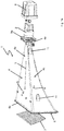
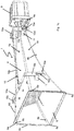
- FIG. 1 shows an embodiment of a sound system 1 according to the present invention, wherein the FIG. 1a an exploded view of the sound system 1 without mounting bracket, the Figure 1 b a mounting bracket 10 for engaging with the sound system 1 according to the FIG. 1a and the Figure 1c the sound system 1 from the FIG. 1a with the mounting bracket 10 off Figure 1 b demonstrate.
- the sounding device 1 has a horn 4 in the form of a funnel-shaped hollow body with a sound inlet opening 5 and a sound outlet opening 6.
- a first, planar side surface 4a extends up to the sound exit opening 6 opposite the sound inlet opening 5.
- a second side surface 4b concavely curved outwards from the sound inlet opening 5 to the sound outlet opening 6 connects the sound inlet opening 5 and the sound outlet opening 6th
- the cross section of the hollow body is rectangular throughout and widens from the sound inlet opening 5 to the sound outlet opening 6, wherein the sound inlet opening 5 has a circular opening cross-section, but which merges directly into a rectangular cross-section.
- the sound inlet opening 5 is a central, circular opening in a substantially flat flange plate 4e, which is flush with the end of the horn, which has a rectangular cross-section, or integrally connected thereto.
- the sound outlet opening 6 has a rectangular opening cross-section.
- the cross-sectional areas of sound inlet to sound outlet behave approximately as 1: 180, wherein the distance between sound inlet to sound outlet in about 20% to 60% greater than the width of the sound outlet, which in turn is about twice the height of this sound outlet.
- a sound generator 2 is arranged at or near the sound inlet opening 5, a sound generator 2 is arranged.
- the sound generator 2 has an opening, behind which a sound-generating membrane is arranged.
- the opening of the sounder 2 is arranged in alignment with the sound inlet opening 5, wherein the diameter of the opening of the sound generator 2 corresponds to the diameter of the sound inlet opening 5.
- the projected along the main radiation in a plane perpendicular to this plane surface of the membrane is in the sound inlet opening 5, or covers it. In general, then the symmetry axis of such, typically circular or rotationally symmetric membrane and the main emission direction coincide.
- the sounder 2 converts an electrical signal into an acoustic signal.
- the acoustic signal is passed through the sound inlet opening 5 in the horn 4. Since the sound generator 2 is arranged directly on the sound inlet opening 5, formed at the sound inlet opening 5 no significant reflections that could worsen the acoustic signal.
- the guided in the horn 4 acoustic signal propagates in the funnel-shaped hollow body.
- the sounder 2 is also arranged immediately adjacent to the flat side surface 4a or an imaginary extension of the same in such a way that its Schoabstrahlraum 3 parallel and low Distance from the flat side surface 4a of the sound inlet opening 5 to the sound outlet opening 6 extends.
- a housing 9 In order to protect the sounder 2 from external influences, this is arranged in a housing 9.
- the housing 9 is sealed with a seal 9a relative to the horn 4, so that the housing 9 is sealed watertight and dustproof.
- the sound exit opening 6 has a stiffening bead, i. a circumferential edge reinforcement 6c.
- the stiffening bead stiffens the sound outlet opening 6 and prevents it from being vibrated in a natural mode during operation.
- the inner corners 6a of the sound outlet opening 6 have a rounding 6b with a radius of a few millimeters.
- Grating 7 is arranged.
- the grille 7 is seated in a grating receptacle, for example in the form of flat grooves or protrusions, which are in the FIG. 1 are not shown, and is screwed with four retractable screws with the flat side surface 4a and the concave side surface 4b of the horn.
- the center distance between adjacent openings of the grating 7 is constant.
- the grating 7 is arranged at an angle of 65 ° to the flat side surface 4a and inclined in the direction of the sound inlet opening 5.
- the arranged on the flat side surface 4 a edge of the Grating 7 is located farther away from the sound entry opening 5 than the edge of the grating 7 arranged on the concave side surface 4b.
- the horn 4 has two holding devices 11 on its two opposite sides 4c and 4d.
- the holding devices 11 are wedge-shaped material reinforcements into which a screw or a threaded bolt with a nut can be screwed.
- Each two holding devices 11 are arranged in at the end of the horn 4 with the sound outlet opening 6 and the end of the horn 4 with the sound inlet opening 5.
- the provided for engaging with the holding devices 11 mounting bracket 10 is in the Figure 1 b shown.
- the mounting bracket 10 has two U-shaped bracket 10 a, which are aligned parallel to each other and are connected to each other via a web 10 b.
- Each bracket 10a has for the at least partially encompassing of the horn 4 two legs 10c with a slot 10d and an insertion 10e.
- the screwed into the holding device 11 screw is guided over the insertion 10e in the slot 10d.
- the position of the horn 4 relative to the mounting bracket 10 can be adjusted. Subsequently, the screws are tightened and connect the legs 10c firmly with the holding devices 11th
- FIG. 1c is the sound system 1 according to the FIG. 1a with a fixed mounting bracket 10 according to the Figure 1 b shown.
- the web 10b of the mounting bracket 10 extends in the direction of the sound inlet opening 5 to the sound outlet opening 6.
- the web 10b has a distance from the flat side surface 4a of the horn.
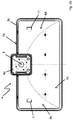
- FIG. 2 shows a horn 4 of another embodiment of a sound system 1 according to the present invention. That in the FIG. 2 shown horn 4 is for in the FIG. 1 Provided sounding device 1 shown, wherein in the FIG. 2a a side view, in the figure 2b is a plan view of the back of the sound inlet opening 5 and in the Figure 2c a plan view of the first, planar side surface 4a of the horn 4 are shown.
- first, planar side surface 4 a of the horn 4 extends from the sound inlet opening 5 to the sound outlet opening 6 and thus connects the sound inlet opening 5 with the sound outlet opening 6.
- a second, concave side surface 4b of the horn 4 is arranged.
- the second, concave side surface 4b connects the sound inlet opening 5 with the sound outlet opening 6 and forms together with the two other side surfaces 4c, 4d a funnel-shaped hollow body through which the acoustic signal is passed during operation of the sound system.
- the Indian FIG. 2 Sounder 2 is arranged close to or at the sound inlet opening 5 during operation of the sound reinforcement device.
- the sounder 2 is fixed to the flange 4e of the horn such that the sounder is disposed immediately adjacent to the flat side surface 4a or an imaginary extension of the flat side surface 4a and its Schoabstrahlraum parallel to the first, flat side surface 4a extends from the sound inlet opening 5 to the sound outlet opening 6.
- the flange 4e is also the attachment of a, in the FIG. 2 also not shown, housing 9, which protects the sounder 2 during operation of the sound system from environmental influences.
- each two holding devices 11 for engaging with a mounting bracket 10, which in the FIG. 2 not shown, arranged.
- the holding devices 11 are arranged such that in an operation of the sounding device, the web 10b of a mounting bracket 10 is arranged at a distance from the first, planar side surface 4a.
- the distance is selected so that the web 2 in a in the FIG. 2a shown side view at a height with the upper edge of the flange 4e completes.
- the horn 4 Surrounding the sound outlet opening 6, the horn 4 has an edge reinforcement 6c, which prevents the horn 4 is set in natural vibration in an operation of the sound system by the sound guided by the horn 4.
- the FIG. 2b shows the horn 4 in a plan view of the back of the sound inlet opening 5.
- the sound inlet opening 5 is a circular opening in the flange 4e.
- the diameter of the sound inlet opening 5 is preferably selected so that the diameter of a diaphragm of a sounder 2 corresponds, which is arranged in operation of the sound system at or near the sound inlet opening 5.
- the sound inlet opening 5 is arranged in the flange 4e such that the edge of the sound inlet opening 5 is located directly adjacent to the first, flat side surface 4a.
- FIGS. 2a and 2 B are in the Figure 2c showing a plan view of the first planar side surface 4a, the holding devices 11 mounted on each of the two side surfaces 4c, 4d for engaging with a mounting bracket 10 to recognize.
- the holding devices 11 are wedge-shaped material reinforcements of the side walls 4c, 4d.
Landscapes
- Physics & Mathematics (AREA)
- Engineering & Computer Science (AREA)
- Acoustics & Sound (AREA)
- Multimedia (AREA)
- Obtaining Desirable Characteristics In Audible-Bandwidth Transducers (AREA)
- Apparatuses For Generation Of Mechanical Vibrations (AREA)
- Transducers For Ultrasonic Waves (AREA)
- Circuit For Audible Band Transducer (AREA)
Priority Applications (1)
| Application Number | Priority Date | Filing Date | Title |
|---|---|---|---|
| PL17160914T PL3226237T3 (pl) | 2016-04-01 | 2017-03-14 | Urządzenie nagłaśniające |
Applications Claiming Priority (1)
| Application Number | Priority Date | Filing Date | Title |
|---|---|---|---|
| DE102016106045.3A DE102016106045A1 (de) | 2016-04-01 | 2016-04-01 | Beschallungseinrichtung |
Publications (3)
| Publication Number | Publication Date |
|---|---|
| EP3226237A2 true EP3226237A2 (fr) | 2017-10-04 |
| EP3226237A3 EP3226237A3 (fr) | 2017-12-27 |
| EP3226237B1 EP3226237B1 (fr) | 2021-01-13 |
Family
ID=58387630
Family Applications (1)
| Application Number | Title | Priority Date | Filing Date |
|---|---|---|---|
| EP17160914.2A Active EP3226237B1 (fr) | 2016-04-01 | 2017-03-14 | Dispositif de diffusion sonore |
Country Status (4)
| Country | Link |
|---|---|
| EP (1) | EP3226237B1 (fr) |
| DE (1) | DE102016106045A1 (fr) |
| ES (1) | ES2846865T3 (fr) |
| PL (1) | PL3226237T3 (fr) |
Family Cites Families (13)
| Publication number | Priority date | Publication date | Assignee | Title |
|---|---|---|---|---|
| US718073A (en) * | 1902-09-24 | 1903-01-13 | Walter Barnes | Support for horns for talking-machines. |
| US898520A (en) * | 1907-08-27 | 1908-09-15 | Samuel D Solomon | Megaphone-holder for phonograph-cabinets. |
| US1532811A (en) * | 1924-08-29 | 1925-04-07 | Graham Edward Alfred | Cabinet for use with sound-reproducing devices |
| US4171678A (en) * | 1977-07-22 | 1979-10-23 | Midland-Ross Corporation | Air horn |
| JPS5834863Y2 (ja) * | 1979-07-11 | 1983-08-05 | 松下電器産業株式会社 | ホ−ンスピ−カ |
| JPS5890794U (ja) * | 1981-12-15 | 1983-06-20 | 日本電音株式会社 | ストレ−トホ−ンスピ−カ |
| JPH02211798A (ja) * | 1989-02-10 | 1990-08-23 | J F B:Kk | 低音用ホーンスピーカ |
| JPH07322387A (ja) * | 1994-05-24 | 1995-12-08 | Sony Corp | 音響装置 |
| US6516741B1 (en) * | 2000-09-12 | 2003-02-11 | Hadley Products | Leak proof apparatus for mounting components to panels |
| NL1019961C2 (nl) * | 2002-02-14 | 2003-08-15 | Duran Audio B V | Akoestische weergever. |
| DE10338539A1 (de) * | 2003-08-19 | 2005-03-31 | Ebe Elektro-Bau-Elemente Gmbh | Signalgeber für Straßenbahnen und dgl. |
| NL2011074C2 (en) * | 2013-07-01 | 2015-01-05 | Duran Audio B V | Sound speaker grill arrangement and sound speaker comprising such grill arrangement. |
| CN203596900U (zh) * | 2013-11-26 | 2014-05-14 | 天津中环真美声学技术有限公司 | 扬声器用增益导向号筒 |
-
2016
- 2016-04-01 DE DE102016106045.3A patent/DE102016106045A1/de not_active Withdrawn
-
2017
- 2017-03-14 PL PL17160914T patent/PL3226237T3/pl unknown
- 2017-03-14 EP EP17160914.2A patent/EP3226237B1/fr active Active
- 2017-03-14 ES ES17160914T patent/ES2846865T3/es active Active
Non-Patent Citations (1)
| Title |
|---|
| None |
Also Published As
| Publication number | Publication date |
|---|---|
| PL3226237T3 (pl) | 2021-08-16 |
| ES2846865T3 (es) | 2021-07-29 |
| DE102016106045A1 (de) | 2017-10-05 |
| EP3226237B1 (fr) | 2021-01-13 |
| EP3226237A3 (fr) | 2017-12-27 |
Similar Documents
| Publication | Publication Date | Title |
|---|---|---|
| DE60115148T2 (de) | Lautsprecher für Decken mit direkter Verlegung | |
| DE102012107645B4 (de) | Akustischer wandler | |
| EP2734860B1 (fr) | Connexion de montage d'un véhicule automobile | |
| DE9311323U1 (de) | Schallabsorbierende Einrichtung für eine Schallisolationswand | |
| DE102011105046A1 (de) | Ultraschallsensorvorrichtung für ein Fahrzeug sowie Anordnung mit einer derartigen Ultraschallsensorvorrichtung | |
| EP1258848A2 (fr) | Détecteur optique de fumée | |
| EP3226237A2 (fr) | Dispositif de diffusion sonore | |
| CH707518B1 (de) | Metallzarge. | |
| DE19650522C2 (de) | Kegelförmiger Lautsprechervorsatz | |
| DE3529402C1 (de) | Verfahren zum Überwachen des Zustandes von Räumen | |
| DE3420439A1 (de) | Gehaeuse fuer ueberwachungsanlagen | |
| DE29804203U1 (de) | Schutzabdeckung für brandgefährdete elektrische Installationen | |
| DE102013015352B4 (de) | Blendenprofil zur Anbringung einer Abschlussblende an einem Ojekt, zum Beispiel einem Möbelstück und System, umfassend ein Blendenprofil, ein Objekt und eine Abschlussblende | |
| DE20112669U1 (de) | Schallabsorbierendes Paneel | |
| DE2226306B2 (de) | Ultraschall-Sende- und Empfangsgerät für Freiluftbetrieb | |
| EP2768238B1 (fr) | Haut-parleur de plafond avec un cache | |
| DE202015007639U1 (de) | Montagevorrichtung zur Befestigung mindestens eines Objekts an einer tragenden Vorrichtung | |
| DE202015005705U1 (de) | Lautsprecheranordnung | |
| DE102010008409B4 (de) | Einbauteil zur Aufnahme und/oder Befestigung eines Tellerventils, Lüftungsgitters oder ähnlichen lufttechnischen Ausrüstungsmitteln | |
| AT10910U1 (de) | Akustikpaneel | |
| EP2778317A2 (fr) | Dispositif de fixation d'un élément de façade à un mur | |
| EP1630311A2 (fr) | Dispositif d'absorption acoustique, en particulier pour le montage sur un plafond ou mur | |
| DE9313346U1 (de) | Abdeckung für Lautsprecher | |
| DE102013226916A1 (de) | Akustische Signalvorrichtung | |
| DE2333931A1 (de) | Verfahren und anlage zum erzeugen eines alarmsignales bei bruch eines doppelglasfensters |
Legal Events
| Date | Code | Title | Description |
|---|---|---|---|
| PUAI | Public reference made under article 153(3) epc to a published international application that has entered the european phase |
Free format text: ORIGINAL CODE: 0009012 |
|
| STAA | Information on the status of an ep patent application or granted ep patent |
Free format text: STATUS: THE APPLICATION HAS BEEN PUBLISHED |
|
| AK | Designated contracting states |
Kind code of ref document: A2 Designated state(s): AL AT BE BG CH CY CZ DE DK EE ES FI FR GB GR HR HU IE IS IT LI LT LU LV MC MK MT NL NO PL PT RO RS SE SI SK SM TR |
|
| AX | Request for extension of the european patent |
Extension state: BA ME |
|
| PUAL | Search report despatched |
Free format text: ORIGINAL CODE: 0009013 |
|
| AK | Designated contracting states |
Kind code of ref document: A3 Designated state(s): AL AT BE BG CH CY CZ DE DK EE ES FI FR GB GR HR HU IE IS IT LI LT LU LV MC MK MT NL NO PL PT RO RS SE SI SK SM TR |
|
| AX | Request for extension of the european patent |
Extension state: BA ME |
|
| RIC1 | Information provided on ipc code assigned before grant |
Ipc: G10K 13/00 20060101ALI20171117BHEP Ipc: G10K 11/02 20060101AFI20171117BHEP |
|
| STAA | Information on the status of an ep patent application or granted ep patent |
Free format text: STATUS: REQUEST FOR EXAMINATION WAS MADE |
|
| 17P | Request for examination filed |
Effective date: 20180416 |
|
| RBV | Designated contracting states (corrected) |
Designated state(s): AL AT BE BG CH CY CZ DE DK EE ES FI FR GB GR HR HU IE IS IT LI LT LU LV MC MK MT NL NO PL PT RO RS SE SI SK SM TR |
|
| STAA | Information on the status of an ep patent application or granted ep patent |
Free format text: STATUS: EXAMINATION IS IN PROGRESS |
|
| 17Q | First examination report despatched |
Effective date: 20190524 |
|
| GRAP | Despatch of communication of intention to grant a patent |
Free format text: ORIGINAL CODE: EPIDOSNIGR1 |
|
| STAA | Information on the status of an ep patent application or granted ep patent |
Free format text: STATUS: GRANT OF PATENT IS INTENDED |
|
| INTG | Intention to grant announced |
Effective date: 20201106 |
|
| GRAS | Grant fee paid |
Free format text: ORIGINAL CODE: EPIDOSNIGR3 |
|
| GRAA | (expected) grant |
Free format text: ORIGINAL CODE: 0009210 |
|
| STAA | Information on the status of an ep patent application or granted ep patent |
Free format text: STATUS: THE PATENT HAS BEEN GRANTED |
|
| AK | Designated contracting states |
Kind code of ref document: B1 Designated state(s): AL AT BE BG CH CY CZ DE DK EE ES FI FR GB GR HR HU IE IS IT LI LT LU LV MC MK MT NL NO PL PT RO RS SE SI SK SM TR |
|
| REG | Reference to a national code |
Ref country code: GB Ref legal event code: FG4D Free format text: NOT ENGLISH |
|
| REG | Reference to a national code |
Ref country code: CH Ref legal event code: EP |
|
| REG | Reference to a national code |
Ref country code: DE Ref legal event code: R096 Ref document number: 502017009026 Country of ref document: DE |
|
| REG | Reference to a national code |
Ref country code: IE Ref legal event code: FG4D Free format text: LANGUAGE OF EP DOCUMENT: GERMAN |
|
| REG | Reference to a national code |
Ref country code: AT Ref legal event code: REF Ref document number: 1355137 Country of ref document: AT Kind code of ref document: T Effective date: 20210215 |
|
| REG | Reference to a national code |
Ref country code: CH Ref legal event code: NV Representative=s name: ISLER AND PEDRAZZINI AG, CH |
|
| REG | Reference to a national code |
Ref country code: NL Ref legal event code: FP |
|
| REG | Reference to a national code |
Ref country code: LT Ref legal event code: MG9D |
|
| REG | Reference to a national code |
Ref country code: ES Ref legal event code: FG2A Ref document number: 2846865 Country of ref document: ES Kind code of ref document: T3 Effective date: 20210729 |
|
| PG25 | Lapsed in a contracting state [announced via postgrant information from national office to epo] |
Ref country code: HR Free format text: LAPSE BECAUSE OF FAILURE TO SUBMIT A TRANSLATION OF THE DESCRIPTION OR TO PAY THE FEE WITHIN THE PRESCRIBED TIME-LIMIT Effective date: 20210113 Ref country code: GR Free format text: LAPSE BECAUSE OF FAILURE TO SUBMIT A TRANSLATION OF THE DESCRIPTION OR TO PAY THE FEE WITHIN THE PRESCRIBED TIME-LIMIT Effective date: 20210414 Ref country code: FI Free format text: LAPSE BECAUSE OF FAILURE TO SUBMIT A TRANSLATION OF THE DESCRIPTION OR TO PAY THE FEE WITHIN THE PRESCRIBED TIME-LIMIT Effective date: 20210113 Ref country code: NO Free format text: LAPSE BECAUSE OF FAILURE TO SUBMIT A TRANSLATION OF THE DESCRIPTION OR TO PAY THE FEE WITHIN THE PRESCRIBED TIME-LIMIT Effective date: 20210413 Ref country code: PT Free format text: LAPSE BECAUSE OF FAILURE TO SUBMIT A TRANSLATION OF THE DESCRIPTION OR TO PAY THE FEE WITHIN THE PRESCRIBED TIME-LIMIT Effective date: 20210513 Ref country code: BG Free format text: LAPSE BECAUSE OF FAILURE TO SUBMIT A TRANSLATION OF THE DESCRIPTION OR TO PAY THE FEE WITHIN THE PRESCRIBED TIME-LIMIT Effective date: 20210413 Ref country code: LT Free format text: LAPSE BECAUSE OF FAILURE TO SUBMIT A TRANSLATION OF THE DESCRIPTION OR TO PAY THE FEE WITHIN THE PRESCRIBED TIME-LIMIT Effective date: 20210113 |
|
| PG25 | Lapsed in a contracting state [announced via postgrant information from national office to epo] |
Ref country code: SE Free format text: LAPSE BECAUSE OF FAILURE TO SUBMIT A TRANSLATION OF THE DESCRIPTION OR TO PAY THE FEE WITHIN THE PRESCRIBED TIME-LIMIT Effective date: 20210113 Ref country code: RS Free format text: LAPSE BECAUSE OF FAILURE TO SUBMIT A TRANSLATION OF THE DESCRIPTION OR TO PAY THE FEE WITHIN THE PRESCRIBED TIME-LIMIT Effective date: 20210113 Ref country code: LV Free format text: LAPSE BECAUSE OF FAILURE TO SUBMIT A TRANSLATION OF THE DESCRIPTION OR TO PAY THE FEE WITHIN THE PRESCRIBED TIME-LIMIT Effective date: 20210113 |
|
| PG25 | Lapsed in a contracting state [announced via postgrant information from national office to epo] |
Ref country code: IS Free format text: LAPSE BECAUSE OF FAILURE TO SUBMIT A TRANSLATION OF THE DESCRIPTION OR TO PAY THE FEE WITHIN THE PRESCRIBED TIME-LIMIT Effective date: 20210513 |
|
| REG | Reference to a national code |
Ref country code: DE Ref legal event code: R097 Ref document number: 502017009026 Country of ref document: DE |
|
| PG25 | Lapsed in a contracting state [announced via postgrant information from national office to epo] |
Ref country code: MC Free format text: LAPSE BECAUSE OF FAILURE TO SUBMIT A TRANSLATION OF THE DESCRIPTION OR TO PAY THE FEE WITHIN THE PRESCRIBED TIME-LIMIT Effective date: 20210113 Ref country code: CZ Free format text: LAPSE BECAUSE OF FAILURE TO SUBMIT A TRANSLATION OF THE DESCRIPTION OR TO PAY THE FEE WITHIN THE PRESCRIBED TIME-LIMIT Effective date: 20210113 Ref country code: EE Free format text: LAPSE BECAUSE OF FAILURE TO SUBMIT A TRANSLATION OF THE DESCRIPTION OR TO PAY THE FEE WITHIN THE PRESCRIBED TIME-LIMIT Effective date: 20210113 Ref country code: SM Free format text: LAPSE BECAUSE OF FAILURE TO SUBMIT A TRANSLATION OF THE DESCRIPTION OR TO PAY THE FEE WITHIN THE PRESCRIBED TIME-LIMIT Effective date: 20210113 |
|
| PLBE | No opposition filed within time limit |
Free format text: ORIGINAL CODE: 0009261 |
|
| STAA | Information on the status of an ep patent application or granted ep patent |
Free format text: STATUS: NO OPPOSITION FILED WITHIN TIME LIMIT |
|
| PG25 | Lapsed in a contracting state [announced via postgrant information from national office to epo] |
Ref country code: DK Free format text: LAPSE BECAUSE OF FAILURE TO SUBMIT A TRANSLATION OF THE DESCRIPTION OR TO PAY THE FEE WITHIN THE PRESCRIBED TIME-LIMIT Effective date: 20210113 Ref country code: SK Free format text: LAPSE BECAUSE OF FAILURE TO SUBMIT A TRANSLATION OF THE DESCRIPTION OR TO PAY THE FEE WITHIN THE PRESCRIBED TIME-LIMIT Effective date: 20210113 Ref country code: RO Free format text: LAPSE BECAUSE OF FAILURE TO SUBMIT A TRANSLATION OF THE DESCRIPTION OR TO PAY THE FEE WITHIN THE PRESCRIBED TIME-LIMIT Effective date: 20210113 |
|
| 26N | No opposition filed |
Effective date: 20211014 |
|
| PG25 | Lapsed in a contracting state [announced via postgrant information from national office to epo] |
Ref country code: LU Free format text: LAPSE BECAUSE OF NON-PAYMENT OF DUE FEES Effective date: 20210314 Ref country code: AL Free format text: LAPSE BECAUSE OF FAILURE TO SUBMIT A TRANSLATION OF THE DESCRIPTION OR TO PAY THE FEE WITHIN THE PRESCRIBED TIME-LIMIT Effective date: 20210113 Ref country code: IE Free format text: LAPSE BECAUSE OF NON-PAYMENT OF DUE FEES Effective date: 20210314 |
|
| PG25 | Lapsed in a contracting state [announced via postgrant information from national office to epo] |
Ref country code: SI Free format text: LAPSE BECAUSE OF FAILURE TO SUBMIT A TRANSLATION OF THE DESCRIPTION OR TO PAY THE FEE WITHIN THE PRESCRIBED TIME-LIMIT Effective date: 20210113 |
|
| PG25 | Lapsed in a contracting state [announced via postgrant information from national office to epo] |
Ref country code: IS Free format text: LAPSE BECAUSE OF FAILURE TO SUBMIT A TRANSLATION OF THE DESCRIPTION OR TO PAY THE FEE WITHIN THE PRESCRIBED TIME-LIMIT Effective date: 20210513 |
|
| PG25 | Lapsed in a contracting state [announced via postgrant information from national office to epo] |
Ref country code: HU Free format text: LAPSE BECAUSE OF FAILURE TO SUBMIT A TRANSLATION OF THE DESCRIPTION OR TO PAY THE FEE WITHIN THE PRESCRIBED TIME-LIMIT; INVALID AB INITIO Effective date: 20170314 |
|
| PG25 | Lapsed in a contracting state [announced via postgrant information from national office to epo] |
Ref country code: CY Free format text: LAPSE BECAUSE OF FAILURE TO SUBMIT A TRANSLATION OF THE DESCRIPTION OR TO PAY THE FEE WITHIN THE PRESCRIBED TIME-LIMIT Effective date: 20210113 |
|
| PG25 | Lapsed in a contracting state [announced via postgrant information from national office to epo] |
Ref country code: MK Free format text: LAPSE BECAUSE OF FAILURE TO SUBMIT A TRANSLATION OF THE DESCRIPTION OR TO PAY THE FEE WITHIN THE PRESCRIBED TIME-LIMIT Effective date: 20210113 |
|
| PG25 | Lapsed in a contracting state [announced via postgrant information from national office to epo] |
Ref country code: MT Free format text: LAPSE BECAUSE OF FAILURE TO SUBMIT A TRANSLATION OF THE DESCRIPTION OR TO PAY THE FEE WITHIN THE PRESCRIBED TIME-LIMIT Effective date: 20210113 |
|
| PGFP | Annual fee paid to national office [announced via postgrant information from national office to epo] |
Ref country code: DE Payment date: 20250318 Year of fee payment: 9 |
|
| PGFP | Annual fee paid to national office [announced via postgrant information from national office to epo] |
Ref country code: NL Payment date: 20250319 Year of fee payment: 9 |
|
| PGFP | Annual fee paid to national office [announced via postgrant information from national office to epo] |
Ref country code: AT Payment date: 20250320 Year of fee payment: 9 Ref country code: BE Payment date: 20250319 Year of fee payment: 9 |
|
| PGFP | Annual fee paid to national office [announced via postgrant information from national office to epo] |
Ref country code: FR Payment date: 20250325 Year of fee payment: 9 Ref country code: PL Payment date: 20250219 Year of fee payment: 9 |
|
| PGFP | Annual fee paid to national office [announced via postgrant information from national office to epo] |
Ref country code: IT Payment date: 20250325 Year of fee payment: 9 Ref country code: GB Payment date: 20250321 Year of fee payment: 9 |
|
| PGFP | Annual fee paid to national office [announced via postgrant information from national office to epo] |
Ref country code: ES Payment date: 20250429 Year of fee payment: 9 |
|
| PGFP | Annual fee paid to national office [announced via postgrant information from national office to epo] |
Ref country code: CH Payment date: 20250401 Year of fee payment: 9 |
|
| PG25 | Lapsed in a contracting state [announced via postgrant information from national office to epo] |
Ref country code: TR Free format text: LAPSE BECAUSE OF FAILURE TO SUBMIT A TRANSLATION OF THE DESCRIPTION OR TO PAY THE FEE WITHIN THE PRESCRIBED TIME-LIMIT Effective date: 20210113 |