EP3225859B1 - Verriegelungsvorrichtung für hängende leitung - Google Patents
Verriegelungsvorrichtung für hängende leitung Download PDFInfo
- Publication number
- EP3225859B1 EP3225859B1 EP17164148.3A EP17164148A EP3225859B1 EP 3225859 B1 EP3225859 B1 EP 3225859B1 EP 17164148 A EP17164148 A EP 17164148A EP 3225859 B1 EP3225859 B1 EP 3225859B1
- Authority
- EP
- European Patent Office
- Prior art keywords
- locking device
- casing
- locking element
- rod
- threading
- Prior art date
- Legal status (The legal status is an assumption and is not a legal conclusion. Google has not performed a legal analysis and makes no representation as to the accuracy of the status listed.)
- Not-in-force
Links
- 238000003780 insertion Methods 0.000 claims description 11
- 230000037431 insertion Effects 0.000 claims description 11
- 230000008878 coupling Effects 0.000 claims description 9
- 238000010168 coupling process Methods 0.000 claims description 9
- 238000005859 coupling reaction Methods 0.000 claims description 9
- 230000000295 complement effect Effects 0.000 claims description 6
- 230000009471 action Effects 0.000 claims description 4
- 239000007787 solid Substances 0.000 claims 1
- 238000009434 installation Methods 0.000 description 11
- 230000007246 mechanism Effects 0.000 description 5
- 230000007613 environmental effect Effects 0.000 description 3
- 239000000428 dust Substances 0.000 description 2
- 238000005304 joining Methods 0.000 description 2
- 238000004519 manufacturing process Methods 0.000 description 2
- 239000002184 metal Substances 0.000 description 2
- 239000002245 particle Substances 0.000 description 2
- 238000004378 air conditioning Methods 0.000 description 1
- 230000000712 assembly Effects 0.000 description 1
- 238000000429 assembly Methods 0.000 description 1
- 230000006835 compression Effects 0.000 description 1
- 238000007906 compression Methods 0.000 description 1
- 238000009429 electrical wiring Methods 0.000 description 1
- 230000005611 electricity Effects 0.000 description 1
- 238000011900 installation process Methods 0.000 description 1
- 238000002955 isolation Methods 0.000 description 1
- 238000012423 maintenance Methods 0.000 description 1
- 238000000034 method Methods 0.000 description 1
- 230000003647 oxidation Effects 0.000 description 1
- 238000007254 oxidation reaction Methods 0.000 description 1
- 238000009428 plumbing Methods 0.000 description 1
- 238000003825 pressing Methods 0.000 description 1
- 230000008569 process Effects 0.000 description 1
- 230000008439 repair process Effects 0.000 description 1
- 230000000284 resting effect Effects 0.000 description 1
Images



Classifications
-
- F—MECHANICAL ENGINEERING; LIGHTING; HEATING; WEAPONS; BLASTING
- F16—ENGINEERING ELEMENTS AND UNITS; GENERAL MEASURES FOR PRODUCING AND MAINTAINING EFFECTIVE FUNCTIONING OF MACHINES OR INSTALLATIONS; THERMAL INSULATION IN GENERAL
- F16L—PIPES; JOINTS OR FITTINGS FOR PIPES; SUPPORTS FOR PIPES, CABLES OR PROTECTIVE TUBING; MEANS FOR THERMAL INSULATION IN GENERAL
- F16L3/00—Supports for pipes, cables or protective tubing, e.g. hangers, holders, clamps, cleats, clips, brackets
- F16L3/26—Supports for pipes, cables or protective tubing, e.g. hangers, holders, clamps, cleats, clips, brackets specially adapted for supporting the pipes all along their length, e.g. pipe channels or ducts
-
- F—MECHANICAL ENGINEERING; LIGHTING; HEATING; WEAPONS; BLASTING
- F16—ENGINEERING ELEMENTS AND UNITS; GENERAL MEASURES FOR PRODUCING AND MAINTAINING EFFECTIVE FUNCTIONING OF MACHINES OR INSTALLATIONS; THERMAL INSULATION IN GENERAL
- F16B—DEVICES FOR FASTENING OR SECURING CONSTRUCTIONAL ELEMENTS OR MACHINE PARTS TOGETHER, e.g. NAILS, BOLTS, CIRCLIPS, CLAMPS, CLIPS OR WEDGES; JOINTS OR JOINTING
- F16B37/00—Nuts or like thread-engaging members
- F16B37/08—Quickly-detachable or mountable nuts, e.g. consisting of two or more parts; Nuts movable along the bolt after tilting the nut
-
- F—MECHANICAL ENGINEERING; LIGHTING; HEATING; WEAPONS; BLASTING
- F16—ENGINEERING ELEMENTS AND UNITS; GENERAL MEASURES FOR PRODUCING AND MAINTAINING EFFECTIVE FUNCTIONING OF MACHINES OR INSTALLATIONS; THERMAL INSULATION IN GENERAL
- F16B—DEVICES FOR FASTENING OR SECURING CONSTRUCTIONAL ELEMENTS OR MACHINE PARTS TOGETHER, e.g. NAILS, BOLTS, CIRCLIPS, CLAMPS, CLIPS OR WEDGES; JOINTS OR JOINTING
- F16B37/00—Nuts or like thread-engaging members
- F16B37/08—Quickly-detachable or mountable nuts, e.g. consisting of two or more parts; Nuts movable along the bolt after tilting the nut
- F16B37/0807—Nuts engaged from the end of the bolt, e.g. axially slidable nuts
- F16B37/0857—Nuts engaged from the end of the bolt, e.g. axially slidable nuts with the threaded portions of the nut engaging the thread of the bolt by the action of one or more springs or resilient retaining members
-
- F—MECHANICAL ENGINEERING; LIGHTING; HEATING; WEAPONS; BLASTING
- F16—ENGINEERING ELEMENTS AND UNITS; GENERAL MEASURES FOR PRODUCING AND MAINTAINING EFFECTIVE FUNCTIONING OF MACHINES OR INSTALLATIONS; THERMAL INSULATION IN GENERAL
- F16B—DEVICES FOR FASTENING OR SECURING CONSTRUCTIONAL ELEMENTS OR MACHINE PARTS TOGETHER, e.g. NAILS, BOLTS, CIRCLIPS, CLAMPS, CLIPS OR WEDGES; JOINTS OR JOINTING
- F16B37/00—Nuts or like thread-engaging members
- F16B37/08—Quickly-detachable or mountable nuts, e.g. consisting of two or more parts; Nuts movable along the bolt after tilting the nut
- F16B37/0807—Nuts engaged from the end of the bolt, e.g. axially slidable nuts
- F16B37/0864—Nuts engaged from the end of the bolt, e.g. axially slidable nuts with the threaded portions of the nut engaging the thread of the bolt by pressing or rotating an external retaining member such as a cap, a nut, a ring or a sleeve
-
- F—MECHANICAL ENGINEERING; LIGHTING; HEATING; WEAPONS; BLASTING
- F16—ENGINEERING ELEMENTS AND UNITS; GENERAL MEASURES FOR PRODUCING AND MAINTAINING EFFECTIVE FUNCTIONING OF MACHINES OR INSTALLATIONS; THERMAL INSULATION IN GENERAL
- F16L—PIPES; JOINTS OR FITTINGS FOR PIPES; SUPPORTS FOR PIPES, CABLES OR PROTECTIVE TUBING; MEANS FOR THERMAL INSULATION IN GENERAL
- F16L3/00—Supports for pipes, cables or protective tubing, e.g. hangers, holders, clamps, cleats, clips, brackets
- F16L3/08—Supports for pipes, cables or protective tubing, e.g. hangers, holders, clamps, cleats, clips, brackets substantially surrounding the pipe, cable or protective tubing
- F16L3/12—Supports for pipes, cables or protective tubing, e.g. hangers, holders, clamps, cleats, clips, brackets substantially surrounding the pipe, cable or protective tubing comprising a member substantially surrounding the pipe, cable or protective tubing
- F16L3/137—Supports for pipes, cables or protective tubing, e.g. hangers, holders, clamps, cleats, clips, brackets substantially surrounding the pipe, cable or protective tubing comprising a member substantially surrounding the pipe, cable or protective tubing and consisting of a flexible band
-
- F—MECHANICAL ENGINEERING; LIGHTING; HEATING; WEAPONS; BLASTING
- F16—ENGINEERING ELEMENTS AND UNITS; GENERAL MEASURES FOR PRODUCING AND MAINTAINING EFFECTIVE FUNCTIONING OF MACHINES OR INSTALLATIONS; THERMAL INSULATION IN GENERAL
- F16L—PIPES; JOINTS OR FITTINGS FOR PIPES; SUPPORTS FOR PIPES, CABLES OR PROTECTIVE TUBING; MEANS FOR THERMAL INSULATION IN GENERAL
- F16L3/00—Supports for pipes, cables or protective tubing, e.g. hangers, holders, clamps, cleats, clips, brackets
- F16L3/22—Supports for pipes, cables or protective tubing, e.g. hangers, holders, clamps, cleats, clips, brackets specially adapted for supporting a number of parallel pipes at intervals
- F16L3/23—Supports for pipes, cables or protective tubing, e.g. hangers, holders, clamps, cleats, clips, brackets specially adapted for supporting a number of parallel pipes at intervals for a bundle of pipes or a plurality of pipes placed side by side in contact with each other
- F16L3/233—Supports for pipes, cables or protective tubing, e.g. hangers, holders, clamps, cleats, clips, brackets specially adapted for supporting a number of parallel pipes at intervals for a bundle of pipes or a plurality of pipes placed side by side in contact with each other by means of a flexible band
-
- F—MECHANICAL ENGINEERING; LIGHTING; HEATING; WEAPONS; BLASTING
- F16—ENGINEERING ELEMENTS AND UNITS; GENERAL MEASURES FOR PRODUCING AND MAINTAINING EFFECTIVE FUNCTIONING OF MACHINES OR INSTALLATIONS; THERMAL INSULATION IN GENERAL
- F16L—PIPES; JOINTS OR FITTINGS FOR PIPES; SUPPORTS FOR PIPES, CABLES OR PROTECTIVE TUBING; MEANS FOR THERMAL INSULATION IN GENERAL
- F16L57/00—Protection of pipes or objects of similar shape against external or internal damage or wear
-
- F—MECHANICAL ENGINEERING; LIGHTING; HEATING; WEAPONS; BLASTING
- F24—HEATING; RANGES; VENTILATING
- F24F—AIR-CONDITIONING; AIR-HUMIDIFICATION; VENTILATION; USE OF AIR CURRENTS FOR SCREENING
- F24F1/00—Room units for air-conditioning, e.g. separate or self-contained units or units receiving primary air from a central station
- F24F1/06—Separate outdoor units, e.g. outdoor unit to be linked to a separate room comprising a compressor and a heat exchanger
- F24F1/26—Refrigerant piping
- F24F1/34—Protection means thereof, e.g. covers for refrigerant pipes
-
- H—ELECTRICITY
- H02—GENERATION; CONVERSION OR DISTRIBUTION OF ELECTRIC POWER
- H02G—INSTALLATION OF ELECTRIC CABLES OR LINES, OR OF COMBINED OPTICAL AND ELECTRIC CABLES OR LINES
- H02G3/00—Installations of electric cables or lines or protective tubing therefor in or on buildings, equivalent structures or vehicles
- H02G3/30—Installations of cables or lines on walls, floors or ceilings
- H02G3/32—Installations of cables or lines on walls, floors or ceilings using mounting clamps
Definitions
- the present invention belongs to the field of devices for joining or locking constructive elements, and more specifically, fastening and locking mechanisms of supports for telecommunications ducts, air conditioning tubes, electrical wiring, etc. that must be suspended at a certain height when installed.
- the object of the present invention is a locking device which, in addition to ensuring a secure and stable fastening of supports for suspended ducts with respect to threaded rods, without gaps or unwanted movements of the supports, also provides a quick and convenient installation and uninstallation thereof by the installer.
- these supports are fastened in a suspended way from ceilings through the use of small accessories, intended to support, hold, house and/or maintain the ducts in a secure and stable position.
- the supports basically consist of metal plates, upon which the duct is directly supported, equipped with at least one through hole, nuts with inner threading and locknuts into which a threaded rod, generally anchored or fastened to the ceiling or an upper beam, is inserted.
- the present invention provides a locking device that, in addition to ensuring a secure fastening of the supports with respect to a threaded rod, understanding the supports as accessories such as beams, brackets, cross-pieces, profiles, guides, plates and similar, intended to fasten and support pipelines, channels, gutters and trays or even the latter without the intervention of the cited accessory, in any of the cases mentioned in order to support and maintain in a stable position the suspended ducts, tubes or cables, hereinafter simply called "ducts", it is an easy-to-use solution for convenient, secure, versatile and quick installation/uninstallation by the installation personnel.
- the locking device herein described provides protection and additional safety to its components against external environmental conditions such as humidity, dust particles, etc.
- the locking device for duct supports object of the invention, comprises a casing that has side walls, an upper wall, and at least one hole into which a threaded rod can be inserted; a pair of pins located inside the casing, preferably at an angle inclined with respect to the vertical axial axis of the casing; a first spring likewise housed inside the casing; and a pair of primary bodies mounted on the first spring, wherein said primary bodies are pushed by the first spring against the upper inner wall of the casing, and are arranged facing each other in an upper inner area of the casing.
- These primary bodies have inner threading, complementary to the threading of the rod, and a through hole, preferably inclined, into which an upper end of the pins is inserted, the primary bodies being movable on the pins, particularly in the direction of the latter.
- the primary bodies are placed by the action of the first spring, in the upper portion of the pins, next to each other and both forming a single body.
- said primary bodies separate from each other, moving towards the lower portion of the pins, sliding along it so that later, once the rod is released, that is, once it stops applying pressure or acting upon the same, said primary bodies return to their initial upper position, then locking the rod by means of the inner threading of said primary bodies with respect to the threads of the rod.
- the locking device of the invention further comprises a first auxiliary locking element joined to the casing corresponding to the inlet hole, being equally equipped with a through hole for inserting a rod; and a second auxiliary locking element that is able to be coupled to the first auxiliary locking element.
- auxiliary locking elements make it possible to provide two additional locks, for the support as well as for the rod; therefore, there are three simultaneous locks obtained by means of the device of the invention.
- the primary bodies provide a first lock for the threaded rod, the components thereof being entirely protected and encapsulated within the casing.
- the second auxiliary locking element also makes it possible to equip the first locking element and the secondary bodies with protection and isolation against external environmental conditions, such that the respective threads remain intact and protected from the outside.
- the locking device described herein can also be included in or coupled to an accessory of those mentioned above (beams, brackets, cross-pieces, etc.). which support pipelines to house ducts, this application being particularly useful in those cases where the rods are anchored to the ceiling, such that by simply unscrewing the second locking element, the device of the invention can be inserted into the rod at the desired height, thus making a fine adjustment, or not, and once again threading said second locking element to definitely lock the entire assembly.
- the locking device of the invention by means of the locking device of the invention, the passage of threaded rods in one direction is permitted, locking them in the opposite direction with respect to the support. Furthermore, the locking device described herein has independent mobility with respect to the support, which allows the installer personnel to make a fine and precise adjustment thereof, without risk, and with the capacity to lock and stop the rotation of the supports in the place that requires the installation, as well as locking the entire assembly formed by the support, rod and locking device object of the invention. Therefore, a convenient, quick and effective solution is provided that allows the installer to carry out coupling/decoupling actions and adjustment of the suspended duct supports with respect to the threaded rods, considerably reducing installation times, with greater maneuverability and safety, and thus helping prevent work-related accidents when performing these tasks.
- a first embodiment of the locking device (1) of the invention can be seen, which comprises:
- the locking device comprises a base lid (13), shown in Figure 1 , coupled inferiorly to the casing (10), and has a central hole (13a) for the passage of the rod (B) and a pair of side knockout holes (13b) inclined for the insertion of a lower end of the pins (20).
- This feature makes it possible to further strengthen and secure, if possible, the correct positioning of the pins (20), providing double securing thereof, superiorly by means of through holes (42) of the primary bodies (40), and inferiorly by means of said side knockout holes (13b).
- the through holes (42) of the primary bodies (40) are inclined holes, which facilitates the angled arrangement of the pins (20) inside the casing (10), ensuring an optimal coupling and positioning thereof.
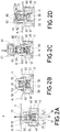
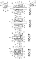
- Figures 2A-2H show cross-sectional views wherein the installation process of the locking device (1) of Figure 1 in a support (A) is shown, in this case it is shown as a simple horizontal metal plate but referred to as both a surface of a conventional support, such as a beam, bracket, cross-piece, profile, guide or similar suitable for supporting pipelines such as channels, gutters or trays that house ducts, and a surface of any of the mentioned pipelines without the use of said conventional support, provided with a hole; and the subsequent fastening of said support (A) and a threaded rod (B) inserted into the casing (10).
- a conventional support such as a beam, bracket, cross-piece, profile, guide or similar suitable for supporting pipelines such as channels, gutters or trays that house ducts, and a surface of any of the mentioned pipelines without the use of said conventional support, provided with a hole
- the locking device (1) is observed moving closer to the support (A) inferiorly according to the arrow shown, in order to insert the first auxiliary locking element (50) into the support (A) or vice versa, wherein, in this case, said first auxiliary locking element (50) and casing (10) make up the same body, thus reducing the number of independent pieces to handle, facilitating their installation and reducing manufacturing costs.
- the second auxiliary locking device (60) is coupled to the first auxiliary locking device (50).
- the first auxiliary locking device (50) has outer threading (52), while the second auxiliary locking device (60) has inner threading (61), such that the coupling and closure between both locking elements (50, 60) is obtained by the action and integral joining of their respective threading (52, 61) by simply rotating said second auxiliary locking element (60) according to the arrow shown in Figure 2D .
- the first spring (30) As for the first spring (30), it is in a stable position by means of partial upper and lower insertion into protrusions provided both in the lower portion of the primary bodies (40) and in the base lid (13) around the central hole (13a) mentioned above, as shown in Figures 1 , 2A-2H . Therefore, said first spring (30) is in a fixed position.
- the first spring (30) begins to act and due to its own tensile movement, as shown in Figure 2G , said first spring (30) exerts a vertical pushing force on the primary bodies (40), thus moving them towards their initial position through their respective pins (20) until their inner threading (41) comes in contact with the threading of the rod (B).
- the upper end of the first auxiliary locking element (50) is beveled, equipped with an inclined inner surface (51).
- the secondary bodies (80) have a conical, semicircular shape, equipped, in turn, with an inclined outer surface (82) intended to integrally come in contact with the inclined inner surface (51) of the first auxiliary locking element (50).
- the coupling and closure of the second auxiliary locking element (60) with respect to the first auxiliary locking element (50) causes the downward pushing and sliding of the secondary bodies (80), so that they move closer to each other until their inner threading (81) comes in contact with the threading of the rod (B), locking and preventing the latter from moving forward.
- the secondary bodies (80) can have a "U"-shaped transversal inlet (83), shown in Figure 1 , arranged on its upper face and which start from its inner threading (81) to its outer side walls. Furthermore, the possibility that the second auxiliary locking element (60) has a pair of upper stops (62), which project horizontally towards the center of said second locking element (60) without coming in contact with each other, leaving enough distance between said upper stops (62) in order to allow a threaded rod (B) to be inserted, is envisaged.
- the coupling of the second auxiliary locking element (60) to the first auxiliary locking element (50) causes contact and pushes said upper stops (62) on the transversal inlets (83) of the secondary bodies (80), thus helping the pushing and sliding of said locking elements (80) on the inclined inner surface (51) of the first auxiliary locking element (50).
- this second example foregoes the second spring (70), the secondary locking bodies (80), as well as the lid (13), the casing (10) forming a single closed body, equipped in this case with upper and lower holes, similar to those shown in Figure 2A in order to allow a rod (B) to be inserted.
- the first spring (30) rests on protrusions provided only in the lower base of the casing (10), as shown in figures 5A and 5B .
- the first flexible tabs (53) have an "L"-shaped distal end (53L) that converges towards the side wall of the cylindrical tube (50).
- the coupling and closure of the nut (60) on the cylindrical tube (50) causes pushing inside said flexible first tabs (53), making its "L"-shaped distal end (53L) come in contact with the threading of the rod (B) locking the forward movement thereof, as shown in Figure 5B , this being made of a second lock provided by the device of the invention.
- the second flexible tabs (54), shown in Figures 5A and 5B have the shape of an inclined ramp, with its distal end divergent and protruding toward the outside of the cylindrical tube (50).
- the coupling and closure of the nut (60) on the cylindrical tube (50) causes said second flexible tabs (54) to come in contact with the inner threading (61) of the nut (60), preventing the backward movement, or unscrewing of said nut (60), acting as a threading guide.
- the cylindrical tube (50) has at least one tab (55) that projects horizontally outwards from the lower edge of said cylindrical tube (50). This tab (55) makes it possible to securely anchor and strengthen the cylindrical tube (50) to the body of the casing (10), preventing the unwanted escape or exit of said cylindrical tube (50).
- the third lock is produced when the support (A) is finally held firmly superiorly by the second auxiliary locking element (60), and inferiorly by the upper wall of the casing (10), without the possibility of gaps or unwanted movements of the support (A), such as the rotation of the support (A) with respect to the rod (B), or towards the second auxiliary locking element (60) when the assembly formed by the locking device (1), support (A) and rod (B) are in their final or mounting position.
Landscapes
- Engineering & Computer Science (AREA)
- General Engineering & Computer Science (AREA)
- Mechanical Engineering (AREA)
- Architecture (AREA)
- Civil Engineering (AREA)
- Structural Engineering (AREA)
- Chemical & Material Sciences (AREA)
- Combustion & Propulsion (AREA)
- Mutual Connection Of Rods And Tubes (AREA)
- Clamps And Clips (AREA)
Claims (17)
- Verriegelungsvorrichtung (1) für Halterungen (A) hängender Leitungen, aufweisend ein Gehäuse (10), das Seitenwände, eine obere Wand und mindestens ein Loch (11) hat, in das eine Gewindestange (B) eingeführt werden kann; ein Paar Stifte (20) und eine im Innern des Gehäuses (10) angeordnete erste Feder (30),
dadurch gekennzeichnet, dass sie ferner ein Paar primäre Körper (40) aufweist, die auf der Feder (30) montiert sind, wobei die primären Körper (40) von der ersten Feder (30) gegen eine Innenseite der oberen Wand des Gehäuses (10) gedrückt werden und einander zugewandt in einem oberen Innenbereich des Gehäuses (10) angeordnet sind,
und wobei die primären Körper (40) ein zu dem Gewinde der Stange (B) komplementäres Innengewinde (41) und ein Durchgangsloch (42) haben, in das ein oberes Ende der Stifte (20) eingesetzt ist, wobei die primären Körper (40) auf den Stiften (20) bewegbar sind,
so dass, wenn eine Einführbewegung einer Stange (B) in das Gehäuse erfolgt, die primären Körper (40) sich hin zu den Seitenwänden des Gehäuses (10) und abwärts in der Richtung der Stifte (20) bewegen, wodurch die erste Feder (30) zusammengedrückt wird,
und so dass, wenn das Einführen der Stange (B) gestoppt wird, die erste Feder (30) zieht und eine vertikale Stoßkraft auf die primären Körper (40) in eine zur Einführrichtung der Stange (B) entgegengesetzte Richtung ausübt und sie folglich durch ihre jeweiligen Stifte (20) hin zu dem oberen zentralen Teil des Gehäuses (10) bewegt, bis ihr Innengewinde (41) mit dem Gewinde der Stange (B) einen Kontakt herstellt, um sie zu verriegeln. - Verriegelungsvorrichtung (1) nach Anspruch 1, dadurch gekennzeichnet, dass die Stifte (20) in einem schrägen Winkel (α) und in einer bezüglich der vertikalen Achse (E) des Gehäuses symmetrischen Position angeordnet sind und ihre oberen Enden sich zu der vertikalen Achse (E) hin nähern, während die erste Feder (30) in einer Zwischenposition zwischen den zwei Stiften (20) angeordnet ist.
- Verriegelungsvorrichtung (1) nach Anspruch 2, dadurch gekennzeichnet, dass die Durchgangslöcher (42) der primären Körper (40) schräge Löcher sind.
- Verriegelungsvorrichtung (1) nach einem der Ansprüche 1 bis 3, dadurch gekennzeichnet, dass sie ferner aufweist:- ein erstes Hilfsverriegelungselement (50), das mit dem Gehäuse (10) verbunden ist entsprechend dem Einführloch (11) und- ein zweites Hilfsverriegelungselement (60), das konfiguriert ist, um mit dem ersten Hilfsverriegelungselement (50) gekoppelt zu werden.
- Verriegelungsvorrichtung (1) nach Anspruch 4, dadurch gekennzeichnet, dass sie ferner aufweist:- eine zweite Feder (70), die im Inneren des ersten Hilfsverriegelungselements (50) untergebracht ist, und- ein Paar sekundäre Körper (80), die in einer bezüglich der zweiten Feder (70) oberen Position angeordnet sind und teilweise an einem oberen Ende des ersten Hilfsverriegelungselements (50) eingesetzt sind, und wobei die sekundären Körper (80) ein zu dem Gewinde der Stange (B) komplementäres Innengewinde (81) haben.
- Verriegelungsvorrichtung (1) nach Anspruch 5, dadurch gekennzeichnet, dass das obere Ende des ersten Hilfsverriegelungselements (50) abgeschrägt ist, versehen mit einer geneigten Innenfläche (51); und dadurch, dass die sekundären Körper (80) eine konische Halbkreisform haben, die ihrerseits mit einer geneigten Außenfläche (82) versehen ist, die in festem Kontakt mit der geneigten Innenfläche (51) des ersten Hilfsverriegelungselements (50) ist.
- Verriegelungsvorrichtung (1) nach Anspruch 5, dadurch gekennzeichnet, dass die sekundären Körper (80) einen an ihrer oberen Fläche angeordneten U-förmigen transversalen Einlass (83) haben, der sich ausgehend von ihrem Innengewinde (81) zu ihren äußeren Seitenwänden erstreckt;
und dadurch, dass das zweite Hilfsverriegelungselement (60) ein Paar obere Anschläge (62) hat, die horizontal zur Mitte des zweiten Hilfsverriegelungselements (60) hin ragen, ohne miteinander in Kontakt zu kommen, und wobei zwischen den oberen Anschlägen (62) ein ausreichender Zwischenraum bleibt, um eine Gewindestange (B) einzuführen. - Verriegelungsvorrichtung (1) nach Anspruch 4, dadurch gekennzeichnet, dass das erste Hilfsverriegelungselement (50) ein Außengewinde (52) hat, während das zweite Hilfsverriegelungselement (60) ein Innengewinde (61) hat, so dass die Koppelung und der Verschluss zwischen den beiden Verriegelungselementen (50, 60) durch Wirkung ihrer jeweiligen Gewinde (52, 61) erzielt wird.
- Verriegelungsvorrichtung (1) nach einem der vorstehenden Ansprüche 4 oder 8, dadurch gekennzeichnet, dass das Gehäuse (10) und das erste Hilfsverriegelungselement (50) aus einem einzigen Körper bestehen.
- Verriegelungsvorrichtung (1) nach einem der vorstehenden Ansprüche 1 bis 9, dadurch gekennzeichnet, dass sie ferner einen Basisdeckel (13) aufweist, der unten an dem Gehäuse (10) angebracht werden kann.
- Verriegelungsvorrichtung (1) nach Anspruch 10, dadurch gekennzeichnet, dass der Basisdeckel (13) ein zentrales Loch (13a) zum Durchführen der Stange (B) und ein Paar seitliche Ausbrechlöcher (13b) zum Einsetzen eines unteren Endes der Stifte (20) hat.
- Verriegelungsvorrichtung (1) nach Anspruch 4, dadurch gekennzeichnet, dass das erste Hilfsverriegelungselement (50) ein zylindrisches längliches hohles Rohr ist, in das eine Gewindestange (B) eingeführt werden kann.
- Verriegelungsvorrichtung (1) nach Anspruch 12, dadurch gekennzeichnet, dass das zylindrische Rohr (50) an seiner Seitenwand hohle Nuten (56) hat, von deren oberen Enden aus erste und zweite elastische Zungen (53, 54) nach außen ragen und nach unten zum Gehäuse hin gerichtet sind.
- Verriegelungsvorrichtung (1) nach Anspruch 13, dadurch gekennzeichnet, dass die ersten elastischen Zungen (53) ein L-förmiges distales Ende (53L) haben, das sich an die Seitenwand des zylindrischen Rohrs (50) annähert.
- Verriegelungsvorrichtung (1) nach Anspruch 13, dadurch gekennzeichnet, dass die zweiten elastischen Zungen (54) die Form einer schrägen Rampe haben, deren distales Ende divergiert und von dem zylindrischen Rohr (50) nach außen ragt.
- Verriegelungsvorrichtung (1) nach einem der Ansprüche 12 bis 15, dadurch gekennzeichnet, dass das zylindrische Rohr (50) mindestens eine Zunge (55) hat, die von der Unterkante des zylindrischen Rohrs (50) horizontal auswärts vorsteht.
- Verriegelungsvorrichtung (1) nach Anspruch 4, dadurch gekennzeichnet, dass das zweite Hilfsverriegelungselement (60) eine mit einem Innengewinde (61) versehene Schraubenmutter ist.
Applications Claiming Priority (1)
| Application Number | Priority Date | Filing Date | Title |
|---|---|---|---|
| ES201630391A ES2574992B1 (es) | 2016-04-01 | 2016-04-01 | Dispositivo de bloqueo para soportes de conductos en suspensión |
Publications (2)
| Publication Number | Publication Date |
|---|---|
| EP3225859A1 EP3225859A1 (de) | 2017-10-04 |
| EP3225859B1 true EP3225859B1 (de) | 2018-11-07 |
Family
ID=56131739
Family Applications (1)
| Application Number | Title | Priority Date | Filing Date |
|---|---|---|---|
| EP17164148.3A Not-in-force EP3225859B1 (de) | 2016-04-01 | 2017-03-31 | Verriegelungsvorrichtung für hängende leitung |
Country Status (3)
| Country | Link |
|---|---|
| EP (1) | EP3225859B1 (de) |
| DK (1) | DK3225859T3 (de) |
| ES (1) | ES2574992B1 (de) |
Cited By (1)
| Publication number | Priority date | Publication date | Assignee | Title |
|---|---|---|---|---|
| EP4053422A1 (de) * | 2021-03-03 | 2022-09-07 | Eaton Intelligent Power Limited | Strukturelle befestigungsvorrichtung mit kupplung für gewindestab |
Families Citing this family (3)
| Publication number | Priority date | Publication date | Assignee | Title |
|---|---|---|---|---|
| US10927874B2 (en) * | 2018-03-16 | 2021-02-23 | Black & Decker Inc. | Snap nut concrete anchor assembly |
| CA3137418A1 (en) * | 2020-11-05 | 2022-05-05 | Eaton Intelligent Power Limited | Structural fastener including coupler for threaded rod |
| CN113437660B (zh) * | 2021-08-03 | 2022-11-08 | 江西德伊智能电力有限公司 | 一种低压开关柜 |
Family Cites Families (8)
| Publication number | Priority date | Publication date | Assignee | Title |
|---|---|---|---|---|
| JPS5840329Y2 (ja) * | 1980-04-09 | 1983-09-10 | 株式会社 三ツ知 | 押込式ナツトにおけるボルトよりの引き抜き装置 |
| JPH06280840A (ja) * | 1993-03-22 | 1994-10-07 | Mineichi Iwamoto | ナット |
| JP2001140837A (ja) * | 1999-11-11 | 2001-05-22 | Cic:Kk | 位置調整用ナット |
| DE10023675C2 (de) * | 2000-05-16 | 2003-04-17 | Arno Giehl | Mutter |
| JP4718062B2 (ja) * | 2001-09-13 | 2011-07-06 | 株式会社三ツ知 | ナット |
| JP4403787B2 (ja) * | 2003-12-01 | 2010-01-27 | 日本発條株式会社 | 簡易締結装置 |
| US8540471B2 (en) * | 2006-07-05 | 2013-09-24 | Visenut Llc | Quick attaching and detaching nut |
| DE102010018091A1 (de) * | 2010-04-24 | 2011-10-27 | Neumayer Tekfor Holding Gmbh | Mutter |
-
2016
- 2016-04-01 ES ES201630391A patent/ES2574992B1/es not_active Expired - Fee Related
-
2017
- 2017-03-31 DK DK17164148.3T patent/DK3225859T3/en active
- 2017-03-31 EP EP17164148.3A patent/EP3225859B1/de not_active Not-in-force
Non-Patent Citations (1)
| Title |
|---|
| None * |
Cited By (2)
| Publication number | Priority date | Publication date | Assignee | Title |
|---|---|---|---|---|
| EP4053422A1 (de) * | 2021-03-03 | 2022-09-07 | Eaton Intelligent Power Limited | Strukturelle befestigungsvorrichtung mit kupplung für gewindestab |
| US11808292B2 (en) | 2021-03-03 | 2023-11-07 | Eaton Intelligent Power Limited | Structural fastener including coupler for threaded rod |
Also Published As
| Publication number | Publication date |
|---|---|
| ES2574992B1 (es) | 2017-01-20 |
| EP3225859A1 (de) | 2017-10-04 |
| DK3225859T3 (en) | 2018-12-17 |
| ES2574992A1 (es) | 2016-06-23 |
Similar Documents
| Publication | Publication Date | Title |
|---|---|---|
| EP3225859A1 (de) | Verriegelungsvorrichtung für hängende leitung | |
| CN103384766B (zh) | 尤其是在风力发电设备中用于电缆的固定系统 | |
| US11655846B2 (en) | Snap nut concrete anchor assembly | |
| KR101993607B1 (ko) | 공동주택 건축물의 케이블 트레이 안전장치 | |
| KR101985204B1 (ko) | 공동주택 건축물의 전기 케이블 트레이 | |
| US9252310B2 (en) | Wear reduction system for rooftop mounts | |
| US20230383780A1 (en) | Snap nut concrete anchor assembly | |
| KR102015851B1 (ko) | 공동주택용 천장 케이블 트레이 | |
| US20090091941A1 (en) | Panel component holder | |
| KR102554409B1 (ko) | 건축물의 소방용 스프링클러 고정장치 | |
| CN102272462A (zh) | 快速螺杆锁紧装置及方法 | |
| KR102225868B1 (ko) | 건축용 케이블 트레이 스페이서 | |
| KR102019413B1 (ko) | 디바이스를 장착하기 위한 마운팅 장치, 및 마운팅 장치를 장착하는 방법 | |
| US20080224012A1 (en) | Industrial Hangers for Framing and Method of Fabricating the Same | |
| US20250122958A1 (en) | Adjustable spacer for holding supply lines | |
| KR101928994B1 (ko) | 전선볼트용 안전로프 고정장치 | |
| KR101934753B1 (ko) | 갱폼 인양장치 | |
| JP2009281477A (ja) | 配管パイプ支持用のレベルバンド | |
| KR101885048B1 (ko) | 높낮이 조절이 가능한 시설물 고정 장치 | |
| KR102349148B1 (ko) | 와이어 덕트 고정 장치 | |
| KR101975019B1 (ko) | 공동주택 건축물의 외벽 전기케이블 보호장치 | |
| CN105579717A (zh) | 快速螺杆锁紧装置及方法 | |
| KR102928885B1 (ko) | 앵커볼트 설치용 인서트 부재 | |
| KR101807675B1 (ko) | 반도체 장비 셋업 보조 구조물 | |
| KR20170094855A (ko) | 높낮이 조절이 가능한 시설물 고정 장치 |
Legal Events
| Date | Code | Title | Description |
|---|---|---|---|
| PUAI | Public reference made under article 153(3) epc to a published international application that has entered the european phase |
Free format text: ORIGINAL CODE: 0009012 |
|
| STAA | Information on the status of an ep patent application or granted ep patent |
Free format text: STATUS: THE APPLICATION HAS BEEN PUBLISHED |
|
| AK | Designated contracting states |
Kind code of ref document: A1 Designated state(s): AL AT BE BG CH CY CZ DE DK EE ES FI FR GB GR HR HU IE IS IT LI LT LU LV MC MK MT NL NO PL PT RO RS SE SI SK SM TR |
|
| AX | Request for extension of the european patent |
Extension state: BA ME |
|
| STAA | Information on the status of an ep patent application or granted ep patent |
Free format text: STATUS: REQUEST FOR EXAMINATION WAS MADE |
|
| 17P | Request for examination filed |
Effective date: 20180109 |
|
| RBV | Designated contracting states (corrected) |
Designated state(s): AL AT BE BG CH CY CZ DE DK EE ES FI FR GB GR HR HU IE IS IT LI LT LU LV MC MK MT NL NO PL PT RO RS SE SI SK SM TR |
|
| GRAP | Despatch of communication of intention to grant a patent |
Free format text: ORIGINAL CODE: EPIDOSNIGR1 |
|
| STAA | Information on the status of an ep patent application or granted ep patent |
Free format text: STATUS: GRANT OF PATENT IS INTENDED |
|
| RIC1 | Information provided on ipc code assigned before grant |
Ipc: F16L 3/26 20060101ALI20180503BHEP Ipc: F16L 3/233 20060101ALI20180503BHEP Ipc: F16B 37/08 20060101AFI20180503BHEP Ipc: H02G 3/32 20060101ALI20180503BHEP Ipc: F16L 57/00 20060101ALI20180503BHEP Ipc: F16L 3/137 20060101ALI20180503BHEP Ipc: F24F 1/34 20110101ALI20180503BHEP |
|
| INTG | Intention to grant announced |
Effective date: 20180528 |
|
| GRAS | Grant fee paid |
Free format text: ORIGINAL CODE: EPIDOSNIGR3 |
|
| GRAA | (expected) grant |
Free format text: ORIGINAL CODE: 0009210 |
|
| STAA | Information on the status of an ep patent application or granted ep patent |
Free format text: STATUS: THE PATENT HAS BEEN GRANTED |
|
| AK | Designated contracting states |
Kind code of ref document: B1 Designated state(s): AL AT BE BG CH CY CZ DE DK EE ES FI FR GB GR HR HU IE IS IT LI LT LU LV MC MK MT NL NO PL PT RO RS SE SI SK SM TR |
|
| REG | Reference to a national code |
Ref country code: GB Ref legal event code: FG4D |
|
| REG | Reference to a national code |
Ref country code: CH Ref legal event code: EP Ref country code: AT Ref legal event code: REF Ref document number: 1062395 Country of ref document: AT Kind code of ref document: T Effective date: 20181115 |
|
| REG | Reference to a national code |
Ref country code: DE Ref legal event code: R096 Ref document number: 602017000812 Country of ref document: DE |
|
| REG | Reference to a national code |
Ref country code: IE Ref legal event code: FG4D |
|
| REG | Reference to a national code |
Ref country code: DK Ref legal event code: T3 Effective date: 20181210 |
|
| REG | Reference to a national code |
Ref country code: NL Ref legal event code: FP |
|
| REG | Reference to a national code |
Ref country code: LT Ref legal event code: MG4D |
|
| REG | Reference to a national code |
Ref country code: AT Ref legal event code: MK05 Ref document number: 1062395 Country of ref document: AT Kind code of ref document: T Effective date: 20181107 |
|
| PG25 | Lapsed in a contracting state [announced via postgrant information from national office to epo] |
Ref country code: NO Free format text: LAPSE BECAUSE OF FAILURE TO SUBMIT A TRANSLATION OF THE DESCRIPTION OR TO PAY THE FEE WITHIN THE PRESCRIBED TIME-LIMIT Effective date: 20190207 Ref country code: BG Free format text: LAPSE BECAUSE OF FAILURE TO SUBMIT A TRANSLATION OF THE DESCRIPTION OR TO PAY THE FEE WITHIN THE PRESCRIBED TIME-LIMIT Effective date: 20190207 Ref country code: HR Free format text: LAPSE BECAUSE OF FAILURE TO SUBMIT A TRANSLATION OF THE DESCRIPTION OR TO PAY THE FEE WITHIN THE PRESCRIBED TIME-LIMIT Effective date: 20181107 Ref country code: IS Free format text: LAPSE BECAUSE OF FAILURE TO SUBMIT A TRANSLATION OF THE DESCRIPTION OR TO PAY THE FEE WITHIN THE PRESCRIBED TIME-LIMIT Effective date: 20190307 Ref country code: ES Free format text: LAPSE BECAUSE OF FAILURE TO SUBMIT A TRANSLATION OF THE DESCRIPTION OR TO PAY THE FEE WITHIN THE PRESCRIBED TIME-LIMIT Effective date: 20181107 Ref country code: LT Free format text: LAPSE BECAUSE OF FAILURE TO SUBMIT A TRANSLATION OF THE DESCRIPTION OR TO PAY THE FEE WITHIN THE PRESCRIBED TIME-LIMIT Effective date: 20181107 Ref country code: AT Free format text: LAPSE BECAUSE OF FAILURE TO SUBMIT A TRANSLATION OF THE DESCRIPTION OR TO PAY THE FEE WITHIN THE PRESCRIBED TIME-LIMIT Effective date: 20181107 Ref country code: LV Free format text: LAPSE BECAUSE OF FAILURE TO SUBMIT A TRANSLATION OF THE DESCRIPTION OR TO PAY THE FEE WITHIN THE PRESCRIBED TIME-LIMIT Effective date: 20181107 Ref country code: FI Free format text: LAPSE BECAUSE OF FAILURE TO SUBMIT A TRANSLATION OF THE DESCRIPTION OR TO PAY THE FEE WITHIN THE PRESCRIBED TIME-LIMIT Effective date: 20181107 |
|
| PG25 | Lapsed in a contracting state [announced via postgrant information from national office to epo] |
Ref country code: AL Free format text: LAPSE BECAUSE OF FAILURE TO SUBMIT A TRANSLATION OF THE DESCRIPTION OR TO PAY THE FEE WITHIN THE PRESCRIBED TIME-LIMIT Effective date: 20181107 Ref country code: RS Free format text: LAPSE BECAUSE OF FAILURE TO SUBMIT A TRANSLATION OF THE DESCRIPTION OR TO PAY THE FEE WITHIN THE PRESCRIBED TIME-LIMIT Effective date: 20181107 Ref country code: SE Free format text: LAPSE BECAUSE OF FAILURE TO SUBMIT A TRANSLATION OF THE DESCRIPTION OR TO PAY THE FEE WITHIN THE PRESCRIBED TIME-LIMIT Effective date: 20181107 Ref country code: GR Free format text: LAPSE BECAUSE OF FAILURE TO SUBMIT A TRANSLATION OF THE DESCRIPTION OR TO PAY THE FEE WITHIN THE PRESCRIBED TIME-LIMIT Effective date: 20190208 Ref country code: PT Free format text: LAPSE BECAUSE OF FAILURE TO SUBMIT A TRANSLATION OF THE DESCRIPTION OR TO PAY THE FEE WITHIN THE PRESCRIBED TIME-LIMIT Effective date: 20190307 |
|
| PGFP | Annual fee paid to national office [announced via postgrant information from national office to epo] |
Ref country code: DK Payment date: 20190322 Year of fee payment: 3 |
|
| PG25 | Lapsed in a contracting state [announced via postgrant information from national office to epo] |
Ref country code: PL Free format text: LAPSE BECAUSE OF FAILURE TO SUBMIT A TRANSLATION OF THE DESCRIPTION OR TO PAY THE FEE WITHIN THE PRESCRIBED TIME-LIMIT Effective date: 20181107 Ref country code: IT Free format text: LAPSE BECAUSE OF FAILURE TO SUBMIT A TRANSLATION OF THE DESCRIPTION OR TO PAY THE FEE WITHIN THE PRESCRIBED TIME-LIMIT Effective date: 20181107 Ref country code: CZ Free format text: LAPSE BECAUSE OF FAILURE TO SUBMIT A TRANSLATION OF THE DESCRIPTION OR TO PAY THE FEE WITHIN THE PRESCRIBED TIME-LIMIT Effective date: 20181107 |
|
| REG | Reference to a national code |
Ref country code: DE Ref legal event code: R097 Ref document number: 602017000812 Country of ref document: DE |
|
| PG25 | Lapsed in a contracting state [announced via postgrant information from national office to epo] |
Ref country code: SK Free format text: LAPSE BECAUSE OF FAILURE TO SUBMIT A TRANSLATION OF THE DESCRIPTION OR TO PAY THE FEE WITHIN THE PRESCRIBED TIME-LIMIT Effective date: 20181107 Ref country code: RO Free format text: LAPSE BECAUSE OF FAILURE TO SUBMIT A TRANSLATION OF THE DESCRIPTION OR TO PAY THE FEE WITHIN THE PRESCRIBED TIME-LIMIT Effective date: 20181107 Ref country code: SM Free format text: LAPSE BECAUSE OF FAILURE TO SUBMIT A TRANSLATION OF THE DESCRIPTION OR TO PAY THE FEE WITHIN THE PRESCRIBED TIME-LIMIT Effective date: 20181107 Ref country code: EE Free format text: LAPSE BECAUSE OF FAILURE TO SUBMIT A TRANSLATION OF THE DESCRIPTION OR TO PAY THE FEE WITHIN THE PRESCRIBED TIME-LIMIT Effective date: 20181107 |
|
| PLBE | No opposition filed within time limit |
Free format text: ORIGINAL CODE: 0009261 |
|
| STAA | Information on the status of an ep patent application or granted ep patent |
Free format text: STATUS: NO OPPOSITION FILED WITHIN TIME LIMIT |
|
| REG | Reference to a national code |
Ref country code: DE Ref legal event code: R119 Ref document number: 602017000812 Country of ref document: DE |
|
| 26N | No opposition filed |
Effective date: 20190808 |
|
| PG25 | Lapsed in a contracting state [announced via postgrant information from national office to epo] |
Ref country code: SI Free format text: LAPSE BECAUSE OF FAILURE TO SUBMIT A TRANSLATION OF THE DESCRIPTION OR TO PAY THE FEE WITHIN THE PRESCRIBED TIME-LIMIT Effective date: 20181107 Ref country code: MC Free format text: LAPSE BECAUSE OF FAILURE TO SUBMIT A TRANSLATION OF THE DESCRIPTION OR TO PAY THE FEE WITHIN THE PRESCRIBED TIME-LIMIT Effective date: 20181107 |
|
| PG25 | Lapsed in a contracting state [announced via postgrant information from national office to epo] |
Ref country code: IE Free format text: LAPSE BECAUSE OF NON-PAYMENT OF DUE FEES Effective date: 20190331 Ref country code: DE Free format text: LAPSE BECAUSE OF NON-PAYMENT OF DUE FEES Effective date: 20191001 |
|
| PG25 | Lapsed in a contracting state [announced via postgrant information from national office to epo] |
Ref country code: FR Free format text: LAPSE BECAUSE OF NON-PAYMENT OF DUE FEES Effective date: 20190331 |
|
| PG25 | Lapsed in a contracting state [announced via postgrant information from national office to epo] |
Ref country code: TR Free format text: LAPSE BECAUSE OF FAILURE TO SUBMIT A TRANSLATION OF THE DESCRIPTION OR TO PAY THE FEE WITHIN THE PRESCRIBED TIME-LIMIT Effective date: 20181107 |
|
| PGFP | Annual fee paid to national office [announced via postgrant information from national office to epo] |
Ref country code: NL Payment date: 20200304 Year of fee payment: 4 |
|
| PGFP | Annual fee paid to national office [announced via postgrant information from national office to epo] |
Ref country code: BE Payment date: 20200306 Year of fee payment: 4 Ref country code: LU Payment date: 20200309 Year of fee payment: 4 |
|
| PG25 | Lapsed in a contracting state [announced via postgrant information from national office to epo] |
Ref country code: MT Free format text: LAPSE BECAUSE OF NON-PAYMENT OF DUE FEES Effective date: 20190331 |
|
| REG | Reference to a national code |
Ref country code: CH Ref legal event code: PL |
|
| REG | Reference to a national code |
Ref country code: DK Ref legal event code: EBP Effective date: 20200331 |
|
| PG25 | Lapsed in a contracting state [announced via postgrant information from national office to epo] |
Ref country code: CH Free format text: LAPSE BECAUSE OF NON-PAYMENT OF DUE FEES Effective date: 20200331 Ref country code: LI Free format text: LAPSE BECAUSE OF NON-PAYMENT OF DUE FEES Effective date: 20200331 |
|
| PG25 | Lapsed in a contracting state [announced via postgrant information from national office to epo] |
Ref country code: DK Free format text: LAPSE BECAUSE OF NON-PAYMENT OF DUE FEES Effective date: 20200331 |
|
| PG25 | Lapsed in a contracting state [announced via postgrant information from national office to epo] |
Ref country code: CY Free format text: LAPSE BECAUSE OF FAILURE TO SUBMIT A TRANSLATION OF THE DESCRIPTION OR TO PAY THE FEE WITHIN THE PRESCRIBED TIME-LIMIT Effective date: 20181107 |
|
| PG25 | Lapsed in a contracting state [announced via postgrant information from national office to epo] |
Ref country code: HU Free format text: LAPSE BECAUSE OF FAILURE TO SUBMIT A TRANSLATION OF THE DESCRIPTION OR TO PAY THE FEE WITHIN THE PRESCRIBED TIME-LIMIT; INVALID AB INITIO Effective date: 20170331 |
|
| REG | Reference to a national code |
Ref country code: NL Ref legal event code: MM Effective date: 20210401 |
|
| GBPC | Gb: european patent ceased through non-payment of renewal fee |
Effective date: 20210331 |
|
| REG | Reference to a national code |
Ref country code: BE Ref legal event code: MM Effective date: 20210331 |
|
| PG25 | Lapsed in a contracting state [announced via postgrant information from national office to epo] |
Ref country code: LU Free format text: LAPSE BECAUSE OF NON-PAYMENT OF DUE FEES Effective date: 20210331 Ref country code: NL Free format text: LAPSE BECAUSE OF NON-PAYMENT OF DUE FEES Effective date: 20210401 Ref country code: GB Free format text: LAPSE BECAUSE OF NON-PAYMENT OF DUE FEES Effective date: 20210331 |
|
| PG25 | Lapsed in a contracting state [announced via postgrant information from national office to epo] |
Ref country code: MK Free format text: LAPSE BECAUSE OF FAILURE TO SUBMIT A TRANSLATION OF THE DESCRIPTION OR TO PAY THE FEE WITHIN THE PRESCRIBED TIME-LIMIT Effective date: 20181107 |
|
| PG25 | Lapsed in a contracting state [announced via postgrant information from national office to epo] |
Ref country code: BE Free format text: LAPSE BECAUSE OF NON-PAYMENT OF DUE FEES Effective date: 20210331 |