EP3225338A1 - Outil de coupe à revêtement de surface - Google Patents
Outil de coupe à revêtement de surface Download PDFInfo
- Publication number
- EP3225338A1 EP3225338A1 EP15863164.8A EP15863164A EP3225338A1 EP 3225338 A1 EP3225338 A1 EP 3225338A1 EP 15863164 A EP15863164 A EP 15863164A EP 3225338 A1 EP3225338 A1 EP 3225338A1
- Authority
- EP
- European Patent Office
- Prior art keywords
- layer
- avg
- carbonitride
- complex nitride
- content ratio
- Prior art date
- Legal status (The legal status is an assumption and is not a legal conclusion. Google has not performed a legal analysis and makes no representation as to the accuracy of the status listed.)
- Withdrawn
Links
Images

Classifications
-
- C—CHEMISTRY; METALLURGY
- C23—COATING METALLIC MATERIAL; COATING MATERIAL WITH METALLIC MATERIAL; CHEMICAL SURFACE TREATMENT; DIFFUSION TREATMENT OF METALLIC MATERIAL; COATING BY VACUUM EVAPORATION, BY SPUTTERING, BY ION IMPLANTATION OR BY CHEMICAL VAPOUR DEPOSITION, IN GENERAL; INHIBITING CORROSION OF METALLIC MATERIAL OR INCRUSTATION IN GENERAL
- C23C—COATING METALLIC MATERIAL; COATING MATERIAL WITH METALLIC MATERIAL; SURFACE TREATMENT OF METALLIC MATERIAL BY DIFFUSION INTO THE SURFACE, BY CHEMICAL CONVERSION OR SUBSTITUTION; COATING BY VACUUM EVAPORATION, BY SPUTTERING, BY ION IMPLANTATION OR BY CHEMICAL VAPOUR DEPOSITION, IN GENERAL
- C23C16/00—Chemical coating by decomposition of gaseous compounds, without leaving reaction products of surface material in the coating, i.e. chemical vapour deposition [CVD] processes
- C23C16/22—Chemical coating by decomposition of gaseous compounds, without leaving reaction products of surface material in the coating, i.e. chemical vapour deposition [CVD] processes characterised by the deposition of inorganic material, other than metallic material
- C23C16/30—Deposition of compounds, mixtures or solid solutions, e.g. borides, carbides, nitrides
- C23C16/301—AIII BV compounds, where A is Al, Ga, In or Tl and B is N, P, As, Sb or Bi
- C23C16/303—Nitrides
-
- C—CHEMISTRY; METALLURGY
- C23—COATING METALLIC MATERIAL; COATING MATERIAL WITH METALLIC MATERIAL; CHEMICAL SURFACE TREATMENT; DIFFUSION TREATMENT OF METALLIC MATERIAL; COATING BY VACUUM EVAPORATION, BY SPUTTERING, BY ION IMPLANTATION OR BY CHEMICAL VAPOUR DEPOSITION, IN GENERAL; INHIBITING CORROSION OF METALLIC MATERIAL OR INCRUSTATION IN GENERAL
- C23C—COATING METALLIC MATERIAL; COATING MATERIAL WITH METALLIC MATERIAL; SURFACE TREATMENT OF METALLIC MATERIAL BY DIFFUSION INTO THE SURFACE, BY CHEMICAL CONVERSION OR SUBSTITUTION; COATING BY VACUUM EVAPORATION, BY SPUTTERING, BY ION IMPLANTATION OR BY CHEMICAL VAPOUR DEPOSITION, IN GENERAL
- C23C16/00—Chemical coating by decomposition of gaseous compounds, without leaving reaction products of surface material in the coating, i.e. chemical vapour deposition [CVD] processes
- C23C16/22—Chemical coating by decomposition of gaseous compounds, without leaving reaction products of surface material in the coating, i.e. chemical vapour deposition [CVD] processes characterised by the deposition of inorganic material, other than metallic material
- C23C16/30—Deposition of compounds, mixtures or solid solutions, e.g. borides, carbides, nitrides
- C23C16/36—Carbonitrides
-
- B—PERFORMING OPERATIONS; TRANSPORTING
- B23—MACHINE TOOLS; METAL-WORKING NOT OTHERWISE PROVIDED FOR
- B23B—TURNING; BORING
- B23B27/00—Tools for turning or boring machines; Tools of a similar kind in general; Accessories therefor
- B23B27/14—Cutting tools of which the bits or tips or cutting inserts are of special material
- B23B27/148—Composition of the cutting inserts
-
- C—CHEMISTRY; METALLURGY
- C23—COATING METALLIC MATERIAL; COATING MATERIAL WITH METALLIC MATERIAL; CHEMICAL SURFACE TREATMENT; DIFFUSION TREATMENT OF METALLIC MATERIAL; COATING BY VACUUM EVAPORATION, BY SPUTTERING, BY ION IMPLANTATION OR BY CHEMICAL VAPOUR DEPOSITION, IN GENERAL; INHIBITING CORROSION OF METALLIC MATERIAL OR INCRUSTATION IN GENERAL
- C23C—COATING METALLIC MATERIAL; COATING MATERIAL WITH METALLIC MATERIAL; SURFACE TREATMENT OF METALLIC MATERIAL BY DIFFUSION INTO THE SURFACE, BY CHEMICAL CONVERSION OR SUBSTITUTION; COATING BY VACUUM EVAPORATION, BY SPUTTERING, BY ION IMPLANTATION OR BY CHEMICAL VAPOUR DEPOSITION, IN GENERAL
- C23C16/00—Chemical coating by decomposition of gaseous compounds, without leaving reaction products of surface material in the coating, i.e. chemical vapour deposition [CVD] processes
- C23C16/22—Chemical coating by decomposition of gaseous compounds, without leaving reaction products of surface material in the coating, i.e. chemical vapour deposition [CVD] processes characterised by the deposition of inorganic material, other than metallic material
- C23C16/30—Deposition of compounds, mixtures or solid solutions, e.g. borides, carbides, nitrides
- C23C16/34—Nitrides
-
- C—CHEMISTRY; METALLURGY
- C23—COATING METALLIC MATERIAL; COATING MATERIAL WITH METALLIC MATERIAL; CHEMICAL SURFACE TREATMENT; DIFFUSION TREATMENT OF METALLIC MATERIAL; COATING BY VACUUM EVAPORATION, BY SPUTTERING, BY ION IMPLANTATION OR BY CHEMICAL VAPOUR DEPOSITION, IN GENERAL; INHIBITING CORROSION OF METALLIC MATERIAL OR INCRUSTATION IN GENERAL
- C23C—COATING METALLIC MATERIAL; COATING MATERIAL WITH METALLIC MATERIAL; SURFACE TREATMENT OF METALLIC MATERIAL BY DIFFUSION INTO THE SURFACE, BY CHEMICAL CONVERSION OR SUBSTITUTION; COATING BY VACUUM EVAPORATION, BY SPUTTERING, BY ION IMPLANTATION OR BY CHEMICAL VAPOUR DEPOSITION, IN GENERAL
- C23C16/00—Chemical coating by decomposition of gaseous compounds, without leaving reaction products of surface material in the coating, i.e. chemical vapour deposition [CVD] processes
- C23C16/44—Chemical coating by decomposition of gaseous compounds, without leaving reaction products of surface material in the coating, i.e. chemical vapour deposition [CVD] processes characterised by the method of coating
- C23C16/455—Chemical coating by decomposition of gaseous compounds, without leaving reaction products of surface material in the coating, i.e. chemical vapour deposition [CVD] processes characterised by the method of coating characterised by the method used for introducing gases into reaction chamber or for modifying gas flows in reaction chamber
- C23C16/45523—Pulsed gas flow or change of composition over time
-
- C—CHEMISTRY; METALLURGY
- C23—COATING METALLIC MATERIAL; COATING MATERIAL WITH METALLIC MATERIAL; CHEMICAL SURFACE TREATMENT; DIFFUSION TREATMENT OF METALLIC MATERIAL; COATING BY VACUUM EVAPORATION, BY SPUTTERING, BY ION IMPLANTATION OR BY CHEMICAL VAPOUR DEPOSITION, IN GENERAL; INHIBITING CORROSION OF METALLIC MATERIAL OR INCRUSTATION IN GENERAL
- C23C—COATING METALLIC MATERIAL; COATING MATERIAL WITH METALLIC MATERIAL; SURFACE TREATMENT OF METALLIC MATERIAL BY DIFFUSION INTO THE SURFACE, BY CHEMICAL CONVERSION OR SUBSTITUTION; COATING BY VACUUM EVAPORATION, BY SPUTTERING, BY ION IMPLANTATION OR BY CHEMICAL VAPOUR DEPOSITION, IN GENERAL
- C23C28/00—Coating for obtaining at least two superposed coatings either by methods not provided for in a single one of groups C23C2/00 - C23C26/00 or by combinations of methods provided for in subclasses C23C and C25C or C25D
- C23C28/04—Coating for obtaining at least two superposed coatings either by methods not provided for in a single one of groups C23C2/00 - C23C26/00 or by combinations of methods provided for in subclasses C23C and C25C or C25D only coatings of inorganic non-metallic material
- C23C28/042—Coating for obtaining at least two superposed coatings either by methods not provided for in a single one of groups C23C2/00 - C23C26/00 or by combinations of methods provided for in subclasses C23C and C25C or C25D only coatings of inorganic non-metallic material including a refractory ceramic layer, e.g. refractory metal oxides, ZrO2, rare earth oxides
-
- C—CHEMISTRY; METALLURGY
- C23—COATING METALLIC MATERIAL; COATING MATERIAL WITH METALLIC MATERIAL; CHEMICAL SURFACE TREATMENT; DIFFUSION TREATMENT OF METALLIC MATERIAL; COATING BY VACUUM EVAPORATION, BY SPUTTERING, BY ION IMPLANTATION OR BY CHEMICAL VAPOUR DEPOSITION, IN GENERAL; INHIBITING CORROSION OF METALLIC MATERIAL OR INCRUSTATION IN GENERAL
- C23C—COATING METALLIC MATERIAL; COATING MATERIAL WITH METALLIC MATERIAL; SURFACE TREATMENT OF METALLIC MATERIAL BY DIFFUSION INTO THE SURFACE, BY CHEMICAL CONVERSION OR SUBSTITUTION; COATING BY VACUUM EVAPORATION, BY SPUTTERING, BY ION IMPLANTATION OR BY CHEMICAL VAPOUR DEPOSITION, IN GENERAL
- C23C28/00—Coating for obtaining at least two superposed coatings either by methods not provided for in a single one of groups C23C2/00 - C23C26/00 or by combinations of methods provided for in subclasses C23C and C25C or C25D
- C23C28/04—Coating for obtaining at least two superposed coatings either by methods not provided for in a single one of groups C23C2/00 - C23C26/00 or by combinations of methods provided for in subclasses C23C and C25C or C25D only coatings of inorganic non-metallic material
- C23C28/044—Coating for obtaining at least two superposed coatings either by methods not provided for in a single one of groups C23C2/00 - C23C26/00 or by combinations of methods provided for in subclasses C23C and C25C or C25D only coatings of inorganic non-metallic material coatings specially adapted for cutting tools or wear applications
-
- B—PERFORMING OPERATIONS; TRANSPORTING
- B23—MACHINE TOOLS; METAL-WORKING NOT OTHERWISE PROVIDED FOR
- B23B—TURNING; BORING
- B23B2224/00—Materials of tools or workpieces composed of a compound including a metal
- B23B2224/08—Aluminium nitride
-
- B—PERFORMING OPERATIONS; TRANSPORTING
- B23—MACHINE TOOLS; METAL-WORKING NOT OTHERWISE PROVIDED FOR
- B23B—TURNING; BORING
- B23B2224/00—Materials of tools or workpieces composed of a compound including a metal
- B23B2224/36—Titanium nitride
-
- B—PERFORMING OPERATIONS; TRANSPORTING
- B23—MACHINE TOOLS; METAL-WORKING NOT OTHERWISE PROVIDED FOR
- B23B—TURNING; BORING
- B23B2228/00—Properties of materials of tools or workpieces, materials of tools or workpieces applied in a specific manner
- B23B2228/04—Properties of materials of tools or workpieces, materials of tools or workpieces applied in a specific manner applied by chemical vapour deposition [CVD]
-
- B—PERFORMING OPERATIONS; TRANSPORTING
- B23—MACHINE TOOLS; METAL-WORKING NOT OTHERWISE PROVIDED FOR
- B23B—TURNING; BORING
- B23B2228/00—Properties of materials of tools or workpieces, materials of tools or workpieces applied in a specific manner
- B23B2228/36—Multi-layered
Definitions
- the present invention relates to a surface coated cutting tool (hereinafter referred as "coated tool") that exhibits an excellent cutting performance for a long-term usage by having a hard coating layer with an excellent chipping resistance during high-speed intermittent cutting of alloy steel or the like in which high heat is generated and impacting load exerts on the cutting edge.
- coated tool a surface coated cutting tool that exhibits an excellent cutting performance for a long-term usage by having a hard coating layer with an excellent chipping resistance during high-speed intermittent cutting of alloy steel or the like in which high heat is generated and impacting load exerts on the cutting edge.
- the coated tools in which as a hard coating layer, a Ti-Al-based complex nitride layer is formed on the surface of the body made of: tungsten carbide (hereinafter referred as WC) -based cemented carbide; titanium carbonitride (hereinafter referred as TiCN) -based cermet; or cubic boron nitride (hereinafter referred as cBN) -based ultra-high pressure sintered material (hereinafter collectively referred as "body”), by the physical vapor deposition method, are known.
- WC tungsten carbide
- TiCN titanium carbonitride
- cBN cubic boron nitride
- body ultra-high pressure sintered material
- Patent Literature 1 it is proposed to improve heat resistance and fatigue strength of coated tools by: providing a TiCN layer and an Al 2 O 3 layer as inner layers; coating the inner layers by a (Ti 1-x Al x )N layer (X being 0.65-0.9) having a cubic structure or a cubic structure including a hexagonal crystal structure as an outer layer by a chemical vapor deposition method; and providing compressive stress of 100-1100 MPa to the outer layer.
- Patent Literature 2 PTL 2
- the wear resistance and the oxidation resistance of the hard coating layer are improved drastically in a surface-coated cutting tool including a tool body and a hard coating layer formed on the body by having the configuration in which the hard coating layer contains: a compound, which is made of: one element of or both elements of Al and Cr; at least an element selected from the group consisting of the elements belonging to 4a, 5a, and 6a in the periodic table, and Si; and at least an element selected from the group consisting of carbon, nitrogen, oxygen and boron; and chlorine.
- a compound which is made of: one element of or both elements of Al and Cr; at least an element selected from the group consisting of the elements belonging to 4a, 5a, and 6a in the periodic table, and Si; and at least an element selected from the group consisting of carbon, nitrogen, oxygen and boron; and chlorine.
- Patent Literature 3 (PTL 3) that a (Ti 1-x Al x )N layer, in which the Al content ratio x is 0.65-0.95, can be formed by performing a chemical vapor deposition in a temperature range of 650-900°C in a mixed reaction gas of TiCl 4 , AlCl 3 , and NH 3 .
- What is intended in PTL 2 is improving heat insulating effect by putting an extra coating of the Al 2 O 3 layer on top of the (Ti 1-x Al x )N layer.
- PTL 2 is silent about any effect of forming the (Ti 1-x Al x )N layer with the increased x value to 0.65-0.95 on the cutting performance itself.
- the coated tool described in PTL 1 has a predetermined hardness and an excellent wear resistance. However, its toughness is inferior. Thus, in the case where it is applied to high-speed intermittent cutting of alloy steel or the like, abnormal damage, such as chipping, fracture, peeling, and the like, is prone to occur. Accordingly, there is a technical problem that the coated cutting tool described in PTL 1 does not exhibit a satisfactory cutting performance.
- the Al content x can be increased; and the cubic crystal structure can be formed.
- the hard coating layer having a predetermined hardness and excellent wear resistance can be obtained.
- the adhesive strength of the hard coating layer to the body is not sufficient; and the toughness is inferior.
- the technical problem to be solved by the present invention is to provide a coated tool that exhibits: an excellent toughness; an excellent chipping resistance; and an excellent wear resistance, for a long-term usage even if the coated tool is applied to high-speed intermittent cutting of alloy steel, carbon steel, cast iron, or the like.
- the inventors of the present invention conducted an intensive study to improve chipping resistance and wear resistance of the coated tool on which a hard coating layer including at least an Al and Ti complex nitride or complex carbonitride (occasionally referred as "(Ti, Al)(C,N)" or “(Ti 1-x Al x )(C y N 1-y )”) is formed. Then they obtained findings described below.
- the conventionally known hard coating layer at least one (Ti 1-x Al x )(C y N 1-y ) layer with a predetermined average layer thickness is included.
- the (Ti 1-x Al x )(C y N 1-y ) layer is formed in a columnar crystal structure along with the direction perpendicular to the surface of the tool body.
- the surface coated cutting tool with the conventional hard coating layer obtains a high wear resistance.
- the higher the anisotropy in the crystal structure of the (Ti 1-x Al x )(C y N 1-y ) layer the lower the toughness of the (Ti 1-x Al x )(C y N 1-y ) layer.
- chipping resistance and fracture resistance of the surface coated cutting tool decrease, making it impossible for the coated tool to exhibit a sufficient wear resistance for long-term usage.
- the length of the tool life is not satisfactory.
- the inventors of the present invention conducted an intensive study on the (Ti 1-x Al x )(C y N 1-y ) layer which is a constituent of the hard coating layer. Then, they succeeded to improve hardness and toughness of the hard coating layer by introducing strain in cubic crystal grains based on the entirely novel idea, in which an element selected from Si, Zr, B, V, and Cr (hereinafter, referred as "Me") is included in the hard coating layer; the (Ti 1-x-y Al x Me y )(C z N 1-z ) layer is mainly constituted from crystal grains having a NaCl type face-centered cubic structure; and a periodic content ratio change of Ti, Al and Me (content ratio) is formed in the cubic crystal phase. As a result, they found that a novel finding that the chipping resistance and the fracture resistance of the hard coating layer can be improved.
- the surface coated cutting tool has a hard coating layer including at least a Ti, Al and Me complex nitride or carbonitride layer having an average layer thickness of 1 ⁇ m to 20 ⁇ m, Me being an element selected from Si, Zr, B, V, and Cr, in a case where a composition of the complex nitride or carbonitride layer is expressed by a composition formula: (Ti 1-x-y Al x Me y )(C z N 1-z ), an average content ratio X avg , which is a ratio ofAl to a total amount of Ti, Al and Me; an average content ratio Y avg , which is a ratio of Me to the total amount of Ti, Al and Me; and an average content ratio Z avg , which is a ratio of C to a total amount of C and N, satisfy 0.60 ⁇ X avg , 0.005 ⁇ Y avg ⁇ 0.10, 0 ⁇ Z avg ⁇ 0.005, and 0.6
- strain is introduced in the crystal grains having the NaCl type face-centered cubic structure; hardness and toughness of the (Ti 1-x-y Al x Me y )(C z N 1-z ) layer are improved compared to the conventional hard coating layer; the chipping resistance and the fracture resistance of the hard coating layer are improved eventually; and the coated tool exhibits an excellent wear resistance for a long-term usage.
- the (Ti 1-x-y Al x Me y )(C z N 1-z ) layer as configured above can be deposited by the chemical vapor deposition method explained below, in which the reaction gas composition is changed periodically on the surface of the tool body.
- each of the gas group A, which is made of NH 3 , N 2 and H 2 , and the gas group B, which is made of TiCl 4 , Al(CH 3 ) 3 , AlCl 3 , MeCl n (chloride of Me), NH 3 , N 2 , and H 2 is supplied through independent gas supplying pipes leading in the reaction apparatus.
- the gas groups A and B are supplied in the reaction apparatus in such a way that the gas flows only in a shorter time than a specific period in a constant time interval in a constant period, for example. In this way, phase difference with the shorter time than the gas supplying time is formed in the gas supply of the gas groups A and B.
- the composition of the reaction gas on the surface of the tool body can be changed temporally, such as: (I) the gas group A; (II) the mixed gas of the gas groups A and B; and (III) the gas group B.
- the temporal change of the composition of the reaction gas on the surface of the tool body can be changed among: (I) a mixed gas, the major component of which is the gas group A; (II) the mixed gas of the gas groups A and B; and (III) a mixed gas, the major component of which is the gas group B by: rotating the gas supply ports; rotating the tool bodies; or moving the tool body reciprocally as the gas supplying method, for example.
- the (Ti 1-x-y Al x Me y )(C z N 1-z ) layer having a predetermined intended layer thickness is deposited, for example, by performing the thermal CVD method for a predetermined time on the surface of the tool body in the condition of: the gas group A including 1.0% to 1.5% of NH 3 , 0% to 5% of N 2 and 55% to 60% of H 2 ; the gas group B including 0.6% to 0.9% of AlCl 3 , 0.2% to 0.3% of TiCl 4 , 0.1% to 0.2% of MeCl n (chloride of Me); 0% to 0.5% of Al(CH 3 ) 3 ,0.0% to 12.0% of N 2 , and balance H 2 ; the pressure of the reaction atmosphere being 4.5kPa to 5.0kPa; the temperature of the reaction atmosphere being 700°C-900°C; the supply period being 1 second to 5 seconds; the gas supply time per one period being 0.15 second to 0.25 second; and the phase difference of the gas supply of the gas groups A and B being
- the extent of the ⁇ 111 ⁇ orientation of the crystal grains on the surface side of the tool body and the surface side of the coating film can be varied.
- the inventors found that the toughness is improved drastically while the wear resistance is retained.
- fracture resistance and chipping resistance are improved particularly; and the hard coating layer exhibits excellent cutting performance for a long-term used even in high-speed intermittent cutting of alloy steel or the like, in which intermittent and impact load is exerted on the cutting edge.
- the present invention is made based on the above-described findings, and has aspects below.
- the complex nitride or carbonitride layer is the essential configuration of the hard coating layer (hereinafter, referred as "the hard coating layer of the present invention") of the surface-coated cutting tool, which is an aspect of the present invention. It is needless to say that an even more excellent property can be obtained by having the hard coating layer with the conventionally known, the lower layer described in (7) indicated above, the upper layer described in (8) indicated above, or the like in cooperation with the technical effect of the complex nitride or the complex carbonitride layers.
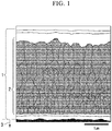
- Average layer thickness of the complex nitride or carbonitride layer 2 constituting the hard coating layer :
- FIG. 1 The schematic diagram of the cross section of the Ti, Al and Me complex nitride or carbonitride layer 2 constituting the hard coating layer of the present invention is shown in FIG. 1 .
- the hard coating layer included in the surface coated cutting tool of the present invention includes at least the Ti, Al and Me complex nitride or carbonitride layer 2 represented by the composition formula (Ti 1-x-y Al x Me y )(C z N 1-z ).
- the complex nitride or carbonitride layer 2 has a high hardness and an excellent wear resistance.
- the advantageous effect is distinctly exerted.
- the average layer thickness of the complex carbonitride layer is set to 1-20 ⁇ m.
- a more preferable average layer thickness is 3 ⁇ m to 15 ⁇ m.
- Ever more preferable average layer thickness is 4 ⁇ m to 10 ⁇ m.
- composition of the complex nitride or carbonitride layer 2 constituting the hard coating layer is a composition of the complex nitride or carbonitride layer 2 constituting the hard coating layer:
- the content ratio X avg which is the ratio of Al to the total amount of Ti Al, and Me
- the content ratio Y avg which is the ratio of Me to the total amount of Ti Al, and Me
- Z avg which is the ratio of C to a total amount of C and N
- the average Me content Y avg is set in the range of 0.005 ⁇ Y avg ⁇ 0.10.
- the sum of the average Al content X avg and the average Me content Y avg , X avg +Y avg is set to the range of 0.605 ⁇ X avg + Y avg ⁇ 0.95.
- one element selected from Si, Zr, B, V, and Cr is used as a specific component of Me.
- the Si component or the B component is used in such a way that Y avg is set to 0.005 or more, the hardness of the Ti, Al and Me complex nitride or carbonitride layer 2 is improved. Thus, wear resistance is improved.
- the Zr component has an effect strengthening the crystal grain boundaries.
- the V component improves toughness. Thus, by adding Zr and/or V, chipping resistance is improved further more.
- the Cr component improves oxidation resistance. Thus, further elongating the service life of the tool can be expected.
- the average C content ratio (in atomic ratio) Z avg included in the complex nitride or carbonitride layer 2 is extremely small amount in the range of 0 ⁇ y ⁇ 0.005
- adhesive strength of the complex nitride or carbonitride layer 2 to the tool body 3 or the lower layer is improved; and lubricity is also improved. Because of these, impact during cutting is alleviated. As a result, fracture resistance and chipping resistance of the complex nitride or carbonitride layer 2 are improved.
- the average C content ratio Z avg out of the range of 0 ⁇ Z avg ⁇ 0.005 is unfavorable since toughness of the complex nitride or carbonitride layer 2 is reduced, which leads to adversely reduced fracture resistance and chipping resistance. Because of the reason described above, the average C content ratio Z avg is set to 0 ⁇ Z avg ⁇ 0.005.
- X avg , Y avg , and Z avg are set to satisfy: 0.70 ⁇ X avg ⁇ 0.85; 0.01 ⁇ Y avg ⁇ 0.05; 0 ⁇ Z avg ⁇ 0.003; and 0.7 ⁇ X avg +Y avg ⁇ 0.90.
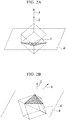
- Inclined angle frequency distribution of the ⁇ 111 ⁇ planes which are crystal planes of individual crystal grains having a NaCl type face-centered cubic structure in the Ti, Al and Me complex nitride or carbonitride layer 2 (the (Ti 1-x-y Al x Me y )(C z N 1-z ) layer):
- the hard coating layer made of the Ti, Al and Me complex nitride or carbonitride layer 2 has a high hardness while retaining the NaCl type face-centered cubic structure, in the case where, when crystal orientations of individual crystal grains having the NaCl type face-centered cubic structure in the above-described (Ti 1-x-y Al x Me y )(C z N 1-z ) layer of the present invention are analyzed from a vertical cross sectional direction with an electron beam backward scattering diffraction device, inclined angles of normal lines 6 of ⁇ 111 ⁇ planes, which are crystal planes of the crystal grains, relative to the direction of the normal line 5 of the surface of the tool body (the direction perpendicular to the surface of the tool body 4 in the polished cross section) are measured (refer FIGS.
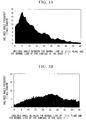
- the inclined angle frequency distribution is obtained by tallying frequencies present in each section after dividing inclined angles into sections in every 0.25° pitch in the range of 0 to 45° relative to the direction of the normal line among the inclined angles, the inclined angle frequency distribution pattern, in which the highest peak is present in the inclined angle section in the range of 0° to 12°, and the ratio of the sum of frequencies in the range of 0° to 12° to the overall frequency in the inclined angle frequency distribution is 35% or more, is observed. Furthermore, by having the above-described inclined angle frequency distribution pattern, adhesive strength between the hard coating layer and the body improves drastically.
- the coated tool configured as explained above, formation of chipping, fracture, peeling, and the like are suppressed, for example, even in the case where it is used in high-speed intermittent cutting of alloy steel or the like; and the coated tool exhibits excellent wear resistance.
- Crystal grains corresponding to an embodiment of the present invention, and ones for comparison, both of which have a cubic structure, are subjected to the above-described measurement method. Examples of the obtained inclined angle frequency distributions are shown as graphs in FIGS. 3A and 3B .
- Crystal grains constituting the complex nitride or carbonitride layer 2 and having the NaCl type face-centered cubic structure hereinafter, referred as "cubic":
- the average grain width W is adjusted to satisfy being 0.1 ⁇ m to 2.0 ⁇ m; and the average aspect ratio A is adjusted to satisfy being 2 to 10.
- the average aspect ratio A is the average value of aspect ratios "a” obtained relative to individual crystal grains.
- the average grain width W is the average value of grain widths "w” obtained relative to individual crystal grains.
- the aspect ratio "a” is the ratio of "l” to "w", l/w, of each crystal grain.
- the grain width "w” is the grain width in the direction parallel to the surface 4 of the tool body with respect to each cubic crystal grain in the complex nitride or carbonitride layer in the case where the cross section is observed and subjected to measurement from the direction perpendicular to the surface 4 of the tool body.
- the grain length is the grain length in the direction perpendicular to the surface of the tool body with respect to each cubic crystal grains in the complex nitride or carbonitride layer.
- the cubic crystal grains constituting the complex nitride or carbonitride layer 2 become the columnar structure and show excellent wear resistance. Contrary to that, it is unfavorable to have the average aspect ratio A less than 2 since it becomes hard to form the periodical composition distribution (concentration change, content ratio change), which is a unique feature of the present invention, in the crystal grains having the NaCl type face-centered cubic structure. In addition, it is unfavorable to have columnar crystals having the average aspect ratio A exceeding 10 since it becomes easy for cracks to grow in such a way to travel along planes along the periodical composition distribution in the cubic crystal phase, which is a unique feature of the present invention, and grain boundaries.
- the average grain width W of the cubic crystal grains constituting the Ti, Al and Me complex nitride or carbonitride layer 2 is 0.1 ⁇ m to 2.0 ⁇ m.
- the average aspect ratio A; and the average grain width W are 4 to 7; and 0.7 ⁇ m to 1.5 ⁇ m, respectively.
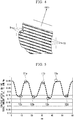
- FIG. 4 a periodic change of concentrations of Ti, Al and Me existing along one orientation among the equivalent crystal orientations expressed by ⁇ 001> of the cubic crystal grain; and the change of the Al content ratio x in the plane perpendicular to the orientation being small, are shown as a schematic diagram, regarding the crystal grains having the cubic crystal structure in the Ti, Al and Me complex nitride or carbonitride layer (hereinafter, referred as "the Ti, Al and Me complex nitride or carbonitride layer of the present invention") included in the hard coat layer of the present invention.
- FIG. 5 an example of a graph of a periodical concentration change of the content ratio x of Al to the total of the content ratios of Ti, Al and Me is shown.
- the graph is results of performing a liner analysis by the energy dispersive X-ray spectroscopy (EDS) with a transmission electron microscope on a crystal grain, in which a periodical concentration change of Ti, Al and Me exists, having a cubic crystal structure, on the cross section of the Ti, Al and Me complex nitride or carbonitride layer of the present invention.
- EDS energy dispersive X-ray spectroscopy
- composition of the crystal having the cubic crystal structure is expressed by the composition formula: (Ti 1-x-y Al x Me y )(C z N 1-z )
- each of x, y, and z are not a constant value, but fluctuate periodically
- strain is introduced in the crystal grain and hardness is improved.
- ⁇ x between X max and X min were less than 0.03
- the above-described strain in the cubic crystal grain would be lowered, and sufficient improvement of hardness would not be expected.
- the value x is a major indicator of the concentration change of Ti, Al and Me.
- X max is the average value of the local maximums 11a, 11b, 11c,... of the periodically fluctuating values of x, which is the content ratio x of Al in the composition formula.
- X min is the average value of the local minimums 12a, 12b, 12c, 12d,... of the periodically fluctuating values of x, which is the content ratio x of Al in the composition formula.
- the difference between X max and X min is set to 0.05 to 0.22. More preferably, it is set to 0.08 to 0.15.
- the period is set to 3 nm to 100 nm.
- a more preferable period of the concentration change is 15 nm to 80 nm. Even more preferably, it is 25 nm to 50 nm.
- the periodic content ratio change of Ti, Al and Me is aligned along with an orientation belonging to equivalent crystal orientations expressed by ⁇ 001 > in a cubic crystal grain, it becomes harder for a lattice defect due to strain in the crystal grain; and toughness is improved i regarding the cubic phase crystal grains, in which the periodic content ratio change of Ti, Al and Me exists in the complex nitride or carbonitride layer, having a cubic crystal structure.
- the content ratios of Ti, Al and Me are not changed substantially in the plane perpendicular to the orientation in which the above-described periodic content ratio change of Ti, Al and Me exists.
- the maximum ⁇ Xo of the change amount of the content ratio x of Al to the total of Ti, Al and Me is 0.01 or less in the above-described perpendicular plane.
- the period of the content ratio change along with an orientation belonging to equivalent crystal orientations expressed by ⁇ 001> in the cubic crystal grain is less than 3 nm, toughness is reduced. When it exceeds 100 nm, the effect of the hardness improvement cannot be exhibited sufficiently. Because of the reason described above, it is preferable that the period of the content ratio change is set to 3 nm to 100 nm.
- the period of the content ratio change is set to 25 nm to 50 nm.
- the region A (13) and the region B (14) existing in the crystal grain is shown as a schematic diagram, regarding the crystal grain, in which the periodical concentration change of Ti, Al and Me exists, having a cubic crystal structure on the cross section of the Ti, Al and Me complex nitride or carbonitride layer of the present invention.
- the toughness is improved by having the stain in two directions in the crystal grains; and the high toughness can be retained since the misfit in the boundary 15 between the region A (13) and the region B (14) does not occur because the boundary 15 between the region A (13) and the region B (14) is formed in a crystal plane belonging to equivalent crystal planes expressed by ⁇ 110 ⁇ , when the region A (13), in which the periodic content ratio change of Ti, Al and Me is aligned along with an orientation belonging to equivalent crystal orientations expressed by ⁇ 001> in a cubic crystal grain, and in a case where the orientation is defined as the orientation d A , the period along the orientation d A is 3 nm to 30 nm and the maximum ⁇ Xod A of the change of content ratio x of Al in the plane perpendicular to the orientation d A is 0.01 or less; and the region B (14), in which the periodic content ratio change of Ti, Al and Me is aligned along with an orientation, which is perpendicular to the orientation d A , belonging to
- X-ray diffraction experiment is performed using a X-ray diffraction apparatus using Cu-K ⁇ ray as the radiation source to obtain the lattice constant "a" of the above-described cubic crystal grain.
- the lattice constant "a" of the cubic crystal grain satisfies the relationship, 0.05a TiN +0.95a AlN ⁇ a ⁇ 0.4a TiN +0.6a AlN relative to the lattice constant a TiN of the cubic TiN (JCPDS00-038-1420), which is 4.24173 ⁇ , and the lattice constant a AlN of the cubic AlN (JCPDS00-046-1200), which is 4.045 ⁇ , the crystal grain shows an even higher hardness and a high thermal conductivity. As a result, the complex nitride or carbonitride layer obtains excellent wear resistance and excellent thermal shock resistance.
- X-ray diffraction is performed by using an X-ray diffraction apparatus in the condition of: 13° ⁇ 2 ⁇ 130° of the measurement range; 0.02° of the measurement width; and 0.5 second/step of the measurement time.
- the peak and crystal plane attributed to the Ti, Al and Me complex nitride or carbonitride layer having the cubic structure are identified from the obtained diffraction peaks.
- the interplanar spacing of the crystal planes is calculated from the wavelength of the used Cu-K ⁇ ray and the angle of the peak.
- the lattice constant a is the average value of the calculated lattice constants calculated from the values of the interplanar values.
- the area ratio of the columnar structure made of the individual crystal grains having the cubic structure is less than 70 area%, since the hardness is relatively reduced.
- the area ratio of the columnar structure made of the individual crystal grains having the cubic structure is 85 area% or more. More preferably, it is 95 area% or more.
- the complex nitride or carbonitride layer 2 of the present invention includes the Ti compound layer as the lower layer; the Ti compound layer is made of one layer or more than two layers selected from the group consisting of Ti carbide layer, Ti nitride layer, Ti carbonitride layer, Ti oxycarbide layer, and Ti oxycarbonitride layer; and the average total thickness of the Ti compound layer is 0.1 to 20 ⁇ m, and/or when the complex carbonitride layer includes aluminum oxide layer with the average thickness of 1-25 ⁇ m as the upper layer, the above-mentioned properties are not deteriorated.
- the complex nitride or carbonitride layer is included as the lower layer, when the average total layer thickness of the Ti compound layer exceeds 20 ⁇ m, the crystal grain is prone to be coarse, and chipping is prone to occur.
- the thickness of the lower layer is less than 0.1 ⁇ m, the improvement effect of the adhesive strength between the complex nitride or carbonitride layer 2 of the present invention and the lower layer cannot be expected.
- the thickness of the upper layer is less than 1 ⁇ m, the improvement effect of the wear resistance by depositing the upper layer becomes unnoticeable.
- the surface coated cutting tool of the present invention includes: a tool body made of any one of tungsten carbide-based cemented carbide, titanium carbonitride-based cermet, and cubic boron nitride-based ultra-high pressure sintered material; and a hard coating layer formed on a surface of the tool body.
- the hard coating layer includes at least a Ti, Al and Me complex nitride or carbonitride layer 2 having an average layer thickness of 1 ⁇ m to 20 ⁇ m.
- composition of the complex nitride or carbonitride layer 2 is expressed by a composition formula: (Ti 1-x-y Al x Me y )(C z N 1-z ), an average content ratio X avg , which is a ratio of Al to a total amount of Ti, Al and Me in the complex nitride or carbonitride layer 2; an average content ratio Y avg , which is a ratio of Me to the total amount of Ti, Al and Me in the complex nitride or carbonitride layer 2; and an average content ratio Z avg , which is a ratio of C to a total amount of C and N, satisfy 0.60 ⁇ X avg , 0.005 ⁇ Y avg ⁇ 0.10, 0 ⁇ Z avg ⁇ 0.005, and 0.605 ⁇ X avg + Y avg ⁇ 0.95, provided that each of X avg , Y avg and Z a
- the complex nitride or carbonitride layer 2 includes at least a phase of complex nitride or carbonitride having a NaCl type face-centered cubic structure (cubic crystal phase).
- a phase of complex nitride or carbonitride having a NaCl type face-centered cubic structure (cubic crystal phase).
- a difference ⁇ x between X max and X min is 0.03 to 0.25, X max and X min being an average value of local maximums of the periodically fluctuating Al content x and an average value of local minimums of the periodically fluctuating Al content x, respectively.
- a period along the direction of the normal line of the surface of the tool body is 3 nm to 100 nm in the crystal grains, in which the periodic content ratio change of Ti, Al and Me exists, having the NaCl type face-centered cubic structure.
- strain is introduced in the crystal grains having the cubic crystal structure in the complex nitride or carbonitride layer 2. Because of this, hardness of the crystal grain is improved; and toughness is also improved, while keeping the high wear resistance.
- the chipping resistant improvement effect is exhibited; the coated tool exhibits excellent cutting performance for a long-term usage compared to the conventional hard coating layer; and the longer service life of the coated tool is achieved.
- the surface coated cutting tool of the present invention includes: a cemented carbide tool body, which is made of any one of tungsten carbide-based cemented carbide, titanium carbonitride-based cermet, and cubic boron nitride-based ultra-high pressure sintered material; and a hard coating layer 1 formed on a surface of the tool body 3.
- the hard coating layer 1 includes at least a Ti, Al and Me complex nitride or carbonitride layer 2, which has an average layer thickness of 1 ⁇ m to 20 ⁇ m.
- composition of the complex nitride or carbonitride layer 2 is expressed by a composition formula: (Ti 1-x-y Al x Me y )(C z N 1-z ), an average content ratio X avg , which is a ratio of Al to a total amount of Ti, Al and Me; an average content ratio Y avg , which is a ratio of Me to the total amount of Ti, Al and Me; and an average content ratio Z avg , which is a ratio of C to a total amount of C and N, satisfy 0.60 ⁇ X avg , 0.005 ⁇ Y avg ⁇ 0.10, 0 ⁇ Z avg ⁇ 0.005, and 0.605 ⁇ X avg + Y avg ⁇ 0.95, provided that each of X avg , Y avg and Z avg is in atomic ratio.
- the crystal grains constituting the complex nitride or carbonitride layer 2 include at least crystal grains having a cubic crystal structure.
- inclined angles of normal lines 6 of ⁇ 111 ⁇ planes, which are crystal planes of the crystal grains, relative to an direction of a normal line of the surface of the tool body are measured, and an inclined angle frequency distribution is obtained by tallying frequencies present in each section after dividing inclined angles into sections in every 0.25° pitch in a range of 0 to 45° relative to the direction of the normal line among the inclined angles, a highest peak is present in an inclined angle section in a range of 0° to 12°, a ratio of a sum of frequencies in the range of 0° to 12° to an overall frequency in the inclined angle frequency distribution is 35% or more.
- a difference ⁇ x between X max and X min is 0.03 to 0.25, X max and X min being an average value of local maximums of the periodically fluctuating Al content x and an average value of local minimums of the periodically fluctuating Al content x, respectively.
- a period along the direction of the normal line of the surface of the tool body is 3 nm to 100 nm in the crystal grains, in which the periodic content ratio change of Ti, Al and Me exists, having the NaCl type face-centered cubic structure.
- the chipping resistance is improved; the coated tool exhibits excellent cutting performance for a long-term usage compared to the conventional hard coating layer; and the longer service life of the coated tool is achieved.
- any form of embodiment can be chosen.
- the WC powder, the TiC powder, the TaC powder, the NbC powder, the Cr 3 C 2 powder, and the Co powder all of which had the average grain sizes of 1-3 ⁇ m.
- These raw material powders were blended in the blending composition shown in Table 1.
- wax was added to the blended mixture, and further mixed in acetone for 24 hours with a ball mill.
- the mixtures were press-molded into green compacts with a predetermined shape under pressure of 98 MPa.
- the obtained green compacts were sintered in vacuum in the condition of 5 Pa vacuum at the predetermined temperature in the range of 1370-1470°C for 1 hour retention.
- the tool bodies A-C which had the insert-shape defined by ISO-SEEN1203AFSN and made of WC-based cemented carbide, were produced.
- the coated tools of the present invention 1-15 were produced by performing the thermal CVD method for predetermined times to form the hard coating layer made of the (Ti 1-x-y Al x Me y )(C z N 1-z ) layer having the intended layer thicknesses shown in Table 7 on the surfaces of the tool bodies A to D by using a chemical vapor deposition apparatus.
- the formation condition is as shown in Table 4.
- the gas group A was made of NH 3 and N 2 .
- the gas group B was made of TiCl 4 , Al(CH 3 ) 3 , AlCl 3 , MeCl n (any one of SiCl 4 , ZrCl 4 , BCl 3 , VCl 4 , and CrCl 2 ), NH 3 , N 2 , and H 2 . Suppling method of each of gases was as follows.
- the composition of the reaction (volume% to the total amount including the gas group A and the gas group B) gas included: 1.0% to 1.5% of NH 3 , 0% to 5% of N 2 and 55% to 60% of H 2 as the components from the gas group A; and 0.6% to 0.9% of AlCl 3 , 0.2% to 0.3% of TiCl 4 , 0% to 0.5% of Al(CH 3 ) 3 , 0.1% to 0.2% of MeCl n (any one of SiCl 4 , ZrCl 4 , BCl 3 , VCl 4 , and CrCl 2 ), 0.0% to 12.0% of N 2 , and the H 2 balance as the components from the gas group B.
- the pressure of the reaction atmosphere was 4.5 to 5.0 kPa.
- the temperature of the reaction atmosphere was 700 to 900°C.
- the supplying period was 1 to 5 seconds.
- the gas supplying time per one period was 0.15 to 0.25 second.
- the phase difference in supplying the gas groups A and B was 0.10
- the lower layer and/or the upper layer were formed as shown in Table 6 in the formation condition shown in Table 3.
- the hard coating layers including a Ti, Al and Me complex nitride or carbonitride layer were deposited on the surfaces of the tool bodies A-D, in the conditions shown in Tables 5, in the intended total layer thicknesses ( ⁇ m) shown in Table 8.
- the comparative coated tools 1-15 were produced by forming the hard coating layer in the coating process of the (Ti 1-x-y Al x Me y )(C z N 1-z ) layer in such a way that the composition of the reaction gas on the surfaces of the tool bodies did not change by time.
- the lower layer and the upper layer shown in Table 6 were formed in the formation condition shown in Table 3.
- the existence of the peak of the frequencies existing in the range of 0° to 12° was confirmed; and the ratio of the frequencies existing in the range of 0° to 12° was obtained, as explained above.
- the cross section of the hard coating layer in the direction perpendicular to the surface of the tool body, which was in the polished state, was set in the lens barrel of the field emission scanning electron microscope.
- the Ti, Al and Me complex nitride or carbonitride layers constituting the hard coating layers of the coated tools of the present invention 1-15 and the comparative coated tools 1-15 were observed in multiple viewing fields by using the scanning electron microscope (magnification: 5,000 times, and 20,000 times).
- the period was 3 nm to 100 nm; and the value of ⁇ x, which was the difference of the average value of the local maximums and the average value of the local minimums, was in the range of 0.03 to 0.25 in the coated tools of the present invention 1-15.
- an electron beam was irradiated to the polished surface of the samples from the surface side of the sample by using EPMA (Electron-Probe-Micro-Analyzer). Then, the average Al content ratio X avg and the average Me ratio Y avg , were obtained from 10-point average of the analysis results of the characteristic X-ray.
- the average C content ratio Z avg was obtained by secondary-ion-mass-spectroscopy (SIMS).
- the average C content ratio Z avg indicates the average value in the depth direction of the Ti, Al and Me complex nitride or carbonitride layer.
- the inevitably included C content ratio which was included without the intentional use of the gas containing C as the raw material gas, was excluded.
- the content ratio (atomic ratio) of the C component included in the complex nitride or carbonitride layer in the case where the supply amount of Al(CH 3 ) 3 was set to 0 was obtained as the inevitably included C content ratio. Then, the value, in which the inevitably included C content ratio was subtracted from the content ratio of the C component (atomic ratio) included in the complex nitride or carbonitride layer in the case where Al(CH 3 ) 3 was intentionally supplied, was obtained as Z avg .
- the average aspect ratio A and the average grain width W were obtained as explained below.
- the grain width "w" in the direction parallel to the surface of the tool body; and the grain length "l” in the direction perpendicular to the surface of the tool body were measured by using a scanning electron microscope (magnification: 5,000 times, 20,000 times) from the cross sectional direction perpendicular to the tool body.
- the average grain width W was obtained as the average value of the grain widths "w" obtained from each of the crystal grains.
- observation of the micro region of the complex nitride or carbonitride layer 2 was performed by using a transmission electron microscope; and the plane analysis from the cross section side was performed by using the energy dispersive X-ray spectroscopy (EDS) method.
- EDS energy dispersive X-ray spectroscopy
- the linear analysis was performed along the direction perpendicular to the orientation among the equivalent crystal orientations expressed by ⁇ 001> of the cubic crystal grain having the periodical concentration change of Ti, Al and Me in the length corresponding to the section of the above-described five periods. Then, the difference between the maximum and the minimum of the content ratio x of Al in the section was obtained as the maximum ⁇ Xo of the change of the content ratio in the plane perpendicular to the direction perpendicular to the orientation among the equivalent crystal orientations expressed by ⁇ 001> of the cubic crystal grain having the periodical concentration change of Ti, Al and Me.
- the difference of the maximum and the minimum of the content ratio x of Al in the section was obtained as the maximum ⁇ Xod A of the change of the content ratio in the plane perpendicular to the direction perpendicular to the orientation among the equivalent crystal orientations expressed by ⁇ 001> of the cubic crystal grain having the periodical concentration change of Ti, Al and Me by obtaining the period of the concentration change along the orientation d A and performing the linear analysis along the direction perpendicular to the orientation d A in the section having the length corresponding to five periods.
- the difference of the maximum and the minimum of the content ratio x of Al in the section was obtained as the maximum ⁇ Xod B of the change of the content ratio in the plane perpendicular to the direction perpendicular to the orientation among the equivalent crystal orientations expressed by ⁇ 001> of the cubic crystal grain having the periodical concentration change of Ti, Al and Me by obtaining the period of the concentration change along the orientation d B and performing the linear analysis along the direction perpendicular to the orientation d B in the section having the length corresponding to five periods.
- Such confirmations of the period were performed in at least one crystal grain in the viewing field of the micro region of the complex nitride or carbonitride layer using the transmission scanning electron microscope.
- the average value was calculated from the values evaluated in at least one crystal grain in the viewing field of the micro region of the complex nitride or carbonitride layer using the transmission scanning electron microscope in each of the region A and the region B in the specific crystal grain.
- Type Blending composition (mass%) Co TiC TaC NbC Cr 3 C 2 WC Tool body A 8.0 1.5 - 3.0 0.4 balance B 8.5 - 1.8 0.2 - balance C 7.0 - - - - balance
- Type Blending composition (mass%) Co Ni ZrC NbC Mo 2 C WC TiCN Tool body D 8 5 1 6 6 10 balance
- Layers constituting the hard coating layer Formation condition (reaction pressure and temperature are indicated by kPa and °C, respectively)
- Units of pressure and temperature of the reaction atmosphere are kPa and °C, respectively) Process type Formation symbol Composition of the reaction gas group A (volume%) Gas group A Composition of the reaction gas group B (volume%) Gas group B Phase difference of supplying the gas groups A and B (second) Reaction atmosphere Supply period (second) Supply time per a period (second) Supply period (second) Supply time per a period (second) Pressure Temperature Si-A NH 3 : 1.2 %, N 2 : 0 %, H 2 : 58 %, 2 0.15 AlCl 3 : 0.7 %, TiCl 4 : 0.2 %, SiCl 4 : 0.1 %, N 2 : 5%, Al(CH 3 ) 3 : 0%, balance H 2 2 0.15 0.10 4.5 750 Si-B NH 3 : 1.5 %, N 2 : 2 %, H 2 : 57 %, 4 0.25 AlCl 3 : 0.8 %, TiCl 4 : 0.3 %,
- Units of pressure and temperature of the reaction atmosphere are kPa and °C, respectively) Process type Formation symbol Composition of the reaction gas group A (volume%) Gas group A Composition of the reaction gas group B (volume%) Gas group B Phase difference of supplying the gas groups A and B (second) Reaction atmosphere Supply period (second) Supply time per a period (second) Supply period (second) Supply time per a period (second) Pressure Temperature Si-a NH 3 : 0.7 %, N 2 : 2 %, H 2 : 57 %, - - AlCl 3 : 0.9 %, TiCl 4 : 0.1 %, SiCl 4 : 0.1 %, N 2 : 5 %, Al(CH 3 ) 3 : 0 %, balance H 2 - - - 6.0 800 Si-b NH 3 : 1.3 %, N 2 : 0 %, H 2 : 64 %, - - AlCl 3 : 0.7 %, TiCl 4 :
- each of the coated tools described above was clamped on the face milling cutter made of tool steel with the cutter diameter of 125 mm by a fixing jig. Then, the cutting test of high-speed-dry-center-cutting-face-milling was performed on the coated tools of the present invention 1-15; and the comparative coated tools 1-15, in the clamped-state.
- the cutting test of high-speed-dry-center-cutting-face-milling is a type of high speed intermittent cutting of alloy steel, and was performed under the condition shown below. After the test, width of flank wear of the cutting edge was measured.
- the WC powder, the TiC powder, the ZrC powder, the TaC powder, the NbC powder, the Cr 3 C 2 powder, the TiN powder, and the Co powder all of which had the average grain sizes of 1-3 ⁇ m.
- These raw material powders were blended in the blending composition shown in Table 10.
- wax was added to the blended mixture, and further mixed in acetone for 24 hours with a ball mill.
- the mixtures were press-molded into green compacts with a predetermined shape under pressure of 98 MPa.
- the obtained green compacts were sintered in vacuum in the condition of 5 Pa vacuum at the predetermined temperature in the range of 1370-1470°C for 1 hour retention.
- the tool bodies ⁇ - ⁇ which had the insert-shape defined by ISO standard CNMG120412 and made of WC-based cemented carbide, were produced by performing honing (R: 0.07mm) on the cutting edge part.
- honing R: 0.09mm
- the coated tools of the present invention 16-30 were produced by performing the thermal CVD method in the formation condition shown in Table 4 for predetermined times to deposit the (Ti l-x-y Al x Me y )(C z N l-z ) layers shown in Table 13 on the surfaces of the tool bodies ⁇ to ⁇ and the tool body ⁇ by using a chemical vapor deposition apparatus as in Example 1.
- the lower layer and/or the upper layer were formed as shown in Table 12 in the formation condition shown in Table 3.
- the comparative coated tools 16-30 indicated in Table 14 were deposited the hard coating layer on the surface of the tool bodies ⁇ - ⁇ and the tool body ⁇ in intended thicknesses shown in Table 14 using a chemical vapor deposition apparatus in the conditions indicated in Tables 5 in the same manner.
- the lower layer and/or the upper layer shown in Table 12 were formed in the forming condition shown in Table 3.
- the cross sections of each constituting layers were subjected to measurement by the scanning electron microscopy (magnification: 20,000); and the average layer thicknesses were obtained by averaging the layer thicknesses measured at 5 points within the observation viewing field. In any measurement, the obtained layer thickness was practically the same as the intended total layer thicknesses shown in Tables 13 and 14.
- Type Blending composition (mass%) Co TiC ZrC TaC NbC Cr 3 C 2 TiN WC Tool body ⁇ 6.5 - 1.5 - 2.9 0.1 1.5 balance ⁇ 7.6 2.6 - 4.0 0.5 - 1.1 balance ⁇ 6.0 - - - - - - balance
- Type Blending composition (mass%) Co Ni NbC WC TiCN Tool body ⁇ 11 4 6 15 balance
- Type Lower layer (The number at the bottom indicates the intended average layer thickness ( ⁇ m))
- Upper layer (The number at the bottom indicates the intended average layer thickness ( ⁇ m)) 1st layer 2nd layer 3rd layer 4th layer 1st layer 2nd layer 3rd layer 4th layer
- each of the coated tools described above was clamped on the front end part of the bit made of tool steel by a fixing jig. Then, the dry high-speed intermittent cutting test on alloy steel and the wet high-speed intermittent cutting test on a cast iron were performed on the coated tools of the present invention 16-30; and the comparative coated tools 16-30, in the clamped-state. After the test, width of flank wear of the cutting edge was measured.
- the tool bodies 2A and 2B were produced by the process explained below.
- the cBN powder, the TiN powder, the TiCN powder, the TiC powder, the Al powder, and Al 2 O 3 powder, all of which had the average grain sizes of 0.5-4 ⁇ m were prepared. These raw material powders were blended in the blending composition shown in Table 16. Then, the mixtures were wet-mixed for 80 hours with a ball mill. After drying, the mixtures were press-molded into green compacts with a dimension of: diameter of 50 mm; and thickness of 1.5 mm, under pressure of 120 MPa.
- the obtained green compacts were sintered in vacuum in the condition of 1 Pa vacuum at the predetermined temperature in the range of 900-1300°C for 60 minutes retention to obtain preliminary sintered bodies for the cutting edge pieces.
- the obtained preliminary sintered bodies were placed on separately prepared supporting pieces made of WC-based cemented carbide, which had the composition of: 8 mass% of Co; and the WC balance, and the dimension of: diameter of 50 mm; and thickness of 2 mm. They were inserted into a standard ultra-high pressure sintering apparatus in the stacked state. Then, they were subjected to ultra-high-pressure sintering in the standard condition of: 4 GPa of pressure; a predetermined temperature within the range of 1200-1400°C; and 0.8 hour of the retention time.
- the top and bottom surfaces of the sintered bodies were grinded by using a diamond grind tool. Then, they were divided into a predetermined dimension with a wire-electrical discharge machine. Then, they were brazed on the brazing portion (corner portion) of the insert main tool body made of WC-based cemented carbide, which had the composition of: 5 mass% of Co; 5 mass% of TaC; and the WC balance, and the shape defined by ISO CNGA120412 standard (the diamond shape of: thickness of 4.76 mm; and inscribed circle diameter of 12.7 mm) by using the brazing material made of Ti-Zr-Cu alloy having composition made of: 37.5% of Zr; 25% of Cu; and the Ti balance in volume %.
- the coated tools of the present invention 31-40 indicated in Tables 18 were deposited the hard coating layer including at least the (Ti 1-x-y Al x Me y )(C z N 1-z ) layer related to the present invention on the surfaces of the tool bodies 2A and 2B in the intended layer thicknesses using a chemical vapor deposition apparatus in the conditions indicated in Table 4 as in the same method as Example 1.
- the lower layer and/or the upper layer shown in Table 17 were formed in the formation condition shown in Table 3.
- the comparative coated tools 31-40 indicated in Table 19 were deposited the hard coating layer including at least the (Ti 1-x-y Al x Mey)(C z N 1-z ) layer on the surface of the tool bodies 2A and 2B in intended thicknesses using a chemical vapor deposition apparatus in the conditions indicated in Table 5.
- the lower layer and/or the upper layer shown in Table 17 were formed in the formation conditions shown in Table 3 in the comparative coated tools 34-39.
- the average layer thicknesses; the average Al content ratio X avg ; the average Me content ratio Y avg ; the average C content ratio Z avg ; the inclined angle frequency distribution; the difference ⁇ x of the periodical concentration change ( X max -X min ) and the period; the lattice constant "a"; the average grain width W and the average aspect ratio A of the crystal grains; and the area ratio occupied by the cubic crystal phase in the crystal grains, were obtained as in the method indicated in Example 1.
- each coated tool was screwed on the tip of the insert holder made of tool steel by a fixing jig. Then, the dry high speed intermittent cutting test of carbolized steel explained below were performed on the coated tools of the present invention 31-40; and the comparative coated tools 31-40. After the tests, width of flank wear of the cutting edge was measured.
- Results of the cutting test are shown in Table 20.
- Table 20 Type Width of wear on the flank face (mm)
- Coated tools of the present invention 31 0.11 Comparative coated tools 31 1.7* 32 0.09 32 2.2* 33 0.13 33 1.5* 34 0.10 34 2.9* 35 0.08 35 1.8* 36 0.11 36 2.0* 37 0.09 37 2.9* 38 0.12 38 3.3* 39 0.11 39 2.8* 40 0.07 40 3.1*
- Asterisk marks (*) in the column of the comparative coated tools indicate the cutting time (min) until they reached to their service lives due to occurrence of chipping.
- the tool bodies A to C made of WC-based cemented carbide were deposited by the process in which, as raw material powders, the WC powder, the TiC powder, the TaC powder, the NbC powder, the Cr 3 C 2 powder, and Co powder, all of which had the average grain sizes of 1-3 ⁇ m, were prepared. These raw material powders were blended in the blending composition shown in Table 1. Then, the mixtures were subjected ball mill mixing for 24 hours in acetone after adding wax. After vacuum drying, the mixtures were press-molded into green compacts in the predetermined shape at the pressure of 98MPa.
- the obtained green compacts were sintered in vacuum in the condition of 5 Pa vacuum at the predetermined temperature in the range of 1370 °C-1470°C for retention time of 1 hour.
- the tool bodies A to C made of WC-based cemented carbide with the insert shape defined by ISO SEEN1203AFSN standard were produced.
- the coated tools of the present invention 41-55 were deposited the (Ti 1-x-y Al x Me y )(C z N 1-z ) layer shown in Table 23 on the surfaces of the tool bodies A to C by performing a thermal CVD method for a predetermined time in the formation condition shown in Table 4 with a chemical vapor deposition apparatus.
- the lower layer and/or the upper layer shown in Table 22 were formed in the formation condition shown in Table 3.
- the comparative coated tools 41-55 indicated in Table 24 were deposited the hard coating layer on the surfaces of the tool bodies A to C too as in the coated tools of the present invention by using a chemical vapor deposition apparatus in the condition shown in Table 21 and in the intended layer thickness shown in Table 24.
- the lower layer and/or the upper layer shown in Table 22 were formed in the formation conditions shown in Table 3 in the comparative coated tools 45-52.
- each coated tool was clamped on the tip of the cutter made of tool steel with the cutter diameter of 125 mm by a fixing jig. Then, center cut cutting test in high speed wet face milling, which is one of high speed intermittent cutting of carbolized steel, was performed on the coated tools of the present invention 41-55; and the comparative coated tools 41-55 in the condition described below. After the tests, width of flank wear of the cutting edge was measured.
- Results of the cutting test are shown in Table 25.
- Table 25 Type Width of wear on the flank face (mm)
- Type Results of the cutting test (min) 41 0.15 41 4.0* 42 0.18 42 3.8* 43 0.19 43 4.5* 44 0.18 44 4.7* 45 0.14 45 2.8* Coated tools of the present invention 46 0.12 Comparative coated tools 46 4.3* 47 0.17 47 2.1* 48 0.16 48 2.4* 49 0.13 49 1.6* 50 0.10 50 3.6* 51 0.16 51 3.1* 52 0.11 52 2.9* 53 0.12 53 2.3* 54 0.18 54 3.2* 55 0.13 55 2.6*
- Asterisk marks (*) in the column of the comparative coated tools indicate the cutting time (min) until they reached their service lives due to occurrence of chipping.
- the surface coated cutting tools of the present invention showed an excellent chipping resistance and an excellent fracture resistance even if they were used in high speed intermittent cutting. It is clear that they exhibited an excellent wear resistance for a long-term usage because of these.
- the coated tool of the present invention can be utilized in high speed intermittent cutting of a wide variety of works as well as of alloy steel as described above. Furthermore, the coated tool of the present invention exhibits an excellent chipping resistance and an excellent wear resistance for a long-term usage. Thus, the coated tool of the present invention can be sufficiently adapted to high-performance cutting apparatuses; and labor-saving, energy-saving, and cost-saving of cutting.
Landscapes
- Chemical & Material Sciences (AREA)
- Engineering & Computer Science (AREA)
- Mechanical Engineering (AREA)
- Chemical Kinetics & Catalysis (AREA)
- Materials Engineering (AREA)
- Metallurgy (AREA)
- Organic Chemistry (AREA)
- Inorganic Chemistry (AREA)
- General Chemical & Material Sciences (AREA)
- Ceramic Engineering (AREA)
- Cutting Tools, Boring Holders, And Turrets (AREA)
- Chemical Vapour Deposition (AREA)
Applications Claiming Priority (3)
| Application Number | Priority Date | Filing Date | Title |
|---|---|---|---|
| JP2014240834 | 2014-11-28 | ||
| JP2015229738A JP6617917B2 (ja) | 2014-11-28 | 2015-11-25 | 表面被覆切削工具 |
| PCT/JP2015/083400 WO2016084938A1 (fr) | 2014-11-28 | 2015-11-27 | Outil de coupe à revêtement de surface |
Publications (2)
| Publication Number | Publication Date |
|---|---|
| EP3225338A1 true EP3225338A1 (fr) | 2017-10-04 |
| EP3225338A4 EP3225338A4 (fr) | 2018-08-01 |
Family
ID=56121499
Family Applications (1)
| Application Number | Title | Priority Date | Filing Date |
|---|---|---|---|
| EP15863164.8A Withdrawn EP3225338A4 (fr) | 2014-11-28 | 2015-11-27 | Outil de coupe à revêtement de surface |
Country Status (5)
| Country | Link |
|---|---|
| US (1) | US20170342552A1 (fr) |
| EP (1) | EP3225338A4 (fr) |
| JP (1) | JP6617917B2 (fr) |
| KR (1) | KR20170086045A (fr) |
| CN (1) | CN107000069A (fr) |
Families Citing this family (4)
| Publication number | Priority date | Publication date | Assignee | Title |
|---|---|---|---|---|
| JP7183519B2 (ja) * | 2018-09-28 | 2022-12-06 | 三菱マテリアル株式会社 | 硬質被覆層が優れた耐チッピング性を発揮する表面切削工具 |
| WO2021006739A1 (fr) * | 2019-07-11 | 2021-01-14 | Knight Acquisition B.V. | Lame de scie ou autre outil de coupe comprenant un revêtement |
| JP7543975B2 (ja) | 2021-04-30 | 2024-09-03 | 住友電気工業株式会社 | 切削工具 |
| CN117836078A (zh) * | 2021-08-19 | 2024-04-05 | 株式会社Moldino | 包覆工具 |
Family Cites Families (10)
| Publication number | Priority date | Publication date | Assignee | Title |
|---|---|---|---|---|
| JP4112836B2 (ja) * | 2001-06-19 | 2008-07-02 | 株式会社神戸製鋼所 | 切削工具用硬質皮膜を形成するためのターゲット |
| JP4672442B2 (ja) * | 2005-05-31 | 2011-04-20 | オーエスジー株式会社 | 硬質積層被膜、および硬質積層被膜被覆工具 |
| JP5287125B2 (ja) * | 2008-10-15 | 2013-09-11 | 三菱マテリアル株式会社 | 硬質被覆層がすぐれた耐欠損性、耐摩耗性を発揮する表面被覆切削工具 |
| JP5247377B2 (ja) * | 2008-11-26 | 2013-07-24 | 京セラ株式会社 | 切削工具 |
| JP5321975B2 (ja) * | 2009-09-24 | 2013-10-23 | 住友電工ハードメタル株式会社 | 表面被覆切削工具 |
| DE102009046667B4 (de) * | 2009-11-12 | 2016-01-28 | Fraunhofer-Gesellschaft zur Förderung der angewandten Forschung e.V. | Beschichtete Körper aus Metall, Hartmetal, Cermet oder Keramik sowie Verfahren zur Beschichtung derartiger Körper |
| JP5939508B2 (ja) * | 2012-07-25 | 2016-06-22 | 三菱マテリアル株式会社 | 高速断続切削加工で硬質被覆層がすぐれた耐チッピング性を発揮する表面被覆切削工具 |
| JP6037113B2 (ja) * | 2012-11-13 | 2016-11-30 | 三菱マテリアル株式会社 | 高速断続切削加工で硬質被覆層がすぐれた耐チッピング性を発揮する表面被覆切削工具 |
| JP6268530B2 (ja) * | 2013-04-01 | 2018-01-31 | 三菱マテリアル株式会社 | 硬質被覆層がすぐれた耐チッピング性を発揮する表面被覆切削工具 |
| JP6284034B2 (ja) * | 2014-09-25 | 2018-02-28 | 三菱マテリアル株式会社 | 硬質被覆層がすぐれた耐チッピング性を発揮する表面被覆切削工具 |
-
2015
- 2015-11-25 JP JP2015229738A patent/JP6617917B2/ja active Active
- 2015-11-27 US US15/531,295 patent/US20170342552A1/en not_active Abandoned
- 2015-11-27 EP EP15863164.8A patent/EP3225338A4/fr not_active Withdrawn
- 2015-11-27 CN CN201580064514.6A patent/CN107000069A/zh active Pending
- 2015-11-27 KR KR1020177013914A patent/KR20170086045A/ko unknown
Also Published As
| Publication number | Publication date |
|---|---|
| EP3225338A4 (fr) | 2018-08-01 |
| JP6617917B2 (ja) | 2019-12-11 |
| CN107000069A (zh) | 2017-08-01 |
| US20170342552A1 (en) | 2017-11-30 |
| JP2016107397A (ja) | 2016-06-20 |
| KR20170086045A (ko) | 2017-07-25 |
Similar Documents
| Publication | Publication Date | Title |
|---|---|---|
| EP2982466B1 (fr) | Outil de coupe revêtu en surface | |
| EP2891536B1 (fr) | Outil de coupe à surface enrobée | |
| EP3103572B1 (fr) | Outil de coupe à surface revêtue dans lequel une couche de revêtement dur présente une excellente résistance à l'écaillage | |
| EP2823923B1 (fr) | Outil de coupe doté d'un revêtement de surface ayant à l'intérieur de celui-ci une couche de revêtement dure capable de présenter une excellente résistance à l'écaillage pendant un travail de coupe intermittente à grande vitesse | |
| JP6478100B2 (ja) | 硬質被覆層がすぐれた耐チッピング性を発揮する表面被覆切削工具 | |
| EP3127637B1 (fr) | Outil de coupe revêtu en surface et procédé de production associé | |
| US10307830B2 (en) | Surface-coated cutting tool having hard coating layer that exhibits excellent chipping resistance | |
| EP3199275A1 (fr) | Outil de coupe revêtu en surface dans lequel une couche de revêtement dure présente une excellente résistance à l'écaillage | |
| EP3202515A1 (fr) | Outil de coupe revêtu en surface avec excellente résistance aux copeaux | |
| JP6590255B2 (ja) | 硬質被覆層がすぐれた耐チッピング性を発揮する表面被覆切削工具 | |
| EP3150310B1 (fr) | Outil de coupe à revêtement de surface comprenant une couche de revêtement dure qui présente une excellente résistance à l'écaillage | |
| EP3213840A1 (fr) | Outil de coupe à revêtement de surface | |
| EP3225338A1 (fr) | Outil de coupe à revêtement de surface | |
| EP3903974A1 (fr) | Outil de coupe doté d'un revêtement de surface | |
| JP6709536B2 (ja) | 硬質被覆層がすぐれた耐チッピング性を発揮する表面被覆切削工具 | |
| JP6957824B2 (ja) | 硬質被覆層が優れた耐チッピング性、耐摩耗性を発揮する表面被覆切削工具 | |
| EP3858524A1 (fr) | Outil de coupe à revêtement superficiel doté d'une couche de revêtement dur, présentant une excellente résistance à l'écaillage | |
| WO2016084938A1 (fr) | Outil de coupe à revêtement de surface |
Legal Events
| Date | Code | Title | Description |
|---|---|---|---|
| PUAI | Public reference made under article 153(3) epc to a published international application that has entered the european phase |
Free format text: ORIGINAL CODE: 0009012 |
|
| 17P | Request for examination filed |
Effective date: 20170602 |
|
| AK | Designated contracting states |
Kind code of ref document: A1 Designated state(s): AL AT BE BG CH CY CZ DE DK EE ES FI FR GB GR HR HU IE IS IT LI LT LU LV MC MK MT NL NO PL PT RO RS SE SI SK SM TR |
|
| AX | Request for extension of the european patent |
Extension state: BA ME |
|
| DAV | Request for validation of the european patent (deleted) | ||
| DAX | Request for extension of the european patent (deleted) | ||
| A4 | Supplementary search report drawn up and despatched |
Effective date: 20180703 |
|
| RIC1 | Information provided on ipc code assigned before grant |
Ipc: C23C 16/36 20060101ALI20180627BHEP Ipc: C23C 16/34 20060101ALI20180627BHEP Ipc: C23C 16/455 20060101ALI20180627BHEP Ipc: C23C 28/04 20060101ALI20180627BHEP Ipc: B23B 27/14 20060101AFI20180627BHEP |
|
| STAA | Information on the status of an ep patent application or granted ep patent |
Free format text: STATUS: THE APPLICATION IS DEEMED TO BE WITHDRAWN |
|
| 18D | Application deemed to be withdrawn |
Effective date: 20190131 |