EP3222239A1 - Outil de traitement et système de traitement - Google Patents
Outil de traitement et système de traitement Download PDFInfo
- Publication number
- EP3222239A1 EP3222239A1 EP15861368.7A EP15861368A EP3222239A1 EP 3222239 A1 EP3222239 A1 EP 3222239A1 EP 15861368 A EP15861368 A EP 15861368A EP 3222239 A1 EP3222239 A1 EP 3222239A1
- Authority
- EP
- European Patent Office
- Prior art keywords
- temperature
- living tissue
- holding
- blade
- high frequency
- Prior art date
- Legal status (The legal status is an assumption and is not a legal conclusion. Google has not performed a legal analysis and makes no representation as to the accuracy of the status listed.)
- Granted
Links
- 238000011282 treatment Methods 0.000 title claims abstract description 200
- 238000010438 heat treatment Methods 0.000 claims abstract description 55
- 238000010292 electrical insulation Methods 0.000 claims description 16
- 230000007246 mechanism Effects 0.000 description 19
- 239000000463 material Substances 0.000 description 18
- 238000007789 sealing Methods 0.000 description 15
- 239000011248 coating agent Substances 0.000 description 11
- 238000000576 coating method Methods 0.000 description 11
- 102000004169 proteins and genes Human genes 0.000 description 10
- 108090000623 proteins and genes Proteins 0.000 description 10
- 230000006870 function Effects 0.000 description 9
- 230000004048 modification Effects 0.000 description 8
- 238000012986 modification Methods 0.000 description 8
- 230000009471 action Effects 0.000 description 7
- 230000007423 decrease Effects 0.000 description 7
- 230000005540 biological transmission Effects 0.000 description 6
- 230000008859 change Effects 0.000 description 5
- 230000018044 dehydration Effects 0.000 description 5
- 238000006297 dehydration reaction Methods 0.000 description 5
- 230000000977 initiatory effect Effects 0.000 description 5
- 239000000956 alloy Substances 0.000 description 4
- 230000001112 coagulating effect Effects 0.000 description 4
- 238000004925 denaturation Methods 0.000 description 4
- 230000036425 denaturation Effects 0.000 description 4
- 238000010586 diagram Methods 0.000 description 4
- 238000003825 pressing Methods 0.000 description 4
- 229910000881 Cu alloy Inorganic materials 0.000 description 3
- 230000001154 acute effect Effects 0.000 description 3
- 230000003247 decreasing effect Effects 0.000 description 3
- 229910000990 Ni alloy Inorganic materials 0.000 description 2
- 238000005452 bending Methods 0.000 description 2
- 238000000034 method Methods 0.000 description 2
- 229910000838 Al alloy Inorganic materials 0.000 description 1
- RYGMFSIKBFXOCR-UHFFFAOYSA-N Copper Chemical compound [Cu] RYGMFSIKBFXOCR-UHFFFAOYSA-N 0.000 description 1
- 229910052802 copper Inorganic materials 0.000 description 1
- 239000010949 copper Substances 0.000 description 1
- 230000000694 effects Effects 0.000 description 1
- 239000010408 film Substances 0.000 description 1
- 238000009413 insulation Methods 0.000 description 1
- 230000002093 peripheral effect Effects 0.000 description 1
- 239000004033 plastic Substances 0.000 description 1
- 239000004810 polytetrafluoroethylene Substances 0.000 description 1
- 229920001343 polytetrafluoroethylene Polymers 0.000 description 1
- 239000011347 resin Substances 0.000 description 1
- 229920005989 resin Polymers 0.000 description 1
- 239000000523 sample Substances 0.000 description 1
- 239000010935 stainless steel Substances 0.000 description 1
- 229910001220 stainless steel Inorganic materials 0.000 description 1
- 239000010409 thin film Substances 0.000 description 1
Images


Classifications
-
- A—HUMAN NECESSITIES
- A61—MEDICAL OR VETERINARY SCIENCE; HYGIENE
- A61B—DIAGNOSIS; SURGERY; IDENTIFICATION
- A61B18/00—Surgical instruments, devices or methods for transferring non-mechanical forms of energy to or from the body
- A61B18/04—Surgical instruments, devices or methods for transferring non-mechanical forms of energy to or from the body by heating
- A61B18/12—Surgical instruments, devices or methods for transferring non-mechanical forms of energy to or from the body by heating by passing a current through the tissue to be heated, e.g. high-frequency current
- A61B18/14—Probes or electrodes therefor
- A61B18/1442—Probes having pivoting end effectors, e.g. forceps
- A61B18/1445—Probes having pivoting end effectors, e.g. forceps at the distal end of a shaft, e.g. forceps or scissors at the end of a rigid rod
-
- A—HUMAN NECESSITIES
- A61—MEDICAL OR VETERINARY SCIENCE; HYGIENE
- A61B—DIAGNOSIS; SURGERY; IDENTIFICATION
- A61B18/00—Surgical instruments, devices or methods for transferring non-mechanical forms of energy to or from the body
- A61B18/04—Surgical instruments, devices or methods for transferring non-mechanical forms of energy to or from the body by heating
- A61B18/08—Surgical instruments, devices or methods for transferring non-mechanical forms of energy to or from the body by heating by means of electrically-heated probes
- A61B18/082—Probes or electrodes therefor
- A61B18/085—Forceps, scissors
-
- A—HUMAN NECESSITIES
- A61—MEDICAL OR VETERINARY SCIENCE; HYGIENE
- A61B—DIAGNOSIS; SURGERY; IDENTIFICATION
- A61B18/00—Surgical instruments, devices or methods for transferring non-mechanical forms of energy to or from the body
- A61B18/04—Surgical instruments, devices or methods for transferring non-mechanical forms of energy to or from the body by heating
- A61B18/12—Surgical instruments, devices or methods for transferring non-mechanical forms of energy to or from the body by heating by passing a current through the tissue to be heated, e.g. high-frequency current
-
- A—HUMAN NECESSITIES
- A61—MEDICAL OR VETERINARY SCIENCE; HYGIENE
- A61B—DIAGNOSIS; SURGERY; IDENTIFICATION
- A61B18/00—Surgical instruments, devices or methods for transferring non-mechanical forms of energy to or from the body
- A61B18/04—Surgical instruments, devices or methods for transferring non-mechanical forms of energy to or from the body by heating
- A61B18/08—Surgical instruments, devices or methods for transferring non-mechanical forms of energy to or from the body by heating by means of electrically-heated probes
- A61B18/10—Power sources therefor
-
- A—HUMAN NECESSITIES
- A61—MEDICAL OR VETERINARY SCIENCE; HYGIENE
- A61B—DIAGNOSIS; SURGERY; IDENTIFICATION
- A61B18/00—Surgical instruments, devices or methods for transferring non-mechanical forms of energy to or from the body
- A61B18/04—Surgical instruments, devices or methods for transferring non-mechanical forms of energy to or from the body by heating
- A61B18/12—Surgical instruments, devices or methods for transferring non-mechanical forms of energy to or from the body by heating by passing a current through the tissue to be heated, e.g. high-frequency current
- A61B18/1206—Generators therefor
-
- A—HUMAN NECESSITIES
- A61—MEDICAL OR VETERINARY SCIENCE; HYGIENE
- A61B—DIAGNOSIS; SURGERY; IDENTIFICATION
- A61B18/00—Surgical instruments, devices or methods for transferring non-mechanical forms of energy to or from the body
- A61B2018/00053—Mechanical features of the instrument of device
- A61B2018/00059—Material properties
- A61B2018/00071—Electrical conductivity
- A61B2018/00083—Electrical conductivity low, i.e. electrically insulating
-
- A—HUMAN NECESSITIES
- A61—MEDICAL OR VETERINARY SCIENCE; HYGIENE
- A61B—DIAGNOSIS; SURGERY; IDENTIFICATION
- A61B18/00—Surgical instruments, devices or methods for transferring non-mechanical forms of energy to or from the body
- A61B2018/00571—Surgical instruments, devices or methods for transferring non-mechanical forms of energy to or from the body for achieving a particular surgical effect
- A61B2018/00589—Coagulation
-
- A—HUMAN NECESSITIES
- A61—MEDICAL OR VETERINARY SCIENCE; HYGIENE
- A61B—DIAGNOSIS; SURGERY; IDENTIFICATION
- A61B18/00—Surgical instruments, devices or methods for transferring non-mechanical forms of energy to or from the body
- A61B2018/00571—Surgical instruments, devices or methods for transferring non-mechanical forms of energy to or from the body for achieving a particular surgical effect
- A61B2018/00601—Cutting
-
- A—HUMAN NECESSITIES
- A61—MEDICAL OR VETERINARY SCIENCE; HYGIENE
- A61B—DIAGNOSIS; SURGERY; IDENTIFICATION
- A61B18/00—Surgical instruments, devices or methods for transferring non-mechanical forms of energy to or from the body
- A61B2018/00571—Surgical instruments, devices or methods for transferring non-mechanical forms of energy to or from the body for achieving a particular surgical effect
- A61B2018/00607—Coagulation and cutting with the same instrument
-
- A—HUMAN NECESSITIES
- A61—MEDICAL OR VETERINARY SCIENCE; HYGIENE
- A61B—DIAGNOSIS; SURGERY; IDENTIFICATION
- A61B18/00—Surgical instruments, devices or methods for transferring non-mechanical forms of energy to or from the body
- A61B2018/00571—Surgical instruments, devices or methods for transferring non-mechanical forms of energy to or from the body for achieving a particular surgical effect
- A61B2018/0063—Sealing
-
- A—HUMAN NECESSITIES
- A61—MEDICAL OR VETERINARY SCIENCE; HYGIENE
- A61B—DIAGNOSIS; SURGERY; IDENTIFICATION
- A61B18/00—Surgical instruments, devices or methods for transferring non-mechanical forms of energy to or from the body
- A61B2018/00636—Sensing and controlling the application of energy
- A61B2018/00642—Sensing and controlling the application of energy with feedback, i.e. closed loop control
-
- A—HUMAN NECESSITIES
- A61—MEDICAL OR VETERINARY SCIENCE; HYGIENE
- A61B—DIAGNOSIS; SURGERY; IDENTIFICATION
- A61B18/00—Surgical instruments, devices or methods for transferring non-mechanical forms of energy to or from the body
- A61B2018/00636—Sensing and controlling the application of energy
- A61B2018/00696—Controlled or regulated parameters
- A61B2018/00702—Power or energy
-
- A—HUMAN NECESSITIES
- A61—MEDICAL OR VETERINARY SCIENCE; HYGIENE
- A61B—DIAGNOSIS; SURGERY; IDENTIFICATION
- A61B18/00—Surgical instruments, devices or methods for transferring non-mechanical forms of energy to or from the body
- A61B2018/00636—Sensing and controlling the application of energy
- A61B2018/00773—Sensed parameters
- A61B2018/00791—Temperature
-
- A—HUMAN NECESSITIES
- A61—MEDICAL OR VETERINARY SCIENCE; HYGIENE
- A61B—DIAGNOSIS; SURGERY; IDENTIFICATION
- A61B18/00—Surgical instruments, devices or methods for transferring non-mechanical forms of energy to or from the body
- A61B2018/00636—Sensing and controlling the application of energy
- A61B2018/00773—Sensed parameters
- A61B2018/00875—Resistance or impedance
-
- A—HUMAN NECESSITIES
- A61—MEDICAL OR VETERINARY SCIENCE; HYGIENE
- A61B—DIAGNOSIS; SURGERY; IDENTIFICATION
- A61B18/00—Surgical instruments, devices or methods for transferring non-mechanical forms of energy to or from the body
- A61B2018/00994—Surgical instruments, devices or methods for transferring non-mechanical forms of energy to or from the body combining two or more different kinds of non-mechanical energy or combining one or more non-mechanical energies with ultrasound
-
- A—HUMAN NECESSITIES
- A61—MEDICAL OR VETERINARY SCIENCE; HYGIENE
- A61B—DIAGNOSIS; SURGERY; IDENTIFICATION
- A61B18/00—Surgical instruments, devices or methods for transferring non-mechanical forms of energy to or from the body
- A61B18/04—Surgical instruments, devices or methods for transferring non-mechanical forms of energy to or from the body by heating
- A61B18/12—Surgical instruments, devices or methods for transferring non-mechanical forms of energy to or from the body by heating by passing a current through the tissue to be heated, e.g. high-frequency current
- A61B18/14—Probes or electrodes therefor
- A61B18/1442—Probes having pivoting end effectors, e.g. forceps
- A61B2018/1452—Probes having pivoting end effectors, e.g. forceps including means for cutting
- A61B2018/1457—Probes having pivoting end effectors, e.g. forceps including means for cutting having opposing blades cutting tissue grasped by the jaws, i.e. combined scissors and pliers
Definitions
- the invention relates to a treatment instrument and a treatment system.
- WO 2003/057058 A1 discloses a treatment instrument in which a stapler, a thermal cutting element, and cauterizing elements are disposed.
- the treatment instrument activates a cauterizing element to heat living tissue to a temperature sufficient to sever and seal (coagulate) the tissue, and then activates a stapler to dispense staples simultaneously with cauterizing. After the above procedure, a cutting element is activated to sever the stapled tissue.
- the treatment by the treatment instrument disclosed in WO 2003/057058 A1 requires three steps of actions: sealing living tissue by using energy; dispensing staples; and severing the sealed tissue.
- the treatment requires two steps of actions: sealing living tissue by using energy and dispensing staples simultaneously, and thereafter severing the sealed tissue.
- the next step is performed after confirming the completion of the previous step. Thus, it takes a long time to complete all the treatments when the same treatment is repeated.
- the present invention is to provide a treatment instrument and a treatment system capable of incising living tissue by one action while maintaining a high sealing (coagulating) performance.
- a treatment instrument includes: a first holding surface which includes a first high frequency electrode portion; a second holding surface which is opposed to the first holding surface and is configured to hold living tissue cooperatively with the first holding surface and which includes a second high frequency electrode portion configured to raise a temperature of the living tissue held between the first high frequency electrode portion to a first temperature sufficient to seal the living tissue by heat cooperatively with the first high frequency electrode portion, upon receipt of energy; a blade which is provided on one of the first and second holding surfaces, which includes a projected surface projecting from the one of the holding surfaces toward the other of the holding surfaces, and which is configured to apply pressure to the living tissue held between the first and second holding surfaces by the projected surface; and a heater which is capable of heating the first holding surface to a second temperature higher than the first temperature and sufficient to incise the living tissue held between the first and second holding surfaces by the blade, upon receipt of energy supplied at the same time as or after energy supply to the first and second high frequency electrode portions.
- the first embodiment will be described with reference to FIG. 1 to FIG. 8C .
- the treatment system 10 includes a treatment instrument 12, and a control section 14.
- the control section 14 is connected to a footswitch 16 as an example, which is detachable and attachable relative to the control section 14.
- the footswitch 16 that is operable by a foot is used; however, a handswitch which is provided in the treatment instrument 12 and is operable by a hand of an operator may be used instead.
- the treatment instrument 12 includes an operation portion 22, a tubular body 24 disposed at a distal end of the operation portion 22, and a treatment portion 26 disposed at a distal end of the tubular body 24.
- the tubular body 24 is made of a material having rigidity, such as stainless steel, and inner and outer peripheral surfaces thereof are covered with a material having electrical insulation properties.
- the operation portion 22 is formed of a plastic material having electrical insulation properties, for example.
- the operation portion 22 includes a stationary handle 32 and a movable handle 34.
- a first jaw 112 and a second jaw 152 (described later) can be simultaneously moved toward a close direction or an open direction.
- the first jaw 112 can be moved toward the close direction or the open direction, while the position of the second jaw 152 is fixed. That is, the first and second jaws 112 and 152 can be opened or closed relatively by selectively using an appropriate known mechanism.
- a distance between a first and second holding surfaces 132 and 172 opposed to each other in the treatment portion 26, which is described later, can increase or decrease by the operation of the movable handle 34 with the known mechanism.
- the first jaw 112 moves relative to the second jaw 152 by the operation of the movable handle 34.
- the treatment instrument 12 includes a rotating mechanism 40 which is configured to maintain a state where the treatment portion 26 is rotated by a predetermined angle relative to the distal end of the tubular body 24.
- the rotating mechanism 40 is preferably formed as a combination of a unidirectional power transmission mechanism 40a which is like a Geneva device and a parallelogram link mechanism 40b, for example, as shown in FIGS. 2A to 4B .
- the treatment portion 26 is rotated only when a user actively operates the rotating mechanism 40 to rotate a rotating lever 42, and the treatment portion 26 is prevented to be passively rotated when the rotating mechanism 40 is not operated.
- a transmission mechanism 40a includes the rotating lever 42, an input side rotating portion 44, an input cam 46, and an output side rotating portion 48.
- the treatment portion 26 is connected to the output side rotating portion 48 of the transmission mechanism 40a by the known parallelogram link mechanism 40b, for example. Accordingly, if the rotating lever 42 is rotated around the axis of the rotation shaft 42a to exceed a predetermined angle, the treatment portion 26 can be rotated by a predetermined angle linked with the rotating shaft 108 placed at the distal end of the known parallelogram link mechanism 40b (described later).
- the rotating lever 42 includes a rotation shaft 42a in a direction orthogonal to a central axis of the tubular body 24. It is preferred that the input side rotating portion 44, the input cam 46, and the output side rotating portion 48 are placed inside the operation portion 22.
- a first projection 46a of the input cam 46 integrally formed with the input side rotating portion 44 is slidably engaged with a first recess 48a of the output side rotating portion 48. If the rotation force of the input cam 46 by the rotating lever 42 is equal to or less than a predetermined rotation amount (which is discretionarily set, 180° in this embodiment, but may be 90° or 120°, etc.), the rotation force is not transmitted to the output side rotating portion 48. On the other hand, if the output side rotating portion 48 is rotated due to addition of an external force to the treatment portion 26, the input cam 46 does not move, and the first recess 48a of the output side rotating portion 48 merely rotates within an appropriate range. Accordingly, the rotation force is not transmitted to the input cam 46 from the output side rotating portion 48.
- a predetermined rotation amount which is discretionarily set, 180° in this embodiment, but may be 90° or 120°, etc.
- the transmission mechanism 40a does not transmits the rotation force of the input cam 46 to the output side rotating portion 48 when the second projection 46b of the input cam 46 formed integrally with the input side rotating portion 44 is slidably fit into the second recess 48b of the output side rotating portion 48.
- the output side rotating portion 48 is rotated due to the addition of an external force to the treatment portion 26, the rotation force is not transmitted to the input cam 46.
- the transmission mechanism 40a transmits the rotation force from the input side rotating portion 44 to the output side rotating portion 48 by means of the rotating lever 42, but does not transmit the rotation force from the output side rotating portion 48 to the input side rotating portion 44.
- the treatment portion 26 is prevented from being unintentionally rotated. If the rotating lever 42 is rotated to exceed the predetermined rotation angle, the treatment portion 26 can be rotated by a preset angle relative to the distal end of the tubular body 24.
- the treatment portion 26 includes a first treatment piece 102, a second treatment piece 104, and an opening-and-closing shaft 106 which opens and closes the first and second treatment pieces 102 and 104 relatively.
- the opening-and-closing shaft 106 is used to rotate the first jaw 112 of the first treatment piece 102 in this embodiment, but may be used to rotate the second jaw 152 of the second treatment piece 104.
- the rotating shaft 108 is disposed between the opening-and-closing shaft 106 and the distal end of the tubular body 24, namely, the proximal end side of the opening-and-closing shaft 106.
- the first and second treatment pieces 102 and 104 are respectively defined by a longitudinal direction ⁇ , a width direction ⁇ , and an open/close direction ⁇ (thickness direction), each of which is orthogonal to each other.
- the first and second treatment pieces 102 and 104 are respectively formed so that the length of the longitudinal direction ⁇ is longer than that of the width direction ⁇ , and the open/close direction ⁇ , and the length of the width direction ⁇ is longer than that of the open/close direction ⁇ .
- FIG. 5A illustrates a cross section of the treatment portion 26 shown in FIG. 2A
- FIG. 5B illustrates a cross section of the treatment portion 26 shown in FIG. 2B .
- the first treatment piece 102 includes the first jaw (upper-side jaw) 112 and a first holding body 114.
- the first jaw 112 preferably includes a material which has electrical insulation properties and heat resistance.
- the first jaw 112 moves in the open/close direction ⁇ by means of the opening-and-closing shaft 106 relative to the second treatment piece 104, in accordance with the operation of the movable handle 34.
- a pin 116 is disposed between the first jaw 112 and the first holding body 114, in parallel to the width direction ⁇ . Accordingly, the first holding body 114 is shakable around the axis of the pin 116 like a seesaw, relative to the first jaw 112. This structure realizes uniformly adding a holding force to living tissue held between the first and second treatment pieces 102 and 104, in the longitudinal direction ⁇ .
- a gap 118 is defined between the first jaw 112 and the first holding body 114.
- the gap 118 functions as a heat insulating layer, and prevents heat by a heating element 126 described below from being transmitted to the first jaw 112, to the greatest extent possible.
- a cover that forms the gap (air layer) 118 (not shown in the drawings) between the first holding body 114 and the first jaw 112 is placed to the first holding body 114.
- the first jaw 112, the cover, and the first holding body 114 are swingably supported by the pin 116.
- the first holding body 114 is closer to the second treatment piece 104, in comparison with the first jaw 112.
- the first holding body 114 includes a main body 122 swingably supported relative to the first jaw 112, a holding body 124 fixed to the main body 122, and a heating element (heater) 126 disposed between the main body 122 and the holding body 124.
- the heating element 126 is formed, for example, of a resistive thin film, etc.
- the heating element 126 heats a first holding surface 132 to a second temperature T2 which is higher than a first temperature T1 and is sufficient to incise living tissue held between the first and second holding surfaces 132 and 172. It is preferable that the holding body 124 and the heating element 126 are formed to be longer in the longitudinal direction ⁇ than in the width direction ⁇ .
- the total length of the main body 122, the holding body 124, and the heating element 126 in the open/close direction (thickness direction) ⁇ is formed to be shorter than in the longitudinal direction ⁇ , but may be longer, shorter, or equal, in relation to the width direction ⁇ .
- the main body 122 is formed of a material which has electrical insulation properties and heat resistance.
- the main body 122 is preferably formed of a material which has low thermal conductivity. Accordingly, it is possible to prevent heat from moving toward the first jaw 112 to the greatest extent possible, when the heating element 126 generates heat.
- the holding body 124 is formed of a material which has good conductivity and good thermal conductivity, such as copper alloy material, and aluminum alloy material, for example.
- the holding body 124 includes a pair of first holding surfaces 132, each of which includes a first electrode portion (first high frequency electrode portion) 134, and a blade 136 that is placed adjacent to the first holding surfaces 132.
- the blade 136 is consecutively and integrally formed between the first holding surfaces 132 and formed of the same material as the first holding surfaces 132. Accordingly, the blade 136 is used as part of the first electrode portion 134.
- a projected surface 136a (described later) between the pair of first holding surfaces 132 and the blade 136 is formed as a smoothly curved surface.
- Each of the pair of first holding surfaces 132 is formed as an inclined surface which is inclined relative to a virtual surface defined by the longitudinal direction ⁇ and the width direction ⁇ of the holding body 124.
- the pair of first holding surfaces 132 each formed as an inclined surface are close to the second holding surfaces 172 (described later) of the second treatment piece 104 at the center of the width direction ⁇ .
- the second holding surfaces 172 are opposed to the first holding surfaces 132, and holds living tissue together with the first holding surfaces 132.
- the first holding surfaces 132 are preferably formed to become farther away from the second holding surfaces 172 toward a side surface 138 of the holding body 124 in the width direction ⁇ . Accordingly, the thickness (in the open/close direction ⁇ ) of the holding body 124 except the blade 136 is formed to increase toward the center in the width direction ⁇ , and decrease toward the side surface 138.
- the blade 136 is preferably formed at the center in the width direction ⁇ of the holding body 124.
- the blade 136 has the projected surface (region for applying pressure for incision) 136a which applies greater pressure to living tissue in comparison with the pair of first holding surfaces (region for applying pressure for sealing) 132.
- the projected surface 136a is provided to the first holding surfaces 132 and projects from the first holding surfaces 132 to the second holding surfaces 172.
- the projected surface 136a is smoothly consecutive to both of the pair of first holding surfaces 132.
- the projected surface 136a incises living tissue held between the first and second holding surfaces 132 and 172, by applying pressure and heat transferred from the heating element to the living tissue.
- the projected surface 136a projects in the longitudinal direction ⁇ .
- the projected surface 136a is preferably formed to have the length equal to or slightly shorter than the main body 122 in the longitudinal direction ⁇ .
- the distal end of the projected surface 136a is preferably placed closer to the proximal end side in comparison with the distal end of the main body 122, and the proximal end of the projected surface 136a is preferably placed closer to the distal end side in comparison with the proximal end of the main body 122 .
- the projected surface 13 6a is preferably formed as an obtuse shape in which the contact area with the living tissue is large, in order to prevent a concentration of energy to the projected surface 136a of the blade 136.
- the projected surface 136a of the blade 136 may be acute, as described in the third embodiment. As the projected surface 13 6a becomes acute, energy can be concentrated onto the projected surface 136a of the blade 136 even with the same power, and early sealing of living tissue around the center in the width direction ⁇ can be conducted. In addition, as the projected surface 136a becomes acute, greater pressure can be added to living tissue. Accordingly, it is easily imagined that incision of living tissue by applying heat energy can be expedited.
- the second treatment piece 104 includes the second jaw (lower-side jaw) 152 and a second holding body 154.
- the second jaw 152 preferably includes a material which has electrical insulation properties and heat resistance.
- a plurality of pins 156 are disposed between the second jaw 152 and the second holding body 154, in parallel to the width direction ⁇ . Accordingly, the second jaw 152 is fixed to the second holding body 154 by the pins 156. The second jaw 152 protects a reverse side of the second holding body 154.
- the second holding body 154 includes a main body 162 supported by the second jaw 152, a pair of holding bodies 164 fixed to the main body 162, and a receiving portion 166 formed between the pair of holding bodies 164.
- the receiving portion 166 has a concave shape in this embodiment.
- the main body 162 is formed of a material which has electrical insulation properties, heat resistance, and resilience.
- the main body 162 is preferably formed of a material which has low thermal conductivity. Accordingly, it is possible to prevent heat energy transferred from the first holding section 124 when the heating element 126 generates heat, from moving toward the second jaw 152 to the greatest extent possible.
- the receiving portion 166 extends in the longitudinal direction ⁇ .
- the receiving portion 166 is preferably formed to have the length equal to or slightly shorter than the main body 162 in the longitudinal direction ⁇ .
- the distal end of the receiving portion 166 is preferably placed closer to the proximal end side in comparison with the distal end of the main body 162, and the proximal end of the receiving portion 166 is preferably placed closer to the distal end side in comparison with the proximal end of the main body 162.
- the main body 162 and the holding bodies 164 are formed to be longer in the longitudinal direction ⁇ than in the width direction ⁇ .
- the holding bodies 164 have the second holding surfaces 172 and a pair of second electrode portions (second high frequency electrode portions) 174.
- the pair of second electrode portions 174 are formed of, for example, a material having good conductivity such as copper, nickel alloy material, etc.
- each of the pair of second electrode portions 174 has a second holding surface 172 .
- the pair of second electrode portions 174 may be connected at the distal end and formed as an essentially U-shape on a virtual surface defined by the longitudinal direction ⁇ and the width direction ⁇ of the holding bodies 164 (see FIG.
- the second electrode portions 174 are consecutive as an essentially U-shape on the surface of the main body 162.
- the second electrode portions 174 are not consecutive on the surface of the main body 162, but are connected inside the main body 162 by a lead, for example, so that the second holding surfaces 172 have the same potential. In either case, the second electrode portions 174 are formed to enclose the perimeter of the receiving portion 166.
- Each of the pair of second holding surfaces 172 is formed as an inclined surface which is inclined relative to a virtual surface defined by the longitudinal direction ⁇ and the width direction ⁇ of the holding body 164 .
- the second holding surfaces 172 are each formed as an inclined surface in which the side closer to the center in the width direction ⁇ is positioned lower than the side closer to the end portion (side surface 168) .
- the thickness (in the open/close direction ⁇ ) of the holding body 164 is formed to decrease toward the center in the width direction ⁇ to be away from the blade 136, which is used as the first electrode portion, and to increase toward the side surface 168 to apply suitable pressure to living tissue cooperatively with the first holding surfaces 132 .
- the second holding surfaces 172 can set suitable pressure to be applied to living tissue in the width direction ⁇ by collaborating with the first holding surfaces 132.
- first and second treatment pieces 102 and 104 are opened or closed, the blade 136 and the second electrode portions 174 are maintained to be separated. Similarly, in either case where the first and second treatment pieces 102 and 104 are opened or closed, the first and second electrode portions 134 and 174 are maintained as being separated.
- the control section 14 includes a controller 182, a high frequency energy source 184, a heat energy source 186, a setting portion 188, and a memory 190.
- the setting portion 188 performs various settings relative to the high frequency energy source 184 and the heat energy source 186 .
- the setting portion 188 may adopt a keyboard or a touch panel, etc.
- the memory 190 stores items set by the setting portion 188 .
- the setting portion 188 can discretionarily and respectively set an energy output timing for the high frequency energy source 184 and the heat energy source 186. For example, it is possible to set that after the high frequency energy source 184 initiates an output of energy, the heat energy source 186 initiates an output of energy, or that the high frequency energy source 184 initiates an output of energy at the same time as the heat energy source 186 outputs energy.
- the high frequency energy source 184 can measure an impedance of the living tissue held between the electrode portions 134 and 174 over time, by means of the electrode portions 134 and 174. That is, the electrode portions 134 and 174 can be used as bi-polar type high frequency electrodes.
- the high frequency energy source 184 is preferably constant-power controlled by the controller 182 based on the impedance of the living tissue between the electrodes 134 and 174.
- a power P1 of the high frequency energy source 184 will be explained to be 40 W, for example, in this embodiment, but may be discretionarily set within a range from 30 W to 100 W, for example.
- the heat energy source 186 can measure a resistance value of the heating element 126 at appropriate time intervals.
- the controller 182 controls the heat energy source 186 such that the heating element 126 which is kept at constant temperature. Specifically, the controller 182 monitors the resistance value of the heating element 126, and controls a current and a voltage to be applied to the heating element 126 from the heat energy source 186 to obtain a desired resistance value.
- the temperature T2 of the heating element 126 is set by the setting portion 188 to be within a range from 220 °C to 400 °C. Especially, the temperature T2 is preferably set within a range from 250 °C to 350 °C.
- a temperature T0 ( ⁇ T2) immediately before allowing the heating element 126 to generate heat may be room temperature or a temperature which is increased from room temperature to a degree not affecting living tissue (for example, 60 °C or lower), based on a monitor output. It is preferable that the temperature T0 is increased from room temperature by heat transmission from the living tissue.
- a large amount of power is supplied to the heating element 126 from the heat energy source 186 to actively dehydrate living tissue (advanced dehydration) .
- the moisture amount of living tissue becomes small, there is no need to perform further dehydration, and the power required for constant temperature control can be reduced. Accordingly, if living tissue is dehydrated by using high frequency energy beforehand, power to be supplied from the heat energy source 186 to the heating element 126 can be reduced.
- the treatment instrument 12 seals (coagulates) the protein of living tissue of the treatment target by denaturing and dehydrating by using high frequency energy, and incises the sealed portion by supplying heat energy to the sealed portion to cause advanced denaturation of protein (structural change in a linear combination of protein), and applying pressure from the blade 36 to the sealed portion.
- the state of supplying high frequency energy and heat energy to living tissue can be discretionarily set by the setting portion 188.
- a user suitably sets the state relative to the high frequency energy source 184 and the heat energy source 186 at the setting portion 188.
- the user sets a maximum treatment time, for example, within a range approximately from 5 seconds to 10 seconds.
- the setting portion 188 sets a setting output (power) of the heat energy source, and sets the second temperature T2 of the heat energy source 186 to be within a range from 220 °C to 400 °C.
- the living tissue is in contact between the pair of first holding surfaces 132 and the pair of second holding surfaces 172, which are elongated in the longitudinal direction ⁇ .
- the living tissue is in contact between the projected surface 136a of the blade 136 and the receiving portion 166, which are elongated in the longitudinal direction ⁇ .
- the greatest pressure is applied to a portion of the living tissue sandwiched between the projected surface 136a of the blade 136 and the receiving portion 166.
- the distance between the holding surfaces 132 and 172 decreases, and the pressure increases as the holding surfaces 132 and 172 come closer to the blade 136 in the width direction ⁇ .
- the distance between the holding surfaces 132 and 172 increases, and the pressure decreases as the holding surfaces 132 and 172 are separated from the blade 136 in the width direction ⁇ . Accordingly, it is possible to locally increase pressure to living tissue when the living tissue is held between the first and second treatment pieces 102 and 104, depending on the shape of the projected surface 136a of the blade 136.
- Step S1 in FIG. 7 the controller 182 controls the high frequency energy source 184 and the heat energy source 186 to output energy in order given, based on the setting by the setting portion 188.
- the controller 182 controls the high frequency energy source 184 to output high frequency energy to the living tissue through the first and second electrodes 134 and 174 with a constant power P1 from t11 seconds after the receipt of the signal (Step S2 in FIG. 7 ) .
- the first and second electrode portions 134 and 174 collaboratively raise the temperature of the living tissue, held between the first and second electrode portions 134 and 174 by the pair of first holding surfaces 132 and the pair of second holding surfaces 172, from the temperature T0 to the temperature (first temperature) T1 that is a temperature between 60 °C and 120 °C, by heat, for example by Joule heat, generated at the held living tissue by high frequency energy applied to the living tissue.
- the temperature T1 is a temperature sufficient at least to denature protein (structural change of secondary, tertiary combination of protein), to dehydrate tissue, and to seal the tissue.
- denaturation of protein and tissue dehydration proceeds in the living tissue between the first and second holding surfaces 132 and 172, and the living tissue between the first and second holding surfaces 132 and 172 is sealed.
- the blade 136 also functions as part of the electrode portion 134. Accordingly, the temperature of the living tissue between the projected surface 136a of the blade 136 and the second holding surfaces 172 increases to a temperature sufficient to denature protein and dehydrate tissue, and the living tissue is sealed.
- the living tissue held (contacted) by the first and second holding portions 124 and 164 is sealed to be a sheet-like shape having a suitable area along the longitudinal direction ⁇ and the width direction ⁇ .
- the greatest pressure is applied to a portion of the living tissue sandwiched between the projected surface 136a of the blade 136 and the receiving portion 166, and the blade 136 and the second holding surfaces 172 are close to each other. Accordingly, the energy density of the portion of the living tissue contacted between the projected surface 136a of the blade 136 becomes greatest, and the portion is easy to be sealed.
- the distance between the holding surfaces 132 and 172 decreases, and the pressure applied to the living tissue increases, as the holding surfaces 132 and 172 come closer to the blade 136.
- the living tissue held between the holding surfaces 132 and 172 becomes easier to be sealed as the living tissue comes closer to the projected surface 136a of the blade 136.
- the sealing area of the living tissue is formed as an essentially U-shape.
- the sealing area of the living tissue may be formed separately.
- the controller 182 can detect that an impedance value measured between the electrode portions 134 and 174 increases to a predetermined value set by the setting portion 188 for a time shorter than a predetermined time te (for example, several seconds) (>t12), by the output from the high frequency energy source 184 (step S3).
- a predetermined time te for example, several seconds
- the output from the high frequency energy source 184 is stopped at time T12; however, it is possible to continue the output, and it is preferable to continue outputting low power not affecting the treatment of the living tissue (for example, approximately several watts) as the monitor output.
- the output from the high frequency energy source 184 is stopped at time T12 includes the case where the monitor output is continued, in addition to the case where the output is actually stopped.
- the monitor output from the high frequency energy source 184 is completely stopped. By the monitor output from the high frequency energy source 184, the impedance of the living tissue can be continuously measured.
- the controller 182 can detect that the impedance measured between the electrode portions 134 and 174 has not increased to the predetermined value set by the setting portion 188 within the predetermined time te (for example, several seconds), by the output from the high frequency energy source 184 (step S3) . At this time, even if the impedance does not increase up to the predetermined value within the predetermined time te from the time t11 of output initiation of the high frequency energy source 184 (step S5), the output from the high frequency energy source 184 is stopped, and energy is output from the heat energy source 186 to allow the heating element 126 to generate heat for example of 250 °C to increase the temperature to the temperature T2 sufficient for incision.
- the projected surface 136a of the blade 136 having an obtuse shape applies greater pressure to the sealed living tissue and heats the living tissue further to approximately 250 °C (temperature T2), in comparison with the first holding surfaces 132 .
- the projected surface 136a of the blade 136 applies pressure to the living tissue while heating the living tissue.
- the temperature T2 is a temperature sufficient for advanced denaturation of protein (structural change in a linear combination of protein).
- the projected surface 136a of the blade 136 applies pressure to the living tissue held between the first and second holding surfaces 132 and 172, and incises the living tissue. If the projected surface 136a of the blade 136 holds the living tissue and applies high frequency energy and heat energy to the living tissue while the projected surface 136a of the blade 136 is brought into contact with a position of the living tissue to be incised, the living tissue is incised at the position that is in contact with the projected surface 136a of the blade 136.
- the holding surfaces 132 and 172 that are placed at both sides of the projected surface 13 6a of the blade 136 do not receive pressure sufficient for incision, and accordingly, a high sealing force is accomplished by advanced dehydration.
- control section 14 can supply energy to the first and second electrode portions 134 and 174, heat the living tissue held between the first and second holding surfaces 132 and 172 to the first temperature T1 by Joule heat to seal the living tissue, and supply energy to the heating element 126 provided to the first holding surfaces 132 to heat the first holding surfaces 132 so that the temperature of the living tissue held between the first and second holding surfaces 132 and 172 is increased to the second temperature T2, which is higher than the first temperature T1. Accordingly, the living tissue can be incised by the projected surface 136a of the blade 136 while a high tissue sealing force is accomplished around the projected surface 136a.
- step S6 it is determined whether a predetermined time ta (t22-t21 is constant) has elapsed from the output initiation (time t21) (step S6). After the predetermined time ta (several seconds) has elapsed from the initiation of heat energy output, the energy output is stopped (step S7) . In this state, a series of treatments using the treatment system 10 is temporarily terminated. By the termination of the treatment, the temperature of the heating element 126 is gradually decreased to room temperature. The time required for the series of treatment may vary according to the change in time t12.
- the termination of the treatment may be displayed on a monitor, etc. (not shown in the drawings) connected to the control section 14, or may be informed to a user by a sound output from the control section 14.
- a user may perform an output operation such as initiation and termination of output by using the footswitch 16.
- a user may perform an output operation for each of high frequency energy and heat energy by using the footswitch 16.
- the movable handle 34 is suitably operated so that the treatment portion 26 suitably holds the distal end side of the incised living tissue, and the similar treatment is performed. Accordingly, the living tissue can be incised while being sealed.
- the treatment system 10 accomplishes the following.
- the treatment system 10 and the treatment instrument 12 perform sealing (coagulating) of living tissue and incising the sealed portion immediately after sealing by one action, which is stepping on the footswitch 16 to turn a switch on, in the state where the treatment portion 26 is holding the living tissue. Accordingly, if the footswitch 16 is stepped on while the treatment portion 26 of the treatment instrument 12 is holding living tissue, a series of operations of sealing (coagulating) of the living tissue to be treated and incising the sealed portion is realized by one action.
- the treatment instrument 12 can incise a central part of the living tissue to be treated (to be incised) while sealing the periphery of the portion to be incised only by holding the living tissue to be treated and turning on a switch. Accordingly, the time required for incising living tissue while being sealed can be shortened by using the treatment system 10 and the treatment instrument 12.
- the heating element 126 generates heat of the temperature T2 of approximately 250 °C or 300 °C which is sufficient for incision of living tissue, and heat from the heating element 126 can be applied to living tissue through the projected surface 136a of the blade 136 which is made of a material having good thermal conductivity.
- the gap 118 is defined between the first jaw 112 and the first holding body 114 of the main body 122. Accordingly, it can be prevented to transmit heat from the main body 122 to the first jaw 112. In addition, even if the treatment portion 26 is unintentionally brought into contact with living tissue when the treatment portion 26 is moved while the first and second treatment pieces 102 and 104 are closed, adding heat energy to the living tissue due to heat from the heating element 126 can be prevented to the greatest extent possible. Thus, according to the treatment instrument 12 of the present embodiment, the temperature outside the treatment portion 26 can be controlled.
- the treatment portion 26 of the treatment instrument 12 includes the rotating shaft 108 which is capable of suitably rotating the treatment portion 26.
- the treatment portion 26 unlike a probe used for treatment using ultrasonic vibration, it is not necessary for the treatment portion 26 to be rigid from the proximal end to the distal end, and may have a shape that facilitates accessibility to a treatment target.
- the high frequency electrode portions 134 and 174 and the heating element 126 output energy.
- the high frequency electrode portions 134 and 174 and the heating element 126 can be formed in an appropriate shape. Accordingly, the high frequency electrode portions 134 and 174 and the heating element 126 have a degree of freedom in shape.
- the main body 122 and the holding body 124 i.e., the main body 122, the electrode portion 134 and the blade 136, may be formed as an arc-shape from the proximal end to the distal end along the longitudinal direction ⁇ of the holding body 114, or formed by suitably bending into an S-shape.
- the main body 162, the electrode portion 174 and the receiving portion 166 may be formed as an arc-shape from the proximal end to the distal end along the longitudinal direction ⁇ of the holding body 154, or formed by suitably bending as an S-shape.
- the first and second treatment pieces 102 and 104 are not limited to the shape shown in FIGS. 2A , 2B , 5A and 5B , but may be discretionarily shaped.
- the treatment portion 26 is adaptable to a variety of treatments.
- the energy output from the high frequency energy source 184 is stopped at the same time that the energy output from the heat energy source 186 is initiated.
- the energy output from the high frequency energy source 184 is initiated at the same time that the energy output from the heat energy source 186 is initiated.
- a user sets the output of the high frequency energy source 184 to be a range from 40 W to 120 W, by means of the setting portion 188.
- the temperatures T1 and T2 of the heating element 126 may be discretionarily set within a range from room temperature to 400 °C.
- the temperature for treatment using heat energy is preferably set, for example, between 60°C and 400°C, especially, between approximately 250 °C and 350 °C, for incision.
- the energy output from the high frequency energy source 184 is stopped at the same time that the energy output from the heat energy source 186 is initiated.
- the energy output from the heat energy source 186 is initiated while the energy output from the high frequency energy source 184 is performed.
- a predetermined impedance measured through living tissue between the electrode portions 134 and 174 which is used as a trigger to allow the heat energy source 186 to output energy, may be set to be lower than that explained above. Then, the energy output from the high frequency energy source 184 may be stopped when the impedance reaches the impedance value set as explained above.
- the energy output from the heat energy source 186 is initiated at time t21, and the energy output from the high frequency energy source 184 is stopped at time t12.
- the high frequency energy may be continuously output.
- the high frequency energy may be continuously output with a lower value than the output at time t12. That is, the output of the high frequency energy may be stopped, but may be continuously output with a suitable value.
- the energy output time from the heat energy source 186 may be set as a predetermined time, as shown in FIG. 6 .
- control section 14 can supply energy to the first and second electrode portions 134 and 174 to increase the temperature of living tissue to the first temperature T1, while supplying energy to the heating element 126 to heat the first holding surfaces 132 to the second temperature T2.
- energy output from the heat energy source 186 may be initiated at time t21 that is immediately after time t11 when energy output from the high frequency energy source 184 is initiated.
- the temperature T21 is not sufficiently high for incision of living tissue.
- the temperature T21 is drastically raised to temperature (second temperature) T22 (for example, 300°C) . That is, the control section 14 can increase energy to be input to the heating element 126 in a stepwise manner.
- the temperature of the heating element 126 is maintained at the temperature T21 between time t23 and time t24 .
- the temperature is linearly increased from room temperature to a target temperature (second temperature) T22, for example, 250°C or 300°C, in several seconds, and if the temperature reaches the target temperature T22, the temperature T22 is maintained until the treatment ends.
- the time t22 when the output from the heat energy source 186 is stopped may be set based on the time set at the setting portion 188.
- the first and second holding surfaces 132 and 172 and the projected surface 136a are preferably subjected to surface processing such as coating to avoid living tissue becoming attached when energy is output from the high frequency energy source 184 and the heat energy source 186, while conductivity is maintained.
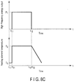
- control section 14 may supply energy to the first and second electrode portions 134 and 174 simultaneously to supply energy to the heating element 126, as shown in FIG. 8C .
- control section 14 may supply energy to the heating element 126 after initiation of energy supply to the first and second electrode portions 134 and 174 as shown in FIGS. 6 , 8A , and 8B .
- the present embodiment is a modification of the first embodiment, in which, to omit detailed explanations, the same symbols as those in the first embodiment will be applied whenever possible to the same members or the members with the same functions as those explained in the first embodiment.
- the high frequency energy source and the heat energy source sequentially output energy in order as shown in the graph of FIG. 6 and the flowchart of FIG. 7 . It is also preferable that treatment is performed by outputting energy to living tissue as shown in FIGS. 8A to 8C .
- a projected surf ace 136a is preferably covered with a coating 136b which has electrical insulation properties and heat resistance.
- the coating 136b is consecutively formed from the proximal end to the distal end along the longitudinal direction ⁇ .
- the coating 136b having electrical insulation properties blocks an energy flow from a high frequency energy source 184 between the projected surface 136a of a blade 136 and second electrode portions 174 .
- a current is applied to living tissue mainly between the first electrode portions 134 and the second electrode portions 174.
- the living tissue between first holding surfaces 132 and second holding surfaces 172 is sealed. Part of the living tissue which is brought into contact with the coating 136b of the blade 136 may be sealed by the effects of Joule heat.
- the coating 136b gives electrical insulation properties to the projected surface 136a. However, it is more preferable that the coating 136b has a function of preventing adhesion of living tissue.
- This embodiment is a modification of the first and second embodiments.
- same members or the members having the same functions as those of the members of the first and second embodiments are identified by the same reference symbols as those used for those embodiments whenever possible.
- the projected surface 136a of the blade 136 has an obtuse shape.
- the cross sectional surface of a projected surface 136a of a blade 136 is preferably formed as a V-shape. That is, the projected surface 136a of the blade 136 has an edge 13 6c from the proximal end to the distal end along the longitudinal direction ⁇ .
- first holding surfaces 132 are preferably formed as a plane or essentially plane consecutive relative to the projected surface 136a.
- a receiving portion 166 is formed between the pair of holding bodies, as shown in FIGS. 5A and 5B , similar to the first embodiment.
- a receiving portion 167 formed of an elastic body that is elastically deformable and has electrical insulation properties and heat resistance, such as a resin material or rubber material is fixed between a pair of second electrode portions 174, instead of the receiving portion 166 which has a concave shape. That is, the second electrode portions 174 are formed to enclose the perimeter of the receiving portion 167 .
- the receiving portion 167 may be a block shape or a film shape if it has a surface 167a that receives the edge 136c.
- the distance between the holding surfaces 132 and 172 decreases, and a pressure applied to living tissue increases as the holding surfaces 132 and 172 become closer to the blade 136 in the width direction ⁇ .
- the living tissue held between the holding surfaces 132 and 172 becomes easier to be sealed as the living tissue comes closer to the projected surface 136a of the blade 136.
- the projected surface 136a of the blade 136 has a sharp edge 136c in comparison with the obtuse shape as explained in the first embodiment.
- an area which applies pressure to living tissue can be decreased so that the pressure can be focused on the decreased area.
- the speed of incision at a position of living tissue which is pressed by the edge 136c can be increased in comparison to when using the obtuse projected surface 136a, as explained in the first embodiment.
- this embodiment is a modification of the second embodiment, and the aforementioned coating 136b is preferably provided to the edge 136c. Although it depends on the area of the coating 136b, it is possible to prevent a concentration of current density to the edge 136c when sealing the living tissue by using high frequency energy. Accordingly, it is possible to seal living tissue brought into contact between the holding surfaces 132 and 172 by generating Joule heat.
- This embodiment is a modification of the first to third embodiments.
- the same members or the members having the same functions as those of the members of the first to third embodiments are identified by the same reference symbols as those used for those embodiments whenever possible.
- a first holding section 124 is formed as a two-part or three-part body.
- An electrode portions 134 and a blade 136 of the first holding section 124 is separately formed, instead of integrally formed.
- the electrode portions 134 have a ring shape, namely, may be formed as a one-part body, or as a two-part body, if the same potential is reliably maintained.
- the electrode portions 134 may be formed of copper alloy, and the blade 136 may be formed of nickel alloy. That is, it is preferable that the electrode portions 134 and the blade 136 are formed of materials that are mutually different in thermal conductivity or conductivity.
- An insulation plate 142 that has electrical insulation properties and heat resistance is disposed between the electrode portions 134 and blade 136. Accordingly, the blade 136 is electrically separated from the electrode portions 134.
- the blade 136 is preferably not electrically connected to a high frequency energy source 184. In this case, even if the high frequency energy source 184 outputs energy, Joule heat is not generated to living tissue between the blade 136 and second electrode portions 174. Thus, a part of the living tissue between the first and second holding surfaces 132 and 172 is sealed by the output of energy from the high frequency energy source 184.
- the heating element 126 is in contact not only with the blade 136, but also with the electrode portions 134. In this case, heat energy can be transmitted to living tissue through the electrode portions 134. Accordingly, while living tissue between the holding surfaces 132 and 172 is dehydrated, the living tissue can be incised by the projected surface 136a which applies higher pressure in comparison with the other portions.
- This embodiment is a modification of the first to fourth embodiments.
- the same members or the members having the same functions as those of the members of the first to fourth embodiments are identified by the same reference symbols as those used for those embodiments whenever possible.
- a main body 122 includes a plurality of recesses 128a.
- the recesses 128a respectively include electrode portions 134, a blade 136, and a heating element 126 inside thereof.
- An inclined surface 128b formed as a part of the main body 122 is formed between a projected surface 136a of the blade 136 and each of a pair of holding surfaces 132 formed in the electrode portions 134.
- the inclined surface 128b which is a part of the main body 122 having electrical insulation properties and heat resistance, functions as a holding surface.
- the inclined surface 128b which has electrical insulation properties and heat resistance, is a part of the holding surfaces 132.
- the heating element 126 transmits heat energy relative to the blade 136 in the width direction, and transmits heat to the projected surface 136a of the blade 136.
- Part of a main body 162 between second holding surfaces 172 is formed as a flat surface in this embodiment. Even in this structure, living tissue can be sealed and incised, as explained in the first embodiment.
- a coating 13 6b is formed on the projected surface 13 6a of the blade 136.
- This embodiment is a modification of the first to fifth embodiments.
- the same members or the members having the same functions as those of the members of the first to fifth embodiments are identified by the same reference symbols as those used for those embodiments whenever possible.
- a blade 136 is not provided to a first treatment piece 102, and a blade 236 is provided to a second treatment piece 104.
- the blade 236 is preferably formed of a material which has electrical insulation properties and heat resistance, such as PTFE, for example.
- the blade 236 may be formed integrally with the main body 162, or independently from the main body 162.
- a receiving portion (plane portion) 133 which is a plane or a smooth curved surface, is formed between a pair of holding surfaces 132 of the first treatment piece 102.
- the receiving portion 133 is formed of a material which has good conductivity and good thermal conductivity, such as copper alloy material, for example.
- the receiving portion 133 is preferably formed integrally with the first holding surfaces 132. It is also preferable that the receiving portion 133 is coated, in a similar manner by a coating 136b as explained in the second embodiment.
- the blade 236 of the second treatment piece 104 has a projected surface 236a that is formed between a pair of electrode portions 174 to project toward the receiving portion 133.
- the projected surface 236a is formed from the proximal end to the distal end along the longitudinal direction ⁇ of the main body 162 of the second holding body 164.
- the projected surface 236a may be an obtuse shape like the projected surface 136a explained in the first embodiment, or have an edge like the projected surface 136a explained in the third embodiment.
- the living tissue can be further dehydrated by the applied pressure and heat transmitted from the receiving portion 133. Accordingly, the projected surface 236a of the blade 236 applies pressure to the living tissue held between the first and second holding surfaces 132 and 172, and incises the living tissue.
Applications Claiming Priority (2)
| Application Number | Priority Date | Filing Date | Title |
|---|---|---|---|
| JP2014233825 | 2014-11-18 | ||
| PCT/JP2015/079961 WO2016080147A1 (fr) | 2014-11-18 | 2015-10-23 | Outil de traitement et système de traitement |
Publications (3)
| Publication Number | Publication Date |
|---|---|
| EP3222239A1 true EP3222239A1 (fr) | 2017-09-27 |
| EP3222239A4 EP3222239A4 (fr) | 2018-08-08 |
| EP3222239B1 EP3222239B1 (fr) | 2022-04-20 |
Family
ID=56013704
Family Applications (1)
| Application Number | Title | Priority Date | Filing Date |
|---|---|---|---|
| EP15861368.7A Active EP3222239B1 (fr) | 2014-11-18 | 2015-10-23 | Outil de traitement et système de traitement |
Country Status (5)
| Country | Link |
|---|---|
| US (1) | US20170245923A1 (fr) |
| EP (1) | EP3222239B1 (fr) |
| JP (2) | JP6224840B2 (fr) |
| CN (1) | CN107072709B (fr) |
| WO (1) | WO2016080147A1 (fr) |
Cited By (2)
| Publication number | Priority date | Publication date | Assignee | Title |
|---|---|---|---|---|
| WO2022248958A1 (fr) * | 2021-05-27 | 2022-12-01 | Covidien Lp | Dissection ouverte utilisant un instrument d'étanchéité |
| WO2022248955A1 (fr) * | 2021-05-27 | 2022-12-01 | Covidien Lp | Système et procédé de découpe de tissu à l'aide d'un instrument d'étanchéité de tissu électrochirurgical |
Families Citing this family (8)
| Publication number | Priority date | Publication date | Assignee | Title |
|---|---|---|---|---|
| DE102016114537A1 (de) * | 2016-08-05 | 2018-02-08 | Aesculap Ag | Verfahren und Vorrichtung zur Steuerung der Energiezufuhr zu einem medizinischen Instrument |
| CN109922749B (zh) | 2016-11-09 | 2021-10-12 | 奥林巴斯株式会社 | 医疗设备 |
| WO2018173151A1 (fr) * | 2017-03-22 | 2018-09-27 | オリンパス株式会社 | Système de traitement |
| WO2018193492A1 (fr) * | 2017-04-17 | 2018-10-25 | オリンパス株式会社 | Dispositif de traitement |
| WO2018198339A1 (fr) | 2017-04-28 | 2018-11-01 | オリンパス株式会社 | Outil de traitement énergétique et système de traitement |
| WO2018220736A1 (fr) * | 2017-05-31 | 2018-12-06 | オリンパス株式会社 | Instrument de traitement |
| WO2019229860A1 (fr) * | 2018-05-29 | 2019-12-05 | オリンパス株式会社 | Outil de traitement |
| WO2020008570A1 (fr) * | 2018-07-04 | 2020-01-09 | オリンパス株式会社 | Outil de traitement médical |
Family Cites Families (26)
| Publication number | Priority date | Publication date | Assignee | Title |
|---|---|---|---|---|
| GB9905210D0 (en) * | 1999-03-05 | 1999-04-28 | Gyrus Medical Ltd | Electrosurgical system |
| JP4315557B2 (ja) * | 2000-01-12 | 2009-08-19 | オリンパス株式会社 | 医療用処置具 |
| JP2003116871A (ja) * | 2001-10-16 | 2003-04-22 | Olympus Optical Co Ltd | 処置具 |
| JP2003175053A (ja) * | 2001-12-11 | 2003-06-24 | Olympus Optical Co Ltd | 高周波処置具 |
| US20030114851A1 (en) * | 2001-12-13 | 2003-06-19 | Csaba Truckai | Electrosurgical jaws for controlled application of clamping pressure |
| US6602252B2 (en) * | 2002-01-03 | 2003-08-05 | Starion Instruments Corporation | Combined dissecting, cauterizing, and stapling device |
| US7931649B2 (en) * | 2002-10-04 | 2011-04-26 | Tyco Healthcare Group Lp | Vessel sealing instrument with electrical cutting mechanism |
| JP2004188012A (ja) * | 2002-12-12 | 2004-07-08 | Olympus Corp | 医療器械 |
| DE102004031141A1 (de) * | 2004-06-28 | 2006-01-26 | Erbe Elektromedizin Gmbh | Elektrochirurgisches Instrument |
| DE102004055671B4 (de) * | 2004-08-11 | 2010-01-07 | Erbe Elektromedizin Gmbh | Elektrochirurgisches Instrument |
| JP4734058B2 (ja) * | 2005-07-29 | 2011-07-27 | オリンパスメディカルシステムズ株式会社 | 医療用処置装置 |
| JP4157574B2 (ja) * | 2006-07-04 | 2008-10-01 | オリンパスメディカルシステムズ株式会社 | 外科用処置具 |
| US7717914B2 (en) * | 2006-07-11 | 2010-05-18 | Olympus Medical Systems Corporation | Treatment device |
| US20080015575A1 (en) * | 2006-07-14 | 2008-01-17 | Sherwood Services Ag | Vessel sealing instrument with pre-heated electrodes |
| EP2157927A4 (fr) * | 2007-05-22 | 2011-06-22 | David A Schechter | Appareil pour l'attache et le renforcement de tissu, appareil pour le renforcement de tissu, procédés d'attache et de renforcement de tissu et procédés de renforcement de tissu |
| US20090182330A1 (en) * | 2008-01-11 | 2009-07-16 | Live Tissue Connect, Inc. | Bipolar modular foreceps RF voltage conductor assembly |
| EP2285305A2 (fr) * | 2008-05-27 | 2011-02-23 | Maquet Cardiovascular LLC | Instrument et procédé chirurgical |
| US8512336B2 (en) * | 2010-07-08 | 2013-08-20 | Covidien Lp | Optimal geometries for creating current densities in a bipolar electrode configuration |
| US8840609B2 (en) * | 2010-07-23 | 2014-09-23 | Conmed Corporation | Tissue fusion system and method of performing a functional verification test |
| US8663222B2 (en) * | 2010-09-07 | 2014-03-04 | Covidien Lp | Dynamic and static bipolar electrical sealing and cutting device |
| WO2013040255A2 (fr) * | 2011-09-13 | 2013-03-21 | Domain Surgical, Inc. | Instrument de découpe et/ou de scellage |
| WO2013088891A1 (fr) * | 2011-12-12 | 2013-06-20 | オリンパスメディカルシステムズ株式会社 | Système de traitement, et procédé de commande de système de traitement |
| CN104334105B (zh) * | 2012-06-01 | 2017-02-22 | 奥林巴斯株式会社 | 使用能量的处理器具 |
| WO2013180293A1 (fr) * | 2012-06-01 | 2013-12-05 | オリンパスメディカルシステムズ株式会社 | Outil de traitement utilisant de l'énergie |
| US20140148801A1 (en) * | 2012-11-26 | 2014-05-29 | Medtronic Advanced Energy Llc | Surgical device |
| WO2014141530A1 (fr) * | 2013-03-12 | 2014-09-18 | オリンパスメディカルシステムズ株式会社 | Dispositif de traitement et procédé de traitement |
-
2015
- 2015-10-23 CN CN201580056432.7A patent/CN107072709B/zh active Active
- 2015-10-23 EP EP15861368.7A patent/EP3222239B1/fr active Active
- 2015-10-23 WO PCT/JP2015/079961 patent/WO2016080147A1/fr active Application Filing
- 2015-10-23 JP JP2016537575A patent/JP6224840B2/ja active Active
-
2017
- 2017-05-17 US US15/597,692 patent/US20170245923A1/en not_active Abandoned
- 2017-10-05 JP JP2017195429A patent/JP6461275B2/ja active Active
Cited By (2)
| Publication number | Priority date | Publication date | Assignee | Title |
|---|---|---|---|---|
| WO2022248958A1 (fr) * | 2021-05-27 | 2022-12-01 | Covidien Lp | Dissection ouverte utilisant un instrument d'étanchéité |
| WO2022248955A1 (fr) * | 2021-05-27 | 2022-12-01 | Covidien Lp | Système et procédé de découpe de tissu à l'aide d'un instrument d'étanchéité de tissu électrochirurgical |
Also Published As
| Publication number | Publication date |
|---|---|
| JPWO2016080147A1 (ja) | 2017-04-27 |
| JP6224840B2 (ja) | 2017-11-01 |
| JP2017225882A (ja) | 2017-12-28 |
| CN107072709A (zh) | 2017-08-18 |
| CN107072709B (zh) | 2020-02-28 |
| EP3222239B1 (fr) | 2022-04-20 |
| EP3222239A4 (fr) | 2018-08-08 |
| US20170245923A1 (en) | 2017-08-31 |
| JP6461275B2 (ja) | 2019-01-30 |
| WO2016080147A1 (fr) | 2016-05-26 |
Similar Documents
| Publication | Publication Date | Title |
|---|---|---|
| EP3222239B1 (fr) | Outil de traitement et système de traitement | |
| US10342602B2 (en) | Managing tissue treatment | |
| US20180161062A1 (en) | Treatment tool | |
| US10194972B2 (en) | Managing tissue treatment | |
| US20190008573A1 (en) | Treatment system, and treatment method for living tissue using energy | |
| JP5116383B2 (ja) | 予熱電極を有する脈管密封器具 | |
| US7329257B2 (en) | Medical treatment instrument | |
| JP4981505B2 (ja) | 処置装置 | |
| JP4459814B2 (ja) | 組織をシールし、そして切断するための電極アセンブリおよび組織をシールし、そして切断することを実施するための方法 | |
| US9492221B2 (en) | Dissection scissors on surgical device | |
| US20160270840A1 (en) | Managing tissue treatment | |
| US20120330308A1 (en) | Forceps | |
| EP2939616A1 (fr) | Instruments électrochirurgicaux comprenant un ensemble effecteur terminal permettant d'exercer une action de coupe mécanique sur le tissu | |
| JP2006501939A5 (fr) | ||
| JP2001198137A (ja) | 凝固切開システム | |
| JP5814685B2 (ja) | 治療用処置装置 | |
| JP6125117B2 (ja) | 医療機器 | |
| US20150313628A1 (en) | Electrosurgical instruments including end-effector assembly configured to provide mechanical cutting action on tissue | |
| US9526566B1 (en) | Electrosurgical devices with phase change materials | |
| US10531909B2 (en) | Treatment instrument | |
| CN109475380B (zh) | 处置器具 | |
| JP2003093402A (ja) | 手術器械 | |
| WO2018189884A1 (fr) | Outil de traitement | |
| JP2003061976A (ja) | 手術器械 |
Legal Events
| Date | Code | Title | Description |
|---|---|---|---|
| STAA | Information on the status of an ep patent application or granted ep patent |
Free format text: STATUS: THE INTERNATIONAL PUBLICATION HAS BEEN MADE |
|
| PUAI | Public reference made under article 153(3) epc to a published international application that has entered the european phase |
Free format text: ORIGINAL CODE: 0009012 |
|
| STAA | Information on the status of an ep patent application or granted ep patent |
Free format text: STATUS: REQUEST FOR EXAMINATION WAS MADE |
|
| 17P | Request for examination filed |
Effective date: 20170609 |
|
| AK | Designated contracting states |
Kind code of ref document: A1 Designated state(s): AL AT BE BG CH CY CZ DE DK EE ES FI FR GB GR HR HU IE IS IT LI LT LU LV MC MK MT NL NO PL PT RO RS SE SI SK SM TR |
|
| AX | Request for extension of the european patent |
Extension state: BA ME |
|
| DAV | Request for validation of the european patent (deleted) | ||
| DAX | Request for extension of the european patent (deleted) | ||
| A4 | Supplementary search report drawn up and despatched |
Effective date: 20180705 |
|
| RIC1 | Information provided on ipc code assigned before grant |
Ipc: A61B 18/12 20060101AFI20180629BHEP |
|
| GRAP | Despatch of communication of intention to grant a patent |
Free format text: ORIGINAL CODE: EPIDOSNIGR1 |
|
| STAA | Information on the status of an ep patent application or granted ep patent |
Free format text: STATUS: GRANT OF PATENT IS INTENDED |
|
| INTG | Intention to grant announced |
Effective date: 20220105 |
|
| GRAS | Grant fee paid |
Free format text: ORIGINAL CODE: EPIDOSNIGR3 |
|
| GRAA | (expected) grant |
Free format text: ORIGINAL CODE: 0009210 |
|
| STAA | Information on the status of an ep patent application or granted ep patent |
Free format text: STATUS: THE PATENT HAS BEEN GRANTED |
|
| AK | Designated contracting states |
Kind code of ref document: B1 Designated state(s): AL AT BE BG CH CY CZ DE DK EE ES FI FR GB GR HR HU IE IS IT LI LT LU LV MC MK MT NL NO PL PT RO RS SE SI SK SM TR |
|
| REG | Reference to a national code |
Ref country code: GB Ref legal event code: FG4D |
|
| REG | Reference to a national code |
Ref country code: CH Ref legal event code: EP |
|
| REG | Reference to a national code |
Ref country code: IE Ref legal event code: FG4D |
|
| REG | Reference to a national code |
Ref country code: DE Ref legal event code: R096 Ref document number: 602015078428 Country of ref document: DE |
|
| REG | Reference to a national code |
Ref country code: AT Ref legal event code: REF Ref document number: 1484575 Country of ref document: AT Kind code of ref document: T Effective date: 20220515 |
|
| REG | Reference to a national code |
Ref country code: LT Ref legal event code: MG9D |
|
| REG | Reference to a national code |
Ref country code: NL Ref legal event code: MP Effective date: 20220420 |
|
| REG | Reference to a national code |
Ref country code: AT Ref legal event code: MK05 Ref document number: 1484575 Country of ref document: AT Kind code of ref document: T Effective date: 20220420 |
|
| PG25 | Lapsed in a contracting state [announced via postgrant information from national office to epo] |
Ref country code: NL Free format text: LAPSE BECAUSE OF FAILURE TO SUBMIT A TRANSLATION OF THE DESCRIPTION OR TO PAY THE FEE WITHIN THE PRESCRIBED TIME-LIMIT Effective date: 20220420 |
|
| PG25 | Lapsed in a contracting state [announced via postgrant information from national office to epo] |
Ref country code: SE Free format text: LAPSE BECAUSE OF FAILURE TO SUBMIT A TRANSLATION OF THE DESCRIPTION OR TO PAY THE FEE WITHIN THE PRESCRIBED TIME-LIMIT Effective date: 20220420 Ref country code: PT Free format text: LAPSE BECAUSE OF FAILURE TO SUBMIT A TRANSLATION OF THE DESCRIPTION OR TO PAY THE FEE WITHIN THE PRESCRIBED TIME-LIMIT Effective date: 20220822 Ref country code: NO Free format text: LAPSE BECAUSE OF FAILURE TO SUBMIT A TRANSLATION OF THE DESCRIPTION OR TO PAY THE FEE WITHIN THE PRESCRIBED TIME-LIMIT Effective date: 20220720 Ref country code: LT Free format text: LAPSE BECAUSE OF FAILURE TO SUBMIT A TRANSLATION OF THE DESCRIPTION OR TO PAY THE FEE WITHIN THE PRESCRIBED TIME-LIMIT Effective date: 20220420 Ref country code: HR Free format text: LAPSE BECAUSE OF FAILURE TO SUBMIT A TRANSLATION OF THE DESCRIPTION OR TO PAY THE FEE WITHIN THE PRESCRIBED TIME-LIMIT Effective date: 20220420 Ref country code: GR Free format text: LAPSE BECAUSE OF FAILURE TO SUBMIT A TRANSLATION OF THE DESCRIPTION OR TO PAY THE FEE WITHIN THE PRESCRIBED TIME-LIMIT Effective date: 20220721 Ref country code: FI Free format text: LAPSE BECAUSE OF FAILURE TO SUBMIT A TRANSLATION OF THE DESCRIPTION OR TO PAY THE FEE WITHIN THE PRESCRIBED TIME-LIMIT Effective date: 20220420 Ref country code: ES Free format text: LAPSE BECAUSE OF FAILURE TO SUBMIT A TRANSLATION OF THE DESCRIPTION OR TO PAY THE FEE WITHIN THE PRESCRIBED TIME-LIMIT Effective date: 20220420 Ref country code: BG Free format text: LAPSE BECAUSE OF FAILURE TO SUBMIT A TRANSLATION OF THE DESCRIPTION OR TO PAY THE FEE WITHIN THE PRESCRIBED TIME-LIMIT Effective date: 20220720 Ref country code: AT Free format text: LAPSE BECAUSE OF FAILURE TO SUBMIT A TRANSLATION OF THE DESCRIPTION OR TO PAY THE FEE WITHIN THE PRESCRIBED TIME-LIMIT Effective date: 20220420 |
|
| PG25 | Lapsed in a contracting state [announced via postgrant information from national office to epo] |
Ref country code: RS Free format text: LAPSE BECAUSE OF FAILURE TO SUBMIT A TRANSLATION OF THE DESCRIPTION OR TO PAY THE FEE WITHIN THE PRESCRIBED TIME-LIMIT Effective date: 20220420 Ref country code: PL Free format text: LAPSE BECAUSE OF FAILURE TO SUBMIT A TRANSLATION OF THE DESCRIPTION OR TO PAY THE FEE WITHIN THE PRESCRIBED TIME-LIMIT Effective date: 20220420 Ref country code: LV Free format text: LAPSE BECAUSE OF FAILURE TO SUBMIT A TRANSLATION OF THE DESCRIPTION OR TO PAY THE FEE WITHIN THE PRESCRIBED TIME-LIMIT Effective date: 20220420 Ref country code: IS Free format text: LAPSE BECAUSE OF FAILURE TO SUBMIT A TRANSLATION OF THE DESCRIPTION OR TO PAY THE FEE WITHIN THE PRESCRIBED TIME-LIMIT Effective date: 20220820 |
|
| REG | Reference to a national code |
Ref country code: DE Ref legal event code: R097 Ref document number: 602015078428 Country of ref document: DE |
|
| PG25 | Lapsed in a contracting state [announced via postgrant information from national office to epo] |
Ref country code: SM Free format text: LAPSE BECAUSE OF FAILURE TO SUBMIT A TRANSLATION OF THE DESCRIPTION OR TO PAY THE FEE WITHIN THE PRESCRIBED TIME-LIMIT Effective date: 20220420 Ref country code: SK Free format text: LAPSE BECAUSE OF FAILURE TO SUBMIT A TRANSLATION OF THE DESCRIPTION OR TO PAY THE FEE WITHIN THE PRESCRIBED TIME-LIMIT Effective date: 20220420 Ref country code: RO Free format text: LAPSE BECAUSE OF FAILURE TO SUBMIT A TRANSLATION OF THE DESCRIPTION OR TO PAY THE FEE WITHIN THE PRESCRIBED TIME-LIMIT Effective date: 20220420 Ref country code: EE Free format text: LAPSE BECAUSE OF FAILURE TO SUBMIT A TRANSLATION OF THE DESCRIPTION OR TO PAY THE FEE WITHIN THE PRESCRIBED TIME-LIMIT Effective date: 20220420 Ref country code: DK Free format text: LAPSE BECAUSE OF FAILURE TO SUBMIT A TRANSLATION OF THE DESCRIPTION OR TO PAY THE FEE WITHIN THE PRESCRIBED TIME-LIMIT Effective date: 20220420 Ref country code: CZ Free format text: LAPSE BECAUSE OF FAILURE TO SUBMIT A TRANSLATION OF THE DESCRIPTION OR TO PAY THE FEE WITHIN THE PRESCRIBED TIME-LIMIT Effective date: 20220420 |
|
| PLBE | No opposition filed within time limit |
Free format text: ORIGINAL CODE: 0009261 |
|
| STAA | Information on the status of an ep patent application or granted ep patent |
Free format text: STATUS: NO OPPOSITION FILED WITHIN TIME LIMIT |
|
| 26N | No opposition filed |
Effective date: 20230123 |
|
| PG25 | Lapsed in a contracting state [announced via postgrant information from national office to epo] |
Ref country code: AL Free format text: LAPSE BECAUSE OF FAILURE TO SUBMIT A TRANSLATION OF THE DESCRIPTION OR TO PAY THE FEE WITHIN THE PRESCRIBED TIME-LIMIT Effective date: 20220420 |
|
| PG25 | Lapsed in a contracting state [announced via postgrant information from national office to epo] |
Ref country code: SI Free format text: LAPSE BECAUSE OF FAILURE TO SUBMIT A TRANSLATION OF THE DESCRIPTION OR TO PAY THE FEE WITHIN THE PRESCRIBED TIME-LIMIT Effective date: 20220420 Ref country code: MC Free format text: LAPSE BECAUSE OF FAILURE TO SUBMIT A TRANSLATION OF THE DESCRIPTION OR TO PAY THE FEE WITHIN THE PRESCRIBED TIME-LIMIT Effective date: 20220420 |
|
| REG | Reference to a national code |
Ref country code: CH Ref legal event code: PL |
|
| REG | Reference to a national code |
Ref country code: BE Ref legal event code: MM Effective date: 20221031 |
|
| GBPC | Gb: european patent ceased through non-payment of renewal fee |
Effective date: 20221023 |
|
| PG25 | Lapsed in a contracting state [announced via postgrant information from national office to epo] |
Ref country code: LU Free format text: LAPSE BECAUSE OF NON-PAYMENT OF DUE FEES Effective date: 20221023 |
|
| P01 | Opt-out of the competence of the unified patent court (upc) registered |
Effective date: 20230528 |
|
| PG25 | Lapsed in a contracting state [announced via postgrant information from national office to epo] |
Ref country code: LI Free format text: LAPSE BECAUSE OF NON-PAYMENT OF DUE FEES Effective date: 20221031 Ref country code: FR Free format text: LAPSE BECAUSE OF NON-PAYMENT OF DUE FEES Effective date: 20221031 Ref country code: CH Free format text: LAPSE BECAUSE OF NON-PAYMENT OF DUE FEES Effective date: 20221031 |
|
| PG25 | Lapsed in a contracting state [announced via postgrant information from national office to epo] |
Ref country code: BE Free format text: LAPSE BECAUSE OF NON-PAYMENT OF DUE FEES Effective date: 20221031 |
|
| PG25 | Lapsed in a contracting state [announced via postgrant information from national office to epo] |
Ref country code: IE Free format text: LAPSE BECAUSE OF NON-PAYMENT OF DUE FEES Effective date: 20221023 Ref country code: GB Free format text: LAPSE BECAUSE OF NON-PAYMENT OF DUE FEES Effective date: 20221023 |
|
| PG25 | Lapsed in a contracting state [announced via postgrant information from national office to epo] |
Ref country code: IT Free format text: LAPSE BECAUSE OF FAILURE TO SUBMIT A TRANSLATION OF THE DESCRIPTION OR TO PAY THE FEE WITHIN THE PRESCRIBED TIME-LIMIT Effective date: 20220420 |
|
| PGFP | Annual fee paid to national office [announced via postgrant information from national office to epo] |
Ref country code: DE Payment date: 20231020 Year of fee payment: 9 |
|
| PG25 | Lapsed in a contracting state [announced via postgrant information from national office to epo] |
Ref country code: HU Free format text: LAPSE BECAUSE OF FAILURE TO SUBMIT A TRANSLATION OF THE DESCRIPTION OR TO PAY THE FEE WITHIN THE PRESCRIBED TIME-LIMIT; INVALID AB INITIO Effective date: 20151023 |