EP3221929B1 - Magnetische verbindungsvorrichtung - Google Patents
Magnetische verbindungsvorrichtung Download PDFInfo
- Publication number
- EP3221929B1 EP3221929B1 EP15791307.0A EP15791307A EP3221929B1 EP 3221929 B1 EP3221929 B1 EP 3221929B1 EP 15791307 A EP15791307 A EP 15791307A EP 3221929 B1 EP3221929 B1 EP 3221929B1
- Authority
- EP
- European Patent Office
- Prior art keywords
- magnetic
- connection
- pair
- connections
- another
- Prior art date
- Legal status (The legal status is an assumption and is not a legal conclusion. Google has not performed a legal analysis and makes no representation as to the accuracy of the status listed.)
- Active
Links
Images




Classifications
-
- H—ELECTRICITY
- H01—ELECTRIC ELEMENTS
- H01R—ELECTRICALLY-CONDUCTIVE CONNECTIONS; STRUCTURAL ASSOCIATIONS OF A PLURALITY OF MUTUALLY-INSULATED ELECTRICAL CONNECTING ELEMENTS; COUPLING DEVICES; CURRENT COLLECTORS
- H01R13/00—Details of coupling devices of the kinds covered by groups H01R12/70 or H01R24/00 - H01R33/00
- H01R13/62—Means for facilitating engagement or disengagement of coupling parts or for holding them in engagement
- H01R13/6205—Two-part coupling devices held in engagement by a magnet
-
- G—PHYSICS
- G06—COMPUTING OR CALCULATING; COUNTING
- G06F—ELECTRIC DIGITAL DATA PROCESSING
- G06F1/00—Details not covered by groups G06F3/00 - G06F13/00 and G06F21/00
- G06F1/16—Constructional details or arrangements
- G06F1/1613—Constructional details or arrangements for portable computers
- G06F1/1632—External expansion units, e.g. docking stations
-
- G—PHYSICS
- G06—COMPUTING OR CALCULATING; COUNTING
- G06F—ELECTRIC DIGITAL DATA PROCESSING
- G06F1/00—Details not covered by groups G06F3/00 - G06F13/00 and G06F21/00
- G06F1/16—Constructional details or arrangements
- G06F1/1613—Constructional details or arrangements for portable computers
- G06F1/1633—Constructional details or arrangements of portable computers not specific to the type of enclosures covered by groups G06F1/1615 - G06F1/1626
- G06F1/1675—Miscellaneous details related to the relative movement between the different enclosures or enclosure parts
- G06F1/1683—Miscellaneous details related to the relative movement between the different enclosures or enclosure parts for the transmission of signal or power between the different housings, e.g. details of wired or wireless communication, passage of cabling
-
- H—ELECTRICITY
- H01—ELECTRIC ELEMENTS
- H01R—ELECTRICALLY-CONDUCTIVE CONNECTIONS; STRUCTURAL ASSOCIATIONS OF A PLURALITY OF MUTUALLY-INSULATED ELECTRICAL CONNECTING ELEMENTS; COUPLING DEVICES; CURRENT COLLECTORS
- H01R35/00—Flexible or turnable line connectors, i.e. the rotation angle being limited
- H01R35/04—Turnable line connectors with limited rotation angle with frictional contact members
-
- H—ELECTRICITY
- H04—ELECTRIC COMMUNICATION TECHNIQUE
- H04M—TELEPHONIC COMMUNICATION
- H04M1/00—Substation equipment, e.g. for use by subscribers
- H04M1/02—Constructional features of telephone sets
- H04M1/0202—Portable telephone sets, e.g. cordless phones, mobile phones or bar type handsets
- H04M1/0206—Portable telephones comprising a plurality of mechanically joined movable body parts, e.g. hinged housings
- H04M1/0208—Portable telephones comprising a plurality of mechanically joined movable body parts, e.g. hinged housings characterized by the relative motions of the body parts
- H04M1/0214—Foldable telephones, i.e. with body parts pivoting to an open position around an axis parallel to the plane they define in closed position
- H04M1/0216—Foldable in one direction, i.e. using a one degree of freedom hinge
-
- G—PHYSICS
- G06—COMPUTING OR CALCULATING; COUNTING
- G06F—ELECTRIC DIGITAL DATA PROCESSING
- G06F1/00—Details not covered by groups G06F3/00 - G06F13/00 and G06F21/00
- G06F1/16—Constructional details or arrangements
- G06F1/1613—Constructional details or arrangements for portable computers
- G06F1/1633—Constructional details or arrangements of portable computers not specific to the type of enclosures covered by groups G06F1/1615 - G06F1/1626
- G06F1/1675—Miscellaneous details related to the relative movement between the different enclosures or enclosure parts
- G06F1/1681—Details related solely to hinges
-
- H—ELECTRICITY
- H01—ELECTRIC ELEMENTS
- H01R—ELECTRICALLY-CONDUCTIVE CONNECTIONS; STRUCTURAL ASSOCIATIONS OF A PLURALITY OF MUTUALLY-INSULATED ELECTRICAL CONNECTING ELEMENTS; COUPLING DEVICES; CURRENT COLLECTORS
- H01R2201/00—Connectors or connections adapted for particular applications
- H01R2201/16—Connectors or connections adapted for particular applications for telephony
Definitions
- the invention relates to a magnetic connecting device for connecting two units.
- such a magnetic connection device can be used to establish any conceivable connection and is therefore particularly suitable for establishing an electrical connection.
- a device for establishing a connection between an electrical device and a cable that can be connected to the device or a further electrical device is presented.
- the device is to comprise an adapter with two adapter parts with magnetic elements, whereby a connection of the electrical device with another electrical device, eg. B. a charger, headphones, a microphone or a headset is created.
- the connection should take place in a first step by a rough guide over at least one projection and an annular recess, for which a correspondingly large play is provided.
- the two adapter parts are precisely positioned and centered with respect to one another using the magnetic forces of the magnetic elements.
- a major advantage here is that the user only has to roughly approach the two parts and does not have to pay attention to correct contacting and assignment of contacts. This means that connections can be made quickly and easily even in hard-to-reach places. At the same time, it is ensured that in the event of excessive load on the connection, by which it z. B. could damage components, the connection comes loose as soon as the magnetic holding forces are overcome by a higher force from the outside.
- the magnetic connection device specifies the alignment of the plug-in elements or connecting links to one another.
- twisting of the electrical devices relative to one another is not tolerated and would inevitably lead to the opening of the magnetic and thus also the electrical connection.
- the flexibility of a cable connection, for example is consequently severely restricted by the precise specification of the approach angle. If two electrical devices are to be connected directly to one another, such as mobile electrical devices, docking stations or input devices, the fixed predetermined orientation can in particular significantly reduce user comfort.
- US Pat WO 2010/088695 A1 a device with a module having a recess.
- a magnetic assembly is movable in the recess and a flexible circuit cooperates with the module to hold the magnetic assembly in the recess.
- the movement of the magnetic assembly is caused by magnetic attraction between the magnetic assembly and an external magnetic assembly.
- the flexible circuit contains a resilient contact which can change its shape through the movement of the magnetic arrangement.
- the US 2014/273546 A1 discloses an electrical connection system, particularly a magnetic connection system, for electronic devices.
- the WO 2014/120966 A1 an electrical contact and a connector technology.
- the US 6,272,324 B1 discloses portable radio communication devices having a hinged cover.
- the US 2013/170126 A1 relates to a mobile device with two connectable housing parts to form different variants for using the device. It also affects the U.S. 4,865,553 A an electrical connector for use with various electronic devices.
- the WO 03/100792 A2 an electrical connector for use in the hinge of an electronic device.
- the present invention is based on the object of creating an advantageous articulated or rotatable connection between two units.
- a first unit is assigned at least one first connecting member and a second unit is assigned at least one second connecting member, a first connecting member and a second connecting member forming a connecting pair, the connecting members of a connecting pair each having a plurality of contacts , wherein the connecting members of a connecting pair are arranged axially parallel to one another and magnetically contact one another and wherein the connecting members of a connecting pair can be rotated relative to one another in the contacted state.
- the first unit and the second unit are preferably electrical or electronic units.
- the plurality of contacts are preferably electrical contacts which are provided for the transmission of data and / or signals and / or for conducting current.
- the links of a link pair are magnetically connected to one another. In addition to the magnetic connection, a rough mechanical guide is provided in order to simplify the establishment of the contact between the connecting members and thus between the units.
- a mobile phone, a tablet or an electronic unit can preferably also be connected to a shell, a docking station, a housing, a cover, a base or a receiving part.
- the magnetic connecting device according to the invention is also suitable for designing the screen of a portable computer, in particular a laptop, a notebook or a netbook, in such a way that the screen can be removed therefrom.
- the magnetic connecting device for connecting two units can be designed in such a way that the two units can only be connected to one another in one orientation. This ensures a precise and unambiguous connection between the two electrical units.
- the two units are rotated through 180 ° with one another can be connected in such a way that in a first orientation, for example in the case of a laptop, the screen and the keyboard, if they lie next to one another in one plane, are aligned in the same direction, while in the arrangement rotated by 180 °, the screen and the keyboard when these lie flat next to each other in one plane, they are oriented in two directions that are 180 ° different.
- the connecting links of a connecting pair by means of which the units are connected to one another, can be rotated with respect to one another, i.e. that the angle between the connected units can be changed, this results in a very flexible and adaptable alignment of the units to one another that can be tailored to the desired application.
- the invention is not limited to a twisting movement of the connecting links with respect to one another.
- Other types of movement from a simple linear movement to a rotating movement to a complex curve of the movement, can also be implemented.
- the inventive design of the connecting links makes it possible to create an articulated connection between two units, e.g. B. an electrical or electronic device and another device and / or a cable to produce.
- the connected units can be rotated or moved relative to one another without the magnetic or electrical connection being separated.
- This not only represents a significantly more robust connection than is known in the prior art, but also significantly increases the ease of use for a user.
- the solution according to the invention can ensure an economically favorable, durable and robust plug connection.
- the connecting links of a connecting pair each comprise at least one magnetic element for magnetic contact and at least one magnetic element of a connecting pair is designed as a permanent magnet.
- the stated design is advantageous in order to realize the magnetic contact simply and economically.
- permanent magnets in contrast to, for example, an electromagnet
- a person skilled in the art can, however, provide any other realizations of the magnetic elements, up to and including an electro-permanent magnet.
- the use of an electro permanent magnet can even be of particular advantage under certain circumstances, since such a magnet can be "programmed" by means of an electrical impulse or its magnetic force and orientation can be varied. This makes the magnetic connection device even more adaptable.
- a “magnetic element” can also mean an element or an arrangement on which a magnet exerts a magnetic force.
- a permanent magnet on a first connecting member and any ferromagnetic material on a second connecting member, for example a soft magnetic material, such as. B. iron, may be provided.
- Both connecting members of a connecting pair preferably have permanent magnets.
- the permanent magnets are preferably arranged and aligned in such a way that a permanent magnet of a first connecting member of a connecting pair contacts a permanent magnet of the other connecting member of the connecting pair when the units are connected to one another in the intended orientation.
- the connecting links, the magnetic elements and the contacts of a connecting pair are designed in such a way that, in the event of magnetic contact, the contacts of the respective connecting links make electrical contact with one another.
- connection members of a connection pair are contacted via their outer surface or their circumference.
- known magnetic connecting devices make contact at the end face.
- the connecting members of a connecting pair in the contacted state can be rotated relative to one another by rolling or rolling along their outer surface or their circumference.
- the known end-face magnetic connection devices can only be rotated about the same axis or coaxially.
- the axes of the connecting links according to the invention of a connecting pair are preferably arranged parallel, but not coaxially.
- the axially parallel alignment of the connecting links remains, while the connecting links roll or roll off one another.
- an axis of one link of a link pair rotates about the axis of the other link. The distance between the axes preferably remains essentially unchanged.
- the magnetic elements can be designed in such a way that the connecting links of a connecting pair can be electrically and magnetically contacted in at least one predetermined orientation and magnetically attract each other in this orientation, the connecting links of a connecting pair being designed such that the connecting links of a connecting pair in the contacted state, with a relative rotation to one another, roll or roll over one another at least over a partial area of the lateral surface or the circumference of the connecting members, the electrical and magnetic contact being maintained.
- the inventors have recognized that a rotation of the first unit to the second unit, as is customary, for example, to open or close the screen of a laptop or to pivot its alignment with respect to the keyboard, is particularly simple and reliable thanks to the connecting links according to the invention can be implemented when the connecting links of a connecting pair are designed in such a way that the connecting members in the contacted state roll or roll over one another over a partial area of their lateral surface or their circumference when they are rotated relative to one another.
- the connecting links and the contacts are designed in such a way that the electrical and magnetic contact is maintained during the rolling or rolling movement.
- a movement of the connecting links of a connecting pair in such a way that they roll or roll over at least a partial area of the aligned outer surfaces of the connecting links can be implemented regardless of whether the connection between the two units can only be closed in one orientation or whether it is also one second arrangement, preferably offset by 180 °, or further orientations are possible.
- the units can be connected to one another in only one orientation or in two orientations. Orientation is understood to mean the basic connection of the two units, for example whether a screen is aligned with the user when connected to a keyboard or is rotated by 180 ° and points in the other direction.
- the units can be connected to one another in more than one orientation, in particular in precisely two orientations, in particular in two orientations that differ by 180 ° from one another.
- This can be particularly suitable for connecting keyboards with screens or for connecting two tablets or for connecting two cell phones or for connecting a tablet and a cell phone to another electronic unit.
- the magnetic elements of the connecting links of a connecting pair are aligned with regard to their polarity in such a way that the connecting links of a connecting pair only attract each other magnetically in one orientation of the first unit to the second unit.
- a predetermined orientation means that, for example, in the case of two connecting links, their contacts are only provided in a predetermined association for mutual connection.
- the units should not be able to be connected to one another "the wrong way round", whereby z. B. a technical defect can be avoided.
- the magnetic elements do not make contact or experience a magnetic force that repels one another.
- the repelling magnetic force can signal to a user that one of the units or one of the connecting links is in the wrong orientation.
- unwanted and unnoticed incorrect contact can be prevented if the units are close to one another and can move freely or in an uncontrolled manner, for example during a transport process.
- the connecting links of a connecting pair each have at least two magnetic elements.
- the use of more than one magnetic element can advantageously increase a magnetic force (holding force and repulsive force) of the magnetic connecting device. Furthermore, a certain holding force can be determined by the appropriate choice of the number of magnetic elements.
- the alignment of the poles of the magnetic elements or the distribution of the magnetic elements themselves on the connecting members specifies the predetermined orientation or the predetermined orientations.
- a corresponding distribution of the magnetic elements or their poles over the connecting links of the units can be understood as a type of coding which defines the desired orientation of the connecting links to one another for making contact. If each connecting link of a connecting pair has two magnetic elements, the alignment of the two magnetic elements on the respective connecting link defines whether the units can only be closed in one or two orientations or whether only one orientation is magnetically supported or whether two orientations are magnetically supported will.
- a connecting link in which the opposing poles are arranged identically in each case, can be connected in two orientations.
- it can be provided in a connecting link that the north poles of the magnet elements are each directed outwards and thus the south poles inwards, while in the other connecting link to be connected, the south poles are directed outwards and the north poles inwards.
- the magnetic elements are arranged on the connecting links asymmetrically to a center point (viewed in the axial direction) or the magnetic elements on a connecting link are aligned identically with regard to their poles, that is to say, for example, the north poles point to the left and the south poles to the right.
- the south poles are aligned accordingly to the left and the north poles to be aligned accordingly to the right. This means that the connecting links can only be connected in one orientation.
- the units to be connected to one another each have only one connecting member.
- the connecting member can have one or two or even more magnetic elements.
- the units to be connected to one another each have two or more connecting links.
- the connecting links can in turn each have a magnetic element or two or more magnetic elements. It has been found to be advantageous to provide two magnetic elements per connecting link.
- a particularly suitable magnetic connecting device is obtained when the units to be connected each have two connecting links, each with two magnetic elements.
- the magnetic elements of the connecting links are preferably each arranged and aligned in such a way that both poles of each magnetic element are used to establish the magnetic connection.
- the magnetic elements of the connecting links are aligned such that the poles of the magnetic elements lie next to one another in the axis of the connecting link, preferably such that in the case of a cylinder or bar magnet, the axis of the cylinder or bar magnet is in the axis of the connecting link .
- This differs from a known flat arrangement of magnets in which only either the north or south pole is used for the connection, while the other pole in each case faces away from the component to be connected.
- both the north and south poles of each magnetic element are used to establish the connection, so that a north pole or south pole disc are shown next to each other in the axis of the connecting member and form the magnetic element for each magnetic element .
- the connecting links can preferably have a cross-sectional area at least approximately in the form of a circle.
- a cross-sectional area in the form of a square or a rectangle with at least one rounded corner or at least one corner which has the shape of a circular arc has also proven to be particularly suitable.
- a curved and / or arcuate partial surface and / or having a radius is created in a simple manner.
- the partial surface has a uniform curvature or a uniform radius so that the connecting links can roll uniformly on the partial surface when the units are rotated relative to one another.
- a further embodiment of the invention can provide that the connecting links of a connecting pair are rod-shaped, at least one partial area of the circumference of the respective connecting link being designed in such a way that the connecting links of a connecting pair can be rolled over one another.
- the magnetic elements and / or the electrical contacts are distributed lengthways or in the axial direction next to one another along the connecting links.
- the rod-shaped connecting members have a magnetic element at their respective end faces and the plurality of contacts are arranged between the magnetic elements.
- the magnetic elements can of course also have a spacing from the front ends of the connecting links. It can also be provided that the magnetic elements are arranged distributed between the contacts.
- the magnetic elements and the contacts are arranged in such a way that all contact points are closed when there is a magnetic connection.
- the formation of two magnetic elements per connecting link has proven to be particularly suitable for this.
- the contacts and / or the magnetic elements can extend curved and / or arc-shaped and / or have a radius over at least part of the length or the length of the part surface in the rolling direction of the connecting members.
- an adaptation of the curvature or the course or the radius of the magnet elements and contacts to the curvature or the course or the radius of the partial surface of the lateral surface of the connecting links provided for rolling can support the intended movement of the connecting links.
- the magnet elements are cylindrical and / or disk-shaped and / or ring-shaped and / or partially ring-shaped.
- Magnetic elements of this type can be implemented inexpensively in terms of production technology and are particularly suitable for an axial arrangement such that both poles of the magnetic element can be used to establish a magnetic connection.
- a commercially available bar magnet can easily be made into a disc shape by shortening or cutting. The cross section of the disk can then - if desired - be easily divided into segments of a circle.
- a ring magnet or a ring-shaped magnetic element can simply be formed by a bore.
- At least some of the aligned, electrically contacting contacts of the connecting members of a connecting pair make magnetic contact with one another.
- at least some of the contacts can be designed as magnetic elements.
- the formation of the contacts as magnetic elements can be economical and reduce the overall size of the magnetic connecting device, since components are saved. However, it is conceivable that a combination of electrical contact and magnetic element interferes with data transmission, in particular one with a high data rate. Accordingly, it can be provided that the electrical contacts are only partially implemented as magnetic elements and, in particular, critical contacts are not implemented as magnetic elements. For example, primarily electrical contacts can be used for pure electrical supply, e.g. B. power and ground contacts, or used for slow data transmission can be designed as magnetic elements.
- the connecting links have magnetic elements that do not transmit electrical signals, and additional magnetic elements are provided that serve to transmit current and ground and / or transmit electrical signals.
- all contacts are designed as magnetic elements. It is conceivable that in the case of a contact pair that enables current, signal or data transmission in the contacted state, one contact is designed as a permanent magnet and the other contact is only magnetic can be influenced, for example by being implemented as a soft magnetic material, in particular iron.
- the contacts of a contact pair are designed in accordance with the above-described magnetic elements, so that each contact has two poles which are axially adjacent to one another, i. H. the axial ends of an electrical contact located in the connection axis each have one of the two poles.
- a mechanical demonstration is provided for connecting a first link to a second link.
- the connecting links of a connecting pair have a mechanical guide which is designed as a rough mechanical guide in order to form a connecting pair.
- a mechanical guide supports the connection of the electronic units to be connected.
- the mechanical guide is arranged in such a way that it prevents or limits an axial displacement of the connecting links with respect to one another, as a result of which the magnetic connection is relieved and in particular does not have to compensate for any or only reduced forces in this regard.
- the mechanical guide is preferably designed in such a way that it does not hinder a rolling movement or a rolling of the connecting members on one another in the contacted state.
- This can be implemented, for example, in that a connecting member of a connecting pair has a preferably arched or annular protruding elevation or a protruding partial ring segment and the associated second connecting member of the connecting pair has a corresponding recess into which the elevation, in particular the partially annular elevation, can penetrate . Only a point or dome-shaped elevation is also possible, which can then move in a partially annular recess of the respective other connecting link when the connecting links roll over one another.
- the mechanical guide can preferably take on two tasks and, on the one hand, represent a mechanical guide for plugging the units together and, on the other hand, prevent axial movement of the connecting members in the contacted state. Furthermore, the mechanical guide can represent a mechanical coding in order to avoid incorrect locking.
- the mechanical guide is designed as a rough mechanical guide, for example also by means of a corresponding conical design of the elevation, so that the rough mechanical guide enables the connecting links to be easily fed to one another and the magnets are then used for exact and precise alignment.
- the mechanical coarse guidance can in particular be implemented in the form of dome-like structures protruding from a connecting member and by means of corresponding depressions on the connecting member designed as a counterpart.
- the mechanical rough guide of the connecting link can also be designed as a magnetic element.
- Such a mechanical coarse guide can serve to further increase the comfort for a user. Establishing the connection is facilitated. Furthermore, a magnetic connection provided with a mechanical coarse guide is robust. In particular with regard to the possibility provided according to the invention of moving or rotating the units or connecting members relative to one another, the possibility of a loss of contact during this movement can be reduced.
- two mechanical guide elements preferably two mechanical rough guide elements, surround at least one contact.
- Such a further improved mechanical guide or rough guide further reduces the possibility of a loss of contact during a movement of the units with respect to one another.
- the electrical contacts are arranged set back with respect to the jacket or surface of the connecting member. This can be done, for example, in combination with the mechanical rough guide.
- the electrical contacts can, for example, be individually at least partially surrounded by electrically insulating framing elements and arranged set back within the same.
- the contacts of both connecting members of a connecting pair are set back with respect to the jacket or surface of the respective connecting member.
- the electrical contacts can each be at least partially of framing elements surrounded and be arranged set back within the same. It is preferably provided that the framing elements of a connecting member are designed such that the framing elements of the other connecting member can penetrate into them in order to enable electrical contact to be made with the electrical contacts arranged within the framing elements.
- the penetration of the framing elements of a connecting link into a corresponding framing element of a second connecting link of the connecting pair also provides a mechanical guide which reliably prevents an axial displacement of the connecting links relative to one another.
- the framing elements of a connecting link are designed to accommodate the corresponding framing elements of the other connecting link.
- only some of the framing elements of one connecting link are provided for receiving the framing elements of the other connecting link, while another part of the framing elements of the connecting link itself penetrates into framing elements of the other connecting link.
- further mechanical guides can also be provided on the connecting members, which are not used to border the electrical contacts, as already described above.
- the contact elements themselves can also be designed, at least partially, as magnets and / or further magnet elements that are not provided for electrical contacting can be provided.
- connection of the electrical contacts is supported in that the electrical contacts of at least one of the connecting members of the connecting pair are radially spring-mounted.
- one contact is preferably radially pretensioned or spring-loaded.
- connection of the contacts can be ensured over a longer mechanical path in radial expansion or the contacting becomes more reliable. In this way, it can be ensured that in particular an electrical connection remains in place despite shocks or vibrations on the units or the connecting links, since the contacts can be tracked over a defined radial path.
- a differently mounted suspension or a spring-like device is of course also conceivable.
- all electrical contacts are mounted radially spring-loaded.
- springing of the contacts can be provided regardless of whether they also have a magnetic design or are designed as magnets.
- the connecting members are preferably connected to or arranged on or connectable to an electronic unit or a unit which is to be connected to an electronic unit.
- the number of contacts that a connecting member has can be arbitrary, preferably greater than two and less than a hundred, particularly preferably between five and fifty, very particularly preferably between ten and twenty. In one embodiment, thirteen contacts are provided. In a further embodiment, however, four contacts are provided.
- the number of contacts depends on the units to be connected; in one embodiment it can also be advantageous if the number of contacts is two to six, preferably four contacts are provided.
- the invention is particularly suitable for an electronic system having at least a first unit, a magnetic second unit (11b) and a connecting device according to one of Claims 1 to 13, the units being connected via the magnetic connecting device.
- Such a system can preferably consist of units such as mobile telephones, tablets or other computers, device cases and device shells, docking stations, covers, keyboards or screens, this list not being understood as complete.
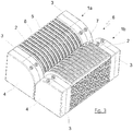
- FIG Figure 1 One possible embodiment of a first connecting link 1a is shown in FIG Figure 1 shown.
- the electrical contacts 2 are surrounded by two magnetic elements 3.
- the magnetic elements 3 are located at the two front ends of the connecting link 1a.
- the connecting member 1a has a cross-sectional area 4 in the form of a square with a rounded corner.
- the cross-sectional area 4 resembles a segment of a circle, more precisely a quarter circle segment.
- the magnetic elements 3 are designed as permanent magnets 3 and can be made from a cylinder magnet, for example.
- the magnetic elements 3 can thus have poles N, S separated in the axial direction.
- the number of contacts 2 that a connecting member 1a has can be arbitrary, preferably greater than two and less than a hundred, particularly preferably between two and fifty, very particularly preferably between ten and twenty. In the embodiment of Figure 1 thirteen contacts 2 are provided. Depressions 5 are provided between the contacts 2 in order to enable a mechanical demonstration, preferably a rough guide. The contacts 2 themselves are individually set back within electrically insulated framing elements 8.
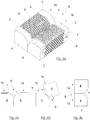
- FIG 2 a second link 1b is shown.
- This connecting member 1b is designed to be magnetically and electrically connected to the first connecting member 1a Figure 1 to be able to form a pair of connections 6.
- the thirteen contacts 2 are again surrounded by two magnetic elements 3, which are designed as permanent magnets 3.
- the two permanent magnets 3 each have a north and a south pole and are arranged at the ends of the connecting member 1b in such a way that one end of the connecting member 1b has a polarity N and the other end of the connecting member 1b has a polarity S.
- the distribution of the poles N, S is chosen to be complementary to that of the magnetic elements 3 of the first connecting member 1a.
- the arrangement of the magnetic elements 3 has the effect that the magnetic force supports the contacting of the connecting links 1a, 1b in only one orientation.
- dome-like framing elements 7 are shown for mechanical demonstration, in particular for rough guidance, in an embodiment as protruding, dome-like framing elements 7, such that the framing elements 7 of the connecting member 1b of the Figure 2 in the correspondingly formed recesses 5 of the connecting member 1 a of Figure 1 fit, it being possible to provide a certain amount of play here, so that a rough guide is preferably provided.
- the dome-like framing elements 7 each comprise an electrical contact 2 of the second connecting member 1b of the Figure 2 .
- the electrical contacts 2 are set back slightly and are preferably supported by spring elements.
- the dome-like framing elements 7 are designed in such a way that they penetrate into the recesses 5 of the connecting member 1a and thereby encompass the framing elements 8 of the contacts 2 of the connecting member 1a.
- a possible assembly of the magnetic elements 3 on the connecting links 1a, 1b or the contact part of the connecting links 1a, 1b is shown in the form of a dovetail connection 9. Another connection or fastening can also be provided here.
- the connecting links 1a, 1b of Figures 1 and 2 can be found in the dimensions AE as an example. Although the proportions of the components to one another are not to be understood as being restricted as a result and all dimensions can be scaled as required, some particularly advantageous dimensions are mentioned below.
- the height or width A of the cross-sectional area 4 or the end face of the connecting link 1a can be approximately 8 mm.
- the height or width of the cross-sectional area 4 or the end face of the connecting member 1b including the dome-like framing elements 7 protruding in height and in width is likewise approximately 8 mm. That is to say, the magnetic elements 3 of the second connecting member 1b have a height or width that is less than the height or width of the protrusion of the dome-like framing elements 7 than the magnetic elements 3 of the first connecting member 1a.
- the length B of the connecting links 1a, 1b can be approximately 20 mm.
- the distance C between the center lines of two contacts 2 can be approximately 1.05 mm.
- the width D of a contact 2, which can be arranged slightly set back in the electrically insulating frame element 8, is preferably approximately 0.3 mm.
- the width E of the electrical contact 2 of the second link 1b, the is preferably mounted radially spring-loaded and surrounded by the dome-like framing element 7, can for example be approximately 0.2 mm.
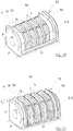
- FIG 3 is shown how the connecting links 1a, 1b of the Figures 1 and 2 form a pair of connections 6.
- the dovetail connection 9 for attaching the magnetic elements 3 to the connecting links 1a, 1b is not shown; this can be any.
- One possible implementation can also be done by gluing, for example.
- the connecting members 1a, 1b are magnetically and electrically connected to one another.
- a mechanical demonstration, in the exemplary embodiment a rough guide is provided which, however, does not hold the connecting links 1a, 1b together, but only takes on a guiding function and prevents axial movement.
- the connecting links 1a, 1b can initially be roughly approximated, whereby the magnetic elements 3, given the correct orientation, which are shown in FIG Figure 3 is shown, make the final contact exactly.
- the coding of the connecting links 1a, 1b with the aid of the magnetic poles N, S of the magnetic elements 3 ensures that the connecting links 1a, 1b only make contact in a predetermined orientation and can then be rotated with respect to one another or can roll over one another.
- the magnetic and electrical connection between the connecting members 1a, 1b of a pair of connections takes place via their jacket surface or a partial surface of the jacket surface. This is shown accordingly in all the exemplary embodiments. While the connecting links 1a, 1b roll over one another, the axes of the connecting links 1a, 1b preferably continue to run parallel to one another.
- FIG. 13 is a simplified view of the interconnection of the links of FIG Figures 1a and 2a shown, whereby the fastening of the magnetic elements 3 by means of a dovetail connection 9 - shown there - can take place.
- the connecting member 1a according to FIGS Figures 1 and 1a preferably has a housing 50, preferably made of plastic, which forms the framing elements 8.
- the housing 50 is in Figure 1a designated.
- the connecting member 1b according to FIGS Figures 2 and 2a preferably has a housing 70, preferably made of plastic, which is shown in Figure 2a is designated.
- the housing 70 preferably forms the dome-like framing elements 7.
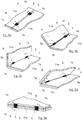
- the Figure 4a shows the side view of a pair of connections 6. Due to the illustrated cross-sectional areas 4 of the connecting links 1a, 1b, it is possible to roll them off one another in the form of a circular movement. The course of such a movement is in the following Figures 4b and 4c indicated.
- the Figure 4a shows an orientation of zero angular degrees of the connecting links 1a, 1b relative to one another, the Figure 4b an orientation greater than ninety degrees and the Figure 4c an alignment of one hundred and eighty degrees after the full rolling motion is complete.
- the movement is of course reversible and can be repeated as often as required.
- the rotation can also be stopped permanently at any angular position. According to the invention, the magnetic or electrical contact is not lost.
- the axes of the connecting links 1a, 1b remain aligned parallel to one another while the connecting links 1a, 1b roll over one another.
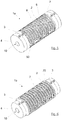
- a second embodiment show Figures 5, 6 and 7th .
- the contacts 2 are surrounded by the magnetic elements 3.
- the magnetic elements 3 are arranged at the front ends of the connecting links 1a, 1b.
- the connecting links 1a, 1b now have a cross-sectional area 4 in the form of a complete circle.
- the attachment of the magnetic elements 3 to the contact parts of the connecting links 1 a, 1 b is implemented by a connection or fastening 10, which can be designed as a round plug connection 10.
- a connection or fastening 10 which can be designed as a round plug connection 10.
- the second connecting member 1b shown has dome-like framing elements 7 in the form of circular areas with larger radii than the cross-sectional area 4.
- magnetic elements 3 are according to the Figures 1 and 2 arranged. Exactly to the contacts 2 of the connecting member 1a of the Figure 5 are in the Figure 6 corresponding contacts 2 distributed and preferably sprung.
- a resulting pair of connections 6 is spatially in the Figure 7 shown; the Figure 8 shows a side view.
- the connection pair As an extension of the exemplary embodiments according to Figures 1 to 4 it is with the connection pair after Figure 7 Due to the complete circular cross-section, it is possible to roll the connecting links 1a, 1b completely, that is to say by up to three hundred and sixty degrees and beyond, on one another.
- the connecting links 1a and 1b only roll or roll over one another over 180 degrees, this simplifies the connection of the contacts 2 of the connecting links 1a, 1b to further units.
- the contacts 2 of the connecting member 1 a are at least partially surrounded by framing elements 8.
- the framing elements 8 are encompassed by the dome-like framing elements 7 of the connecting member 1b when the dome-like framing elements 7 penetrate into the depressions 5.
- At least one contact 2 of each contact pair is preferably spring-loaded; in principle, both contacts of a contact pair 2 can also be spring-loaded.
- the connecting member 1 a preferably has a housing 50, preferably made of plastic, which forms the framing elements 8.
- the connecting member 1b preferably has a housing 70, preferably made of plastic, which forms the dome-like framing elements 7.
- FIG. 5 to 7 an arrangement of the two magnet elements 3 is shown in such a way that the first connecting member 1a has a north pole at one end and a south pole at the other end.
- the second connecting member 1b has a correspondingly complementary south pole at one end and a north pole at the other end.
- the connecting links 1a, 1b can only be closed in one orientation with magnetic support.
- the magnetic elements 3 are arranged in such a way that the first connecting member 1a has a south pole or a north pole at both end faces and the second connecting member 1b is designed in a correspondingly complementary manner, in this case a connection of the connecting members 1a, 1b is in two orientations, which around 180 degrees are rotated to each other, possible. This may be suitable for certain embodiments.
- the connecting members 1a, 1b are preferably connected to an electronic unit 11a, 11b or arranged on this or connectable to it.
- a mobile phone, a tablet or an electronic unit can preferably also be connected to a shell, a docking station, a housing, a cover, a base or a receiving part.
- FIGS. 9a to 9e show an exemplary application of the invention.
- Two units 11a, 11b are shown, each of which preferably has two connecting members 1a, 1b.
- the connecting links 1a, 1b preferably have two magnetic elements 3, which are preferably arranged on the front side of the connecting links 1a, 1b.
- the first unit 11a has a first connecting member 1a and a second connecting member 1b; the second unit 11b has a complementary structure.
- connection pairs 6 A total of two connection pairs 6 are formed.
- the connecting links 1a, 1b shown are preferably those of the first exemplary embodiment, ie there is a cross-section 4 in the form of a square rounded at one end. However, it can also be the connecting links 1a, 1b of the second or third exemplary embodiment.
- the units 11a, 11b shown can be identical units or else different units.
- a connection can be established between two identical or different mobile telephones, a mobile computer and a keyboard or docking station or the like.
- the Figure 13 shows a connection between two identical cell phones 12 or tablets.
- connection device makes the connection of the two units 11a, 11b flexible in an advantageous manner.
- the units 11a, 11b can be rotated relative to one another or pivoted to one another in the manner of a hinge or joint.
- One possible turning movement is beginning in its sequence in Figure 9a and ending at Figure 9e shown.
- a rotation of up to one hundred and eighty degrees of the elements 11a, 11b relative to one another is possible.
- the number of connecting links 1a, 1b in the units 11a, 11b can be arbitrary. It is also possible to use only one connecting link 1a or 1b per unit or even more than two connecting links 1a, 1b.
- By appropriately arranging the connecting links 1a, 1b, preferably symmetrically or optionally asymmetrically, and a corresponding arrangement of the magnetic elements 3 on the connecting links 1a, 1b it can be achieved that the magnetic connecting device only supports the connection of the units 11a, 11b in one orientation or a connection is also possible in two orientations (rotated by 180 angular degrees to one another) so that the alignment of the units 11a, 11b can be varied, whereby in both cases a rotation of the units 11a, 11b to one another (as in Figures 9a to 9e shown) is possible.
- the unit 11a can have connecting members 1a or connecting members 1b or a mixture, as already described above, of the connecting members 1a, 1b.
- the unit 11b can be equipped in a correspondingly complementary manner.
- each unit has a connecting member 1a and a connecting member 1b so that the units can be connected together.
- the Figure 10 shows a third embodiment for a first connecting member 1a.
- a cross-sectional area 4 in the form of a square with a rounded corner is used again.
- the contacts 2 are magnetic elements 3.
- the contact or magnetic elements 2, 3 are surrounded by a mechanical demonstration, preferably a rough guide 13, which can also serve as a frame for the simultaneous protection of all contacts 2 from short circuits.
- An embodiment with four contacts 2 is shown. This embodiment is particularly suitable for forming a USB plug connection.
- the counterpart to the in Figure 10 The first link 1a shown, the second link 1b, is shown in FIG Figure 11 shown.
- the second connecting member 1b is designed in such a way that its mechanical and magnetic guidance is complementary to that of the first connecting member 1a.
- the contacts 2 or magnetic elements 3 on the respective connecting links 1a, 1b are each equally oriented such that the north and south poles of all magnetic elements 3 of a connecting link 1a and 1b are on the same side.
- Other configurations are also possible here in order to achieve a different coding.
- not all contacts 2 are made magnetic. It can be particularly advantageous if only the power or ground contacts are made magnetic in order to avoid interference.
- other data or signal contacts in particular if slow data transmission is provided and interference is less likely, can also be designed to be magnetic.
- further magnet elements 3, which are not provided for electrical contacting can also be used in the embodiment according to FIGS Figures 10 to 12 can be added.
- the mechanical coarse guide 13 for prepositioning or for coarse positioning is provided in order to avoid an axial movement of the connecting members 1a, 1b with respect to one another.
- the axial positioning can thus be taken over in a simple manner by the mechanical rough guide, while the holding force between the connecting members 1a, 1b, in particular in the radial direction, is taken over by the magnetic force.
- the elements of the connecting links 1 a, 1 b, which form the mechanical coarse guide 13, are designed as partially annular elevations 14.
- the partially annular elevations 14 essentially follow the curved course of the jacket or surface of the connecting links 1a, 1b, ie they have an arcuate course (partially annular) which ends in a straight line at the ends.
- the two partially annular elevations 14 of the first connecting member 1a are formed on the front ends of the connecting member.
- the two partially annular elevations 14 of the second connecting member 1b are moved inwards from the end faces approximately by the thickness of the partially annular elevations 14 of the first connecting member 1a, so that the partially annular elevations 14 of the two connecting members 1a, 1b are side by side when the connecting members 1a , 1b are electrically and magnetically connected to one another.
- the formation of two such mechanical connection pairs prevents a displacement of the connecting links 1a, 1b in both axial directions of movement.
- the height and width F of the cross-sectional area 4 of the first connecting member 1a can be approximately 7.5 mm, for example.
- the height and width F of the cross-sectional area 4 of the second connecting member 1b is also approximately 7.5 mm.
- the length G of a link 1a, 1b can be approximately 15 mm.
- the distance H between the center line of two contacts 2 or magnetic elements 3 can be approximately 2.5 mm.
- the width I of a contact 2 or magnetic element 3 can be approximately 1.5 mm.
- the protrusion J by which the partially annular elevation 14 protrudes over the jacket surface can preferably be approximately 1 mm.
- the distance is selected such that when the two connecting links 1a, 1b are plugged together, the contacts 2 of the connecting links 1a, 1b make contact with one another. This is supported by a magnetic configuration of the contacts 2. Furthermore, it can be provided that one or both contacts 2 of a contact pair 2 are mounted radially spring-loaded.
- the dimensions are particularly advantageous, but the explanations are not limited to them.
- the dimensions can differ in particular +/- 80%, preferably +/- 50% and very particularly preferably +/- 20%.
- Figure 12 is the formation of a connecting pair 6 of the connecting links 1a, 1b of the third embodiment of FIG Figures 10 and 11 shown as an example.
- the illustrated units 11a, 11b can also be equipped with the connecting members 1a, 1b of the third embodiment, in particular also with the number of contacts 2 selected there.
- FIG 13 it is shown how a connection between two cell phones 12 or two tablets by two connection pairs 6 can look like.
- An embodiment is shown in which the connecting links 1a, 1b have a cross-section 4 according to the first or third embodiment of the connecting links 1a, 1b, and four contacts 2 are surrounded by magnet elements 3 arranged at the end.
- it is possible to move the cell phones 12 towards one another in the direction of the arrow.
Landscapes
- Engineering & Computer Science (AREA)
- Theoretical Computer Science (AREA)
- Computer Hardware Design (AREA)
- Human Computer Interaction (AREA)
- Physics & Mathematics (AREA)
- General Engineering & Computer Science (AREA)
- General Physics & Mathematics (AREA)
- Signal Processing (AREA)
- Computer Networks & Wireless Communication (AREA)
- Details Of Connecting Devices For Male And Female Coupling (AREA)
- Telephone Set Structure (AREA)
Description
- Die Erfindung betrifft eine magnetische Verbindungsvorrichtung zur Verbindung von zwei Einheiten.
- Grundsätzlich ist eine solche magnetische Verbindungsvorrichtung zur Herstellung jeder erdenklichen Verbindung einsetzbar und damit insbesondere für die Herstellung einer elektrischen Verbindung geeignet.
- Zur Herstellung einer physikalischen elektrischen Verbindung zweier Einheiten sind im Stand der Technik und in der Praxis mechanische Steckverbinder weit verbreitet. Durch diese ist es möglich genannte Einheiten entweder direkt oder über eine Kabelverbindung mechanisch und elektrisch miteinander zu koppeln. Bekannte Probleme solcher Steckverbindungen sind Abnutzungs- und Alterungserscheinungen durch wiederholtes Trennen und Kontaktieren der Stecker bis hin zu einem Stecker- und/oder Kabelbruch bzw. einer dauerhaften Beschädigung der Steckverbindung bei mechanischer Überbeanspruchung. Vor allem durch die feste bzw. starre Positionierung der üblichen Steckverbinder kann leicht eine mechanische Überbeanspruchung, beispielsweise durch Verdrehen der Einheiten zueinander, auftreten. Eine flexiblere Steckverbindung kann nur durch hohen, technischen und somit wirtschaftlichen Aufwand, beispielsweise durch spezielle Gelenkverbindungen, realisiert werden. Weiterhin zeigen selbst diese Maßnahmen in Folge häufiger Beanspruchung Verschleißerscheinungen, wodurch die Lebensdauer der Einheiten bzw. deren Komponenten entsprechend einschränkt ist.
- Zur Lösung dieser Probleme und Umgehung einer notwendigen starren mechanischen Kupplung der Steckverbinder sind im Stand der Technik magnetische Verbindungsvorrichtungen bekannt. Beispielsweise wird in der
DE 10 2008 038 649 A1 eine Vorrichtung zum Herstellen einer Verbindung zwischen einem elektrischen Gerät und einem mit dem Gerät verbindbaren Kabel bzw. einer weiteren elektrischen Vorrichtung vorgestellt. Die Vorrichtung soll einen Adapter mit zwei Adapterteilen mit Magnetelementen umfassen, wodurch eine Verbindung des elektrischen Gerätes mit einem weiteren elektrischen Gerät, z. B. einem Ladegerät, einem Kopfhörer, einem Mikrofon oder einem Headset, geschaffen wird. Die Verbindung soll in einem ersten Schritt durch eine Grobführung über wenigstens einen Vorsprung und einen ringförmigen Rücksprung erfolgt, wozu ein entsprechend großes Spiel vorgesehen ist. Nach der Grobführung erfolgt im zweiten Schritt über die Magnetkräfte der Magnetelemente eine exakte Positionierung und Zentrierung der beiden Adapterteile zueinander. - Ein wesentlicher Vorteil dabei ist, dass der Benutzer die beiden Teile nur grob einander annähern muss und dabei nicht auf eine korrekte Kontaktierung und Zuordnung von Kontakten geachtet werden muss. Damit können Verbindungen auch an schwer zugänglichen Stellen schnell und mühelos vorgenommen werden. Gleichzeitig ist dabei sichergestellt, dass es im Falle einer zur hohen Belastung der Verbindung, durch die es z. B. zu Beschädigungen von Bauteilen kommen könnte, zu einer Lösung der Verbindung kommt, sobald die magnetischen Haltekräfte durch eine höhere Kraft von außen überwunden werden.
- Die magnetische Verbindungsvorrichtung nach der
DE 10 2008 038 649 A1 gibt die Ausrichtung der Steckelemente bzw. Verbindungsglieder zueinander fest vor. Somit wird beispielsweise eine Verdrehung der elektrischen Geräte relativ zueinander nicht toleriert und würde zwingend zum Öffnen der magnetischen und somit auch der elektrischen Verbindung führen. Die Flexibilität, beispielsweise einer Kabelverbindung, ist folglich durch die genaue Vorgabe des Annährungswinkels stark eingeschränkt. Sollen zwei elektrische Geräte direkt miteinander verbunden werden, wie z.B. mobile elektrische Geräte, Dockingstationen oder Eingabegeräte, so kann durch die fest vorgegebene Orientierung insbesondere der Benutzerkomfort deutlich reduziert sein. - Insbesondere bei mobilen elektrischen Geräten, wie z. B. Tablets, tragbaren Computern und Mobiltelefonen, kann es von Vorteil sein, Bildschirme, Tastaturen oder weitere elektrische Geräte zueinander gelenkig bzw. drehbar miteinander zu verbinden. Hierzu sind aus dem Stand der Technik gelenkig mechanische Verbindungen (Scharniere) bekannt.
- Die gattungsgemäße Druckschrift
WO 2010/088695 A1 betrifft eine flexible magnetische Verbindung. In einer Ausführungsform offenbart dieWO 2010/088695 A1 eine Vorrichtung mit einem eine Ausnehmung aufweisenden Modul. Eine magnetische Anordnung ist in der Ausnehmung bewegbar und eine flexible Schaltung wirkt mit dem Modul zusammen, um die magnetische Anordnung in der Ausnehmung zu halten. Die Bewegung der magnetischen Anordnung wird durch magnetische Anziehung zwischen der magnetischen Anordnung und einer äußeren magnetischen Anordnung verursacht. Die flexible Schaltung enthält einen nachgiebigen Kontakt, der durch die Bewegung der magnetischen Anordnung seine Form zu verändern vermag. - Außerdem wird auf die
US 2014/273546 A1 verwiesen, die ein elektrisches Verbindungssystem, insbesondere ein magnetisches Verbindungssystem, für elektronische Geräte offenbart. Ferner betrifft dieWO 2014/120966 A1 einen elektrischen Kontakt und eine Steckverbindertechnik. DieUS 6,272,324 B1 offenbart tragbare Funkkommunikationsvorrichtungen mit einer Klappdeckel. DieUS 2013/170126 A1 betrifft ein mobiles Gerät mit zwei verbindbaren Gehäuseteilen zur Ausbildung verschiedenen Varianten zur Verwendung des Geräts. Außerdem betrifft dieUS 4,865,553 A einen elektrischen Steckverbinder zur Verwendung mit verschiedenen elektronischen Gerätschaften. Schließlich betrifft dieWO 03/100792 A2 - Der vorliegenden Erfindung liegt die Aufgabe zugrunde, eine vorteilhafte gelenkige bzw. drehbare Verbindung zwischen zwei Einheiten zu schaffen.
- Diese Aufgabe wird durch die Ansprüche 1 und 14 gelöst.
- Es wird vorgeschlagen, nach Anspruch 1, dass einer ersten Einheit wenigstens ein erstes Verbindungsglied und einer zweiten Einheit wenigstens ein zweites Verbindungsglied zugeordnet ist, wobei ein erstes Verbindungsglied und ein zweites Verbindungsglied ein Verbindungspaar bilden, wobei die Verbindungsglieder eines Verbindungspaares jeweils eine Mehrzahl von Kontakten aufweisen, wobei die Verbindungsglieder eines Verbindungspaares zueinander achsparallel angeordnet sind und magnetisch miteinander kontaktieren und wobei die Verbindungsglieder eines Verbindungspaares im kontaktierten Zustand relativ zueinander verdrehbar sind.
- Bei der ersten Einheit und der zweiten Einheit handelt es sich vorzugsweise um elektrische oder elektronische Einheiten. Bei der Mehrzahl von Kontakten handelt es sich vorzugsweise um elektrische Kontakte, welche zur Übertragung von Daten und/oder Signalen und/oder zur Stromführung vorgesehen sind. Die Verbindungsglieder eines Verbindungspaares sind magnetisch miteinander verbunden. Ergänzend zu der magnetischen Verbindung ist eine mechanische Grobführung vorgesehen, um die Herstellung des Kontakts zwischen den Verbindungsgliedern und somit zwischen den Einheiten zu vereinfachen.
- Die erfindungsgemäße magnetische Verbindungsvorrichtung zur Verbindung von zwei Einheiten ist insbesondere zur lösbaren Verbindung zwischen zwei Einheiten vorgesehen, das heißt, dass die beiden Einheiten temporär miteinander verbunden und anschließend wieder getrennt werden können. Vorzugsweise können durch wenigstens ein Verbindungspaar die nachfolgenden Einheiten verbunden werden.
- (A) zwei Tablets,
- (B) zwei Mobiltelefone,
- (C) ein Tablet und/oder ein Mobiltelefon und/oder eine elektronische Einheit
- (D) ein Tablet oder ein Mobiltelefon oder eine elektronische Einheit mit einer Tastatur und/oder einem Bildschirm oder einer weiteren elektronischen Einheit.
- Vorzugsweise können erfindungsgemäß auch ein Mobiltelefon, ein Tablet oder eine elektronische Einheit mit einer Schale, einer Dockingstation, einem Gehäuse, einer Abdeckung, einem Sockel oder einem Aufnahmeteil verbunden werden.
- Die erfindungsgemäße magnetische Verbindungsvorrichtung eignet sich darüber hinaus auch, den Bildschirm eines tragbaren Computers, insbesondere eines Laptops, eines Notebooks oder eines Netbooks, derart zu gestalten, dass der Bildschirm von diesem abnehmbar ist.
- Die magnetische Verbindungsvorrichtung zur Verbindung von zwei Einheiten kann derart ausgebildet sein, dass die beiden Einheiten nur in einer Orientierung miteinander verbindbar sind. Dadurch wird eine präzise und eindeutige Verbindung der beiden elektrischen Einheiten sichergestellt. Alternativ kann jedoch beispielsweise auch vorgesehen sein, dass die beiden Einheiten um 180° verdreht miteinander verbindbar sind, derart, dass in einer ersten Orientierung, beispielsweise bei einem Laptop, der Bildschirm und die Tastatur, wenn diese in einer Ebene nebeneinander liegen, in die gleiche Richtung ausgerichtet sind, während in der um 180° gedrehten Anordnung der Bildschirm und die Tastatur, wenn diese flach in einer Ebene nebeneinander liegen, in zwei um 180° verschiedene Richtungen ausgerichtet sind. In Kombination damit, dass erfindungsgemäß vorgesehen ist, dass die Verbindungsglieder eines Verbindungspaares, mittels derer die Einheiten miteinander verbunden sind, zueinander verdrehbar sind, dass sich also der Winkel zwischen den verbundenen Einheiten verändern lässt, ergibt sich eine sehr flexible und anpassungsfähige Ausrichtung der Einheiten zueinander, die auf den gewünschten Einsatzzweck abgestimmt werden kann.
- Die Erfindung ist nicht auf eine verdrehende Bewegung der Verbindungsglieder zueinander beschränkt. Andere Bewegungsarten, von einer einfachen linearen Bewegung über eine rotierende Bewegung bis hin zu einem komplexen Kurvenverlauf der Bewegung, sind ebenfalls realisierbar.
- Im Gegensatz zum bekannten Stand der Technik ist es durch die erfindungsgemäße Ausgestaltung der Verbindungsglieder möglich, eine gelenkige Verbindung zwischen zwei Einheiten, z. B. einem elektrischen bzw. elektronischen Geräts und einem weiteren Gerät und/oder einem Kabel, herzustellen. Insbesondere können die verbundenen Einheiten zueinander verdreht bzw. bewegt werden, ohne dass die magnetische bzw. elektrische Verbindung getrennt wird. Dies stellt nicht nur eine deutlich robustere Verbindung dar als im Stand der Technik bekannt, sondern erhöht auch deutlich den Bedienkomfort für einen Benutzer. Durch die erfindungsgemäße Lösung kann eine wirtschaftlich günstige, langlebige und robuste Steckverbindung gewährleistet werden.
- Erfindungsgemäß kann vorgesehen sein, dass die Verbindungsglieder eines Verbindungspaares jeweils wenigstens ein Magnetelement zur magnetischen Kontaktierung umfassen und wenigstens ein Magnetelement eines Verbindungspaares als Permanentmagnet ausgebildet ist.
- Die genannte Ausführung ist von Vorteil, um die magnetische Kontaktierung einfach und wirtschaftlich zu realisieren. Durch die Verwendung von Permanentmagneten im Gegensatz zu beispielsweise einem Elektromagneten muss kein zusätzlicher Aufwand insbesondere in Form elektrischer Energie in die Verbindung bzw. deren Einsatz investiert werden. Ein Fachmann kann allerdings beliebige andere Realisierungen der Magnetelemente vorsehen, bis hin zu einem Elektropermanentmagneten. Die Verwendung eines Elektropermanentmagneten kann unter Umständen sogar von besonderem Vorteil sein, da sich ein solcher Magnet durch einen elektrischen Impuls "programmieren" bzw. in Magnetkraft und Ausrichtung variieren lässt. Die magnetische Verbindungsvorrichtung ist dadurch noch anpassungsfähiger.
- Mit einem "Magnetelement" kann auch ein Element bzw. eine Anordnung gemeint sein, auf die ein Magnet eine magnetische Kraft ausübt. Beispielsweise kann an einem ersten Verbindungsglied ein Permanentmagnet und an einem zweiten Verbindungsglied ein beliebiges ferromagnetisches Material, beispielsweise ein weichmagnetisches Material, wie z. B. Eisen, vorgesehen sein.
- Vorzugsweise weisen beide Verbindungsglieder eines Verbindungspaars Permanentmagnete auf.
- Die Permanentmagnete sind vorzugsweise derart angeordnet und ausgerichtet, dass ein Permanentmagnet eines ersten Verbindungsglieds eines Verbindungspaars einen Permanentmagnet des anderen Verbindungsglieds des Verbindungspaars kontaktiert, wenn die Einheiten in der vorgesehenen Orientierung miteinander verbunden sind.
- Erfindungsgemäß kann vorgesehen sein, dass die Verbindungsglieder, die Magnetelemente und die Kontakte eines Verbindungspaares derart ausgebildet sind, dass im Falle einer magnetischen Kontaktierung die Kontakte der jeweiligen Verbindungsglieder elektrisch miteinander kontaktieren.
- Erfindungsgemäß kann vorgesehen sein, dass die Kontaktierung der Verbindungsglieder eines Verbindungspaars über ihre Mantelfläche bzw. ihren Umfang erfolgt. Im Unterschied dazu kontaktieren bekannte magnetische Verbindungsvorrichtungen stirnseitig.
- Erfindungsgemäß kann vorgesehen sein, dass die Verbindungsglieder eines Verbindungspaars im kontaktierten Zustand durch ein Abwälzen bzw. Abrollen entlang ihrer Mantelfläche bzw. ihres Umfangs zueinander verdrehbar sind. Die bekannten stirnseitigen magnetischen Verbindungsvorrichtungen sind im Unterschied dazu nur um dieselbe Achse bzw. koaxial rotierbar.
- Die Achsen der erfindungsgemäßen Verbindungsglieder eines Verbindungspaars sind vorzugsweise parallel, jedoch nicht koaxial angeordnet. Bei der erfindungsgemäß möglichen Verdrehung der Verbindungsglieder bleibt die achsparallele Ausrichtung der Verbindungsglieder bestehen, während sich die Verbindungsglieder aufeinander abwälzen bzw. abrollen. Vorzugsweise rotiert eine Achse eines Verbindungsglieds eines Verbindungspaars um die Achse des anderen Verbindungsglieds. Vorzugsweise bleibt der Abstand zwischen den Achsen dabei im Wesentlichen unverändert.
- In einer Ausführung der Erfindung können die Magnetelemente derart ausgebildet sein, dass die Verbindungsglieder eines Verbindungspaares in wenigstens einer vorbestimmten Orientierung elektrisch und magnetisch kontaktierbar sind und sich in dieser Orientierung magnetisch anziehen, wobei die Verbindungsglieder eines Verbindungspaares derart gestaltet sind, dass sich die Verbindungsglieder eines Verbindungspaares im kontaktierten Zustand bei einer relativen Verdrehung zueinander zumindest über eine Teilfläche der Mantelfläche bzw. des Umfangs der Verbindungsglieder aufeinander abwälzen bzw. abrollen, wobei die elektrische und magnetische Kontaktierung bestehen bleibt.
- Die Erfinder haben erkannt, dass sich eine Verdrehung der ersten Einheit zu der zweiten Einheit, wie sie zum Beispiel üblich ist, um den Bildschirm eines Laptops auf- oder zuzuklappen bzw. in seiner Ausrichtung gegenüber der Tastatur zu verschwenken, besonders einfach und zuverlässig durch die erfindungsgemäßen Verbindungsglieder umsetzen lässt, wenn die Verbindungsglieder eines Verbindungspaares derart gestaltet sind, dass sich die Verbindungsglieder im kontaktierten Zustand bei einer relativen Verdrehung zueinander über eine Teilfläche ihrer Mantelfläche bzw. ihres Umfangs aufeinander abwälzen bzw. abrollen. Dabei sind die Verbindungsglieder sowie die Kontakte derart gestaltet, dass bei der Abwälz- bzw. Abrollbewegung die elektrische und die magnetische Kontaktierung erhalten bleibt.
- Eine Bewegung der Verbindungsglieder eines Verbindungspaares derart, dass diese zumindest über eine Teilfläche der aufeinander ausgerichteten Mantelflächen der Verbindungsglieder aufeinander abwälzen bzw. abrollen, lässt sich unabhängig davon realisieren, ob die Verbindung zwischen den beiden Einheiten nur in einer Orientierung geschlossen werden kann oder ob auch eine zweite, vorzugsweise um 180° versetzte Anordnung, oder noch weitere Orientierungen möglich sind. Im Rahmen der Erfindung ist vorzugsweise vorgesehen, dass die Einheiten in nur einer Orientierung oder in zwei Orientierungen miteinander verbindbar sind. Unter Orientierung ist dabei das grundsätzliche Verbinden der beiden Einheiten zu verstehen, beispielsweise ob ein Bildschirm bei der Verbindung mit einer Tastatur auf den Benutzer ausgerichtet ist oder um 180° verdreht ist und in die andere Richtung zeigt. Analog ist darunter bei der Verbindung von zwei Mobiltelefonen miteinander zu verstehen, ob die Bildschirme der Mobiltelefone bei der Verbindung, wenn diese flach nebeneinander liegen, in dieselbe Richtung zeigen oder in entgegengesetzte Richtungen. Ähnliches gilt bei der Verbindung von zwei Tablets oder beim Verbinden eines Tablets oder eines Mobiltelefons mit einer Dockingstation. Die sich aus den erfindungsgemäßen Verbindungsgliedern ergebende Verdrehbarkeit (insbesondere realisiert durch ein Abwälzen der Verbindungsglieder), die auch zu einer Verdrehbarkeit der miteinander verbundenen Einheiten führt, ist unabhängig davon gegeben, ob die Einheiten in einer, zwei oder mehreren Orientierungen miteinander verbindbar sind.
- Erfindungsgemäß kann, wie bereits ausgeführt, vorgesehen sein, dass die Einheiten in mehr als einer Orientierung, insbesondere in genau zwei Orientierungen, miteinander verbindbar sind, insbesondere in zwei um 180° zueinander verschiedenen Orientierungen. Dies kann sich insbesondere für die Verbindung von Tastaturen mit Bildschirmen oder zur Verbindung von zwei Tablets oder zur Verbindung von zwei Mobiltelefonen oder zur Verbindung eines Tablets und eines Mobiltelefons mit einer weiteren elektronischen Einheit eignen.
- Erfindungsgemäß kann vorgesehen sein, dass die Magnetelemente der Verbindungsglieder eines Verbindungspaares hinsichtlich ihrer Polarität derart ausgerichtet sind, dass sich die Verbindungsglieder eines Verbindungspaares nur in einer Orientierung der ersten Einheit zu der zweiten Einheit magnetisch anziehen.
- Mit einer vorbestimmten Orientierung ist an dieser Stelle gemeint, dass beispielsweise bei zwei Verbindungsgliedern deren Kontakte nur in einer vorbestimmten Zuordnung zur gegenseitigen Verbindung vorgesehen sind. Insbesondere sollen die Einheiten nicht "falsch herum" miteinander verbunden werden können, wodurch z. B. ein technischer Defekt vermieden werden kann.
- Erfindungsgemäß kann dabei auch vorgesehen sein, dass in alternativen Orientierungen die Magnetelemente nicht kontaktieren bzw. eine einander abstoßende Magnetkraft erfahren. Einem Benutzer kann durch die abstoßende Magnetkraft signalisiert werden, dass sich eine der Einheiten bzw. eines der Verbindungsglieder in einer falschen Orientierung befindet. Außerdem kann eine ungewollte und unbemerkte Falschkontaktierung verhindert werden wenn die Einheiten sich zueinander in Ortsnähe befinden und frei bzw. unkontrolliert beweglich sind, wie beispielsweise während eines Transportvorgangs.
- Erfindungsgemäß kann vorgesehen sein, dass die Verbindungsglieder eines Verbindungspaares jeweils wenigstens zwei Magnetelemente aufweisen.
- Die Verwendung von mehr als einem Magnetelement kann in vorteilhafter Weise eine magnetische Kraftwirkung (Haltekraft und Abstoßkraft) der magnetischen Verbindungsvorrichtung erhöhen. Weiter kann durch die entsprechende Wahl der Anzahl der Magnetelemente eine bestimmte Haltekraft festgelegt werden.
- In einer Ausführung der Erfindung kann vorgesehen sein, dass die Ausrichtung der Pole der Magnetelemente bzw. die Verteilung der Magnetelemente selbst an den Verbindungsgliedern die vorbestimmte Orientierung oder die vorbestimmten Orientierungen vorgibt.
- Eine entsprechende Verteilung der Magnetelemente bzw. deren Pole über die Verbindungsglieder der Einheiten kann als eine Art Kodierung verstanden werden, die die gewünschte Orientierung der Verbindungsglieder zueinander zur Kontaktierung festlegt. Wenn jedes Verbindungsglied eines Verbindungspaares zwei Magnetelemente aufweist, lässt sich durch die Ausrichtung der beiden Magnetelemente auf dem jeweiligen Verbindungsglied definieren, ob die Einheiten nur in einer oder in zwei Orientierungen geschlossen werden können bzw. ob nur eine Orientierung magnetisch unterstützt oder ob zwei Orientierungen magnetisch unterstützt werden.
- Wenn die beiden Magnetelemente eines Verbindungsglieds symmetrisch bezogen auf die Längsachse des Verbindungsglieds um den Mittelpunkt bzw. um eine sich durch den Mittelpunkt erstreckende Querschnittsfläche des Verbindungsglieds angeordnet sind und die Magnetelemente derart ausgerichtet sind, dass jeweils der gleiche Pol nach innen bzw. der gleiche Pol der beiden Magnetelemente nach außen zeigt, dann kann ein Verbindungsglied, bei dem jeweils die Gegenpole identisch angeordnet sind, in zwei Orientierungen verbunden werden. Beispielsweise kann bei einem Verbindungsglied vorgesehen sein, dass die Nordpole der Magnetelemente jeweils nach außen und somit die Südpole nach innen ausgerichtet sind, während bei dem damit zu verbindenden anderen Verbindungsglied die Südpole nach außen und die Nordpole nach innen ausgerichtet sind.
- Wenn durch die Anordnung der Magnetelemente erreicht werden soll, dass die Einheiten nur in einer Orientierung zu verbinden sind, dann kann entweder vorgesehen sein, dass die Magnetelemente auf den Verbindungsgliedern asymmetrisch zu einem Mittelpunkt (in Achsrichtung betrachtet) anordnet sind oder die Magnetelemente auf einem Verbindungsglied hinsichtlich ihrer Pole identisch ausgerichtet sind, d. h. beispielsweise zeigen jeweils die Nordpole nach links und die Südpole nach rechts. Bei einem damit zu verbindenden Verbindungsglied ist dann vorgesehen, dass jeweils die Südpole entsprechend nach links und die Nordpole entsprechend nach rechts ausgerichtet sind. Damit ist eine Verbindung der Verbindungsglieder nur in einer Ausrichtung möglich.
- Erfindungsgemäß kann vorgesehen sein, dass die miteinander zu verbindenden Einheiten jeweils nur über ein Verbindungsglied verfügen. Das Verbindungsglied kann dabei ein oder zwei oder auch mehrere Magnetelemente aufweisen.
- Erfindungsgemäß kann ferner vorgesehen sein, dass die miteinander zu verbindenden Einheiten jeweils über zwei oder mehrere Verbindungsglieder verfügen. Insbesondere das Vorsehen von zwei Verbindungsgliedern pro Einheit hat sich als vorteilhaft herausgestellt, da sich damit die Einheiten, beispielsweise ein Bildschirm mit einer Tastatur, besonders stabil verbinden lassen. Die Verbindungsglieder können dabei wiederum jeweils über ein Magnetelement oder über zwei oder mehrere Magnetelemente verfügen. Es hat sich als vorteilhaft herausgestellt, zwei Magnetelemente pro Verbindungsglied vorzusehen.
- Eine besonders geeignete magnetische Verbindungsvorrichtung ergibt sich, wenn die zu verbindenden Einheiten jeweils zwei Verbindungsglieder mit jeweils zwei Magnetelementen aufweisen.
- Die Magnetelemente der Verbindungsglieder sind vorzugsweise jeweils derart angeordnet und ausgerichtet, dass bei jedem Magnetelement beide Pole zur Herstellung der magnetischen Verbindung herangezogen werden.
- Erfindungsgemäß ist vorzugsweise vorgesehen, dass die Magnetelemente der Verbindungsglieder derart ausgerichtet sind, dass die Pole der Magnetelemente nebeneinander in der Achse des Verbindungsglieds liegen, vorzugsweise derart, dass bei einem Zylinder- oder Stabmagneten die Achse des Zylinder- oder Stabmagneten in der Achse des Verbindungsglieds liegt. Dies bildet einen Unterschied zu einer bekannten flachen Anordnung von Magneten, bei denen nur entweder der Nord- oder der Südpol zur Verbindung herangezogen ist, während der jeweils andere Pol von dem zu verbindenden Bauteil abgewandt ist.
- Erfindungsgemäß kann somit vorzugsweise vorgesehen sein, dass bei jedem Magnetelement sowohl der Nord- als auch der Südpol zur Herstellung der Verbindung herangezogen wird, so dass bildlich dargestellt bei jedem Magnetelement eine Nordpol- oder eine Südpolscheibe nebeneinander in der Achse des Verbindungsglieds liegen und das Magnetelement bilden.
- Es kann weiter vorgesehen sein, dass wenigstens eine Teilfläche der Mantelflächen der Verbindungsglieder, auf denen die Verbindungsglieder eines Verbindungspaares aufeinander abwälzbar bzw. abrollbar sind, gekrümmt und/oder bogenförmig verläuft und/oder einen Radius aufweist. Die Verbindungsglieder können vorzugsweise eine Querschnittsfläche zumindest annährend in Form eines Kreises aufweisen. Des Weiteren hat sich auch eine Querschnittsfläche in Form eines Quadrats oder eines Rechtecks mit wenigstens einer abgerundeten Ecke bzw. wenigstens einer Ecke, die eine Kreisbogenform aufweist, als besonders geeignet herausgestellt. Dadurch wird in einfacher Weise eine gekrümmt und/oder bogenförmig verlaufende und/oder einen Radius aufweisende Teilfläche geschaffen.
- Von Vorteil ist es, wenn die Teilfläche eine gleichmäßige Krümmung bzw. einen gleichmäßigen Radius aufweist, damit sich die Verbindungsglieder bei einer Verdrehung der Einheiten zueinander gleichmäßig auf der Teilfläche abwälzen können.
- Durch eine gekrümmt und/oder bogenförmige und/oder einen Radius aufweisende Mantel- bzw. Oberfläche bzw. eine entsprechend gestaltete Teilfläche der Mantel- bzw. Oberfläche ist es möglich, dass die Verbindungsglieder eines Verbindungspaares sich aufeinander in abwälzender Form bewegen können, ohne die elektrische Kontaktierung zu lösen. Eine solche Abwälzbewegung ermöglicht eine einfache Realisierung der erfindungsgemäß vorgesehenen Verdrehbarkeit bzw. Bewegbarkeit der Verbindungsglieder. Eine lineare bzw. translatorische oder sonstige Bewegung bei entsprechender Ausgestaltung der Verbindungsglieder ist ebenfalls denkbar.
- Eine weitere Ausführung der Erfindung kann vorsehen, dass die Verbindungsglieder eines Verbindungspaares stabförmig ausgebildet sind, wobei wenigstens eine Teilfläche des Umfangs des jeweiligen Verbindungsglieds derart ausgebildet ist, dass die Verbindungsglieder eines Verbindungspaares aufeinander abwälzbar sind.
- Dabei kann insbesondere vorgesehen sein, die Magnetelemente und/oder die elektrischen Kontakte längs bzw. in Axialrichtung nebeneinander entlang der Verbindungsglieder verteilt anzuordnen.
- Es kann weiter vorgesehen sein, dass die stabförmigen Verbindungsglieder an ihren jeweiligen stirnseitigen Enden ein Magnetelement aufweisen und zwischen den Magnetelementen die Mehrzahl von Kontakten angeordnet ist. Die Magnetelemente können selbstverständlich auch einen Abstand zu den stirnseitigen Enden der Verbindungsglieder aufweisen. Es kann auch vorgesehen sein, dass die Magnetelemente zwischen den Kontakten verteilt angeordnet sind.
- Die Magnetelemente und die Kontakte sind derart angeordnet, dass alle Kontaktstellen bei Vorliegen einer magnetischen Verbindung geschlossen sind. Die Ausbildung von zwei Magnetelementen pro Verbindungsglied hat sich hierfür als besonders geeignet herausgestellt.
- Vorzugsweise können die Kontakte und/oder die Magnetelemente wenigstens über eine Teillänge bzw. die Länge der Teilfläche in Abwälzrichtung der Verbindungsglieder gekrümmt und/oder bogenförmig verlaufen und/oder einen Radius aufweisen.
- Insbesondere eine Anpassung der Krümmung bzw. des Verlaufs bzw. des Radius der Magnetelemente und Kontakte an die Krümmung bzw. den Verlauf bzw. den Radius der zum Abwälzen vorgesehenen Teilfläche der Mantelfläche der Verbindungsglieder kann die vorgesehene Bewegung der Verbindungsglieder unterstützen.
- Es kann vorgesehen sein, dass die Magnetelemente zylinder- und/oder scheiben- und/oder ringförmig und/oder teilringförmig ausgebildet sind.
- Derartige Magnetelemente lassen sich fertigungstechnisch günstig realisieren und eignen sich für eine axiale Anordnung insbesondere derart, dass beide Pole des Magnetelements zur Herstellung einer magnetischen Verbindung eingesetzt werden können. Zur Herstellung kann beispielsweise ein handelsüblicher Stabmagnet durch Kürzen bzw. Zuschneiden leicht in Scheibenform gebracht werden. Auch kann die Scheibe in ihrem Querschnitt anschließend - falls gewünscht - leicht in Kreissegmente zerteilt werden. Ferner kann durch eine Bohrung einfach einen Ringmagnet oder ein ringförmiges Magnetelement gebildet werden.
- Bei derart gestalteten Magnetelementen bilden dann die jeweiligen Längsenden einen Pol mit jeweils gegensätzlicher Polarisierung.
- In einer weiteren Ausführung kann vorgesehen sein, dass wenigstens ein Teil der aufeinander ausgerichteten, elektrisch kontaktierenden Kontakte der Verbindungsglieder eines Verbindungspaares magnetisch miteinander kontaktiert. Dazu kann wenigstens ein Teil der Kontakte als Magnetelemente ausgebildet sein.
- Die Ausbildung der Kontakte als Magnetelemente kann wirtschaftlich sein und die Baugröße der magnetischen Verbindungsvorrichtung insgesamt reduzieren, da Bauteile eingespart werden. Es ist allerdings vorstellbar, dass eine Kombination von elektrischem Kontakt und Magnetelement eine Datenübertragung, insbesondere eine solche mit hoher Datenrate, störend beeinflusst. Demzufolge kann es vorgesehen sein, die elektrischen Kontakte nur teilweise als Magnetelemente auszuführen und insbesondere kritische Kontakte nicht als Magnetelemente zu realisieren. Beispielsweise können vornehmlich elektrische Kontakte die zur reinen elektrischen Versorgung, z. B. Strom- und Massekontakte, oder zur langsamen Datenübertragung verwendet werden als Magnetelemente ausgebildet werden.
- Erfindungsgemäß kann auch vorgesehen sein, dass die Verbindungsglieder Magnetelemente aufweisen, die keine elektrischen Signale übertragen, und zusätzlich Magnetelemente vorgesehen sind, die zur Strom- und Masseübertragung dienen und/oder elektrische Signale übertragen. Erfindungsgemäß kann auch vorgesehen sein, dass alle Kontakte als Magnetelemente ausgebildet sind. Es ist dabei denkbar, dass bei einem Kontaktpaar das im kontaktierten Zustand eine Strom-, Signal- oder Datenübertragung ermöglicht, ein Kontakt als Permanentmagnet ausgebildet ist und der andere Kontakt lediglich magnetisch beeinflussbar ist, beispielsweise durch eine Realisierung als weichmagnetisches Material, insbesondere Eisen.
- Vorzugsweise ist allerdings vorgesehen, dass die Kontakte eines Kontaktpaars entsprechend der vorbeschriebenen Magnetelemente ausgebildet sind, so dass jeder Kontakt zwei Pole aufweist, die axial nebeneinander liegen, d. h. die sich in der Verbindungsachse befindenden axialen Enden eines elektrischen Kontakts weisen jeweils einen der beiden Pole auf.
- Dadurch lässt sich eine besonders starke magnetische Verbindung zwischen den Kontakten eines Kontaktpaares herstellen, die darüber hinaus kodiert sein kann. Insofern mehrere Kontakte als Magnetelemente ausgebildet sind, lässt sich ein spezifischer Code darstellen, der nur eine spezifische Verbindung mit einem entsprechend angepasst kodierten weiteren Verbindungsglied ermöglicht.
- Vorzugsweise ist eine mechanische Vorführung zur Verbindung eines ersten Verbindungsglieds mit einem zweiten Verbindungsglied vorgesehen.
- Erfindungsgemäß weisen die Verbindungsglieder eines Verbindungspaares eine mechanische Führung auf, die als mechanische Grobführung ausgebildet ist, um ein Verbindungspaar zu bilden.
- Eine mechanische Führung unterstützt die Verbindung der zu verbindenden elektronischen Einheiten. Die mechanische Führung ist derart angeordnet, dass diese eine axiale Verschiebung der Verbindungsglieder zueinander verhindert bzw. begrenzt, wodurch die magnetische Verbindung entlastet wird und insbesondere diesbezüglich keine oder nur reduzierte Kräfte kompensieren muss.
- Vorzugsweise ist die mechanische Führung derart gestaltet, dass diese eine Abwälzbewegung bzw. ein Abrollen der Verbindungsglieder aufeinander im kontaktierten Zustand nicht behindert. Dies kann beispielsweise dadurch realisiert werden, dass ein Verbindungsglied eines Verbindungspaares eine vorzugsweise bogenförmig bzw. ringförmig vorspringende Erhebung bzw. ein vorspringendes Teilringsegment aufweist und das zugeordnete zweite Verbindungsglied des Verbindungspaares eine entsprechende Vertiefung aufweist, in die die Erhebung, insbesondere die teilringförmige Erhebung, eindringen kann. Möglich ist auch nur eine punkt- oder domförmige Erhebung, die sich dann in einer teilringförmigen Vertiefung des jeweils anderen Verbindungsglieds bewegen kann, wenn die Verbindungsglieder aufeinander abwälzen.
- Die mechanische Führung kann vorzugsweise zwei Aufgaben übernehmen und dabei zum einen eine mechanische Führung zum Zusammenstecken der Einheiten darstellen und zum anderen eine axiale Bewegung der Verbindungsglieder im kontaktierten Zustand verhindern. Des Weiteren kann die mechanische Führung eine mechanische Kodierung darstellen, um eine Fehlschließung zu vermeiden.
- Die mechanische Führung ist als mechanische Grobführung ausgebildet, beispielsweise auch durch eine entsprechende konische Gestaltung der Erhebung, so dass die mechanische Grobführung ein einfaches Zuführen der Verbindungsglieder zueinander ermöglicht und die exakte und genaue Ausrichtung dann durch die Magnete erfolgt.
- Die mechanische Grobführung kann insbesondere in Form von an einem Verbindungsglied herausragenden domartigen Gebilden und durch entsprechende Vertiefungen an dem als Gegenstück ausgebildeten Verbindungsglied realisiert sein.
- Die mechanische Grobführung des Verbindungsglieds kann zusätzlich auch als Magnetelement ausgebildet sein.
- Eine solche mechanische Grobführung kann dazu dienen, den Komfort für einen Benutzer weiter zu erhöhen. Die Herstellung der Verbindung wird erleichtert. Weiterhin ist eine mit einer mechanischen Grobführung versehene Magnetverbindung robust. Insbesondere im Hinblick auf die erfindungsgemäß vorgesehene Möglichkeit die Einheiten bzw. Verbindungsglieder relativ zueinander zu bewegen bzw. zu verdrehen kann die Möglichkeit eines Kontaktverlusts während dieser Bewegung verringert werden.
- Erfindungsgemäß kann vorgesehen sein, dass jeweils zwei mechanische Führungselemente, vorzugsweise zwei mechanische Grobführungselemente, zumindest einen Kontakt umgeben.
- Durch eine solche weiter verbesserte mechanische Führung bzw. Grobführung wird die Möglichkeit eines Kontaktierungsverlusts während einer Bewegung der Einheiten zueinander weiter gesenkt.
- In einer weiteren Ausgestaltung kann vorgesehen sein, dass die elektrischen Kontakte gegenüber der Mantel- bzw. Oberfläche des Verbindungsglieds zurückversetzt angeordnet sind. Dies kann beispielsweise in Kombination mit der mechanischen Grobführung realisiert werden. Die elektrischen Kontakte können beispielsweise einzeln von elektrisch isolierenden Umrahmungselementen wenigstens teilweise umgeben und innerhalb derselben zurückversetzt angeordnet sein.
- Dadurch, dass die elektrischen Kontakte auf der Mantel- bzw. Oberfläche des Verbindungsglieds zurückversetzt und somit nicht vorstehend ausgebildet sind, reduziert sich die Möglichkeit einer unbeabsichtigten Kontaktierung. Es wird außerdem vermieden, dass elektrische Kontakte eines Verbindungsglieds unbeabsichtigt miteinander kontaktieren, vor allem bei Berührung der Verbindungsglieder mit metallischen bzw. elektrisch leitfähigen Gegenständen. Somit kann ein ungewollter Kurzschluss ausgeschlossen oder zumindest die Wahrscheinlichkeit hierfür gesenkt werden.
- Erfindungsgemäß kann vorgesehen sein, dass die Kontakte beider Verbindungsglieder eines Verbindungspaares gegenüber der Mantel- bzw. Oberfläche des jeweiligen Verbindungsglieds zurückversetzt sind. Dabei können die elektrischen Kontakte jeweils wenigstens teilweise von Umrahmungselementen umgeben und innerhalb derselben zurückversetzt angeordnet sein. Dabei ist vorzugsweise vorgesehen, dass die Umrahmungselemente eines Verbindungsglieds derart gestaltet sind, dass die Umrahmungselemente des anderen Verbindungsglieds in diese eindringen können, um eine elektrische Kontaktierung der jeweils innerhalb der Umrahmungselemente angeordneten elektrischen Kontakte zu ermöglichen. Durch das Eindringen der Umrahmungselemente eines Verbindungsglieds in ein entsprechendes Umrahmungsglied eines zweiten Verbindungsglieds des Verbindungspaares wird zudem eine mechanische Führung bereitgestellt, welche zuverlässig eine axiale Verschiebung der Verbindungsglieder zueinander verhindert.
- In einer Ausgestaltung der Erfindung ist es vorgesehen, dass die Umrahmungselemente eines Verbindungsglieds ausgebildet sind, um die entsprechenden Umrahmungselemente des anderen Verbindungsglieds aufzunehmen. Es ist jedoch auch denkbar, dass nur ein Teil der Umrahmungselemente eines Verbindungsglieds zur Aufnahme der Umrahmungselemente des anderen Verbindungsglieds vorgesehen ist, während ein anderer Teil der Umrahmungselemente des Verbindungsglieds selbst in Umrahmungselemente des anderen Verbindungsglieds eindringt.
- Ergänzend können zudem auch noch weitere mechanische Führungen an den Verbindungsgliedern vorgesehen sein, die nicht zur Umrandung der elektrischen Kontakte dienen, wie vorstehend bereits beschrieben. Des Weiteren können auch die Kontaktelemente selbst, wenigstens teilweise, als Magnete ausgebildet sein und/oder weitere Magnetelemente, die nicht zur elektrischen Kontaktierung vorgesehen sind, vorgesehen sein.
- Weiterhin kann vorgesehen sein, dass die Verbindung der elektrischen Kontakte dadurch gestützt wird, dass die elektrischen Kontakte zumindest eines der Verbindungsglieder des Verbindungspaares radial gefedert gelagert sind.
- Vorzugsweise ist bei jedem Kontaktpaar ein Kontakt radial vorgespannt bzw. gefedert.
- Durch eine solche Lagerung kann die Verbindung der Kontakte über einen längeren mechanischen Weg in radialer Ausdehnung sichergestellt werden bzw. die Kontaktierung wird zuverlässiger. Es kann hierdurch gewährleistet werden, dass insbesondere eine elektrische Verbindung trotz Erschütterungen bzw. Vibrationen an den Einheiten bzw. den Verbindungsgliedern bestehen bleibt, da die Kontakte über eine definierte radiale Wegstrecke nachgeführt werden können. Je nach Anwendung ist selbstverständlich auch eine anderweitig gelagerte Federung oder federähnliche Vorrichtung denkbar.
- Erfindungsgemäß kann auch vorgesehen sein, dass alle elektrischen Kontakte radial gefedert gelagert sind. Grundsätzlich kann eine Federung der Kontakte unabhängig davon vorgesehen sein, ob diese zusätzlich über eine magnetische Ausgestaltung verfügen bzw. als Magnete ausgebildet sind.
- Die Verbindungsglieder sind vorzugsweise mit einer elektronischen Einheit oder einer Einheit, die mit einer elektronischen Einheit zu verbinden ist, verbunden oder an dieser angeordnet oder mit dieser verbindbar.
- Die Anzahl der Kontakte, die ein Verbindungsglied aufweist, kann beliebig sein, vorzugsweise größer als zwei und kleiner als hundert, besonders bevorzugt zwischen fünf und fünfzig, ganz besonders bevorzugt zwischen zehn und zwanzig. In einem Ausführungsbeispiel sind dreizehn Kontakte vorgesehen. In einem weiteren Ausführungsbeispiel sind hingegen vier Kontakte vorgesehen.
- Die Anzahl der Kontakte ist abhängig von den zu verbindenden Einheiten, in einer Ausgestaltung kann es auch von Vorteil sein, wenn die Anzahl der Kontakte zwei bis sechs beträgt, vorzugsweise vier Kontakte vorgesehen sind.
- Die Erfindung eignet sich insbesondere für ein elektronisches System mit wenigstens einer ersten Einheit, einer magnetischen einer zweiten Einheit (11b) und Verbindungsvorrichtung nach einem der Ansprüche 1 bis 13, wobei die Einheiten über die magnetische Verbindungsvorrichtung verbunden sind.
- Vorzugsweise kann ein solches System aus Einheiten wie Mobiltelefonen, Tablets oder sonstigen Computern, Gerätehüllen und Geräteschalen, Dockingstationen, Abdeckungen, Tastaturen oder Bildschirmen bestehen, wobei diese Liste nicht als abgeschlossen zu verstehen ist.
- Details ergeben sich aus den Figuren der Zeichnung, wobei jede Figur für sich ein gesondertes Ausführungsbeispiel darstellt, jedoch zwei oder mehrere der Figuren in beliebiger Kombination auch ein gemeinsames Ausführungsbeispiel darstellen können. Alle Merkmale der Figuren sind optimal und können beliebig miteinander kombiniert werden.
- Es zeigt schematisch:
- Figur 1
- eine räumliche Ansicht eines ersten Verbindungsglieds eines Verbindungspaares in einer ersten Ausführungsform;
- Figur 1a
- eine vereinfachte Darstellung der räumliche Ansicht der
Figur 1 ; - Figur 2
- eine räumliche Ansicht eines zweiten Verbindungsglieds eines Verbindungspaares in der ersten Ausführungsform;
- Figur 2a
- eine vereinfachte Darstellung der räumliche Ansicht der
Figur 2 ; - Figur 3
- eine räumliche Ansicht eines Verbindungspaares nach den
Figuren 1 und2 ; - Figur 3a
- eine vereinfachte Darstellung der räumlichen Ansicht der
Figur 3 ; - Figur 4a
- eine Seitenansicht eines Verbindungspaares mit einer Auslenkung von 0 Winkelgrad;
- Figur 4b
- eine Seitenansicht eines Verbindungspaares mit einer Auslenkung von über 90 Winkelgrad;
- Figur 4c
- eine Seitenansicht eines Verbindungspaares mit einer Auslenkung von 180 Winkelgrad;
- Figur 5
- eine räumliche Ansicht eines ersten Verbindungsglieds eines Verbindungspaares in einer zweiten Ausführungsform;
- Figur 6
- eine räumliche Ansicht eines zweiten Verbindungsglieds eines Verbindungspaares in der zweiten Ausführungsform;
- Figur 7
- eine räumliche Ansicht eines Verbindungspaares nach den
Figuren 5 und 6 ; - Figur 8
- eine Seitenansicht des Verbindungspaares nach
Figur 7 ; - Figur 9a
- eine räumliche Ansicht der Verbindung zweier Einheiten mit zwei Verbindungspaaren bei einer Auslenkung von 0 Winkelgrad;
- Figur 9b
- eine räumliche Ansicht der Verbindung zweier Einheiten mit zwei Verbindungspaaren bei einer Auslenkung von 45 Winkelgrad;
- Figur 9c
- eine räumliche Ansicht der Verbindung zweier Einheiten mit zwei Verbindungspaaren bei einer Auslenkung von 90 Winkelgrad;
- Figur 9d
- eine räumliche Ansicht der Verbindung zweier Einheiten mit zwei Verbindungspaaren bei einer Auslenkung von 135 Winkelgrad;
- Figur 9e
- eine räumliche Ansicht der Verbindung zweier Einheiten mit zwei Verbindungspaaren bei einer Ausrichtung von 180 Winkelgrad;
- Figur 10
- eine räumliche Ansicht eines ersten Verbindungsglieds eines Verbindungspaares in einer dritten Ausführungsform;
- Figur 11
- eine räumliche Ansicht eines zweiten Verbindungsglieds eines Verbindungspaares in der dritten Ausführungsform;
- Figur 12
- eine räumliche Ansicht eines Verbindungspaars nach den
Figuren 10 und 11 ; und - Figur 13
- eine räumliche Ansicht der Verbindung zweier Mobiltelefone und/oder Tablets durch zwei Verbindungspaare.
- Eine mögliche Ausführungsform eines ersten Verbindungsglieds 1a ist in
Figur 1 dargestellt. In dieser Ausführung werden die elektrischen Kontakte 2 von zwei Magnetelementen 3 umgeben. Die Magnetelemente 3 befinden sich an den beiden stirnseitigen Enden des Verbindungsglieds 1a. In gezeigter Ausführung weist das Verbindungsglied 1a eine Querschnittsfläche 4 in Form eines Quadrats mit einer gerundeten Ecke auf. Die Querschnittsfläche 4 ähnelt einem Kreissegment, genauer einem Viertelkreissegments. - Die Magnetelemente 3 sind als Permanentmagnete 3 ausgeführt, und können beispielsweise aus einem Zylindermagneten gefertigt sein. Die Magnetelemente 3 können somit in axialer Richtung separierte Pole N, S aufweisen. Die Anzahl der Kontakte 2 die ein Verbindungsglied 1a aufweist kann beliebig sein, vorzugsweise größer als zwei und kleiner als hundert, besonders bevorzugt zwischen zwei und fünfzig, ganz besonders bevorzugt zwischen zehn und zwanzig. Im Ausführungsbeispiel der
Figur 1 sind dreizehn Kontakte 2 vorgesehen. Zwischen den Kontakten 2 sind Vertiefungen 5 vorgesehen, um eine mechanische Vorführung, vorzugsweise eine Grobführung, zu ermöglichen. Die Kontakte 2 selbst sind einzeln innerhalb elektrisch isolierter Umrahmungselemente 8 zurückversetzt angeordnet. - In
Figur 2 ist ein zweites Verbindungsglied 1b dargestellt. Dieses Verbindungsglied 1b ist ausgebildet, um magnetisch und elektrisch mit dem ersten Verbindungsglied 1a ausFigur 1 ein Verbindungspaar 6 bilden zu können. Die dreizehn Kontakte 2 sind abermals von zwei Magnetelementen 3 umgeben, die als Permanentmagnete 3 ausgebildet sind. Die beiden Permanentmagnete 3 weisen jeweils einen Nord- und einen Südpol auf und sind an den Enden des Verbindungsglieds 1b derart angeordnet, dass ein Ende des Verbindungsglieds 1b eine Polarität N und das andere Ende des Verbindungsglieds 1b eine Polarität S aufweist. Die Verteilung der Pole N, S ist dabei komplementär zu denen der Magnetelemente 3 des ersten Verbindungsglieds 1a gewählt. Die Anordnung der Magnetelemente 3 bewirkt, dass die Magnetkraft die Kontaktierung der Verbindungsglieder 1a, 1b nur in einer Orientierung unterstützt. - Weiter gezeigt sind die Elemente zur mechanischen Vorführung, insbesondere zur Grobführung, in einer Ausführung als vorstehende, domartige Umrahmungselemente 7, derart, dass die Umrahmungselemente 7 des Verbindungsglieds 1b der
Figur 2 in die entsprechend ausgebildeten Vertiefungen 5 des Verbindungsglieds 1a derFigur 1 passen, wobei hier ein gewisses Spiel vorgesehen sein kann, damit vorzugsweise eine Grobführung bereitgestellt wird. Die domartigen Umrahmungselemente 7 umfassen jeweils einen elektrischen Kontakt 2 des zweiten Verbindungsglieds 1b derFigur 2 . Die elektrischen Kontakte 2 sind dabei leicht zurückversetzt und vorzugsweise durch Federelemente gelagert. - Die domartigen Umrahmungselemente 7 sind derart gestaltet, dass diese in die Vertiefungen 5 des Verbindungsglieds 1a eindringen und dabei die Umrahmungselemente 8 der Kontakte 2 des Verbindungsglieds 1a umfassen.
- Eine mögliche Montage der Magnetelemente 3 an den Verbindungsgliedern 1a, 1b bzw. dem Kontaktteil der Verbindungsglieder 1a, 1b ist in Ausführung einer Schwalbenschwanzverbindung 9 gezeigt. Hierbei kann auch eine andere Verbindung bzw. Befestigung vorgesehen sein.
- Den Verbindungsgliedern 1a, 1b der
Figuren 1 und2 sind beispielhaft den Maßangaben A-E zu entnehmen. Obwohl die Größenverhältnisse der Komponenten zueinander hierdurch nicht beschränkt zu verstehen und alle Maße beliebig skalierbar sind, sind im Folgenden einige besonders vorteilhafte Abmessungen genannt. Die Höhe bzw. Breite A der Querschnittsfläche 4 bzw. der Stirnseite des Verbindungsglieds 1a kann ungefähr 8 mm betragen. Die Höhe bzw. Breite der Querschnittsfläche 4 bzw. der Stirnseite des Verbindungsglieds 1b inklusive der in der Höhe und in der Breite überstehenden domartigen Umrahmungselemente 7 beträgt ebenfalls ca. 8 mm. Das heißt, die Magnetelemente 3 des zweiten Verbindungsglieds 1b weisen eine um den Überstand der domartigen Umrahmungselemente 7 geringere Höhe bzw. Breite auf wie die Magnetelemente 3 des ersten Verbindungsglieds 1a. - Die Länge B der Verbindungsglieder 1a, 1b kann ca. 20 mm betragen. Der Abstand C zwischen den Mittellinien zweier Kontakte 2 kann ca. 1,05 mm betragen. Die Breite D eines Kontakts 2, der in dem elektrisch isolierenden Umrahmungselement 8 leicht zurückversetzt angeordnet sein kann, beträgt vorzugsweise ca. 0,3 mm. Die Breite E des elektrischen Kontakts 2 des zweiten Verbindungsglieds 1b, das vorzugsweise radial gefedert gelagert und von dem domartigen Umrahmungselement 7 umgeben ist, kann beispielsweise ca. 0,2 mm betragen.
- In
Figur 3 ist dargestellt, wie die Verbindungsglieder 1a, 1b derFiguren 1 und2 ein Verbindungspaar 6 ausbilden. Dabei ist die Schwalbenschwanzverbindung 9 zur Anbringung der Magnetelemente 3 an den Verbindungsgliedern 1a, 1b nicht gezeigt, diese kann beliebig sein. Eine mögliche Realisierung kann beispielsweise auch durch Kleben erfolgen. Die Verbindungsglieder 1a, 1b sind magnetisch sowie elektrisch miteinander verbunden. Zusätzlich ist eine mechanische Vorführung, im Ausführungsbeispiel eine Grobführung, vorgesehen, welche die Verbindungsglieder 1a, 1b allerdings nicht zusammenhält, sondern nur eine Führungsfunktion übernimmt und eine axiale Bewegung verhindert. Durch die mechanische Grobführung können die Verbindungsglieder 1a, 1b zunächst grob angenähert werden, wodurch die Magnetelemente 3 bei richtiger Orientierung, die inFigur 3 dargestellt ist, die endgültige Kontaktierung exakt vornehmen. Die Kodierung der Verbindungsglieder 1a, 1b mithilfe der Magnetpole N, S der Magnetelemente 3 stellt sicher, dass die Verbindungsglieder 1a, 1b nur in einer vorbestimmten Orientierung kontaktieren und dann zueinander verdrehbar sind bzw. aufeinander abwälzen können. - Die magnetische und die elektrische Verbindung zwischen den Verbindungsgliedern 1a, 1b eines Verbindungspaars erfolgt über deren Mantelfläche bzw. eine Teilfläche der Mantelfläche. Dies ist in allen Ausführungsbeispielen entsprechend dargestellt. Während sich die Verbindungsglieder 1a, 1b aufeinander abwälzen, verlaufen die Achsen der Verbindungsglieder 1a, 1b vorzugsweise weiterhin parallel zueinander.
- Die
Figuren 1a und2a zeigen vereinfachte Ansichten der Darstellungen aus denFiguren 1 und2 , wobei die Maßangaben und die magnetischen Pole N, S nicht dargestellt sind. Die Magnetelemente 3 weisen jeweils zwei Pole N, S auf. InFigur 3a ist eine vereinfachte Ansicht der Verbindung der Verbindungsglieder derFiguren 1a und2a dargestellt, wobei die Befestigung der Magnetelemente 3 mittels einer - dort dargestellten - Schwalbenschwanzverbindung 9 erfolgen kann. - Das Verbindungsglied 1a gemäß den
Figuren 1 und 1a weist vorzugsweise ein Gehäuse 50, vorzugsweise aus Kunststoff, auf, welches die Umrahmungselemente 8 ausbildet. Das Gehäuse 50 ist inFigur 1a bezeichnet. Das Verbindungsglied 1b gemäß denFiguren 2 und 2a weist vorzugsweise ein Gehäuse 70, vorzugsweise aus Kunststoff, auf, welches inFigur 2a bezeichnet ist. Das Gehäuse 70 bildet dabei vorzugsweise die domartigen Umrahmungselemente 7 aus. - Die
Figur 4a zeigt die Seitenansicht eines Verbindungspaares 6. Aufgrund der dargestellten Querschnittsflächen 4 der Verbindungsglieder 1a, 1b ist es möglich, diese in Form einer Kreisbewegung aufeinander abzuwälzen. Der Verlauf einer solchen Bewegung ist in den folgendenFiguren 4b und 4c angedeutet. DieFigur 4a zeigt dabei eine Ausrichtung von null Winkelgrad der Verbindungsglieder 1a, 1b relativ zueinander, dieFigur 4b eine Ausrichtung von mehr als neunzig Winkelgrad und dieFigur 4c eine Ausrichtung von einhundertachtzig Winkelgrad nach Vollziehen der vollständigen Abwälzbewegung. - Selbstverständlich ist die Bewegung reversibel und beliebig oft wiederholbar. Die Verdrehung kann an einer beliebigen Winkelstellung auch dauerhaft gestoppt werden. Erfindungsgemäß geht dabei die magnetische oder elektrische Kontaktierung nicht verloren.
- Die Achsen der Verbindungsglieder 1a, 1b bleiben, während sich die Verbindungsglieder 1a, 1b aufeinander abwälzen, parallel zueinander ausgerichtet.
- Eine zweite Ausführungsform zeigen die
Figuren 5, 6 und7 . Auch in diesem Beispiel sind die Kontakte 2 von den Magnetelementen 3 umgeben. Die Magnetelemente 3 sind an den stirnseitigen Enden der Verbindungsglieder 1a, 1b angeordnet. Die Verbindungsglieder 1a, 1b weisen nun allerdings eine Querschnittsfläche 4 in Form eines vollständigen Kreises auf. Die Anbringung der Magnetelemente 3 an den Kontaktteilen der Verbindungsglieder 1a, 1b ist durch eine Verbindung bzw. Befestigung 10 realisiert, welche als runde Steckverbindung 10 ausgeführt sein kann. Abermals ist eine mechanische Vorführung, vorzugsweise eine Grobführung, vorhanden, bei der die Kontakte 2 des ersten Verbindungsglieds 1a von entsprechenden Vertiefungen 5 umgeben sind. Das inFigur 6 gezeigte zweite Verbindungsglied 1b weist domartige Umrahmungselemente 7 in Form von Kreisflächen mit größeren Radien als die Querschnittsfläche 4 auf. Um die Verbindung nur in einer vorbestimmten Orientierung zu ermöglichen, sind Magnetelemente 3 entsprechend denFiguren 1 und2 angeordnet. Passgenau zu den Kontakten 2 des Verbindungsglieds 1a derFigur 5 sind in derFigur 6 entsprechende Kontakte 2 verteilt und vorzugsweise gefedert. - Ein resultierendes Verbindungspaar 6 ist räumlich in der
Figur 7 dargestellt; dieFigur 8 zeigt eine Seitenansicht. In Erweiterung der Ausführungsbeispiele nach denFiguren 1 bis 4 ist es bei dem Verbindungspaar nachFigur 7 durch den vollständigen Kreisquerschnitt möglich, die Verbindungsglieder 1a, 1b vollständig, d. h. um bis zu dreihundertsechzig Winkelgrad und darüber hinaus, aufeinander abzuwälzen. - Vorzugsweise ist auch bei dem Ausführungsbeispiel gemäß den
Figuren 5 bis 8 vorgesehen, dass die Verbindungsglieder 1a und 1b nur über 180 Winkelgrad aufeinander abwälzen bzw. abrollen, dies vereinfacht es, die Kontakte 2 der Verbindungsglieder 1a, 1b an weiterführende Einheiten anzuschließen. - Die Kontakte 2 des Verbindungsglieds 1a sind von Umrahmungselementen 8 wenigstens teilweise umgeben. Die Umrahmungselemente 8 werden dabei von den domartigen Umrahmungselementen 7 des Verbindungsglieds 1b umfasst, wenn die domartigen Umrahmungselemente 7 in die Vertiefungen 5 eindringen. Vorzugsweise ist wenigstens ein Kontakt 2 jedes Kontaktpaares gefedert, grundsätzlich können auch beide Kontakte eines Kontaktpaares 2 gefedert ausgebildet sein.
- Das Verbindungsglied 1a weist vorzugsweise ein Gehäuse 50, vorzugsweise aus Kunststoff, auf, welches die Umrahmungselemente 8 ausbildet. Das Verbindungsglied 1b weist vorzugsweise ein Gehäuse 70, vorzugsweise aus Kunststoff, auf, welches die domartigen Umrahmungselemente 7 ausbildet.
- In den
Figuren 5 bis 7 ist eine Anordnung der beiden Magnetelemente 3 derart gezeigt, dass das erste Verbindungsglied 1a an einem stirnseitigen Ende einen Nordpol und an dem anderen stirnseitigen Ende einen Südpol aufweist. Das zweite Verbindungsglied 1b weist entsprechend komplementär an einem Ende einen Südpol und an dem anderen Ende einen Nordpol auf. Dadurch wird erreicht, dass die Verbindungsglieder 1a, 1b magnetisch unterstützt nur in einer Orientierung geschlossen werden können. Insofern die Magnetelemente 3 derart angeordnet sind, dass das erste Verbindungsglied 1a an beiden stirnseitigen Enden einen Südpol oder einen Nordpol aufweist und das zweite Verbindungsglied 1b entsprechend komplementär gestaltet ist, ist in diesem Fall eine Verbindung der Verbindungsglieder 1a, 1b in zwei Orientierungen, die um 180 Winkelgrad zueinander verdreht sind, möglich. Dies kann für bestimmte Ausführungsformen geeignet sein. - Die Verbindungsglieder 1a, 1b sind vorzugsweise mit einer elektronischen Einheit 11a, 11b verbunden oder an dieser angeordnet oder mit dieser verbindbar.
- Vorzugsweise können durch wenigstens ein Verbindungspaar 6 die nachfolgenden Einheiten 11a, 11b verbunden werden:
- (A) zwei Tablets,
- (B) zwei Mobiltelefone,
- (C) ein Tablet und/oder ein Mobiltelefon und/oder eine elektronische Einheit
- (D) ein Tablet oder ein Mobiltelefon oder eine elektronische Einheit mit einer Tastatur und/oder einem Bildschirm oder einer weiteren elektronischen Einheit.
- Vorzugsweise können auch ein Mobiltelefon, ein Tablet oder eine elektronische Einheit mit einer Schale, einer Dockingstation, einem Gehäuse, einer Abdeckung, einem Sockel oder einem Aufnahmeteil verbunden werden.
- Die
Figuren 9a bis 9e zeigen eine beispielhafte Anwendung der Erfindung. Gezeigt sind zwei Einheiten 11a, 11b, die vorzugsweise jeweils zwei Verbindungsglieder 1a, 1b aufweisen. Die Verbindungsglieder 1a, 1b weisen vorzugsweise zwei Magnetelemente 3, die vorzugsweise stirnseitig an den Verbindungsgliedern 1a, 1b angeordnet sind, auf. Die erste Einheit 11a weist dabei jeweils ein erstes Verbindungsglied 1a und ein zweites Verbindungsglied 1b auf; die zweite Einheit 11b ist komplementär dazu aufgebaut. - Insgesamt werden zwei Verbindungspaare 6 gebildet. Die dargestellten Verbindungsglieder 1a, 1b sind vorzugsweise die des ersten Ausführungsbeispiels, d. h. es liegt ein Querschnitt 4 in Form eines an einem Ende abgerundeten Quadrats vor. Es kann sich aber auch um die Verbindungsglieder 1a, 1b des zweiten oder dritten Ausführungsbeispiels handeln.
- Bei den dargestellten Einheiten 11a, 11b kann es sich um identische Einheiten oder aber um unterschiedliche Einheiten handeln. So kann eine Verbindung beispielsweise zwischen zwei gleichen oder aber unterschiedlichen Mobiltelefonen, einem mobilen Computer und einer Tastatur oder Dockingstation oder ähnlichem hergestellt werden. Die
Figur 13 zeigt eine Verbindung zwischen zwei identischen Mobiltelefonen 12 oder Tablets. - Durch die erfindungsgemäße Verbindungsvorrichtung ist die Verbindung beider Einheiten 11a, 11b in vorteilhafter Weise flexibel. Die Einheiten 11a, 11b sind relativ zueinander verdrehbar bzw. nach Art eines Scharniers bzw. Gelenks zueinander verschwenkbar. Eine mögliche Drehbewegung ist in ihrem Ablauf beginnend in
Figur 9a und endend beiFigur 9e dargestellt. Bei einer Querschnittsfläche 4 gemäß der ersten Ausführungsform der Verbindungsglieder 1a, 1b ist dabei - wie dargestellt - eine Verdrehung um bis zu einhundertachtzig Winkelgrad der Elemente 11a, 11b relativ zueinander möglich. - Die Anzahl der Verbindungsglieder 1a, 1b bei den Einheiten 11a, 11b kann beliebig sein. Es ist auch möglich, nur ein Verbindungsglied 1a bzw. 1b pro Einheit zu verwenden oder auch mehr als zwei Verbindungsglieder 1a, 1b. Durch eine entsprechende Anordnung der Verbindungsglieder 1a, 1b, vorzugsweise symmetrisch oder gegebenenfalls auch asymmetrisch, und eine entsprechende Anordnung der Magnetelemente 3 auf den Verbindungsgliedern 1a, 1b kann erreicht werden, dass die magnetische Verbindungsvorrichtung nur die Verbindung der Einheiten 11a, 11b in einer Orientierung unterstützt oder eine Verbindung auch in zwei Orientierungen (um 180 Winkelgrad zueinander verdreht) möglich ist, so dass die Ausrichtung der Einheiten 11a, 11b variiert werden kann, wobei in beiden Fällen eine Verdrehung der Einheiten 11a, 11b zueinander (wie in den
Figuren 9a bis 9e dargestellt) möglich ist. - Die Einheit 11a kann über Verbindungsglieder 1a oder Verbindungsglieder 1b oder über eine Mischung, wie vorstehend bereits beschrieben, der Verbindungsglieder 1a, 1b verfügen. Die Einheit 11b kann entsprechend komplementär ausgerüstet sein.
- Insbesondere zur Verbindung zweier baugleicher Einheiten ist es von Vorteil, wenn jede Einheit ein Verbindungsglied 1a und ein Verbindungsglied 1b aufweist, so dass die Einheiten zusammengeschlossen werden können.
- Die
Figur 10 zeigt eine dritte Ausführung für ein erstes Verbindungsglied 1a. In diesem Beispiel wird abermals eine Querschnittsfläche 4 in Form eines Quadrats mit einer abgerundeten Ecke verwendet. Gezeigt ist die Möglichkeit, die Kontakte 2 als Magnetelemente 3 auszubilden. Hierbei sind die Kontakt- bzw. Magnetelemente 2, 3 von einer mechanischen Vorführung, vorzugsweise einer Grobführung 13, umgeben, die zudem als Rahmen zum gleichzeitigen Schutz aller Kontakte 2 vor Kurzschlüssen dienen kann. Gezeigt ist eine Ausführung mit vier Kontakten 2. Diese Ausführung eignet sich insbesondere zur Bildung einer USB-Steckverbindung. - Das Gegenstück zu dem in
Figur 10 gezeigten, ersten Verbindungsglied 1a, das zweite Verbindungsglied 1b, ist inFigur 11 dargestellt. Das zweite Verbindungsglied 1b ist dabei so ausgebildet, dass dessen mechanische und magnetische Führung komplementär zu der des ersten Verbindungsglieds 1a ist. - Wie sich aus den
Figuren 10 bis 12 ergibt, sind die Kontakte 2 bzw. Magnetelemente 3 auf den jeweiligen Verbindungsgliedern 1a, 1b jeweils gleichermaßen orientiert derart, dass sich die Nord- bzw. Südpole aller Magnetelemente 3 eines Verbindungsglieds 1a bzw. 1b auf derselben Seite befinden. Hier sind auch andere Gestaltungen möglich, um eine anderweitige Kodierung zu erreichen. Möglich ist es zudem, dass im Ausführungsbeispiel gemäß denFiguren 10 bis 12 nicht alle Kontakte 2 magnetisch ausgebildet sind. Es kann insbesondere von Vorteil sein, wenn nur die Strom- oder Massekontakte magnetisch ausgebildet sind, um Störungen zu vermeiden. Darüber hinaus können gegebenenfalls auch noch weitere Daten- oder Signalkontakte, insbesondere wenn eine langsame Datenübertragung vorgesehen und eine Störung weniger wahrscheinlich ist, magnetisch ausgebildet sein. Zusätzlich können, wie in den ersten und zweiten Ausführungsformen der Verbindungsglieder 1a, 1b dargestellt, auch noch weitere Magnetelemente 3, die nicht zur elektrischen Kontaktierung vorgesehen sind, in dem Ausführungsbeispiel nach denFiguren 10 bis 12 ergänzt werden. - Wie sich aus den
Figuren 10 bis 12 ferner ergibt, ist die mechanische Grobführung 13 zur Vorpositionierung bzw. zur Grobpositionierung dazu vorgesehen, eine axiale Bewegung der Verbindungsglieder 1a, 1b zueinander zu vermeiden. Die axiale Positionierung kann somit in einfacher Weise durch die mechanische Grobführung übernommen werden, während die Haltekraft zwischen den Verbindungsgliedern 1a, 1b, insbesondere in radialer Richtung, durch die Magnetkraft übernommen wird. Die Elemente der Verbindungsglieder 1a, 1b, welche die mechanische Grobführung 13 bilden, sind als teilringförmige Erhöhungen 14 ausgebildet. Die teilringförmigen Erhöhungen 14 folgen hinsichtlich ihrer Kontur im Wesentlichen dem gebogenen Verlauf der Mantel- bzw. Oberfläche der Verbindungsglieder 1a, 1b, d. h. diese weisen einen bogenförmigen Verlauf (teilringförmig) auf, der an den Enden in eine Gerade ausläuft. Die beiden teilringförmigen Erhöhungen 14 des ersten Verbindungsglieds 1a sind an den stirnseitigen Enden des Verbindungsglieds ausgebildet. Die beiden teilringförmigen Erhöhungen 14 des zweiten Verbindungsglieds 1b sind in etwa um die Stärke der teilringförmigen Erhöhungen 14 des ersten Verbindungsglieds 1a von den Stirnseiten nach innen gerückt, so dass die teilringförmigen Erhöhungen 14 der beiden Verbindungsglieder 1a, 1b seitlich aneinander liegen, wenn die Verbindungsglieder 1a, 1b elektrisch und magnetisch miteinander verbunden sind. Die Ausbildung von zwei derartigen mechanischen Verbindungspaaren verhindert eine Verschiebung der Verbindungsglieder 1a, 1b in beide axiale Bewegungsrichtungen. - Obwohl es dem Fachmann ohne Weiteres möglich ist, die Verbindungsglieder 1a, 1b und die Größen derer Bestandteile beliebig zu variieren, sind im Folgenden einige besonders vorteilhafte Maßangaben genannt. Die Höhe und Breite F der Querschnittsfläche 4 des ersten Verbindungsglieds 1a kann beispielsweise ca. 7,5 mm betragen. Die Höhe und Breite F der Querschnittsfläche 4 des zweiten Verbindungsglieds 1b beträgt ebenfalls ca. 7,5 mm. Die Länge G eines Verbindungsglieds 1a, 1b kann ungefähr 15 mm betragen. Der Abstand H zwischen der Mittellinie zweier Kontakte 2 bzw. Magnetelemente 3 kann etwa 2,5 mm betragen. Die Breite I eines Kontakts 2 bzw. Magnetelements 3 kann ungefähr 1,5 mm betragen. Der Überstand J um den die teilringförmige Erhebung 14 über die Mantelfläche vorsteht, kann vorzugsweise ca. 1 mm betragen. Der Abstand ist dabei derart gewählt, dass, wenn die beiden Verbindungsglieder 1a, 1b zusammengesteckt sind, die Kontakte 2 der Verbindungsglieder 1a, 1b miteinander kontaktieren. Dies wird durch eine magnetische Ausgestaltung der Kontakte 2 unterstützt. Ferner kann vorgesehen sein, dass einer oder beide Kontakte 2 eines Kontaktpaares 2 radial gefedert gelagert sind.
- In den
Figuren 1 ,2 ,10 und 11 sind die Maßangaben besonders vorteilhaft, hierauf sind die Ausführungen jedoch nicht beschränkt. Die Maßangaben können insbesondere +/- 80%, vorzugsweise +/- 50 % und ganz besonders bevorzugt +/- 20% differieren. - In
Figur 12 ist die Bildung eines Verbindungspaares 6 der Verbindungsglieder 1a, 1b der dritten Ausführungsform derFiguren 10 und 11 beispielhaft dargestellt. - Die in den
Figuren 9a bis 9e dargestellten Einheiten 11a, 11b können auch mit den Verbindungsgliedern 1a, 1b der dritten Ausführungsform, insbesondere auch mit der dort gewählten Anzahl an Kontakten 2, ausgerüstet sein. - In
Figur 13 ist dargestellt, wie eine Verbindung zweier Mobiltelefone 12 oder zweier Tablets durch zwei Verbindungspaare 6 aussehen kann. Gezeigt ist eine Ausführung, bei der die Verbindungsglieder 1a, 1b einen Querschnitt 4 nach der ersten oder der dritten Ausführungsform der Verbindungsglieder 1a, 1b aufweisen, und wobei jeweils vier Kontakte 2 von stirnseitig angeordneten Magnetelementen 3 umgeben sind. Erfindungsgemäß ist es möglich, die Mobiltelefone 12 in Pfeilrichtung aufeinander zu zu bewegen. Es liegt somit eine gelenkige, bzw. drehbare Verbindung vor. Insbesondere wäre es vorstellbar, die Mobiltelefone 12 elektronisch derart zu koppeln, dass die Anzeigefläche eines Mobiltelefons 12 auf die Anzeigefläche bzw. das Display des zweiten Mobiltelefons 12 erweiterbar ist. Beispielsweise wäre es dann möglich, die Mobiltelefone 12 derart zusammen zu klappen, dass diese rückseitig aneinander liegen, wobei die jeweiligen Displays der Mobiltelefone 12 nach außen zeigen. Insbesondere würde dadurch ein Anzeigegerät geschaffen, das ein beidseitiges Display aufweist.
Claims (14)
- Magnetische Verbindungsvorrichtung zur Verbindung von zwei Einheiten, wobei einer ersten Einheit (11a) wenigstens ein erstes Verbindungsglied (1a) und einer zweiten Einheit (11b) wenigstens ein zweites Verbindungsglied (1b) zugeordnet ist, wobei ein erstes Verbindungsglied (1a) und ein zweites Verbindungsglied (1b) ein Verbindungspaar (6) bilden, wobei die Verbindungsglieder (1a, 1b) eines Verbindungspaares (6) jeweils eine Mehrzahl von Kontakten (2) aufweisen, wobei die Verbindungsglieder (1a, 1b) eines Verbindungspaares (6) zueinander achsparallel angeordnet sind und magnetisch miteinander kontaktieren und wobei die Verbindungsglieder (1a, 1b) eines Verbindungspaares (6) im kontaktierten Zustand relativ zueinander verdrehbar sind,
dadurch gekennzeichnet, dass
die Verbindungsglieder (1a, 1b) eines Verbindungspaares (6) eine mechanische Führung (5,7 bzw. 13) aufweisen, die ausgebildet ist, um eine axiale Bewegung der Verbindungsglieder (1a, 1b) im kontaktierten Zustand zu begrenzen, und wobei die mechanische Führung (5, 7 bzw. 13) als mechanische Grobführung ausgebildet ist, so dass die mechanische Grobführung ein einfaches Zuführen der Verbindungsglieder zueinander ermöglicht und die exakte und genaue Ausrichtung dann magnetisch erfolgt. - Magnetische Verbindungsvorrichtung nach Anspruch 1,
dadurch gekennzeichnet, dass
die Verbindungsglieder (1a, 1b) eines Verbindungspaares (6) jeweils wenigstens ein Magnetelement (3) zur magnetischen Kontaktierung umfassen und wenigstens ein Magnetelement (3) eines Verbindungspaares (6) als Permanentmagnet ausgebildet ist. - Magnetische Verbindungsvorrichtung nach Anspruch 2,
dadurch gekennzeichnet, dass
die Verbindungsglieder (1a, 1b), die Magnetelemente (3) und die Kontakte (2) eines Verbindungspaares (6) derart ausgebildet sind, dass im Falle einer magnetischen Kontaktierung die Kontakte (2) der jeweiligen Verbindungsglieder (1a, 1b) elektrisch miteinander kontaktieren. - Magnetische Verbindungsvorrichtung nach Anspruch 2, oder 3,
dadurch gekennzeichnet, dass
die Magnetelemente (3) derart ausgebildet sind, dass die Verbindungsglieder (1a, 1b) eines Verbindungspaares (6) in wenigstens einer vorbestimmten Orientierung elektrisch und magnetisch kontaktierbar sind und sich in dieser Orientierung magnetisch anziehen, wobei die Verbindungsglieder (1a, 1b) eines Verbindungspaares (6) derart gestaltet sind, dass sich die Verbindungsglieder (1a, 1b) eines Verbindungspaares (6) im kontaktierten Zustand bei einer relativen Verdrehung zueinander zumindest über eine Teilfläche der Mantelfläche der Verbindungsglieder (1a, 1b) aufeinander abwälzen lassen, wobei die elektrische und magnetische Kontaktierung bestehen bleibt. - Magnetische Verbindungsvorrichtung nach einem der Ansprüche 2 bis 4,
dadurch gekennzeichnet, dass
die Magnetelemente (3) der Verbindungsglieder (1a, 1b) eines Verbindungspaares (6) hinsichtlich ihrer Polarität derart ausgerichtet sind, dass sich die Verbindungsglieder (1a, 1b) eines Verbindungspaares (6) nur in einer Orientierung der ersten Einheit (11a) zu der zweiten Einheit (11b) magnetisch anziehen. - Magnetische Verbindungsvorrichtung nach einem der Ansprüche 2 bis 5,
dadurch gekennzeichnet, dass
die Verbindungsglieder (1a, 1b) eines Verbindungspaares (6) jeweils wenigstens zwei Magnetelemente (3) aufweisen. - Magnetische Verbindungsvorrichtung nach einem der Ansprüche 4 bis 6,
dadurch gekennzeichnet, dass
wenigstens eine Teilfläche der Mantelflächen der Verbindungsglieder (1a, 1b), auf denen die Verbindungsglieder (1a, 1b) eines Verbindungspaares (6) aufeinander abwälzbar sind, gekrümmt und/oder bogenförmig verläuft und/oder einen Radius aufweist. - Magnetische Verbindungsvorrichtung nach Anspruch 7,
dadurch gekennzeichnet, dass
die Verbindungsglieder (1a, 1b) eines Verbindungspaares (6) stabförmig ausgebildet sind. - Magnetische Verbindungsvorrichtung nach Anspruch 8,
dadurch gekennzeichnet, dass
die stabförmigen Verbindungsglieder (1a, 1b) an ihren jeweiligen stirnseitigen Enden ein Magnetelement (3) aufweisen und zwischen den Magnetelementen (3) die Mehrzahl von Kontakten (2) angeordnet ist. - Magnetische Verbindungsvorrichtung nach einem der Ansprüche 4 bis 9,
dadurch gekennzeichnet, dass
die Kontakte (2) und/oder die Magnetelemente (3) wenigstens über die Länge der Teilfläche in Abwälzrichtung der Verbindungsglieder (1a, 1b) gekrümmt und/oder bogenförmig verlaufen und/oder einen Radius aufweisen. - Magnetische Verbindungsvorrichtung nach einem der Ansprüche 2 bis 10,
dadurch gekennzeichnet, dass
die Magnetelemente (3) zylinder- und /oder scheiben- und/oder ringförmig und/oder teilringförmig ausgebildet sind. - Magnetische Verbindungsvorrichtung nach einem der Ansprüche 1 bis 11,
dadurch gekennzeichnet, dass
wenigstens ein Teil der aufeinander ausgerichteten, elektrisch kontaktierenden Kontakte (2) der Verbindungsglieder (1a, 1b) eines Verbindungspaares (6) magnetisch miteinander kontaktiert. - Magnetische Verbindungsvorrichtung nach Anspruch 12,
dadurch gekennzeichnet, dass
wenigstens ein Teil der Kontakte (2) als Magnetelemente (3) ausgebildet ist. - Elektronisches System mit wenigstens einer ersten Einheit (11a), einer zweiten Einheit (11b) und einer magnetischen e Verbindungsvorrichtung nach einem der Ansprüche 1 bis 13,
dadurch gekennzeichnet, dass
die Einheiten (11a, 11b) über die magnetische Verbindungsvorrichtung verbunden sind.
Applications Claiming Priority (3)
| Application Number | Priority Date | Filing Date | Title |
|---|---|---|---|
| DE102014116948 | 2014-11-19 | ||
| DE102015116490.6A DE102015116490A1 (de) | 2014-11-19 | 2015-09-29 | Magnetische Verbindungsvorrichtung |
| PCT/EP2015/076145 WO2016078962A1 (de) | 2014-11-19 | 2015-11-10 | Magnetische verbindungsvorrichtung |
Publications (2)
| Publication Number | Publication Date |
|---|---|
| EP3221929A1 EP3221929A1 (de) | 2017-09-27 |
| EP3221929B1 true EP3221929B1 (de) | 2022-01-05 |
Family
ID=55855489
Family Applications (1)
| Application Number | Title | Priority Date | Filing Date |
|---|---|---|---|
| EP15791307.0A Active EP3221929B1 (de) | 2014-11-19 | 2015-11-10 | Magnetische verbindungsvorrichtung |
Country Status (9)
| Country | Link |
|---|---|
| US (1) | US10177490B2 (de) |
| EP (1) | EP3221929B1 (de) |
| JP (1) | JP2017536671A (de) |
| KR (1) | KR20170083034A (de) |
| CN (1) | CN107112686B (de) |
| CA (1) | CA2965419A1 (de) |
| DE (3) | DE202015009067U1 (de) |
| TW (1) | TWI691125B (de) |
| WO (1) | WO2016078962A1 (de) |
Families Citing this family (11)
| Publication number | Priority date | Publication date | Assignee | Title |
|---|---|---|---|---|
| WO2015070321A1 (en) * | 2013-11-13 | 2015-05-21 | Szeto Timothy Jing Yin | Magnetic connectors |
| DE202015009067U1 (de) * | 2014-11-19 | 2016-08-24 | Rosenberger Hochfrequenztechnik Gmbh & Co. Kg | Magnetische Verbindungsvorrichtung |
| KR20170058081A (ko) * | 2015-11-18 | 2017-05-26 | 삼성전자주식회사 | 자석으로 연결되는 장치 |
| KR102435011B1 (ko) * | 2017-05-22 | 2022-08-23 | 삼성전자주식회사 | 액세사리를 포함하는 전자 장치 |
| TWI675282B (zh) * | 2018-05-14 | 2019-10-21 | 緯創資通股份有限公司 | 具有樞軸結構之電子裝置及其訊號連接單元的製造方法 |
| WO2019230365A1 (ja) * | 2018-05-31 | 2019-12-05 | 日本ゼオン株式会社 | 連結ユニット |
| US10931058B2 (en) | 2018-09-24 | 2021-02-23 | Apple Inc. | Gaskets for sealing spring-loaded contacts |
| US20200150728A1 (en) * | 2018-11-13 | 2020-05-14 | Microsoft Technology Licensing, Llc | Hinged device |
| CN110043555A (zh) * | 2019-03-29 | 2019-07-23 | 努比亚技术有限公司 | 一种转轴 |
| DE102019113924B4 (de) * | 2019-05-24 | 2026-01-22 | BohnenIT GmbH | Ausrichthilfe für Bildschirme |
| CN111594514A (zh) * | 2020-06-24 | 2020-08-28 | 京东方科技集团股份有限公司 | 电子显示牌系统、电子显示牌及支撑台 |
Family Cites Families (35)
| Publication number | Priority date | Publication date | Assignee | Title |
|---|---|---|---|---|
| US531515A (en) * | 1894-12-25 | Hinge for electric apparatus | ||
| JPS6079681A (ja) * | 1983-09-28 | 1985-05-07 | モレツクス・インコ−ポレ−テツド | ヒンジ付電気コネクタ− |
| JPS60166985U (ja) * | 1984-04-12 | 1985-11-06 | 星電器製造株式会社 | プリント基板接続用コネクタ |
| US4863387A (en) * | 1987-12-22 | 1989-09-05 | Snaper Alvin A | Printer circuit board separable connector |
| US4850882A (en) * | 1987-12-28 | 1989-07-25 | Wenli Yu | Rotatably mounted printed circuit board test support and connector |
| JPH067594Y2 (ja) * | 1988-03-31 | 1994-02-23 | アンプ インコーポレーテッド | 電気ヒンジコネクター |
| US4863388A (en) * | 1988-05-04 | 1989-09-05 | Ag Communication Systems Corporation | Rotating contact ZIF connector |
| US5941714A (en) * | 1997-09-23 | 1999-08-24 | Massachusetts Institute Of Technology | Digital communication, programmable functioning and data transfer using modular, hinged processor elements |
| US6272324B1 (en) * | 1998-09-28 | 2001-08-07 | Ericsson Inc. | Electrical connection for telephone with hinged cover |
| TW520809U (en) * | 2001-09-28 | 2003-02-11 | Molex Inc | Hand-held electronic device |
| WO2003100792A2 (en) * | 2002-05-24 | 2003-12-04 | Molex Incorporated | Hinge connector for electronic devices |
| JP3680171B2 (ja) * | 2002-07-15 | 2005-08-10 | 日本航空電子工業株式会社 | セルフ−アライメント磁石コネクタ |
| US6722892B1 (en) * | 2002-12-19 | 2004-04-20 | General Electric Company | Multi-plane adjustable connector |
| JP4685032B2 (ja) * | 2004-01-14 | 2011-05-18 | ジェイ.エム.スタネック リミテッド ライアビリティ カンパニー | 可変形状装置 |
| EP1674344B1 (de) * | 2004-12-27 | 2008-12-24 | Nexans | Anordnung zur Stromversorgung von in einem Kraftfahrzeug angebrachten Stromverbrauchern |
| JP2006210269A (ja) * | 2005-01-31 | 2006-08-10 | Sanyo Electric Co Ltd | コネクタ |
| DE102008038649A1 (de) | 2008-08-12 | 2010-02-18 | Rosenberger Hochfrequenztechnik Gmbh & Co. Kg | Vorrichtung zur Herstellung einer Verbindung |
| US8323040B2 (en) * | 2008-09-05 | 2012-12-04 | Apple Inc. | Docking station with moveable connector for hand-held electronic device |
| US8187006B2 (en) * | 2009-02-02 | 2012-05-29 | Apex Technologies, Inc | Flexible magnetic interconnects |
| CN101995911B (zh) * | 2009-08-11 | 2012-10-10 | 鸿富锦精密工业(深圳)有限公司 | 笔记本电脑 |
| US20110070747A1 (en) * | 2009-09-22 | 2011-03-24 | Med-El Elektromedizinische Geraete Gmbh | Communications/Audio Interface with Self-Orienting Magnet Attachment System |
| CN201781112U (zh) * | 2010-07-22 | 2011-03-30 | 番禺得意精密电子工业有限公司 | 电连接器 |
| US8753128B2 (en) * | 2011-03-31 | 2014-06-17 | Motorola Mobility Llc | Method and apparatus for coupling portable communication devices |
| MY183864A (en) * | 2011-09-16 | 2021-03-17 | Framatome Connectors Int | Hingeable connector assembly |
| CN103178387B (zh) * | 2011-12-21 | 2015-02-25 | 英业达股份有限公司 | 基座 |
| KR101850818B1 (ko) * | 2012-01-03 | 2018-04-23 | 삼성전자주식회사 | 모바일 기기 |
| US20140132550A1 (en) * | 2012-03-02 | 2014-05-15 | Microsoft Corporation | Electrical Contacts and Connectors |
| CN104969420A (zh) * | 2013-01-30 | 2015-10-07 | 微软技术许可有限责任公司 | 电触点和连接器 |
| US9559456B2 (en) * | 2013-03-15 | 2017-01-31 | Google Technology Holdings LLC | Magnetic electrical connection system for an electronic device |
| TWI487466B (zh) * | 2013-05-22 | 2015-06-01 | Wistron Corp | 樞紐機構及其相關電子裝置 |
| CN203445280U (zh) * | 2013-07-26 | 2014-02-19 | 富士康(昆山)电脑接插件有限公司 | 电连接器 |
| US9466920B2 (en) * | 2013-12-30 | 2016-10-11 | Foxconn Interconnect Technology Limited | Magnetic connector for electronic device |
| US20160022030A1 (en) * | 2014-07-28 | 2016-01-28 | Group Dekko, Inc. | Desktop receptacle with flip cover |
| JP2017537431A (ja) * | 2014-10-20 | 2017-12-14 | ナノポート テクノロジー インコーポレイテッド | 移動可能な磁気構成要素を有するコネクタおよび機器を接続する方法 |
| DE202015009067U1 (de) * | 2014-11-19 | 2016-08-24 | Rosenberger Hochfrequenztechnik Gmbh & Co. Kg | Magnetische Verbindungsvorrichtung |
-
2015
- 2015-09-29 DE DE202015009067.2U patent/DE202015009067U1/de not_active Expired - Lifetime
- 2015-09-29 DE DE102015116490.6A patent/DE102015116490A1/de active Pending
- 2015-09-29 DE DE202015009066.4U patent/DE202015009066U1/de not_active Expired - Lifetime
- 2015-11-10 CA CA2965419A patent/CA2965419A1/en not_active Abandoned
- 2015-11-10 EP EP15791307.0A patent/EP3221929B1/de active Active
- 2015-11-10 WO PCT/EP2015/076145 patent/WO2016078962A1/de not_active Ceased
- 2015-11-10 KR KR1020177011486A patent/KR20170083034A/ko not_active Withdrawn
- 2015-11-10 JP JP2017526936A patent/JP2017536671A/ja active Pending
- 2015-11-10 US US15/523,549 patent/US10177490B2/en active Active
- 2015-11-10 CN CN201580058967.8A patent/CN107112686B/zh active Active
- 2015-11-19 TW TW104138221A patent/TWI691125B/zh not_active IP Right Cessation
Also Published As
| Publication number | Publication date |
|---|---|
| US10177490B2 (en) | 2019-01-08 |
| TW201630270A (zh) | 2016-08-16 |
| US20170310042A1 (en) | 2017-10-26 |
| TWI691125B (zh) | 2020-04-11 |
| DE102015116490A1 (de) | 2016-05-19 |
| DE202015009067U1 (de) | 2016-08-24 |
| CN107112686A (zh) | 2017-08-29 |
| CN107112686B (zh) | 2019-06-14 |
| WO2016078962A1 (de) | 2016-05-26 |
| DE202015009066U1 (de) | 2016-08-24 |
| KR20170083034A (ko) | 2017-07-17 |
| EP3221929A1 (de) | 2017-09-27 |
| JP2017536671A (ja) | 2017-12-07 |
| CA2965419A1 (en) | 2016-05-26 |
Similar Documents
| Publication | Publication Date | Title |
|---|---|---|
| WO2016078962A1 (de) | Magnetische verbindungsvorrichtung | |
| EP3345258B1 (de) | In verschiedenen winkelstellungen fixierbarer halterahmen für steckverbindermodule | |
| DE102018127720B3 (de) | Hochstromsteckverbinder und Steckverbindersystem | |
| DE102013108383B4 (de) | Steckverbindermodul | |
| DE102008038641A1 (de) | Vorrichtung zur Herstellung einer Verbindung | |
| EP3014707B2 (de) | Steckverbindermodul | |
| DE102008038649A1 (de) | Vorrichtung zur Herstellung einer Verbindung | |
| EP3863124B1 (de) | Halterahmen für einen industriesteckverbinder | |
| EP2592634A2 (de) | Vorrichtung und Verfahren zum Halten von Magnetkörpern während ihrer Magnetisierung und zum Einbringen der magnetisierten Magnetkörper in ein Bauteil eines magnetischen Systems | |
| DE102017106946A1 (de) | Intercom-Steckverbinder für Audio-Verbindungen | |
| DE202008014989U1 (de) | Vorrichtung zur Herstellung einer Verbindung | |
| EP3849028A1 (de) | Steckverbinderanordnung und elektrischer steckverbinder | |
| WO2017206989A1 (de) | Steckverbinder | |
| DE102019121872A1 (de) | Hybridsteckverbinder | |
| WO2025223614A1 (de) | Adaptermodul für einen modularen industriesteckverbinder | |
| DE112010004997T5 (de) | Verbindungsstruktur | |
| DE202015105134U1 (de) | Magnetische Verbindungsvorrichtung | |
| WO2002043191A1 (de) | Ladegerät | |
| DE60310937T2 (de) | Anschlussvorrichtung zum Anschluss mindestens eines Geräts an eine Steckdose | |
| DE102009006048B4 (de) | Drehscharnier mit integriertem elektrischem Kontakt | |
| DE19618611C2 (de) | Selbstverstärkendes Steckverbindungselement | |
| EP4057450B1 (de) | Elektrogerät mit einer abdeckkappe mit integriertem magnetischem kontaktierungsmittel | |
| EP3336974A1 (de) | Intercom-steckverbinder für audio-verbindungen | |
| DE10231715A1 (de) | Symmetrischer Steckverbinder | |
| EP4213314A1 (de) | Verbindungselement und elektronisches bauteil mit mehrfachem steckplatz für zweidrahttechnologie |
Legal Events
| Date | Code | Title | Description |
|---|---|---|---|
| STAA | Information on the status of an ep patent application or granted ep patent |
Free format text: STATUS: THE INTERNATIONAL PUBLICATION HAS BEEN MADE |
|
| PUAI | Public reference made under article 153(3) epc to a published international application that has entered the european phase |
Free format text: ORIGINAL CODE: 0009012 |
|
| STAA | Information on the status of an ep patent application or granted ep patent |
Free format text: STATUS: REQUEST FOR EXAMINATION WAS MADE |
|
| 17P | Request for examination filed |
Effective date: 20170421 |
|
| AK | Designated contracting states |
Kind code of ref document: A1 Designated state(s): AL AT BE BG CH CY CZ DE DK EE ES FI FR GB GR HR HU IE IS IT LI LT LU LV MC MK MT NL NO PL PT RO RS SE SI SK SM TR |
|
| AX | Request for extension of the european patent |
Extension state: BA ME |
|
| DAV | Request for validation of the european patent (deleted) | ||
| DAX | Request for extension of the european patent (deleted) | ||
| STAA | Information on the status of an ep patent application or granted ep patent |
Free format text: STATUS: EXAMINATION IS IN PROGRESS |
|
| 17Q | First examination report despatched |
Effective date: 20180724 |
|
| GRAP | Despatch of communication of intention to grant a patent |
Free format text: ORIGINAL CODE: EPIDOSNIGR1 |
|
| STAA | Information on the status of an ep patent application or granted ep patent |
Free format text: STATUS: GRANT OF PATENT IS INTENDED |
|
| GRAJ | Information related to disapproval of communication of intention to grant by the applicant or resumption of examination proceedings by the epo deleted |
Free format text: ORIGINAL CODE: EPIDOSDIGR1 |
|
| STAA | Information on the status of an ep patent application or granted ep patent |
Free format text: STATUS: EXAMINATION IS IN PROGRESS |
|
| INTG | Intention to grant announced |
Effective date: 20210706 |
|
| INTC | Intention to grant announced (deleted) | ||
| GRAP | Despatch of communication of intention to grant a patent |
Free format text: ORIGINAL CODE: EPIDOSNIGR1 |
|
| STAA | Information on the status of an ep patent application or granted ep patent |
Free format text: STATUS: GRANT OF PATENT IS INTENDED |
|
| GRAS | Grant fee paid |
Free format text: ORIGINAL CODE: EPIDOSNIGR3 |
|
| INTG | Intention to grant announced |
Effective date: 20211004 |
|
| GRAA | (expected) grant |
Free format text: ORIGINAL CODE: 0009210 |
|
| STAA | Information on the status of an ep patent application or granted ep patent |
Free format text: STATUS: THE PATENT HAS BEEN GRANTED |
|
| AK | Designated contracting states |
Kind code of ref document: B1 Designated state(s): AL AT BE BG CH CY CZ DE DK EE ES FI FR GB GR HR HU IE IS IT LI LT LU LV MC MK MT NL NO PL PT RO RS SE SI SK SM TR |
|
| REG | Reference to a national code |
Ref country code: GB Ref legal event code: FG4D Free format text: NOT ENGLISH |
|
| REG | Reference to a national code |
Ref country code: CH Ref legal event code: EP |
|
| REG | Reference to a national code |
Ref country code: AT Ref legal event code: REF Ref document number: 1461417 Country of ref document: AT Kind code of ref document: T Effective date: 20220115 |
|
| REG | Reference to a national code |
Ref country code: DE Ref legal event code: R096 Ref document number: 502015015558 Country of ref document: DE |
|
| REG | Reference to a national code |
Ref country code: IE Ref legal event code: FG4D Free format text: LANGUAGE OF EP DOCUMENT: GERMAN |
|
| REG | Reference to a national code |
Ref country code: FI Ref legal event code: FGE |
|
| REG | Reference to a national code |
Ref country code: SE Ref legal event code: TRGR |
|
| REG | Reference to a national code |
Ref country code: LT Ref legal event code: MG9D |
|
| REG | Reference to a national code |
Ref country code: NL Ref legal event code: MP Effective date: 20220105 |
|
| PG25 | Lapsed in a contracting state [announced via postgrant information from national office to epo] |
Ref country code: NL Free format text: LAPSE BECAUSE OF FAILURE TO SUBMIT A TRANSLATION OF THE DESCRIPTION OR TO PAY THE FEE WITHIN THE PRESCRIBED TIME-LIMIT Effective date: 20220105 |
|
| PG25 | Lapsed in a contracting state [announced via postgrant information from national office to epo] |
Ref country code: RS Free format text: LAPSE BECAUSE OF FAILURE TO SUBMIT A TRANSLATION OF THE DESCRIPTION OR TO PAY THE FEE WITHIN THE PRESCRIBED TIME-LIMIT Effective date: 20220105 Ref country code: PT Free format text: LAPSE BECAUSE OF FAILURE TO SUBMIT A TRANSLATION OF THE DESCRIPTION OR TO PAY THE FEE WITHIN THE PRESCRIBED TIME-LIMIT Effective date: 20220505 Ref country code: NO Free format text: LAPSE BECAUSE OF FAILURE TO SUBMIT A TRANSLATION OF THE DESCRIPTION OR TO PAY THE FEE WITHIN THE PRESCRIBED TIME-LIMIT Effective date: 20220405 Ref country code: LT Free format text: LAPSE BECAUSE OF FAILURE TO SUBMIT A TRANSLATION OF THE DESCRIPTION OR TO PAY THE FEE WITHIN THE PRESCRIBED TIME-LIMIT Effective date: 20220105 Ref country code: HR Free format text: LAPSE BECAUSE OF FAILURE TO SUBMIT A TRANSLATION OF THE DESCRIPTION OR TO PAY THE FEE WITHIN THE PRESCRIBED TIME-LIMIT Effective date: 20220105 Ref country code: ES Free format text: LAPSE BECAUSE OF FAILURE TO SUBMIT A TRANSLATION OF THE DESCRIPTION OR TO PAY THE FEE WITHIN THE PRESCRIBED TIME-LIMIT Effective date: 20220105 Ref country code: BG Free format text: LAPSE BECAUSE OF FAILURE TO SUBMIT A TRANSLATION OF THE DESCRIPTION OR TO PAY THE FEE WITHIN THE PRESCRIBED TIME-LIMIT Effective date: 20220405 |
|
| PG25 | Lapsed in a contracting state [announced via postgrant information from national office to epo] |
Ref country code: PL Free format text: LAPSE BECAUSE OF FAILURE TO SUBMIT A TRANSLATION OF THE DESCRIPTION OR TO PAY THE FEE WITHIN THE PRESCRIBED TIME-LIMIT Effective date: 20220105 Ref country code: LV Free format text: LAPSE BECAUSE OF FAILURE TO SUBMIT A TRANSLATION OF THE DESCRIPTION OR TO PAY THE FEE WITHIN THE PRESCRIBED TIME-LIMIT Effective date: 20220105 Ref country code: GR Free format text: LAPSE BECAUSE OF FAILURE TO SUBMIT A TRANSLATION OF THE DESCRIPTION OR TO PAY THE FEE WITHIN THE PRESCRIBED TIME-LIMIT Effective date: 20220406 |
|
| PG25 | Lapsed in a contracting state [announced via postgrant information from national office to epo] |
Ref country code: IS Free format text: LAPSE BECAUSE OF FAILURE TO SUBMIT A TRANSLATION OF THE DESCRIPTION OR TO PAY THE FEE WITHIN THE PRESCRIBED TIME-LIMIT Effective date: 20220505 |
|
| REG | Reference to a national code |
Ref country code: DE Ref legal event code: R097 Ref document number: 502015015558 Country of ref document: DE |
|
| PG25 | Lapsed in a contracting state [announced via postgrant information from national office to epo] |
Ref country code: SM Free format text: LAPSE BECAUSE OF FAILURE TO SUBMIT A TRANSLATION OF THE DESCRIPTION OR TO PAY THE FEE WITHIN THE PRESCRIBED TIME-LIMIT Effective date: 20220105 Ref country code: SK Free format text: LAPSE BECAUSE OF FAILURE TO SUBMIT A TRANSLATION OF THE DESCRIPTION OR TO PAY THE FEE WITHIN THE PRESCRIBED TIME-LIMIT Effective date: 20220105 Ref country code: RO Free format text: LAPSE BECAUSE OF FAILURE TO SUBMIT A TRANSLATION OF THE DESCRIPTION OR TO PAY THE FEE WITHIN THE PRESCRIBED TIME-LIMIT Effective date: 20220105 Ref country code: EE Free format text: LAPSE BECAUSE OF FAILURE TO SUBMIT A TRANSLATION OF THE DESCRIPTION OR TO PAY THE FEE WITHIN THE PRESCRIBED TIME-LIMIT Effective date: 20220105 Ref country code: DK Free format text: LAPSE BECAUSE OF FAILURE TO SUBMIT A TRANSLATION OF THE DESCRIPTION OR TO PAY THE FEE WITHIN THE PRESCRIBED TIME-LIMIT Effective date: 20220105 Ref country code: CZ Free format text: LAPSE BECAUSE OF FAILURE TO SUBMIT A TRANSLATION OF THE DESCRIPTION OR TO PAY THE FEE WITHIN THE PRESCRIBED TIME-LIMIT Effective date: 20220105 |
|
| PLBE | No opposition filed within time limit |
Free format text: ORIGINAL CODE: 0009261 |
|
| STAA | Information on the status of an ep patent application or granted ep patent |
Free format text: STATUS: NO OPPOSITION FILED WITHIN TIME LIMIT |
|
| PG25 | Lapsed in a contracting state [announced via postgrant information from national office to epo] |
Ref country code: AL Free format text: LAPSE BECAUSE OF FAILURE TO SUBMIT A TRANSLATION OF THE DESCRIPTION OR TO PAY THE FEE WITHIN THE PRESCRIBED TIME-LIMIT Effective date: 20220105 |
|
| 26N | No opposition filed |
Effective date: 20221006 |
|
| PG25 | Lapsed in a contracting state [announced via postgrant information from national office to epo] |
Ref country code: SI Free format text: LAPSE BECAUSE OF FAILURE TO SUBMIT A TRANSLATION OF THE DESCRIPTION OR TO PAY THE FEE WITHIN THE PRESCRIBED TIME-LIMIT Effective date: 20220105 |
|
| P01 | Opt-out of the competence of the unified patent court (upc) registered |
Effective date: 20230515 |
|
| PG25 | Lapsed in a contracting state [announced via postgrant information from national office to epo] |
Ref country code: MC Free format text: LAPSE BECAUSE OF FAILURE TO SUBMIT A TRANSLATION OF THE DESCRIPTION OR TO PAY THE FEE WITHIN THE PRESCRIBED TIME-LIMIT Effective date: 20220105 |
|
| REG | Reference to a national code |
Ref country code: BE Ref legal event code: MM Effective date: 20221130 |
|
| PG25 | Lapsed in a contracting state [announced via postgrant information from national office to epo] |
Ref country code: LU Free format text: LAPSE BECAUSE OF NON-PAYMENT OF DUE FEES Effective date: 20221110 |
|
| PG25 | Lapsed in a contracting state [announced via postgrant information from national office to epo] |
Ref country code: IE Free format text: LAPSE BECAUSE OF NON-PAYMENT OF DUE FEES Effective date: 20221110 |
|
| PG25 | Lapsed in a contracting state [announced via postgrant information from national office to epo] |
Ref country code: BE Free format text: LAPSE BECAUSE OF NON-PAYMENT OF DUE FEES Effective date: 20221130 |
|
| REG | Reference to a national code |
Ref country code: AT Ref legal event code: MM01 Ref document number: 1461417 Country of ref document: AT Kind code of ref document: T Effective date: 20221110 |
|
| PG25 | Lapsed in a contracting state [announced via postgrant information from national office to epo] |
Ref country code: AT Free format text: LAPSE BECAUSE OF NON-PAYMENT OF DUE FEES Effective date: 20221110 |
|
| PG25 | Lapsed in a contracting state [announced via postgrant information from national office to epo] |
Ref country code: HU Free format text: LAPSE BECAUSE OF FAILURE TO SUBMIT A TRANSLATION OF THE DESCRIPTION OR TO PAY THE FEE WITHIN THE PRESCRIBED TIME-LIMIT; INVALID AB INITIO Effective date: 20151110 |
|
| PG25 | Lapsed in a contracting state [announced via postgrant information from national office to epo] |
Ref country code: CY Free format text: LAPSE BECAUSE OF FAILURE TO SUBMIT A TRANSLATION OF THE DESCRIPTION OR TO PAY THE FEE WITHIN THE PRESCRIBED TIME-LIMIT Effective date: 20220105 |
|
| PG25 | Lapsed in a contracting state [announced via postgrant information from national office to epo] |
Ref country code: MK Free format text: LAPSE BECAUSE OF FAILURE TO SUBMIT A TRANSLATION OF THE DESCRIPTION OR TO PAY THE FEE WITHIN THE PRESCRIBED TIME-LIMIT Effective date: 20220105 |
|
| PG25 | Lapsed in a contracting state [announced via postgrant information from national office to epo] |
Ref country code: MT Free format text: LAPSE BECAUSE OF FAILURE TO SUBMIT A TRANSLATION OF THE DESCRIPTION OR TO PAY THE FEE WITHIN THE PRESCRIBED TIME-LIMIT Effective date: 20220105 |
|
| PGFP | Annual fee paid to national office [announced via postgrant information from national office to epo] |
Ref country code: DE Payment date: 20241128 Year of fee payment: 10 |
|
| PGFP | Annual fee paid to national office [announced via postgrant information from national office to epo] |
Ref country code: FI Payment date: 20241126 Year of fee payment: 10 |
|
| PGFP | Annual fee paid to national office [announced via postgrant information from national office to epo] |
Ref country code: GB Payment date: 20241126 Year of fee payment: 10 |
|
| PGFP | Annual fee paid to national office [announced via postgrant information from national office to epo] |
Ref country code: FR Payment date: 20241126 Year of fee payment: 10 |
|
| PGFP | Annual fee paid to national office [announced via postgrant information from national office to epo] |
Ref country code: IT Payment date: 20241125 Year of fee payment: 10 |
|
| PGFP | Annual fee paid to national office [announced via postgrant information from national office to epo] |
Ref country code: SE Payment date: 20241126 Year of fee payment: 10 |
|
| PGFP | Annual fee paid to national office [announced via postgrant information from national office to epo] |
Ref country code: CH Payment date: 20241201 Year of fee payment: 10 |
|
| PG25 | Lapsed in a contracting state [announced via postgrant information from national office to epo] |
Ref country code: TR Free format text: LAPSE BECAUSE OF FAILURE TO SUBMIT A TRANSLATION OF THE DESCRIPTION OR TO PAY THE FEE WITHIN THE PRESCRIBED TIME-LIMIT Effective date: 20220105 |