EP3221069B1 - Vorrichtung und verfahren zur mechanischen bearbeitung - Google Patents
Vorrichtung und verfahren zur mechanischen bearbeitung Download PDFInfo
- Publication number
- EP3221069B1 EP3221069B1 EP15823192.8A EP15823192A EP3221069B1 EP 3221069 B1 EP3221069 B1 EP 3221069B1 EP 15823192 A EP15823192 A EP 15823192A EP 3221069 B1 EP3221069 B1 EP 3221069B1
- Authority
- EP
- European Patent Office
- Prior art keywords
- working
- spindle
- slide
- tool
- counter
- Prior art date
- Legal status (The legal status is an assumption and is not a legal conclusion. Google has not performed a legal analysis and makes no representation as to the accuracy of the status listed.)
- Not-in-force
Links
Images

Classifications
-
- B—PERFORMING OPERATIONS; TRANSPORTING
- B21—MECHANICAL METAL-WORKING WITHOUT ESSENTIALLY REMOVING MATERIAL; PUNCHING METAL
- B21J—FORGING; HAMMERING; PRESSING METAL; RIVETING; FORGE FURNACES
- B21J15/00—Riveting
- B21J15/10—Riveting machines
- B21J15/14—Riveting machines specially adapted for riveting specific articles, e.g. brake lining machines
- B21J15/142—Aerospace structures
-
- B—PERFORMING OPERATIONS; TRANSPORTING
- B23—MACHINE TOOLS; METAL-WORKING NOT OTHERWISE PROVIDED FOR
- B23B—TURNING; BORING
- B23B41/00—Boring or drilling machines or devices specially adapted for particular work; Accessories specially adapted therefor
-
- B—PERFORMING OPERATIONS; TRANSPORTING
- B23—MACHINE TOOLS; METAL-WORKING NOT OTHERWISE PROVIDED FOR
- B23B—TURNING; BORING
- B23B2228/00—Properties of materials of tools or workpieces, materials of tools or workpieces applied in a specific manner
- B23B2228/36—Multi-layered
Definitions
- the present invention relates to a device for and a method of mechanical working, and more specifically it concerns a working head for industrial robots.
- the invention is applied in drilling heads for industrial robots, and the following description mainly refers to such an application.
- drilling heads In the field of working heads for industrial robots, it is known to use drilling heads in order to drill superimposed panels and structures made of different materials, for instance aluminium, titanium alloys and carbon fibres, which are then joined for instance by riveting.
- the superimposed panels and structures While being drilled, the superimposed panels and structures are to be kept firmly pressed against each other as a stack, so as to prevent the panels and structures from becoming spaced apart, thereby creating hollow spaces therebetween where drilling chips could penetrate or burrs could form at the bore edges.
- the plant includes an internal working head and an external working head, the latter being equipped with a load detector arranged to measure the thrust applied to the structure to be drilled.
- the external working head is drawn close to the external face of the wall of the structure until it applies onto said external face a thrust equal to a predetermined approaching thrust threshold.
- the internal working head is then drawn close to the internal face of the wall of the structure until the load detector detects a predetermined variation of the thrust applied to the external structure wall by the external working head.
- a thrust equal to the compression force required for drilling is applied to the external face of the structure by the external working head.
- the external and internal working heads keep the panels and the reinforcing ribs pressed together, thereby allowing drilling thereof while providing a load detector on a single drilling head.
- a drawback is that the provision of two working heads does not allow working pieces having a face that is difficult to be accessed, due to encumbrances or to the shape of the superimposed panels and structures to be worked or machined.
- a working head with a pneumatic cylinder connected to both a working slide and a counter arm, with a set of guides ensuring the alignment of the slide and the arm, thereby allowing for positional tolerances of the parts to be drilled and an arrangement of Belleville springs which sets a defined clamping pressure during drilling, is disclosed in FR 2 532 205 .
- This document does not provide for a solution to the problem of how to balance the variation of forces applied to the spindle of the drilling head.
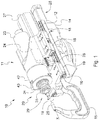
- FIG. 1 there is shown an exemplary embodiment of a working head for industrial robots, e.g. a drilling head 10 according to an embodiment of the present invention, to which reference will be made hereinafter.
- Drilling head 10 also referred to as working head 10 in the present description, includes: a spindle 11, for instance an electrically operated spindle, which is slidably mounted on a head support 14; a worm screw 26, connected to spindle 11 and arranged to move it in a feed direction X - X; and a counter arm 15, connected to worm screw 26 and slidably mounted on head support 14.
- a spindle 11 for instance an electrically operated spindle, which is slidably mounted on a head support 14
- a worm screw 26 connected to spindle 11 and arranged to move it in a feed direction X - X
- a counter arm 15 connected to worm screw 26 and slidably mounted on head support 14.
- drilling head 10 includes a spindle 11 connected to a working slide 12, a counter arm 15 connected to a counter slide 16 and a head support 14 which can be for instance connected to a robot arm.
- Working slide 12 and counter slide 16 are slidably mounted on head support 14, for instance on drilling guides 18 and counter guides 19, respectively.
- working slide 12 and counter slide 16 are slidable in a feed direction, parallel to the spindle axis and, in the exemplary case of the drilling head, parallel to drilling axis X - X.
- spindle 11 is fastened, for instance screwed, onto working slide 12 and counter arm 15 is fastened, for instance screwed, onto counter slide 16.
- spindle 11 in turn includes a tool 20, for instance a drilling tool with a drilling bit 21, a tool carrier 22 and a spindle motor 23.
- spindle 11 is connected to a spindle support 24, which is in turn connected to working slide 12.
- spindle 11 is fastened, for instance screwed, onto spindle support 24, and spindle support 24 is fastened, for instance screwed, onto working slide 12.
- counter arm 15 includes a bored counter bushing 25, which is located on drilling axis X - X so that tool 20, for instance drilling bit 21, can pass through the bushing.
- counter bushing 25 is connected to one end of counter arm 15.
- worm screw 26 e.g. a ball screw, which is connected to counter slide 16 through a nut 38 and to working slide 12 through a screw support 39.
- Screw 26 is connected to a slide motor 27 and is made to rotate by said slide motor 27, which in turn is connected to working slide 12 so as to be movable integrally with spindle 11.
- Slide motor 27 is fastened, for instance screwed, onto working slide 12.
- ball screw 26 coupled with nut 38 and support 39 is arranged to cause spindle 11 and counter arm 15, and preferably working slide 12 and counter slide 16, to move in the feed direction and in mutually opposite senses.
- screw 26 is made to rotate, nut 38 and support 39 cause working slide 12 and counter slide 16 to move in opposite directions, so as to compress the stack of superimposed panels and structures to be machined between counter arm 15 and tool 20, as it will be disclosed in detail below.
- Working head 10 includes a balancing cylinder 28 connected to spindle 11 and head support 14, and arranged to balance, under the control of a controller, the variation of forces applied to the spindle as its spatial position varies.
- Balancing cylinder 28 is arranged to exert a predetermined force, or threshold force, onto spindle 11, or preferably onto working slide 12 connected to spindle 11, so that the spindle moves when a force exceeding said predetermined force is applied to it.
- balancing cylinder 28 is a pneumatic balancing cylinder, shown in Fig. 2 , and it includes a body 31, connected to head support 14, and a stem 32 movable within body 31 and having one end 33 connected to working slide 12.
- said predetermined force can be controlled by an electronic controller and it is made to vary in known manner by acting onto the pneumatic balancing cylinder.
- body 31 is fastened, for instance screwed, onto head support 14, and end 33 of stem 32 is fastened to working slide 12, for instance, threaded stem end 33 is screwed onto working slide 12.
- tool 20 includes a bushing 29 arranged to internally accommodate drilling bit 21 and provided with an opening through which the bit can come out.
- tool 20 includes a sleeve 42 arranged to internally receive the forward end of spindle motor 23 and provided with a cover 43.
- the working device further includes, in known manner, a fluidic circuit arranged to generate a fluid flow inside bit 21, and a suction circuit formed inside sleeve 42 and performing suction around the bit during working, in order to remove chips, swarfs or materials emitted in the area where the tool is working.
- bushing 29 includes for instance a first tubular segment 36 and a second tubular segment 37 connected together so as to form a telescopic sleeve able to reversibly extend and collapse.
- the second tubular segment 37 is connected, for instance welded, to cover 43.
- a spring 34 for instance a helical spring, by pushing at one end against cover 43 and at the other end against a plate 35 connected to the first tubular segment 36, tends to completely extend the telescopic sleeve.
- plate 35 and cover 43 include seats where the ends of spring 34 are received.
- Bushing 29, when completely extended, is arranged so that it wholly encloses the drilling bit, whereas, when compressed, it allows the bit to project out, thereby permitting working.
- the first tubular segment 36 is formed of three tubular segments with different diameters.
- working head 10 The operation of working head 10 according to the invention is as follows.
- working head 10 is positioned so that the superimposed panels and/or structures to be machined are located between counter arm 15 and tool 20, preferably between counter bushing 25 and tool 20.
- slide motor 27 puts worm screw 26, preferably the ball screw, into rotation, thereby causing counter arm 15 connected thereto, and preferably counter slide 16 connected to counter arm 15 and to worm screw 26, to move.
- balancing cylinder 28 being calibrated with such a force as to oppose the movement of working slide 12 connected thereto, acts so that, when ball screw 26 is made to rotate, counter slide 16 moves, whereas tool 20 and working slide 12 remain stationary.
- counter arm 15 arrives in contact with the stacked panels and/or structures, thereby exerting a compression force thereon.
- a fourth step the movement of tool 20, preferably of working slide 12 connected thereto, which had remained stationary in the second step, begins, said movement continuing as long as tool 20, and preferably bushing 29 thereof, arrives in contact with the panels and/or structures. That fourth step starts when the compression force exerted onto the stacked panels and/or structures during the third step exceeds the force required to cause spindle 11, preferably working slide 12 connected thereto, to move.
- the thrust applied to the stack continues until tool 20 begins the machining, for instance until the thrust exceeds the threshold required to cause return of the first tubular segment 36, by overcoming the thrust exerted by spring 34, thereby allowing the machining to begin.
- working head 10 allows obtaining a working head for industrial robots that has a reduced size and that is suitable for use in order to drill superimposed panels and structures at areas difficult to be accessed.
- the provision of the counter arm allows having a reduced size with respect to the prior art working heads, which require the provision of two opposed heads.
- working head 10 according to the invention has the advantage of having a simple and cheap mechanism for keeping the panels and the structures pressed and stacked during machining.
Landscapes
- Engineering & Computer Science (AREA)
- Mechanical Engineering (AREA)
- Machine Tool Units (AREA)
- Manipulator (AREA)
Claims (8)
- Tête de travail (10) pour des robots industriels, comprenant :- une broche (11) comprenant un outil (20), ladite broche (11) etant raccordee à un coulisseau de travail (12) monte coulissant sur un support de tête (14) ;- une vis sans fin (26) raccordee au coulisseau de travail (12) et agencee pour l'amener à se deplacer dans une direction d'alimentation (X-X) ;- un contre-bras (15) raccorde à un contre-coulisseau (16) raccorde à la vis sans fin (26) et monte coulissant sur le support de tête (14), ledit contre-bras (15) etant agence pour être deplace par ladite vis sans fin (26) dans la direction d'alimentation (X-X) et dans un sens oppose à celui du deplacement de la broche (11), afin de comprimer une pile de panneaux et/ou de structures superpose(e)s à usiner entre le contre-bras (15) et l'outil (20),la tête de travail comprenant en outre un moteur de coulisseau (27) fixe au coulisseau de travail (12) et raccorde à la vis sans fin (26) afin de deplacer le coulisseau de travail (12) et le contre-coulisseau (16), et un verin d'équilibrage (28) raccorde à la broche (11) et au support de tête (14) afin d'équilibrer la variation de forces appliquees à la broche à mesure que sa position spatiale varie.
- Tête de travail (10) selon la revendication 1, dans laquelle le verin d'equilibrage (28) est agence pour exercer une force predeterminee sur la broche (11), de sorte que la broche se deplace lorsqu'une force superieure à ladite force predeterminee est exercee sur elle.
- Tête de travail (10) selon la revendication 1 ou 2, dans laquelle le verin d'équilibrage (28) est un verin d'équilibrage pneumatique et comprend un corps (31) raccorde au support de tête (14), et une tige (32) mobile au sein du corps (31) et ayant une extremite (33) raccordee au coulisseau de travail (12), qui est quant à lui raccorde à la broche (11).
- Tête de travail (10) selon la revendication 2 ou 3, dans laquelle ladite force predeterminee est commandee par un dispositif de commande electronique.
- Tête de travail (10) selon l'une quelconque des revendications precedentes, dans laquelle l'outil (20) est un outil de forage comprenant un foret (21).
- Tête de travail (10) selon la revendication 5, dans laquelle le contre-bras (15) comprend une contre-douille alésée (25) situee selon l'axe de forage (X-X) et agencee pour être traversee par le foret (21).
- Tête de travail (10) selon l'une quelconque des revendications precedentes, dans laquelle l'outil (20) comprend une douille (29) agencee pour loger à l'interieur le foret (21) et pourvue d'une ouverture à travers laquelle le foret peut sortir, ladite douille (29) comprenant en outre un premier segment tubulaire (36) et un second segment tubulaire (37) raccordes ensemble de façon à former un manchon telescopique capable de s'étendre et se rabattre de façon reversible.
- Procede d'usinage de panneaux et/ou de structures superpose(e)s, comprenant les etapes suivantes :- la fourniture d'une tête de travail (10) selon l'une quelconque des revendications precedentes ;- le placement de la tête de travail (10) de sorte que les panneaux et/ou structures superpose(e)s à usiner soient situes entre le contre-bras (15) et l'outil (20) ;- la mise en rotation de la vis sans fin (26), déplaçant ainsi le contre-bras (15) raccorde à celle-ci jusqu'à ce qu'il arrive en contact avec les panneaux et/ou structures superposé(e)s, tandis que l'outil (20) est maintenu immobile ;- le fait d'exercer une force de compression sur les panneaux et/ou structures superpose(e)s au moyen du contre-bras (15), appliquant ainsi une force de compression à ceux-ci ;- le deplacement de l'outil (20) jusqu'à ce qu'il arrive en contact avec les panneaux et/ou les structures ;- le maintien de la poussee exercee sur la pile de panneaux et/ou de structures jusqu'à ce que l'outil (20) commence à travailler.
Applications Claiming Priority (2)
| Application Number | Priority Date | Filing Date | Title |
|---|---|---|---|
| ITTO20140950 | 2014-11-17 | ||
| PCT/IB2015/058548 WO2016079628A1 (en) | 2014-11-17 | 2015-11-05 | Device and method for mechanical working |
Publications (2)
| Publication Number | Publication Date |
|---|---|
| EP3221069A1 EP3221069A1 (de) | 2017-09-27 |
| EP3221069B1 true EP3221069B1 (de) | 2019-07-17 |
Family
ID=52355093
Family Applications (1)
| Application Number | Title | Priority Date | Filing Date |
|---|---|---|---|
| EP15823192.8A Not-in-force EP3221069B1 (de) | 2014-11-17 | 2015-11-05 | Vorrichtung und verfahren zur mechanischen bearbeitung |
Country Status (4)
| Country | Link |
|---|---|
| EP (1) | EP3221069B1 (de) |
| CN (1) | CN107000032B (de) |
| ES (1) | ES2750558T3 (de) |
| WO (1) | WO2016079628A1 (de) |
Families Citing this family (3)
| Publication number | Priority date | Publication date | Assignee | Title |
|---|---|---|---|---|
| CN112958743B (zh) * | 2021-03-30 | 2022-09-30 | 杭州艾美依航空制造装备有限公司 | 一种驱动复用自动钻铆机的压铆驱动装置 |
| CN115805522A (zh) * | 2022-12-21 | 2023-03-17 | 江门杰能刀剪装备科技有限公司 | 一种伸缩机械手及上下料装置 |
| IT202300010311A1 (it) * | 2023-05-22 | 2024-11-22 | Francesco Luzzi | Macchinario, kit e sistema per la ribaditura di rivetti |
Family Cites Families (10)
| Publication number | Priority date | Publication date | Assignee | Title |
|---|---|---|---|---|
| US3111869A (en) * | 1961-12-04 | 1963-11-26 | Acf Ind Inc | Portable punch riveter |
| DE3232093C2 (de) * | 1982-08-28 | 1987-03-26 | Messerschmitt-Bölkow-Blohm GmbH, 8012 Ottobrunn | Automatische Nietmaschine |
| FR2618706B1 (fr) * | 1987-07-29 | 1989-12-22 | Recoules & Fils Ets | Dispositif de percage et rivetage |
| US5169047A (en) * | 1991-10-30 | 1992-12-08 | Endres Thomas E | Compact rivet attachment apparatus |
| JP3742297B2 (ja) * | 2000-12-26 | 2006-02-01 | 福井鋲螺株式会社 | イコライズ機構付きポータブル型リベットかしめ機 |
| ITPD20060002A1 (it) * | 2006-01-03 | 2007-07-04 | Lg Technologies Srl | Dispositivo per la foratura |
| ITTO20060581A1 (it) | 2006-08-04 | 2008-02-05 | Bruno Bisiach | Dispositivo e metodo di lavorazione di un pezzo da lavorare, quale per esempio una struttura a guscio di un velivolo |
| FR2909572B1 (fr) * | 2006-12-07 | 2009-02-13 | Latecis Soc Par Actions Simpli | Machine de pose d'organes de fixation de type rivet, notamment pour pieces de fuselage ou de sous-ensembles d'aeronefs. |
| CN101856730B (zh) * | 2010-06-01 | 2012-04-04 | 山东法因数控机械股份有限公司 | 一种复合动力头装置 |
| CN102794491B (zh) * | 2012-08-22 | 2014-05-07 | 浙江大学 | 一种自动化螺旋铣孔装置及其方法 |
-
2015
- 2015-11-05 EP EP15823192.8A patent/EP3221069B1/de not_active Not-in-force
- 2015-11-05 ES ES15823192T patent/ES2750558T3/es active Active
- 2015-11-05 CN CN201580062133.4A patent/CN107000032B/zh not_active Expired - Fee Related
- 2015-11-05 WO PCT/IB2015/058548 patent/WO2016079628A1/en not_active Ceased
Non-Patent Citations (1)
| Title |
|---|
| None * |
Also Published As
| Publication number | Publication date |
|---|---|
| WO2016079628A1 (en) | 2016-05-26 |
| EP3221069A1 (de) | 2017-09-27 |
| CN107000032A (zh) | 2017-08-01 |
| ES2750558T3 (es) | 2020-03-26 |
| CN107000032B (zh) | 2019-03-29 |
Similar Documents
| Publication | Publication Date | Title |
|---|---|---|
| US9061419B2 (en) | Processing tool and processing method | |
| US10010928B2 (en) | Device for connecting structural components, in particularly by means of direct screwing, especially flow hole screwing, or by means of friction welding, and method for connecting structural components, in particular by means of direct screwing or friction welding | |
| EP3221069B1 (de) | Vorrichtung und verfahren zur mechanischen bearbeitung | |
| US5062746A (en) | Clamping attachment for portable drills | |
| US20170066059A1 (en) | Cnc turning and milling machine | |
| CN107096935A (zh) | 环形工件加工夹具 | |
| KR20160090499A (ko) | 클램핑 장치 | |
| EP1499473B1 (de) | Konzentrische, pneumatisch/hydraulisch angetriebene vorschubeinrichtung | |
| EP3871837B1 (de) | Automatisiertes intelligentes schraubstocksystem | |
| CN206677601U (zh) | 工件定位装置以及工件钻孔设备 | |
| JP5009838B2 (ja) | ワークの支持装置および回転割出機 | |
| US4565476A (en) | Internal hydraulic clamp | |
| WO2019008132A1 (en) | MACHINING ARRANGEMENT AND METHOD FOR FASTENING A WORKPIECE FOR MACHINING AND MACHINING A WORKPIECE | |
| US4688321A (en) | Method for securing a workpiece to a fixture | |
| JP2005052935A (ja) | 心押装置 | |
| US11931839B2 (en) | Transfer machine | |
| JP5570871B2 (ja) | 加工装置 | |
| KR101746093B1 (ko) | 공구어댑터 및 이를 이용한 드릴장치 | |
| CN211029020U (zh) | 一种数控机床轴向可调式定位装置 | |
| CN104802024A (zh) | 用于棒材进给系统的棒材导向单元 | |
| CN112139531B (zh) | 一种用于金属块的打孔装置 | |
| JP3125876U (ja) | 空圧進退駆動型電動加工装置 | |
| CN202527790U (zh) | 桶体内壁加工刀具 | |
| CN213890005U (zh) | 一种可扩展式移动机器人 | |
| KR20170000489A (ko) | 터닝 센터의 트윈 척용 커버 장치 |
Legal Events
| Date | Code | Title | Description |
|---|---|---|---|
| STAA | Information on the status of an ep patent application or granted ep patent |
Free format text: STATUS: THE INTERNATIONAL PUBLICATION HAS BEEN MADE |
|
| PUAI | Public reference made under article 153(3) epc to a published international application that has entered the european phase |
Free format text: ORIGINAL CODE: 0009012 |
|
| STAA | Information on the status of an ep patent application or granted ep patent |
Free format text: STATUS: REQUEST FOR EXAMINATION WAS MADE |
|
| 17P | Request for examination filed |
Effective date: 20170516 |
|
| AK | Designated contracting states |
Kind code of ref document: A1 Designated state(s): AL AT BE BG CH CY CZ DE DK EE ES FI FR GB GR HR HU IE IS IT LI LT LU LV MC MK MT NL NO PL PT RO RS SE SI SK SM TR |
|
| AX | Request for extension of the european patent |
Extension state: BA ME |
|
| DAV | Request for validation of the european patent (deleted) | ||
| DAX | Request for extension of the european patent (deleted) | ||
| GRAP | Despatch of communication of intention to grant a patent |
Free format text: ORIGINAL CODE: EPIDOSNIGR1 |
|
| STAA | Information on the status of an ep patent application or granted ep patent |
Free format text: STATUS: GRANT OF PATENT IS INTENDED |
|
| INTG | Intention to grant announced |
Effective date: 20190221 |
|
| GRAS | Grant fee paid |
Free format text: ORIGINAL CODE: EPIDOSNIGR3 |
|
| GRAA | (expected) grant |
Free format text: ORIGINAL CODE: 0009210 |
|
| STAA | Information on the status of an ep patent application or granted ep patent |
Free format text: STATUS: THE PATENT HAS BEEN GRANTED |
|
| AK | Designated contracting states |
Kind code of ref document: B1 Designated state(s): AL AT BE BG CH CY CZ DE DK EE ES FI FR GB GR HR HU IE IS IT LI LT LU LV MC MK MT NL NO PL PT RO RS SE SI SK SM TR |
|
| REG | Reference to a national code |
Ref country code: GB Ref legal event code: FG4D |
|
| REG | Reference to a national code |
Ref country code: CH Ref legal event code: EP |
|
| REG | Reference to a national code |
Ref country code: DE Ref legal event code: R096 Ref document number: 602015034027 Country of ref document: DE |
|
| REG | Reference to a national code |
Ref country code: IE Ref legal event code: FG4D |
|
| REG | Reference to a national code |
Ref country code: AT Ref legal event code: REF Ref document number: 1155374 Country of ref document: AT Kind code of ref document: T Effective date: 20190815 |
|
| REG | Reference to a national code |
Ref country code: NL Ref legal event code: MP Effective date: 20190717 |
|
| REG | Reference to a national code |
Ref country code: LT Ref legal event code: MG4D |
|
| REG | Reference to a national code |
Ref country code: AT Ref legal event code: MK05 Ref document number: 1155374 Country of ref document: AT Kind code of ref document: T Effective date: 20190717 |
|
| PG25 | Lapsed in a contracting state [announced via postgrant information from national office to epo] |
Ref country code: BG Free format text: LAPSE BECAUSE OF FAILURE TO SUBMIT A TRANSLATION OF THE DESCRIPTION OR TO PAY THE FEE WITHIN THE PRESCRIBED TIME-LIMIT Effective date: 20191017 Ref country code: NL Free format text: LAPSE BECAUSE OF FAILURE TO SUBMIT A TRANSLATION OF THE DESCRIPTION OR TO PAY THE FEE WITHIN THE PRESCRIBED TIME-LIMIT Effective date: 20190717 Ref country code: LT Free format text: LAPSE BECAUSE OF FAILURE TO SUBMIT A TRANSLATION OF THE DESCRIPTION OR TO PAY THE FEE WITHIN THE PRESCRIBED TIME-LIMIT Effective date: 20190717 Ref country code: PT Free format text: LAPSE BECAUSE OF FAILURE TO SUBMIT A TRANSLATION OF THE DESCRIPTION OR TO PAY THE FEE WITHIN THE PRESCRIBED TIME-LIMIT Effective date: 20191118 Ref country code: AT Free format text: LAPSE BECAUSE OF FAILURE TO SUBMIT A TRANSLATION OF THE DESCRIPTION OR TO PAY THE FEE WITHIN THE PRESCRIBED TIME-LIMIT Effective date: 20190717 Ref country code: HR Free format text: LAPSE BECAUSE OF FAILURE TO SUBMIT A TRANSLATION OF THE DESCRIPTION OR TO PAY THE FEE WITHIN THE PRESCRIBED TIME-LIMIT Effective date: 20190717 Ref country code: SE Free format text: LAPSE BECAUSE OF FAILURE TO SUBMIT A TRANSLATION OF THE DESCRIPTION OR TO PAY THE FEE WITHIN THE PRESCRIBED TIME-LIMIT Effective date: 20190717 Ref country code: NO Free format text: LAPSE BECAUSE OF FAILURE TO SUBMIT A TRANSLATION OF THE DESCRIPTION OR TO PAY THE FEE WITHIN THE PRESCRIBED TIME-LIMIT Effective date: 20191017 Ref country code: FI Free format text: LAPSE BECAUSE OF FAILURE TO SUBMIT A TRANSLATION OF THE DESCRIPTION OR TO PAY THE FEE WITHIN THE PRESCRIBED TIME-LIMIT Effective date: 20190717 |
|
| PG25 | Lapsed in a contracting state [announced via postgrant information from national office to epo] |
Ref country code: IS Free format text: LAPSE BECAUSE OF FAILURE TO SUBMIT A TRANSLATION OF THE DESCRIPTION OR TO PAY THE FEE WITHIN THE PRESCRIBED TIME-LIMIT Effective date: 20191117 Ref country code: RS Free format text: LAPSE BECAUSE OF FAILURE TO SUBMIT A TRANSLATION OF THE DESCRIPTION OR TO PAY THE FEE WITHIN THE PRESCRIBED TIME-LIMIT Effective date: 20190717 Ref country code: GR Free format text: LAPSE BECAUSE OF FAILURE TO SUBMIT A TRANSLATION OF THE DESCRIPTION OR TO PAY THE FEE WITHIN THE PRESCRIBED TIME-LIMIT Effective date: 20191018 Ref country code: AL Free format text: LAPSE BECAUSE OF FAILURE TO SUBMIT A TRANSLATION OF THE DESCRIPTION OR TO PAY THE FEE WITHIN THE PRESCRIBED TIME-LIMIT Effective date: 20190717 Ref country code: LV Free format text: LAPSE BECAUSE OF FAILURE TO SUBMIT A TRANSLATION OF THE DESCRIPTION OR TO PAY THE FEE WITHIN THE PRESCRIBED TIME-LIMIT Effective date: 20190717 |
|
| REG | Reference to a national code |
Ref country code: ES Ref legal event code: FG2A Ref document number: 2750558 Country of ref document: ES Kind code of ref document: T3 Effective date: 20200326 |
|
| PG25 | Lapsed in a contracting state [announced via postgrant information from national office to epo] |
Ref country code: TR Free format text: LAPSE BECAUSE OF FAILURE TO SUBMIT A TRANSLATION OF THE DESCRIPTION OR TO PAY THE FEE WITHIN THE PRESCRIBED TIME-LIMIT Effective date: 20190717 |
|
| PG25 | Lapsed in a contracting state [announced via postgrant information from national office to epo] |
Ref country code: RO Free format text: LAPSE BECAUSE OF FAILURE TO SUBMIT A TRANSLATION OF THE DESCRIPTION OR TO PAY THE FEE WITHIN THE PRESCRIBED TIME-LIMIT Effective date: 20190717 Ref country code: EE Free format text: LAPSE BECAUSE OF FAILURE TO SUBMIT A TRANSLATION OF THE DESCRIPTION OR TO PAY THE FEE WITHIN THE PRESCRIBED TIME-LIMIT Effective date: 20190717 Ref country code: DK Free format text: LAPSE BECAUSE OF FAILURE TO SUBMIT A TRANSLATION OF THE DESCRIPTION OR TO PAY THE FEE WITHIN THE PRESCRIBED TIME-LIMIT Effective date: 20190717 Ref country code: PL Free format text: LAPSE BECAUSE OF FAILURE TO SUBMIT A TRANSLATION OF THE DESCRIPTION OR TO PAY THE FEE WITHIN THE PRESCRIBED TIME-LIMIT Effective date: 20190717 |
|
| PG25 | Lapsed in a contracting state [announced via postgrant information from national office to epo] |
Ref country code: CZ Free format text: LAPSE BECAUSE OF FAILURE TO SUBMIT A TRANSLATION OF THE DESCRIPTION OR TO PAY THE FEE WITHIN THE PRESCRIBED TIME-LIMIT Effective date: 20190717 Ref country code: SK Free format text: LAPSE BECAUSE OF FAILURE TO SUBMIT A TRANSLATION OF THE DESCRIPTION OR TO PAY THE FEE WITHIN THE PRESCRIBED TIME-LIMIT Effective date: 20190717 Ref country code: SM Free format text: LAPSE BECAUSE OF FAILURE TO SUBMIT A TRANSLATION OF THE DESCRIPTION OR TO PAY THE FEE WITHIN THE PRESCRIBED TIME-LIMIT Effective date: 20190717 Ref country code: IS Free format text: LAPSE BECAUSE OF FAILURE TO SUBMIT A TRANSLATION OF THE DESCRIPTION OR TO PAY THE FEE WITHIN THE PRESCRIBED TIME-LIMIT Effective date: 20200224 |
|
| REG | Reference to a national code |
Ref country code: DE Ref legal event code: R097 Ref document number: 602015034027 Country of ref document: DE |
|
| REG | Reference to a national code |
Ref country code: CH Ref legal event code: PL |
|
| PLBE | No opposition filed within time limit |
Free format text: ORIGINAL CODE: 0009261 |
|
| STAA | Information on the status of an ep patent application or granted ep patent |
Free format text: STATUS: NO OPPOSITION FILED WITHIN TIME LIMIT |
|
| PG2D | Information on lapse in contracting state deleted |
Ref country code: IS |
|
| PG25 | Lapsed in a contracting state [announced via postgrant information from national office to epo] |
Ref country code: LI Free format text: LAPSE BECAUSE OF NON-PAYMENT OF DUE FEES Effective date: 20191130 Ref country code: LU Free format text: LAPSE BECAUSE OF NON-PAYMENT OF DUE FEES Effective date: 20191105 Ref country code: CH Free format text: LAPSE BECAUSE OF NON-PAYMENT OF DUE FEES Effective date: 20191130 Ref country code: MC Free format text: LAPSE BECAUSE OF FAILURE TO SUBMIT A TRANSLATION OF THE DESCRIPTION OR TO PAY THE FEE WITHIN THE PRESCRIBED TIME-LIMIT Effective date: 20190717 |
|
| 26N | No opposition filed |
Effective date: 20200603 |
|
| REG | Reference to a national code |
Ref country code: BE Ref legal event code: MM Effective date: 20191130 |
|
| PG25 | Lapsed in a contracting state [announced via postgrant information from national office to epo] |
Ref country code: SI Free format text: LAPSE BECAUSE OF FAILURE TO SUBMIT A TRANSLATION OF THE DESCRIPTION OR TO PAY THE FEE WITHIN THE PRESCRIBED TIME-LIMIT Effective date: 20190717 |
|
| PG25 | Lapsed in a contracting state [announced via postgrant information from national office to epo] |
Ref country code: BE Free format text: LAPSE BECAUSE OF NON-PAYMENT OF DUE FEES Effective date: 20191130 |
|
| PG25 | Lapsed in a contracting state [announced via postgrant information from national office to epo] |
Ref country code: CY Free format text: LAPSE BECAUSE OF FAILURE TO SUBMIT A TRANSLATION OF THE DESCRIPTION OR TO PAY THE FEE WITHIN THE PRESCRIBED TIME-LIMIT Effective date: 20190717 |
|
| PG25 | Lapsed in a contracting state [announced via postgrant information from national office to epo] |
Ref country code: MT Free format text: LAPSE BECAUSE OF FAILURE TO SUBMIT A TRANSLATION OF THE DESCRIPTION OR TO PAY THE FEE WITHIN THE PRESCRIBED TIME-LIMIT Effective date: 20190717 Ref country code: HU Free format text: LAPSE BECAUSE OF FAILURE TO SUBMIT A TRANSLATION OF THE DESCRIPTION OR TO PAY THE FEE WITHIN THE PRESCRIBED TIME-LIMIT; INVALID AB INITIO Effective date: 20151105 |
|
| PG25 | Lapsed in a contracting state [announced via postgrant information from national office to epo] |
Ref country code: MK Free format text: LAPSE BECAUSE OF FAILURE TO SUBMIT A TRANSLATION OF THE DESCRIPTION OR TO PAY THE FEE WITHIN THE PRESCRIBED TIME-LIMIT Effective date: 20190717 |
|
| PGFP | Annual fee paid to national office [announced via postgrant information from national office to epo] |
Ref country code: GB Payment date: 20231129 Year of fee payment: 9 |
|
| PGFP | Annual fee paid to national office [announced via postgrant information from national office to epo] |
Ref country code: ES Payment date: 20231204 Year of fee payment: 9 |
|
| PGFP | Annual fee paid to national office [announced via postgrant information from national office to epo] |
Ref country code: IT Payment date: 20231124 Year of fee payment: 9 Ref country code: IE Payment date: 20231130 Year of fee payment: 9 Ref country code: FR Payment date: 20231120 Year of fee payment: 9 Ref country code: DE Payment date: 20231120 Year of fee payment: 9 |
|
| REG | Reference to a national code |
Ref country code: DE Ref legal event code: R119 Ref document number: 602015034027 Country of ref document: DE |
|
| GBPC | Gb: european patent ceased through non-payment of renewal fee |
Effective date: 20241105 |
|
| PG25 | Lapsed in a contracting state [announced via postgrant information from national office to epo] |
Ref country code: DE Free format text: LAPSE BECAUSE OF NON-PAYMENT OF DUE FEES Effective date: 20250603 |
|
| PG25 | Lapsed in a contracting state [announced via postgrant information from national office to epo] |
Ref country code: IT Free format text: LAPSE BECAUSE OF NON-PAYMENT OF DUE FEES Effective date: 20241105 |
|
| PG25 | Lapsed in a contracting state [announced via postgrant information from national office to epo] |
Ref country code: GB Free format text: LAPSE BECAUSE OF NON-PAYMENT OF DUE FEES Effective date: 20241105 |
|
| PG25 | Lapsed in a contracting state [announced via postgrant information from national office to epo] |
Ref country code: FR Free format text: LAPSE BECAUSE OF NON-PAYMENT OF DUE FEES Effective date: 20241130 |
|
| PG25 | Lapsed in a contracting state [announced via postgrant information from national office to epo] |
Ref country code: IE Free format text: LAPSE BECAUSE OF NON-PAYMENT OF DUE FEES Effective date: 20241105 |
|
| REG | Reference to a national code |
Ref country code: ES Ref legal event code: FD2A Effective date: 20251230 |
|
| PG25 | Lapsed in a contracting state [announced via postgrant information from national office to epo] |
Ref country code: ES Free format text: LAPSE BECAUSE OF NON-PAYMENT OF DUE FEES Effective date: 20241106 |