EP3215745B1 - Schutzgitter mit verbessertem wirkungsgrad- und geräuschverhalten - Google Patents
Schutzgitter mit verbessertem wirkungsgrad- und geräuschverhalten Download PDFInfo
- Publication number
- EP3215745B1 EP3215745B1 EP15745489.3A EP15745489A EP3215745B1 EP 3215745 B1 EP3215745 B1 EP 3215745B1 EP 15745489 A EP15745489 A EP 15745489A EP 3215745 B1 EP3215745 B1 EP 3215745B1
- Authority
- EP
- European Patent Office
- Prior art keywords
- protective grille
- radial
- webs
- protective
- axial
- Prior art date
- Legal status (The legal status is an assumption and is not a legal conclusion. Google has not performed a legal analysis and makes no representation as to the accuracy of the status listed.)
- Active
Links
Images


Classifications
-
- F—MECHANICAL ENGINEERING; LIGHTING; HEATING; WEAPONS; BLASTING
- F04—POSITIVE - DISPLACEMENT MACHINES FOR LIQUIDS; PUMPS FOR LIQUIDS OR ELASTIC FLUIDS
- F04D—NON-POSITIVE-DISPLACEMENT PUMPS
- F04D29/00—Details, component parts, or accessories
- F04D29/70—Suction grids; Strainers; Dust separation; Cleaning
- F04D29/701—Suction grids; Strainers; Dust separation; Cleaning especially adapted for elastic fluid pumps
- F04D29/703—Suction grids; Strainers; Dust separation; Cleaning especially adapted for elastic fluid pumps specially for fans, e.g. fan guards
-
- F—MECHANICAL ENGINEERING; LIGHTING; HEATING; WEAPONS; BLASTING
- F04—POSITIVE - DISPLACEMENT MACHINES FOR LIQUIDS; PUMPS FOR LIQUIDS OR ELASTIC FLUIDS
- F04D—NON-POSITIVE-DISPLACEMENT PUMPS
- F04D29/00—Details, component parts, or accessories
- F04D29/40—Casings; Connections of working fluid
- F04D29/52—Casings; Connections of working fluid for axial pumps
- F04D29/54—Fluid-guiding means, e.g. diffusers
- F04D29/541—Specially adapted for elastic fluid pumps
-
- F—MECHANICAL ENGINEERING; LIGHTING; HEATING; WEAPONS; BLASTING
- F24—HEATING; RANGES; VENTILATING
- F24F—AIR-CONDITIONING; AIR-HUMIDIFICATION; VENTILATION; USE OF AIR CURRENTS FOR SCREENING
- F24F13/00—Details common to, or for air-conditioning, air-humidification, ventilation or use of air currents for screening
- F24F13/08—Air-flow control members, e.g. louvres, grilles, flaps or guide plates
- F24F13/082—Grilles, registers or guards
-
- F—MECHANICAL ENGINEERING; LIGHTING; HEATING; WEAPONS; BLASTING
- F04—POSITIVE - DISPLACEMENT MACHINES FOR LIQUIDS; PUMPS FOR LIQUIDS OR ELASTIC FLUIDS
- F04D—NON-POSITIVE-DISPLACEMENT PUMPS
- F04D19/00—Axial-flow pumps
- F04D19/002—Axial flow fans
-
- F—MECHANICAL ENGINEERING; LIGHTING; HEATING; WEAPONS; BLASTING
- F24—HEATING; RANGES; VENTILATING
- F24F—AIR-CONDITIONING; AIR-HUMIDIFICATION; VENTILATION; USE OF AIR CURRENTS FOR SCREENING
- F24F13/00—Details common to, or for air-conditioning, air-humidification, ventilation or use of air currents for screening
- F24F13/08—Air-flow control members, e.g. louvres, grilles, flaps or guide plates
- F24F13/082—Grilles, registers or guards
- F24F2013/088—Air-flow straightener
Definitions
- the invention relates to protective grilles as protection against accidental contact for the suction side of fans, for example radial fans or diagonal fans, the protective grilles having a planar grating web structure formed from radial webs spaced in the circumferential direction and coaxial circumferential webs spaced in the radial direction.
- a protective grille is out WO 03/054395 A1 known.
- the document WO 2015/1247237 A1 also shows a protective grille.
- This document falls under Art. 54 (3) EPC and is therefore of no importance for the question of inventive step.
- Plastic or metal with relatively thick walls is usually used as the material in order to ensure sufficient stability.
- the disadvantage here is that when the air is sucked in through the protective grille, the overall static efficiency of the fan with the protective grille arranged thereon deteriorates and the sound power increases significantly, in particular at higher volume flows.
- the invention is therefore based on the object of providing a protective grille for fans which, when attached to fans, ensures improved overall static efficiency and reduced sound power compared to conventional protective grilles.
- an at least partially three-dimensionally curved protective grille with fastening means for arrangement on a fan is proposed, the axial central region of which, however, is further spaced apart from the fan and thus the fan wheel due to the at least partially convex shape.
- the protective grid has a grid web structure which comprises radial webs which are spaced apart in the circumferential direction and coaxial circumferential webs which are spaced apart in the radial direction, the protective grid having at least one radial outer region and a central region around a central axis of the protective grid, an enveloping surface spanned by the radial outer region and the central region in the radial direction Outside area is convexly curved and flat in the central area, in particular parallel to a radial plane of the protective grille.
- the curved shape of the protective grille which is produced by the radial outer region provided with a convex envelope surface, increases its strength and stability and makes it possible to make the radial webs and peripheral webs thinner in cross-section. This reduces the flow area of the webs, the flow resistance generated by the webs and the eddy formation caused by the webs, which in turn leads to noise formation.
- the radial webs and / or the circumferential webs have a rectangular cross section with a height H and a wall thickness B, the ratio of which to H / W ⁇ 3, in particular H / W ⁇ 3.5, more preferably H / W ⁇ 4 is set.
- the side of the radial and circumferential webs which determines the wall thickness B points in one direction or counter to the flow direction, which in the central region is at least essentially in an axial direction corresponds to the protective grille.
- the protective grid is preferably rotationally symmetrical.
- the central region directly adjoins the radial outer region in the radial direction, the convexly curved envelope surface of the radial outer region flowing smoothly into the flat central region.
- This uninterrupted design of the protective grille along its envelope surface also favors strength and stability and promotes the possibility of making the radial and circumferential webs thinner as previously described.
- an intermediate area can be provided between the radial axial area and the central area, the envelope surface of which has a smaller convex curvature than the radial outer area, but is not designed to be flat.
- the circumferential webs arranged in the radial direction at a radial distance r from the axial center of the protective grille each have a varying angular position with respect to an axial plane of the protective grille.
- the angular position of the circumferential webs increases in the radially outward direction of the protective grille.
- the angle is measured between an extent of the circumferential webs along their height direction (height H) and the axial plane of the protective grille.
- the increasing angle of the circumferential webs from the central area in the direction of the radial outer area also contributes to noise reduction and an improved efficiency of the connected fan.
- the radial webs each have a curved shape in an axial cross section and extend in an arc shape with an arcuate belly pointing to the axial center line of the protective grid.
- the convexly curved envelope surface in the radial outer region determines a partially elliptical contour in a lateral cross section and is characterized in that the ratio of the radial length a of the outer region to the radius c of the protective grid is fixed at a / c> 0.25 . This results in a radial extension of the radial outer region of at least 25% of the total radius of the protective grille.
- a ratio of the axial height b of the protective grille to the radius c of the protective grille is fixed at b / c> 0.02. It is further preferred that the ratio of the axial height b of the protective grille to the radius c of the protective grille is in a range of 0.025 b b / c 1 1, so that a sufficient axial distance to the connected fan or its fan wheel is ensured and at the same time optimized protective grille is provided in terms of noise and efficiency.
- the radial webs extend radially or axially beyond the outermost of the circumferential webs and form an outer edge of the protective grille which is thereby designed to be open to flow. Since the protective grille in the outermost radial outer region extends almost exclusively in the axial direction, the main part lies in an axial extension of the radial webs over the radially outermost circumferential web.
- the fastening means are integrally formed on the protective grille on the radial outer edge of the protective grille in order to enable connection to the fan via the fastening elements customary in the prior art.
- the protective grille is designed in such a way that the number of radial webs in the radial outer region is higher than in the central region in order to make the flow resistance in the central region as low as possible. Due to the overall curved shape of the protective grille and the associated increased axial distance of the central area from the connected fan or fan wheel, the mesh width of the grating web structure can be increased there. According to the invention, this is done by reducing the number of radial webs provided in the central area, i.e. their number decreases in the direction of an axial center of the protective grille.
- the invention further comprises the unit formed from a fan with a protective grille as described above, the efficiency of which is improved and the sound power reduced.
- FIG. 1 An embodiment of a rotationally symmetrical protective grille 1 is shown in a perspective view.
- the protective grid 1 has a grid web structure, formed from intersecting radial webs 2 running at a distance in the circumferential direction and coaxial circumferential webs 3 running at a distance in the radial direction.
- the radial webs 2 extend radially and axially beyond the outermost circumferential web 3 and form a radial one running in the circumferential direction Outer edge.
- four fastening webs 4 are formed in one piece in the circumferential direction, each spaced apart by 90 degrees.
- the fastening webs 4 are themselves partially formed from radial webs 2.
- FIG 2 shows the protective grille 1 Figure 1 in a side view.
- the protective grille 1 has a circumferential radial outer region A and a central region Z around the central axis M.
- An envelope surface spanned by the radial outer region A and the central region Z is convexly curved in the radial outer region A and flat and flat in the central region Z, so that the central region Z extends parallel to a radial plane X of the protective grille 1.
- the central region Z directly adjoins the radial outer region A in the radial inward direction. The transition is fluid.
- the number of radial webs 2 is higher than in the central region Z. This is achieved in that the radial webs 2 extend to different lengths in the radial inward direction and partially no longer reach the radially inner circumferential webs 2. This increases the clear mesh size within the lattice web structure in the central area Z, which at the same time reduces the flow resistance.
- the plurality of circumferential webs 3 is arranged in the radial direction of the protective grille 1 at a radial distance r from the axial center of the protective grille 1.
- An example is in Figure 2 a distance r of the fifth of seven circumferential webs 3 starting from the axial central axis M marked. The distance of the radially outermost circumferential web 3 is marked with R.
- the convexly curved envelope surface of the protective grille 1 can be specified in more detail.
- the convexly curved envelope surface defines, in a lateral cross section, a partially elliptical contour 5, the ratio of the radial length a of the radial outer region A to the radius c of the protective grille 1 in the embodiment shown assumes an exemplary value of approximately 0.55.
- an exemplary value of 0.35 is defined in the embodiment shown.
- Figure 5 shows an example of an alternative embodiment of a partially elliptical contour 5 of the envelope surface with a stronger convex curvature of the radial outer region A and ratios a / c of over 0.6 and b / c of over 0.4.
- Figure 3 shows a side sectional view of the protective grille Figure 1 with a section through a radial web 2.
- the angular position of the circumferential webs 3 can be clearly seen.
- the thin-walled design of the radial webs 2 and circumferential webs 3 is shown, the wall thickness B and height H being identified using radial webs 2. However, this can be applied accordingly to the circumferential webs 3.
- both the radial webs 2 and the circumferential webs 3 are rectangular.
- the ratio of wall thickness B to height H is 5 in the embodiment shown.
- the thin-walled design of the webs 2, 3 is due to the shape of the protective grille 1 enables.
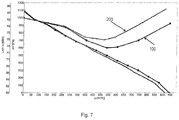
- the Figures 6 and 7 show diagrams of characteristic curve comparisons of the overall static efficiency ( Fig. 6 ) and the sound power ( Fig. 7 ) at different volume flows through the protective grille 1 Fig. 1 and through conventional flat guards.
- the characteristic curves of the protective grille 1 according to the invention are identified by 100, those of the conventional protective grille by 200.
- the fan used is always the same.
- the overall static efficiency of the protective grille 1 according to the invention continues to rise sharply at a volume flow of 400 m 3 / h and thereby produces a difference of over 2% which is maintained up to the maximum volume flow.
- the difference in sound power is also evident from a volume flow of 400 m 3 / h, the protective grille 1 according to the invention being quieter than conventional protective grilles at the maximum volume flow by more than 4 dBA.
- the values measured for the protective grille 1 according to the invention are on a level with values of fan operation without any protective grille.
Landscapes
- Engineering & Computer Science (AREA)
- Mechanical Engineering (AREA)
- General Engineering & Computer Science (AREA)
- Chemical & Material Sciences (AREA)
- Combustion & Propulsion (AREA)
- Structures Of Non-Positive Displacement Pumps (AREA)
Description
- Die Erfindung betrifft Schutzgitter als Berührschutz für die Saugseite von Ventilatoren, beispielsweise Radialventilatoren oder Diagonalventilatoren, wobei die Schutzgitter eine ebene Gitterstegstruktur gebildet aus in Umfangsrichtung beabstandeten Radialstegen und in radialer Richtung beabstandeten koaxialen Umfangsstegen aufweisen. Ein solches Schutzgitter ist aus
WO 03/054395 A1 WO 2015/1247237 A1 - Dabei ist nachteilig, dass sich bei der Ansaugung der Luft durch das Schutzgitter der statische Gesamtwirkungsgrad des Ventilators mit daran angeordnetem Schutzgitter verschlechtert und die Schallleistung insbesondere bei höheren Volumenströmen deutlich erhöht.
- Der Erfindung liegt deshalb die Aufgabe zugrunde, ein Schutzgitter für Ventilatoren bereit zu stellen, das an Ventilatoren befestigt gegenüber herkömmlichen Schutzgittern einen verbesserten statischen Gesamtwirkungsgrad sowie eine reduzierte Schallleistung gewährleistet.
- Diese Aufgabe wird durch ein Schutzgitter mit der Merkmalskombination gemäß Patentanspruch 1 gelöst.
- Dabei wird erfindungsgemäß ein zumindest abschnittsweise dreidimensional in axialer Richtung gekrümmtes Schutzgitter mit Befestigungsmitteln zur Anordnung an einem Ventilator vorgeschlagen, dessen axialer Zentralbereich jedoch durch die zumindest abschnittsweise konvexe Form weiter von dem Ventilator und somit dem Ventilatorrad beabstandet ist. Das Schutzgitter weist eine Gitterstegstruktur auf, die in Umfangsrichtung beabstandete Radialstege und in radialer Richtung beabstandete koaxiale Umfangsstege umfasst, wobei das Schutzgitter zumindest einen radialen Außenbereich und einen Zentralbereich um eine Mittelachse des Schutzgitters aufweist, eine von dem radialen Außenbereich und dem Zentralbereich aufgespannte Hüllfläche im radialen Außenbereich konvex gekrümmt und im Zentralbereich flach, insbesondere parallel zu einer Radialebene des Schutzgitters ausgebildet ist.
- Die durch den mit einer konvexen Hüllfläche versehenen radialen Außenbereich erzeugte gewölbte Form des Schutzgitters erhöht dessen Festigkeit und Stabilität und ermöglicht es, die Radialstege und Umfangsstege im Querschnitt dünnwandiger auszubilden. Hierdurch reduzieren sich die Anströmfläche der Stege, der durch die Stege erzeugte Strömungswiderstand und die durch die Stege bedingte Wirbelbildung, die wiederum zu Geräuschbildung führt.
- In einer vorteilhaften Ausführung weisen die Radialstege und/oder die Umfangsstege einen rechteckigen Querschnitt mit einer Höhe H und einer Wanddicke B auf, deren Verhältnis auf H/B ≥ 3, insbesondere H/B ≥ 3,5, weiter bevorzugt H/B ≥ 4 festgelegt ist. Dabei weist die die Wanddicke B bestimmende Seite der Radial- und Umfangsstege in eine bzw. entgegen der Strömungsrichtung, welche im Zentralbereich zumindest im Wesentlichen einer axialen Richtung des Schutzgitters entspricht.
- Das Schutzgitter ist vorzugsweise rotationssymmetrisch ausgebildet. Der Zentralbereich schließt sich in einer günstigen Ausführungsvariante in radialer Richtung unmittelbar an den radialen Außenbereich an, wobei die konvex gekrümmte Hüllfläche des radialen Außenbereichs fließend in den flach ausgebildeten Zentralbereich übergeht. Diese sprunglose Ausbildung des Schutzgitters entlang dessen Hüllfläche begünstigt ebenfalls die Festigkeit und Stabilität und fördert die Möglichkeit, die Radial- und Umfangsstege wie zuvor beschrieben dünnwandiger auszubilden. Alternativ kann zwischen dem radialen Axialbereich und dem Zentralbereich noch ein Zwischenbereich vorgesehen werden, dessen Hüllfläche eine gegenüber dem radialen Außenbereich geringere konvexe Krümmung aufweist, jedoch nicht flach ausgebildet ist.
- Bei der Erfindung ist vorgesehen, dass die in radialer Richtung in jeweils einem radialen Abstand r zur axialen Mitte des Schutzgitters angeordneten Umfangsstege jeweils eine variierende Winkelanstellung gegenüber einer Axialebene des Schutzgitters aufweisen. Dabei vergrößert sich in einer günstigen Ausführungsform die Winkelanstellung der Umfangsstege in Richtung radial auswärts des Schutzgitters. Erfindungsgemäß bedeutet das, dass die jeweilige Winkelanstellung der Umfangsstege in Abhängigkeit von deren Abstand r zur axialen Mittelachse des Schutzgitters im Verhältnis zu einem maximalen Abstand R eines äußersten Umfangsstegs zur axialen Mittelachse des Schutzgitters variiert und bei einem Abstandverhältnis r/R=1,0 eine Winkelanstellung von 50-70°, bei einem Abstandverhältnis r/R=0,85 eine Winkelanstellung von 30-50°, bei einem Abstandverhältnis r/R=0,70 eine Winkelanstellung von 20-30° und/oder bei einem Abstandverhältnis r/R≤0,55 eine Winkelanstellung von 0-20° gegenüber einer Axialebene des Schutzgitters vorgesehen ist. Der Winkel wird gemessen zwischen einer Erstreckung der Umfangsstege entlang ihrer Höhenrichtung (Höhe H) und der Axialebene des Schutzgitters. Die steigende Winkelanstellung der Umfangsstege von dem Zentralbereich in Richtung des radialen Außenbereichs trägt ebenfalls zur Geräuschreduzierung und einem verbesserten Wirkungsgrad des angeschlossenen Ventilators bei.
- In einer ferner günstigen Ausführung weisen die Radialstege in einem axialen Querschnitt jeweils eine gekrümmte Form auf und verlaufen bogenförmig mit einem zur axialen Mittellinie des Schutzgitters weisenden Bogenbauch.
- Ein weiterer positiver Aspekt der Erfindung wird durch die speziell konvex geformte Hüllfläche im radialen Außenbereich des Schutzgitters erzielt. Erfindungsgemäß ist vorgesehen, dass die konvex gekrümmte Hüllfläche im radialen Außenbereich in einem seitlichen Querschnitt eine teilelliptische Kontur bestimmt und sich dadurch auszeichnet, dass das Verhältnis der radialen Länge a des Außenbereichs zu dem Radius c des Schutzgitters auf a/c > 0,25 festgelegt ist. Daraus ergibt sich eine Radialerstreckung des radialen Außenbereichs von mindestens 25% des Gesamtradius des Schutzgitters. Ferner ist eine Ausführungsvariante bevorzugt, bei der ein Verhältnis der axialen Höhe b des Schutzgitters zu dem Radius c des Schutzgitters auf b/c > 0,02 festgelegt ist. Weiter bevorzugt ist, dass das Verhältnis der axialen Höhe b des Schutzgitters zu dem Radius c des Schutzgitters in einem Bereich von 0,025 ≤ b/c ≤ 1 liegt, so dass ein ausreichender axialer Abstand zu dem angeschlossenen Ventilator bzw. dessen Ventilatorrades gewährleistet und gleichzeitig ein in Sachen Geräuschentwicklung und Wirkungsgrad optimiertes Schutzgitter bereitgestellt ist.
- Hinsichtlich der Erstreckung und Anordnung der Umfangsstege und Radialstege des Schutzgitters haben sich mehrere weitere Einflussgrößen als vorteilhaft auf die Geräuschentwicklung und den Wirkungsgrad erwiesen. In einem ersten Aspekt ist vorgesehen, dass sich die Radialstege über den äußersten der Umfangsstege radial bzw. axial hinaus erstrecken und eine Außenkante des Schutzgitters bilden, die dadurch strömungsoffen gestaltet ist. Da sich das Schutzgitter im äußersten radialen Außenbereich fast ausschließlich in axialer Richtung erstreckt, liegt der Hauptanteil bei einer axialen Erstreckung der Radialstege über den radial äußersten Umfangssteg. An der radialen Außenkante des Schutzgitters werden in einer Ausführungsform die Befestigungsmittel einstückig an dem Schutzgitter ausgebildet, um einen Anschluss an den Ventilator über die im Stand der Technik üblichen Befestigungselemente zu ermöglichen.
- In einem weiteren Aspekt wird das Schutzgitter derart ausgebildet, dass die Anzahl der Radialstege im radialen Außenbereich höher ist als im Zentalbereich, um den Strömungswiderstand im Zentralbereich so gering wie möglich zu gestalten. Aufgrund der insgesamt gewölbten Form des Schutzgitters und des damit einhergehenden vergrößerten axialen Abstands des Zentralbereichs gegenüber dem angeschlossenen Ventilator bzw. Ventilatorrad kann dort die Maschenweite der Gitterstegstruktur vergrößert werden. Erfindungsgemäß erfolgt dies durch eine Reduzierung der Anzahl der in dem Zentralbereich vorgesehenen Radialstege, d.h. ihre Anzahl verringert sich in Richtung einer axialen Mitte des Schutzgitters.
- Die Erfindung umfasst ferner die aus einem Ventilator mit einem oben beschriebenen Schutzgitter gebildete Einheit, deren Wirkungsgrad verbessert und Schallleistung reduziert ist.
- Andere vorteilhafte Weiterbildungen der Erfindung sind in den Unteransprüchen gekennzeichnet bzw. werden nachstehend zusammen mit der Beschreibung der bevorzugten Ausführung der Erfindung anhand der Figuren näher dargestellt. Es zeigen:
- Fig. 1
- eine perspektivische Ansicht eines Schutzgitters;
- Fig. 2
- eine Seitenansicht des Schutzgitters aus
Fig. 1 ; - Fig. 3
- eine seitliche Schnittansicht des Schutzgitters aus
Fig. 1 ; - Fig. 4
- eine seitliche Darstellung eines Teils der Hüllfläche des Schutzgitters;
- Fig. 5
- eine seitliche Darstellung eines Teils der Hüllfläche des Schutzgitters;
- Fig. 6
- einen Kennlinienvergleich des statischen Gesamtwirkungsgrads eines Ventilators; und
- Fig. 7
- einen Kennlinienvergleich der Schalleistung eines Ventilators.
- In den Figuren benennen gleiche Bezugszeichen gleiche Bauteile.
- In
Figur 1 ist ein Ausführungsbeispiel eines rotationssymmetrischen Schutzgitters 1 in perspektivischer Ansicht dargestellt. Das Schutzgitter 1 weist eine Gitterstegstruktur auf, gebildet aus sich kreuzenden in Umfangsrichtung beabstandet verlaufenden Radialstegen 2 und in radialer Richtung beabstandet verlaufenden, koaxialen Umfangsstegen 3. Die Radialstege 2 erstrecken sich über den äußersten Umfangssteg 3 radial und axial hinaus und bilden eine in Umfangsrichtung verlaufende radiale Außenkante. An dieser radialen Außenkante des Schutzgitters 1 sind einstückig vier Befestigungsstege 4 in Umfangsrichtung jeweils in 90 Gradwinkeln beabstandet ausgebildet. Die Befestigungsstege 4 sind selbst teilweise aus Radialstegen 2 gebildet. -
Figur 2 zeigt das Schutzgitter 1 ausFigur 1 in einer Seitenansicht. Das Schutzgitter 1 weist einen umlaufenden radialen Außenbereich A und einen Zentralbereich Z um die Mittelachse M auf. Eine von dem radialen Außenbereich A und dem Zentralbereich Z gedacht aufgespannte Hüllfläche ist im radialen Außenbereich A konvex gekrümmt und im Zentralbereich Z flach und eben, so dass sich der Zentralbereich Z parallel zu einer Radialebene X des Schutzgitters 1 erstreckt. Der Zentralbereich Z schließt sich in radialer Einwärtsrichtung unmittelbar an den radialen Außenbereich A an. Der Übergang ist dabei fließend. - Im radialen Außenbereich A ist die Anzahl der Radialstege 2 höher als im Zentralbereich Z. Dies ist dadurch realisiert, dass sich die Radialstege 2 unterschiedlich weit in radialer Einwärtsrichtung erstrecken und teilweise die radial innen liegenden Umfangsstege 2 nicht mehr erreichen. Somit erhöht sich die lichte Maschenweite innerhalb der Gitterstegstruktur im Zentralbereich Z, wodurch gleichzeitig der Strömungswiderstand sinkt.
- Die Vielzahl der Umfangsstege 3 ist in radialer Richtung des Schutzgitters 1 in jeweils einem radialen Abstand r zur axialen Mitte des Schutzgitters 1 angeordnet. Beispielhaft ist in
Figur 2 ein Abstand r des fünften von sieben Umfangsstegen 3 ausgehend von der axialen Mittelachse M gekennzeichnet. Der Abstand des radial äußersten Umfangsstegs 3 ist mit R gekennzeichnet. Die Umfangsstege 3 weisen in Abhängigkeit von ihrem Abstand r zu axialen Mittelachse M eine variierende Winkelanstellung gegenüber einer Axialebene des Schutzgitters 1 auf, wobei in der gezeigten Ausführung bei einem Abstandverhältnis r/R=1,0 (äußerster Umfangssteg) eine Winkelanstellung von α=60°, bei einem Abstandverhältnis r/R=0,85 eine Winkelanstellung von β=40°, bei einem Abstandverhältnis r/R=0,70 eine Winkelanstellung von 30° und bei einem Abstandverhältnis r/R≤0,55 im Zentralbereich Z eine Winkelanstellung δ von unter 20° gegenüber einer Axialebene des Schutzgitters 1 vorgesehen ist. - Gemäß der Zusammenschau der
Figuren 2 und4 lässt sich die konvex gekrümmte Hüllfläche des Schutzgitters 1 näher spezifizieren. Im radialen Außenbereich A bestimmt die konvex gekrümmte Hüllfläche in einem seitlichen Querschnitt eine teilelliptische Kontur 5, deren Verhältnis der radialen Länge a des radialen Außenbereichs A zu dem Radius c des Schutzgitters 1 in der gezeigten Ausführung einen beispielhaften Wert von ca. 0,55 einnimmt. Hinsichtlich des Verhältnis der axialen Höhe b des Schutzgitters 1 zu dem Radius c ist in der gezeigten Ausführung ein beispielhafter Wert von 0,35 festgelegt.Figur 5 zeigt beispielhaft eine alternative Ausführung einer teilelliptischen Kontur 5 der Hüllfläche mit stärkerer konvexer Wölbung des radialen Außenbereichs A und Verhältnissen a/c von über 0,6 und b/c von über 0,4. -
Figur 3 zeigt eine seitliche Schnittdarstellung des Schutzgitters ausFigur 1 mit einem Schnitt durch einen Radialsteg 2. Gut zu erkennen ist die Winkelanstellung der Umfangsstege 3. Ferner ist die dünnwandige Ausbildung der Radialstege 2 und Umfangsstege 3 gezeigt, wobei die Wanddicke B und Höhe H anhand von Radialstegen 2 gekennzeichnet wurde. Dies ist jedoch entsprechend auf die Umfangsstege 3 anwendbar. Im Querschnitt sind sowohl die Radialstege 2 als auch die Umfangsstege 3 rechteckig. Das Verhältnis Wanddicke B zur Höhe H liegt in der gezeigten Ausführung bei einem Wert von 5. Die derart dünnwandige Ausbildung der Stege 2, 3 ist durch die Form des Schutzgitters 1 ermöglicht. - Die
Figuren 6 und7 zeigen Diagramme von Kennlinienvergleichen des statischen Gesamtwirkungsgrads (Fig. 6 ) sowie der Schalleistung (Fig. 7 ) bei verschiedenen Volumenströmen durch das Schutzgitter 1 derFig. 1 und durch herkömmliche flache Schutzgitter. Die Kennlinien des erfindungsgemäßen Schutzgitters 1 sind mit 100, die der herkömmlichen Schutzgitter mit 200 gekennzeichnet. Der verwendete Ventilator ist dabei immer derselbe. GemäßFig. 6 steigt der statische Gesamtwirkungsgrad des erfindungsgemäßen Schutzgitters 1 bei einem Volumenstrom von 400 m3/h weiter stark an und erzeugt dadurch einen Unterschied von über 2%, der bis zum maximalen Volumenstrom aufrecht erhalten bleibt. Der Unterschied der Schallleistung zeigt sich ebenfalls ab einem Volumenstrom von 400 m3/h, wobei das erfindungsgemäße Schutzgitter 1 beim maximalen Volumenstrom um über 4 dBA leiser ist als herkömmliche Schutzgitter. Die für das erfindungsgemäße Schutzgitter 1 gemessenen Werte liegen dabei auf einem Niveau mit Werten eines Ventilatorbetriebs ganz ohne Schutzgitter. - Die Offenbarung beschränkt sich in ihrer Ausführung nicht auf die vorstehend angegebenen bevorzugten Ausführungsbeispiele. Vielmehr ist eine Anzahl von Varianten denkbar, welche von der dargestellten Lösung auch bei grundsätzlich anders gearteten Ausführungen Gebrauch macht. Beispielsweise können benachbarte Umfangsstege auch eine identische Winkelanstellung aufweisen. Ferner können die entgegen der Strömungsrichtung weisenden Oberflächen der Stege des Schutzgitters eine weiter angepasste Form aufweisen, beispielsweise abgerundet sein.
Claims (11)
- Schutzgitter mit Befestigungsmitteln zur Anordnung an einem Ventilator, mit einer Gitterstegstruktur, die in Umfangsrichtung beabstandete Radialstege (2) und in radialer Richtung beabstandete koaxiale Umfangsstege (3) umfasst, wobei das Schutzgitter (1) zumindest einen radialen Außenbereich (A) und einen Zentralbereich (Z) um eine Mittelachse des Schutzgitters (1) aufweist, und eine von dem radialen Außenbereich (A) und dem Zentralbereich (Z) aufgespannte Hüllfläche im radialen Außenbereich (A) konvex gekrümmt und im Zentralbereich (Z) flach, insbesondere parallel zu einer Radialebene des Schutzgitters (1) ausgebildet ist, wobei die Umfangsstege (3) in radialer Richtung in jeweils einem radialen Abstand r zur axialen Mitte des Schutzgitters (1) angeordnet sind und jeweils eine variierende Winkelanstellung gegenüber einer Axialebene des Schutzgitters (1) aufweisen, dadurch gekennzeichnet, dass die konvex gekrümmte Hüllfläche im radialen Außenbereich (A) in einem seitlichen Querschnitt eine teilelliptische Kontur (5) bestimmt, und dass ein Verhältnis der radialen Länge (a) des Außenbereichs zu einem Radius (c) des Schutzgitters auf a/c>0,25 festgelegt ist.
- Schutzgitter nach Anspruch 1, dadurch gekennzeichnet, dass es rotationssymmetrisch ausgebildet ist und sich der Zentralbereich (Z) in radialer Richtung unmittelbar an den radialen Außenbereich (A) anschließt, wobei die konvex gekrümmte Hüllfläche des radialen Außenbereichs (A) fließend in den flach ausgebildeten Zentralbereichs (Z) übergeht.
- Schutzgitter nach einem der vorigen Ansprüche, dadurch gekennzeichnet, dass die Radialstege (2) und/oder die Umfangsstege (3) einen rechteckigen Querschnitt mit einer Höhe H und einer Wanddicke B aufweisen, deren Verhältnis auf H/B ≥ 3 festgelegt ist.
- Schutzgitter nach dem vorigen Anspruch, dadurch gekennzeichnet, dass die jeweilige Winkelanstellung der Umfangsstege (3) in Abhängigkeit von deren Abstand r zur axialen Mittelachse des Schutzgitters (1) im Verhältnis zu einem maximalen Abstand R eines äußersten Umfangsstegs zur axialen Mittelachse des Schutzgitters (1) variiert und bei einem Abstandverhältnis r/R=1,0 eine Winkelanstellung von 50-70°, bei einem Abstandverhältnis r/R=0,85 eine Winkelanstellung von 30-50°, bei einem Abstandverhältnis r/R=0,70 eine Winkelanstellung von 20-30° und/oder bei einem Abstandverhältnis r/R≤0,55 eine Winkelanstellung von 0-20° gegenüber einer Axialebene des Schutzgitters (1) vorgesehen ist.
- Schutzgitter nach einem der vorigen Ansprüche, wobei die konvex gekrümmte Hüllfläche im radialen Außenbereichs (A) in einem seitlichen Querschnitt eine teilelliptische Kontur (5) bestimmt, die dadurch gekennzeichnet ist, dass ein Verhältnis einer axialen Höhe b des Schutzgitters zu dem Radius c des Schutzgitters auf b/c > 0,02 festgelegt ist.
- Schutzgitter nach dem vorigen Anspruch, wobei die konvex gekrümmte Hüllfläche im radialen Außenbereichs (A) in einem seitlichen Querschnitt eine teilelliptische Kontur (5) bestimmt, die dadurch gekennzeichnet ist, dass das Verhältnis der axialen Höhe b des Schutzgitters zu dem Radius c des Schutzgitters in einem Bereich von 0,025 ≤ b/c ≤ 1 festgelegt ist.
- Schutzgitter nach einem der vorigen Ansprüche, dadurch gekennzeichnet, dass sich die Radialstege (2) über einen äußersten Umfangssteg radial und/oder axial hinaus erstrecken und eine Außenkante des Schutzgitters (1) bilden.
- Schutzgitter nach einem der vorigen Ansprüche, dadurch gekennzeichnet, dass die Anzahl der Radialstege (2) im radialen Außenbereich (A) höher ist als im Zentralbereich (Z).
- Schutzgitter nach einem der vorigen Ansprüche, dadurch gekennzeichnet, dass sich die Anzahl der in dem Zentralbereich (Z) vorgesehenen Radialstege (2) in Richtung einer axialen Mitte des Schutzgitters (1) verringert.
- Schutzgitter nach einem der vorigen Ansprüche, dadurch gekennzeichnet, dass die Radialstege (2) in einem axialen Querschnitt eine gekrümmte Form aufweisen.
- Ventilator mit einem Schutzgitter (1) nach einem der vorigen Ansprüche.
Applications Claiming Priority (2)
| Application Number | Priority Date | Filing Date | Title |
|---|---|---|---|
| DE102014116047.9A DE102014116047A1 (de) | 2014-11-04 | 2014-11-04 | Schutzgitter mit verbessertem Wirkungsgrad- und Geräuschverhalten |
| PCT/EP2015/067821 WO2016071014A1 (de) | 2014-11-04 | 2015-08-03 | Schutzgitter mit verbessertem wirkungsgrad- und geräuschverhalten |
Publications (2)
| Publication Number | Publication Date |
|---|---|
| EP3215745A1 EP3215745A1 (de) | 2017-09-13 |
| EP3215745B1 true EP3215745B1 (de) | 2020-04-01 |
Family
ID=53709991
Family Applications (1)
| Application Number | Title | Priority Date | Filing Date |
|---|---|---|---|
| EP15745489.3A Active EP3215745B1 (de) | 2014-11-04 | 2015-08-03 | Schutzgitter mit verbessertem wirkungsgrad- und geräuschverhalten |
Country Status (5)
| Country | Link |
|---|---|
| US (1) | US10760593B2 (de) |
| EP (1) | EP3215745B1 (de) |
| CN (1) | CN204512009U (de) |
| DE (2) | DE202014105284U1 (de) |
| WO (1) | WO2016071014A1 (de) |
Families Citing this family (25)
| Publication number | Priority date | Publication date | Assignee | Title |
|---|---|---|---|---|
| DE102015107907A1 (de) | 2015-05-20 | 2016-11-24 | Ebm-Papst Mulfingen Gmbh & Co. Kg | Ebenes Strömungsleitgitter |
| DE202015104813U1 (de) * | 2015-09-10 | 2015-10-15 | Ebm-Papst Mulfingen Gmbh & Co. Kg | Strömungsleitgitter zur Anordnung an einem Ventilator |
| DE102016115616A1 (de) * | 2016-08-23 | 2018-03-01 | Ebm-Papst Mulfingen Gmbh & Co. Kg | Strömungsgleichrichter eines Ventilators |
| JP6609538B2 (ja) * | 2016-11-18 | 2019-11-20 | 日立グローバルライフソリューションズ株式会社 | 電動送風機及びこれを有する電気掃除機 |
| US20180296405A1 (en) * | 2017-04-17 | 2018-10-18 | Sherry May Raymond-Coblantz | Wound protection device |
| CN107191415A (zh) * | 2017-05-05 | 2017-09-22 | 珠海格力电器股份有限公司 | 一种格栅结构及具有其的风扇 |
| DE102017209291A1 (de) * | 2017-06-01 | 2018-12-06 | Ziehl-Abegg Se | Ventilator und Vorleitgitter für einen Ventilator |
| DE102017007370A1 (de) * | 2017-08-07 | 2019-02-07 | Ebm-Papst St. Georgen Gmbh & Co. Kg | Lüfter |
| CN207122442U (zh) * | 2017-08-18 | 2018-03-20 | 开利公司 | 风扇罩壳及具有其的空调机组 |
| DE102017122987A1 (de) * | 2017-10-04 | 2019-04-04 | Ebm-Papst Mulfingen Gmbh & Co. Kg | Halbspiralgehäuse |
| CN109990328B (zh) * | 2017-12-29 | 2023-12-26 | 青岛海尔智能技术研发有限公司 | 一种吸油烟机及其风机组件 |
| CN110017302A (zh) * | 2018-01-10 | 2019-07-16 | 青岛海尔智慧厨房电器有限公司 | 风机及油烟机 |
| DE102018205300A1 (de) * | 2018-04-09 | 2019-10-10 | Ziehl-Abegg Se | Ventilator und Einströmgitter für einen Ventilator |
| CN110206759A (zh) * | 2018-08-06 | 2019-09-06 | 华帝股份有限公司 | 用于吸油烟机的进风圈及蜗壳及吸油烟机 |
| DE102019213610B3 (de) * | 2019-09-06 | 2020-12-17 | Wilhelm Bruckbauer | Einströmdüse |
| US11927202B2 (en) * | 2020-04-21 | 2024-03-12 | Quanta Computer Inc. | Server fan guard |
| DE102022105365A1 (de) | 2022-03-08 | 2023-09-14 | Ebm-Papst Mulfingen Gmbh & Co. Kg | Schutzvorrichtung zur Anordnung stromab eines um eine Rotationsachse rotierbaren Laufrades |
| EP4245999A1 (de) * | 2022-03-18 | 2023-09-20 | Mann+Hummel Life Sciences & Environment Holding Singapore Pte. Ltd. | Strömungsgitter und raumluftreinigungsvorrichtung |
| DE102022115066A1 (de) | 2022-06-15 | 2023-12-21 | Berbel Ablufttechnik Gmbh | Dunstabzug und Kombinationsgerät |
| DE102022134376A1 (de) | 2022-12-21 | 2024-06-27 | Ebm-Papst Mulfingen Gmbh & Co. Kg | Strömungsleitvorrichtung und Ventilatorvorrichtung |
| DE102022134377A1 (de) * | 2022-12-21 | 2024-06-27 | Ebm-Papst Mulfingen Gmbh & Co. Kg | Strömungsleitvorrichtung und Ventilatoreinheit mit der Strömungsleitvorrichtung |
| CN219101727U (zh) | 2022-12-21 | 2023-05-30 | 台达电子工业股份有限公司 | 导流格栅 |
| CN116677648B (zh) * | 2023-06-27 | 2025-12-09 | 泛仕达机电股份有限公司 | 一种进风整流格栅及应用其的后向离心风机 |
| CN220758729U (zh) * | 2023-09-06 | 2024-04-12 | 陈达楷 | 泡沫机 |
| DE102024104460A1 (de) | 2024-02-16 | 2025-08-21 | Stiebel Eltron Gmbh & Co. Kg | Strömungsgitter für ein Lüftungsgerät und Lüftungsgerät |
Family Cites Families (13)
| Publication number | Priority date | Publication date | Assignee | Title |
|---|---|---|---|---|
| US144034A (en) | 1873-10-28 | Improvement in car-couplings | ||
| US4657483A (en) * | 1984-11-16 | 1987-04-14 | Bede James D | Shrouded household fan |
| US6071079A (en) * | 1998-03-27 | 2000-06-06 | Lasko Holdings, Inc. Usa | High velocity fan |
| US6213718B1 (en) * | 1998-04-27 | 2001-04-10 | Emerson Electric Co. | Air circulation fan with removable shroud |
| DE10162919A1 (de) | 2001-12-20 | 2003-07-03 | Bsh Bosch Siemens Hausgeraete | Lüftervorrichtung |
| DE102005019421B4 (de) * | 2004-04-26 | 2014-02-13 | Behr Gmbh & Co. Kg | Lüfterhaube für einen Wärmeübertrager, insbesondere für Kraftfahrzeuge |
| US7806961B2 (en) * | 2006-03-17 | 2010-10-05 | Em Innovative Properties Company | Control interface for a variable speed fan device |
| BRPI0801984F1 (pt) * | 2008-05-19 | 2020-11-24 | Seb Do Brasil Produtos Domesticos Ltda | sistema aplicado em grades frontal e traseira de ventiladores |
| DE202009017511U1 (de) | 2009-12-22 | 2011-05-05 | Ebm-Pabst Mulfingen Gmbh & Co. Kg | Lüftereinheit für Filterlüfter |
| ES2598229T3 (es) * | 2011-06-29 | 2017-01-26 | Ebm-Papst Mulfingen Gmbh & Co. Kg | Ventilador axial con cuerpo de orientación de flujo |
| DK2778432T3 (en) * | 2013-03-15 | 2016-01-25 | Ebm Papst Mulfingen Gmbh & Co | Fan device with flow rectifier |
| US9835176B2 (en) * | 2013-04-05 | 2017-12-05 | Acoustiflo Llc | Fan inlet air handling apparatus and methods |
| DE102014102370A1 (de) | 2014-02-24 | 2015-08-27 | Ebm-Papst St. Georgen Gmbh & Co. Kg | Strömungsgleichrichter sowie Lüfteranordnung mit Strömungsgleichrichter |
-
2014
- 2014-11-04 DE DE202014105284.4U patent/DE202014105284U1/de not_active Expired - Lifetime
- 2014-11-04 DE DE102014116047.9A patent/DE102014116047A1/de not_active Withdrawn
-
2015
- 2015-01-07 CN CN201520009649.XU patent/CN204512009U/zh not_active Expired - Lifetime
- 2015-08-03 US US15/517,472 patent/US10760593B2/en active Active
- 2015-08-03 WO PCT/EP2015/067821 patent/WO2016071014A1/de not_active Ceased
- 2015-08-03 EP EP15745489.3A patent/EP3215745B1/de active Active
Non-Patent Citations (1)
| Title |
|---|
| None * |
Also Published As
| Publication number | Publication date |
|---|---|
| WO2016071014A1 (de) | 2016-05-12 |
| US20170306985A1 (en) | 2017-10-26 |
| US10760593B2 (en) | 2020-09-01 |
| DE102014116047A1 (de) | 2016-05-04 |
| CN204512009U (zh) | 2015-07-29 |
| EP3215745A1 (de) | 2017-09-13 |
| DE202014105284U1 (de) | 2014-12-08 |
Similar Documents
| Publication | Publication Date | Title |
|---|---|---|
| WO2016071014A1 (de) | Schutzgitter mit verbessertem wirkungsgrad- und geräuschverhalten | |
| EP3298284B1 (de) | Ebenes strömungsleitgitter | |
| EP3308030B1 (de) | Strömungsleitgitter zur anordnung an einem ventilator | |
| EP2154404B1 (de) | Fluidleitung | |
| EP3705727B1 (de) | Lüfterrad eines axialventilators | |
| EP3289226B2 (de) | Einströmdüse für einen radial-, diagonal- oder axialventilator und radial-, diagonal- oder axialventilator mit einer einströmdüse | |
| WO2019015946A2 (de) | Gehäuse für eine strömungsmaschine, insbesondere für einen radiallüfter | |
| EP2746534B1 (de) | Stator- und/oder Rotorstufe einer Strömungsmaschine, sowie zugehörige Gasturbine | |
| EP3372838A1 (de) | Luftleitanordnung | |
| EP2317199B1 (de) | Schlauchschelle | |
| EP3256732B1 (de) | Ventilatorrad und ventilator | |
| EP2133574A2 (de) | Räumliches Schutzgitter für Axiallüfter und Verfahren zur Herstellung des Schutzgitters | |
| DE202009018128U1 (de) | Winkelprofil | |
| DE102016214312A1 (de) | Kunststoffschlauch für ein Sauggerät | |
| EP3368774B1 (de) | Ventilatorrad und ventilator | |
| EP2679803A1 (de) | Windenergieanlagenrotorblatt mit einer dicken Profilhinterkante | |
| EP2513389A1 (de) | Teleskopierbare baustütze | |
| DE102014114491B3 (de) | Schlitzauslass für Luftschott-Anlagen mit Strömungsumlenkung | |
| DE202015102578U1 (de) | Ebenes Strömungsleitgitter | |
| DE202014103877U1 (de) | Schutzgitter für einen Ventilator | |
| DE202015100654U1 (de) | Ventilatorrad und Ventilator | |
| EP3959462A1 (de) | Fluidleitung mit einem wellenformabschnitt | |
| DE102016116832A1 (de) | Schlitzauslass für Luftschott-Anlagen | |
| WO2008095839A1 (de) | Passfederverbindung | |
| EP1502048B1 (de) | Spiralschlauch |
Legal Events
| Date | Code | Title | Description |
|---|---|---|---|
| STAA | Information on the status of an ep patent application or granted ep patent |
Free format text: STATUS: THE INTERNATIONAL PUBLICATION HAS BEEN MADE |
|
| PUAI | Public reference made under article 153(3) epc to a published international application that has entered the european phase |
Free format text: ORIGINAL CODE: 0009012 |
|
| STAA | Information on the status of an ep patent application or granted ep patent |
Free format text: STATUS: REQUEST FOR EXAMINATION WAS MADE |
|
| 17P | Request for examination filed |
Effective date: 20170202 |
|
| AK | Designated contracting states |
Kind code of ref document: A1 Designated state(s): AL AT BE BG CH CY CZ DE DK EE ES FI FR GB GR HR HU IE IS IT LI LT LU LV MC MK MT NL NO PL PT RO RS SE SI SK SM TR |
|
| AX | Request for extension of the european patent |
Extension state: BA ME |
|
| DAV | Request for validation of the european patent (deleted) | ||
| DAX | Request for extension of the european patent (deleted) | ||
| GRAP | Despatch of communication of intention to grant a patent |
Free format text: ORIGINAL CODE: EPIDOSNIGR1 |
|
| STAA | Information on the status of an ep patent application or granted ep patent |
Free format text: STATUS: GRANT OF PATENT IS INTENDED |
|
| INTG | Intention to grant announced |
Effective date: 20191113 |
|
| GRAS | Grant fee paid |
Free format text: ORIGINAL CODE: EPIDOSNIGR3 |
|
| GRAA | (expected) grant |
Free format text: ORIGINAL CODE: 0009210 |
|
| STAA | Information on the status of an ep patent application or granted ep patent |
Free format text: STATUS: THE PATENT HAS BEEN GRANTED |
|
| AK | Designated contracting states |
Kind code of ref document: B1 Designated state(s): AL AT BE BG CH CY CZ DE DK EE ES FI FR GB GR HR HU IE IS IT LI LT LU LV MC MK MT NL NO PL PT RO RS SE SI SK SM TR |
|
| REG | Reference to a national code |
Ref country code: GB Ref legal event code: FG4D Free format text: NOT ENGLISH |
|
| REG | Reference to a national code |
Ref country code: AT Ref legal event code: REF Ref document number: 1251701 Country of ref document: AT Kind code of ref document: T Effective date: 20200415 Ref country code: CH Ref legal event code: EP |
|
| REG | Reference to a national code |
Ref country code: DE Ref legal event code: R096 Ref document number: 502015012165 Country of ref document: DE |
|
| REG | Reference to a national code |
Ref country code: IE Ref legal event code: FG4D Free format text: LANGUAGE OF EP DOCUMENT: GERMAN |
|
| REG | Reference to a national code |
Ref country code: SE Ref legal event code: TRGR |
|
| REG | Reference to a national code |
Ref country code: NL Ref legal event code: FP |
|
| PG25 | Lapsed in a contracting state [announced via postgrant information from national office to epo] |
Ref country code: BG Free format text: LAPSE BECAUSE OF FAILURE TO SUBMIT A TRANSLATION OF THE DESCRIPTION OR TO PAY THE FEE WITHIN THE PRESCRIBED TIME-LIMIT Effective date: 20200701 |
|
| REG | Reference to a national code |
Ref country code: LT Ref legal event code: MG4D |
|
| PG25 | Lapsed in a contracting state [announced via postgrant information from national office to epo] |
Ref country code: PT Free format text: LAPSE BECAUSE OF FAILURE TO SUBMIT A TRANSLATION OF THE DESCRIPTION OR TO PAY THE FEE WITHIN THE PRESCRIBED TIME-LIMIT Effective date: 20200817 Ref country code: LT Free format text: LAPSE BECAUSE OF FAILURE TO SUBMIT A TRANSLATION OF THE DESCRIPTION OR TO PAY THE FEE WITHIN THE PRESCRIBED TIME-LIMIT Effective date: 20200401 Ref country code: GR Free format text: LAPSE BECAUSE OF FAILURE TO SUBMIT A TRANSLATION OF THE DESCRIPTION OR TO PAY THE FEE WITHIN THE PRESCRIBED TIME-LIMIT Effective date: 20200702 Ref country code: NO Free format text: LAPSE BECAUSE OF FAILURE TO SUBMIT A TRANSLATION OF THE DESCRIPTION OR TO PAY THE FEE WITHIN THE PRESCRIBED TIME-LIMIT Effective date: 20200701 Ref country code: IS Free format text: LAPSE BECAUSE OF FAILURE TO SUBMIT A TRANSLATION OF THE DESCRIPTION OR TO PAY THE FEE WITHIN THE PRESCRIBED TIME-LIMIT Effective date: 20200801 Ref country code: FI Free format text: LAPSE BECAUSE OF FAILURE TO SUBMIT A TRANSLATION OF THE DESCRIPTION OR TO PAY THE FEE WITHIN THE PRESCRIBED TIME-LIMIT Effective date: 20200401 |
|
| PG25 | Lapsed in a contracting state [announced via postgrant information from national office to epo] |
Ref country code: HR Free format text: LAPSE BECAUSE OF FAILURE TO SUBMIT A TRANSLATION OF THE DESCRIPTION OR TO PAY THE FEE WITHIN THE PRESCRIBED TIME-LIMIT Effective date: 20200401 Ref country code: RS Free format text: LAPSE BECAUSE OF FAILURE TO SUBMIT A TRANSLATION OF THE DESCRIPTION OR TO PAY THE FEE WITHIN THE PRESCRIBED TIME-LIMIT Effective date: 20200401 Ref country code: LV Free format text: LAPSE BECAUSE OF FAILURE TO SUBMIT A TRANSLATION OF THE DESCRIPTION OR TO PAY THE FEE WITHIN THE PRESCRIBED TIME-LIMIT Effective date: 20200401 |
|
| PG25 | Lapsed in a contracting state [announced via postgrant information from national office to epo] |
Ref country code: AL Free format text: LAPSE BECAUSE OF FAILURE TO SUBMIT A TRANSLATION OF THE DESCRIPTION OR TO PAY THE FEE WITHIN THE PRESCRIBED TIME-LIMIT Effective date: 20200401 |
|
| REG | Reference to a national code |
Ref country code: DE Ref legal event code: R097 Ref document number: 502015012165 Country of ref document: DE |
|
| PG25 | Lapsed in a contracting state [announced via postgrant information from national office to epo] |
Ref country code: ES Free format text: LAPSE BECAUSE OF FAILURE TO SUBMIT A TRANSLATION OF THE DESCRIPTION OR TO PAY THE FEE WITHIN THE PRESCRIBED TIME-LIMIT Effective date: 20200401 Ref country code: DK Free format text: LAPSE BECAUSE OF FAILURE TO SUBMIT A TRANSLATION OF THE DESCRIPTION OR TO PAY THE FEE WITHIN THE PRESCRIBED TIME-LIMIT Effective date: 20200401 Ref country code: SM Free format text: LAPSE BECAUSE OF FAILURE TO SUBMIT A TRANSLATION OF THE DESCRIPTION OR TO PAY THE FEE WITHIN THE PRESCRIBED TIME-LIMIT Effective date: 20200401 Ref country code: EE Free format text: LAPSE BECAUSE OF FAILURE TO SUBMIT A TRANSLATION OF THE DESCRIPTION OR TO PAY THE FEE WITHIN THE PRESCRIBED TIME-LIMIT Effective date: 20200401 Ref country code: RO Free format text: LAPSE BECAUSE OF FAILURE TO SUBMIT A TRANSLATION OF THE DESCRIPTION OR TO PAY THE FEE WITHIN THE PRESCRIBED TIME-LIMIT Effective date: 20200401 |
|
| PLBE | No opposition filed within time limit |
Free format text: ORIGINAL CODE: 0009261 |
|
| STAA | Information on the status of an ep patent application or granted ep patent |
Free format text: STATUS: NO OPPOSITION FILED WITHIN TIME LIMIT |
|
| PG25 | Lapsed in a contracting state [announced via postgrant information from national office to epo] |
Ref country code: PL Free format text: LAPSE BECAUSE OF FAILURE TO SUBMIT A TRANSLATION OF THE DESCRIPTION OR TO PAY THE FEE WITHIN THE PRESCRIBED TIME-LIMIT Effective date: 20200401 Ref country code: SK Free format text: LAPSE BECAUSE OF FAILURE TO SUBMIT A TRANSLATION OF THE DESCRIPTION OR TO PAY THE FEE WITHIN THE PRESCRIBED TIME-LIMIT Effective date: 20200401 |
|
| 26N | No opposition filed |
Effective date: 20210112 |
|
| PG25 | Lapsed in a contracting state [announced via postgrant information from national office to epo] |
Ref country code: MC Free format text: LAPSE BECAUSE OF FAILURE TO SUBMIT A TRANSLATION OF THE DESCRIPTION OR TO PAY THE FEE WITHIN THE PRESCRIBED TIME-LIMIT Effective date: 20200401 |
|
| REG | Reference to a national code |
Ref country code: CH Ref legal event code: PL |
|
| PG25 | Lapsed in a contracting state [announced via postgrant information from national office to epo] |
Ref country code: CH Free format text: LAPSE BECAUSE OF NON-PAYMENT OF DUE FEES Effective date: 20200831 Ref country code: LU Free format text: LAPSE BECAUSE OF NON-PAYMENT OF DUE FEES Effective date: 20200803 Ref country code: LI Free format text: LAPSE BECAUSE OF NON-PAYMENT OF DUE FEES Effective date: 20200831 |
|
| REG | Reference to a national code |
Ref country code: BE Ref legal event code: MM Effective date: 20200831 |
|
| PG25 | Lapsed in a contracting state [announced via postgrant information from national office to epo] |
Ref country code: SI Free format text: LAPSE BECAUSE OF FAILURE TO SUBMIT A TRANSLATION OF THE DESCRIPTION OR TO PAY THE FEE WITHIN THE PRESCRIBED TIME-LIMIT Effective date: 20200401 |
|
| PG25 | Lapsed in a contracting state [announced via postgrant information from national office to epo] |
Ref country code: IE Free format text: LAPSE BECAUSE OF NON-PAYMENT OF DUE FEES Effective date: 20200803 Ref country code: BE Free format text: LAPSE BECAUSE OF NON-PAYMENT OF DUE FEES Effective date: 20200831 |
|
| REG | Reference to a national code |
Ref country code: AT Ref legal event code: MM01 Ref document number: 1251701 Country of ref document: AT Kind code of ref document: T Effective date: 20200803 |
|
| PG25 | Lapsed in a contracting state [announced via postgrant information from national office to epo] |
Ref country code: AT Free format text: LAPSE BECAUSE OF NON-PAYMENT OF DUE FEES Effective date: 20200803 |
|
| PG25 | Lapsed in a contracting state [announced via postgrant information from national office to epo] |
Ref country code: TR Free format text: LAPSE BECAUSE OF FAILURE TO SUBMIT A TRANSLATION OF THE DESCRIPTION OR TO PAY THE FEE WITHIN THE PRESCRIBED TIME-LIMIT Effective date: 20200401 Ref country code: MT Free format text: LAPSE BECAUSE OF FAILURE TO SUBMIT A TRANSLATION OF THE DESCRIPTION OR TO PAY THE FEE WITHIN THE PRESCRIBED TIME-LIMIT Effective date: 20200401 Ref country code: CY Free format text: LAPSE BECAUSE OF FAILURE TO SUBMIT A TRANSLATION OF THE DESCRIPTION OR TO PAY THE FEE WITHIN THE PRESCRIBED TIME-LIMIT Effective date: 20200401 |
|
| PG25 | Lapsed in a contracting state [announced via postgrant information from national office to epo] |
Ref country code: MK Free format text: LAPSE BECAUSE OF FAILURE TO SUBMIT A TRANSLATION OF THE DESCRIPTION OR TO PAY THE FEE WITHIN THE PRESCRIBED TIME-LIMIT Effective date: 20200401 |
|
| P01 | Opt-out of the competence of the unified patent court (upc) registered |
Effective date: 20230525 |
|
| PGFP | Annual fee paid to national office [announced via postgrant information from national office to epo] |
Ref country code: NL Payment date: 20250821 Year of fee payment: 11 |
|
| PGFP | Annual fee paid to national office [announced via postgrant information from national office to epo] |
Ref country code: DE Payment date: 20250819 Year of fee payment: 11 |
|
| PGFP | Annual fee paid to national office [announced via postgrant information from national office to epo] |
Ref country code: IT Payment date: 20250829 Year of fee payment: 11 |
|
| PGFP | Annual fee paid to national office [announced via postgrant information from national office to epo] |
Ref country code: GB Payment date: 20250822 Year of fee payment: 11 |
|
| PGFP | Annual fee paid to national office [announced via postgrant information from national office to epo] |
Ref country code: FR Payment date: 20250821 Year of fee payment: 11 |
|
| PGFP | Annual fee paid to national office [announced via postgrant information from national office to epo] |
Ref country code: SE Payment date: 20250821 Year of fee payment: 11 |
|
| PGFP | Annual fee paid to national office [announced via postgrant information from national office to epo] |
Ref country code: CZ Payment date: 20250722 Year of fee payment: 11 |