EP3215744B1 - Procédé d'élaboration d'un diagramme caractéristique d'une pompe à fluide, utilisation d'une soupape limitée, utilisation d'un clapet à gradins et appareil de commande pour système de refoulement de fluide - Google Patents
Procédé d'élaboration d'un diagramme caractéristique d'une pompe à fluide, utilisation d'une soupape limitée, utilisation d'un clapet à gradins et appareil de commande pour système de refoulement de fluide Download PDFInfo
- Publication number
- EP3215744B1 EP3215744B1 EP15788053.5A EP15788053A EP3215744B1 EP 3215744 B1 EP3215744 B1 EP 3215744B1 EP 15788053 A EP15788053 A EP 15788053A EP 3215744 B1 EP3215744 B1 EP 3215744B1
- Authority
- EP
- European Patent Office
- Prior art keywords
- valve
- fluid
- conveying system
- pressure
- fluid pump
- Prior art date
- Legal status (The legal status is an assumption and is not a legal conclusion. Google has not performed a legal analysis and makes no representation as to the accuracy of the status listed.)
- Active
Links
Images


Classifications
-
- F—MECHANICAL ENGINEERING; LIGHTING; HEATING; WEAPONS; BLASTING
- F04—POSITIVE - DISPLACEMENT MACHINES FOR LIQUIDS; PUMPS FOR LIQUIDS OR ELASTIC FLUIDS
- F04B—POSITIVE-DISPLACEMENT MACHINES FOR LIQUIDS; PUMPS
- F04B51/00—Testing machines, pumps, or pumping installations
-
- F—MECHANICAL ENGINEERING; LIGHTING; HEATING; WEAPONS; BLASTING
- F02—COMBUSTION ENGINES; HOT-GAS OR COMBUSTION-PRODUCT ENGINE PLANTS
- F02D—CONTROLLING COMBUSTION ENGINES
- F02D41/00—Electrical control of supply of combustible mixture or its constituents
- F02D41/24—Electrical control of supply of combustible mixture or its constituents characterised by the use of digital means
- F02D41/2406—Electrical control of supply of combustible mixture or its constituents characterised by the use of digital means using essentially read only memories
- F02D41/2425—Particular ways of programming the data
- F02D41/2429—Methods of calibrating or learning
- F02D41/2451—Methods of calibrating or learning characterised by what is learned or calibrated
- F02D41/2464—Characteristics of actuators
-
- F—MECHANICAL ENGINEERING; LIGHTING; HEATING; WEAPONS; BLASTING
- F02—COMBUSTION ENGINES; HOT-GAS OR COMBUSTION-PRODUCT ENGINE PLANTS
- F02D—CONTROLLING COMBUSTION ENGINES
- F02D41/00—Electrical control of supply of combustible mixture or its constituents
- F02D41/30—Controlling fuel injection
- F02D41/3082—Control of electrical fuel pumps
-
- F—MECHANICAL ENGINEERING; LIGHTING; HEATING; WEAPONS; BLASTING
- F04—POSITIVE - DISPLACEMENT MACHINES FOR LIQUIDS; PUMPS FOR LIQUIDS OR ELASTIC FLUIDS
- F04D—NON-POSITIVE-DISPLACEMENT PUMPS
- F04D15/00—Control, e.g. regulation, of pumps, pumping installations or systems
- F04D15/0005—Control, e.g. regulation, of pumps, pumping installations or systems by using valves
- F04D15/0022—Control, e.g. regulation, of pumps, pumping installations or systems by using valves throttling valves or valves varying the pump inlet opening or the outlet opening
-
- F—MECHANICAL ENGINEERING; LIGHTING; HEATING; WEAPONS; BLASTING
- F04—POSITIVE - DISPLACEMENT MACHINES FOR LIQUIDS; PUMPS FOR LIQUIDS OR ELASTIC FLUIDS
- F04D—NON-POSITIVE-DISPLACEMENT PUMPS
- F04D15/00—Control, e.g. regulation, of pumps, pumping installations or systems
- F04D15/0088—Testing machines
-
- F—MECHANICAL ENGINEERING; LIGHTING; HEATING; WEAPONS; BLASTING
- F02—COMBUSTION ENGINES; HOT-GAS OR COMBUSTION-PRODUCT ENGINE PLANTS
- F02D—CONTROLLING COMBUSTION ENGINES
- F02D41/00—Electrical control of supply of combustible mixture or its constituents
- F02D41/20—Output circuits, e.g. for controlling currents in command coils
Definitions
- the invention relates to a method for creating a characteristic field of a fluid pump of a pressure-dependent fluid delivery system for a working area of the fluid pump.
- the invention further relates to the use of a limited valve, the use of a step valve and a control device for a fluid delivery system.
- Fluid delivery systems are used, for example, as fuel delivery systems in motor vehicles. Such fluid delivery systems have a fluid pump which is driven by an electric motor and are pressure-dependent.
- document US 2014/105758 A1 discloses a closed loop control system for a fuel pump that includes calibration functionality and enables useful pressure regulation. A pressure generated by the pump system can be adjusted by measuring a characteristic phase current as a function of the speed.
- document WO 2008/067622 A2 discloses a method and apparatus for controlling fuel flow in an internal combustion engine.
- a control system is provided which provides a fuel flow which corresponds to the fuel requirement of the internal combustion engine with respect to a flow rate.
- DE 102011015154 A1 describes a method for monitoring an electric motor-driven fuel pump. When monitoring an electric motor driven fuel pump of a fuel delivery unit for a motor vehicle, a pumping is carried out current is monitored depending on a pump voltage or a pump speed.
- the object of the invention is to provide a method for the improved creation of a characteristic field of a fluid pump of a pressure-dependent fluid delivery system for a working area of the fluid pump. It is a further object of the invention to demonstrate the use of a limited valve and the use of a step valve as calibration valves as well as a control device for a fluid delivery system.
- the characteristic field can be assigned to areas and values of pressure and speed and can thus be leveled.
- the fluid delivery system is designed as a fuel delivery system for a motor vehicle and is designed for gasoline.
- the recorded characteristic field comprises characteristic curves of constant control current, which are a dependency between the speed of the fluid pump and the pressure in the fluid delivery system.
- the fluid delivery system is designed, for example, as a fuel delivery system for a motor vehicle and is designed for diesel. Since fluid pumps for diesel are designed differently than petrol pumps, this configuration allows the characteristic field to be leveled more precisely.
- the fluid delivery system further comprises a calibration valve, which is located on an outlet side the fluid pump is arranged and opens as a function of a predetermined pressure in order to provide a pressure-dependent calibration function and the step of taking up additionally depends on the calibration function.
- a calibration valve can uniquely assign the control current and pressure. This is achieved in that a kink is created in a recorded pressure characteristic by opening the valve. This supports the leveling of the characteristic field for the control current that is recorded later.
- the calibration valve is designed as one of the following valve types: threshold pressure valve; limited valve; Step valve.
- valve types each produce one or more kinks in the pressure characteristic of the fluid delivery system, and thus enable further anchor points for leveling the characteristic field.
- the calibration valve is designed to derive a predetermined maximum volume flow from the fluid delivery system if the calibration valve is designed as a limited valve.
- the calibration valve is designed to derive a predetermined maximum volume flow from the fluid delivery system for each stage if the calibration valve is designed as a stage valve.
- An assignment of the additional anchor points for the characteristic field can take place more reliably if the derived volume flows are predefined.
- the step of setting the drive current and changing a flow volume takes place after the fluid pump has been switched on.
- a limited valve is used as a calibration valve in a fuel delivery system.
- a method can be carried out according to the first aspect.
- a step valve is set up as a calibration valve in a fluid delivery system.
- a method according to the first aspect can also be carried out here.
- the control unit is set up to carry out a method according to the first aspect.
- Figure 1 shows a fluid delivery system 10.
- the fluid delivery system 10 is a fuel delivery system for delivering gasoline from a tank.
- the fluid delivery system 10 can be designed to deliver diesel.
- the fuel here the gasoline
- fuel rail system for reasons of clarity, in Figure 1 no representation of both the tank and the injection system. In the exemplary embodiment, it is a so-called pre-conveyor system.
- Other configurations may also be different fluid delivery systems or parts of a fluid delivery system.
- the fluid delivery system 10 comprises an electric motor 11.
- the electric motor 11 is current-controlled in the exemplary embodiment.
- the electric motor 11 is controlled by an engine control unit 12.
- the engine control unit has a control unit and an additional computing unit 12a.
- the computing unit 12a is spatially separated from the engine control unit 12 and is therefore outsourced.
- the electric motor 11 drives a fluid pump 13.
- the fluid pump 13 is a fuel pump.
- the electric motor 11 is connected to the fluid pump 13 via a mechanical coupling 17.
- the fluid pump 13 pumps gasoline via a fluid line 15 from the tank through the fluid delivery system 10 and via a line 16 to the injection system.
- a calibration valve 14 is connected and hydraulically coupled to the fluid pump 13.
- the calibration valve 14 is connected to the line 16 and thus to the fluid pump 13 via the hydraulic connection 18.
- the calibration valve 14 is set up to open at a predetermined pressure, for example 8 bar.
- the electric motor 11 is controlled by the motor control device 12 in such a way that the fluid pump 13 runs at a specific speed of the motor 11. In an alternative embodiment, no calibration valve 14 is provided.
- a filter 16a is installed in line 16. It is a fuel filter. In other configurations, other filters or components that influence the fluid can be involved. In a further embodiment, the filter 16a can also be omitted.
- a pressure sensor 19 is also connected to line 16.
- the pressure sensor 19 measures a fluid pressure in the line 16 downstream of the filter 16a.
- the signal of the pressure sensor 19 is evaluated in an evaluation unit 19a.
- the evaluation unit 19a provides the engine control unit 12, in the exemplary embodiment of the computing unit 12a of the engine control unit 12, with an evaluated pressure signal for plausibility checking.
- Figure 2 shows a graph which represents a drive current for the electric motor 11 (ordinate axis) over the rotational speed (abscissa axis) for various pressures.
- the pressures increase from function 21 to 22 up to function 25.
- Figure 3 shows an example of a schematic representation of a characteristic field of an industrial pump in general.
- the delivery head (ordinate axis) is applied above the speed (abscissa axis).
- This example is the " Pump manual "2004, GRUNDFOS, page 119 , taken.
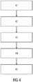
- FIG. 4 shows a flow diagram according to an embodiment of the method.
- a drive current is set to a predetermined value, for example 3A.
- a flow volume of the fluid delivery system 10 is changed.
- a corresponding, characteristic pressure behavior can be generated in the fluid delivery system 10 for the control current set in step 41.
- the speed is proportional to the delivery volume of the fluid pump 13.
- the change in the flow volume is achieved automatically, for example, by building up a pressure increase in the fluid delivery system 10. This can also take place during operation, for example when the fluid delivery system 10 is started up.
- step 43 pressure data of the fluid delivery system 10 are recorded.
- the pressure sensor 19 is used for this. This creates a volume of data that represents the pressure in the fluid delivery system for the selected control current as a function of the changed flow volume.
- step 44 it is evaluated whether all the specified values for creating the characteristic field are available. If, for example, there is a lack of data on a specific predetermined drive current for the electric motor 11, the steps 41, 42 and 43 are repeated with correspondingly changed parameters.
- a characteristic field is created from the recorded data. For this purpose, pressure values for a set control current are assigned to a speed.
- the characteristic field is leveled and aligned using anchor points and boundary parameters as described below.
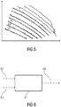
- Figure 5 shows an example of such a characteristic field.
- the individual functions increase from bottom to top and represent a control current.
- the speed is plotted on the abscissa axis, the pressure in the fluid delivery system 10 on the ordinate axis characteristic parameters are run. It is therefore necessary to level the characteristic field.
- the zero delivery rate of the fluid pump 13 is used for a fluid pump 13 for pumping gasoline. Further parameters result from a maximum speed of the electric motor 11, a maximum delivery volume of the fluid pump 13 or a minimum operating current of the electric motor 11. These parameters are in each case characteristic of different, specific fluids at different pressures. In the case of the zero delivery rate, the outlet pressure and the applied pressure at the fluid pump 13 are identical, so that the fluid is not delivered and a delivery volume is therefore zero. These Parameters and the resulting measurement data serve as anchor points for the characteristic field.
- FIG. 6 shows a schematic representation of a controlled system.
- Block 61 represents a control module that uses a characteristic field for a gasoline fluid system for control purposes.
- the block 61 has two inputs 62, 63, an input 62 is for the speed and input 63 is for the drive current.
- the output variable of block 61 is a pressure value 64.
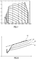
- Figure 7 shows an example of a characteristic field for a diesel fluid delivery system.
- the pressure plotted against the speed are the individual diagonal curves of increasing current from bottom to top.
- an additional calibration valve 14 is used in the fluid delivery system 10 in a further embodiment.
- the calibration valve 14 generates, as in Figure 8 shown, a kink in the pressure characteristic curves 81 to 84. This allows the characteristic curve field for the control current to be leveled, since an anchor point is created for alignment.
- Figure 10 shows a further representation for a characteristic field for diesel. Important anchor points are also not defined here.
- a special calibration valve 14 is used.
- a different number and different configurations of valves are conceivable in different configurations.
- a limited valve as shown schematically in FIG. 11, is used. Once opened, the limited valve only allows a defined amount (bypass amount) to drain. For example, the limited valve opens at 3 bar and then allows a constant flow of 5 l / h.
- a pressure-dependent inlet 112 leads to a resistor (valve flap), which is represented schematically by a spring 110. If the pressure is high enough, the outlet 111 is opened and the fluid can flow away.
- FIG 12 shows a schematic representation of a calibration valve 14 according to a further embodiment.
- the calibration valve 14 is a step valve.
- the step valve enables different bypass quantities of the fluid to flow off at different pressure levels. For example, 5 1 / h at 3 bar. and from 4 bar 10 l / h derived.
- a pressure-dependent inlet 121 leads to a resistance (valve flap), which is represented schematically by a spring 120. If the pressure is high enough, the outlet 121 is opened and the fluid can flow away. If the pressure continues to rise, the outlet 122 is additionally opened, so that the discharge quantity increases.
- valve flap resistance
- the outlet 121 is opened and the fluid can flow away.
- the outlet 122 is additionally opened, so that the discharge quantity increases.
- different numbers of stages with different values and outlet pressures are conceivable. It is important here that the recorded pressure characteristics of the fluid pump 13 have different buckling levels exhibit. The characteristic field of the control current curves can be leveled using this.
- a further embodiment of the calibration valve 14 is a step valve that only allows an outflow within a certain pressure range.
- Figure 13 shows a schematic representation of such a valve. The valve is closed at 1 bar, opened at 2 bar and closes again completely at 3 bar. Between 2.3 bar, a constant amount of 5 1 / hour. drained.
- a pressure coupling 131 leads to a resistor, which is represented schematically by a spring 130. If the pressure is high enough, the bypass volume inlet 132 is released and the fluid can flow off via the bypass volume outlet 133, which is also released. If the pressure continues to rise, the valve closes.
- Figure 14 shows different pump characteristics. Pressure characteristics of the fluid delivery system 10 are shown in bold (abscissa axis: speed; ordinate axis: pressure and control current). It can be seen here that the pressure characteristics shown in bold have different kinks. The characteristic field of the control current (thin lines) can now be leveled on the basis of these kinks. The measurement can be speed controlled. That is, the speed is reduced by the control of the electric motor 11. This can be done, for example, when the fluid pump 13 is switched on.
- Figure 15 shows similar to Figure 14 Different characteristics, but for different valve types (axis of abscissa: speed; axis of ordinate: pressure and control current).
- the additional characteristics provided by the modified valve enable flawless calibration during operation of the fluid delivery system under various realistic conditions.
- the current control can be switched on slightly below the expected operating point and the control current can be increased slightly. As soon as a speed jump occurs, it can be assumed that a calibration valve opens and the characteristic field can be aligned at this anchor point. This control current can be used to level the characteristic field. In the further work operation, speed-controlled work can be continued. Such a leveling can be used at any time, also and especially during operation. Such a bypass function has no effect on operation and does not influence the characteristic field of the control current (compare Figure 10 ). The characteristic field remains identical even when using the bypass valve or stepped valve (generally the calibration valve 14).
Landscapes
- Engineering & Computer Science (AREA)
- Mechanical Engineering (AREA)
- General Engineering & Computer Science (AREA)
- Chemical & Material Sciences (AREA)
- Combustion & Propulsion (AREA)
- Control Of Positive-Displacement Pumps (AREA)
Claims (11)
- Procédé de création d'un diagramme caractéristique d'une pompe à fluide (13) d'un système de transport de fluide (10) dépendant de la pression pour une plage de fonctionnement de la pompe à fluide (13), le système de transport de fluide (10) comprenant :- un moteur électrique (11) commandé en courant qui est commandé avec un courant d'excitation par un contrôleur de moteur (12) et qui entraîne la pompe à fluide (13) ; comprenant les étapes suivantes :- réglage du courant d'excitation à une valeur prédéterminée ;- modification d'un débit volumique du système de transport de fluide (10) après avoir réglé le courant d'excitation ;- enregistrement d'un ensemble de données décrivant la pression dans le système de transport de fluide (10) en fonction de la modification du débit volumique ;- répétition des étapes de réglage, modification et enregistrement pendant un nombre prédéterminé de répétitions et de différents courants d'excitations prédéterminés ; et- création d'un diagramme caractéristique à partir de l'ensemble de données enregistré.
- Procédé selon la revendication 1, l'étape suivante étant en plus exécutée :- détermination de zones de délimitation et/ou de points de délimitation du diagramme caractéristique en se basant sur les paramètres qui caractérisent le système de transport de fluide (10) .
- Procédé selon la revendication 1 ou 2, l'étape suivante étant en plus exécutée :- étalonnage du diagramme caractéristique en parcourant au moins une courbe caractéristique d'un courant d'excitation dans au moins une zone partielle de la courbe caractéristique.
- Procédé selon la revendication 2, le paramètre qui caractérise le système de transport de fluide (10) comprenant au moins l'un des paramètres suivants :- débit de refoulement nul de la pompe à fluide (13) ;- vitesse de rotation maximale du moteur électrique (11) ;- volume refoulé maximal de la pompe à fluide (13) ;- courant de service minimal du moteur électrique (11).
- Procédé selon l'une des revendications 1 à 4, le système de transport de fluide comportant en outre une vanne d'étalonnage (14) qui est disposée au niveau d'un côté de sortie de la pompe à fluide (13) et qui s'ouvre en fonction d'une pression prédéterminée en vue de fournir une fonction d'étalonnage dépendante de la pression et l'étape d'enregistrement étant en plus dépendante de la fonction d'étalonnage.
- Procédé selon la revendication 5, la vanne d'étalonnage (14) étant réalisée sous la forme de l'un des types de vanne suivants :- vanne à pression de seuil ;- vanne de limitation ;- vanne à étages.
- Procédé selon la revendication 6, la vanne d'étalonnage (14) étant configurée pour dériver un débit volumique maximal prédéterminé hors du système de transport de fluide (10) lorsque la vanne d'étalonnage (14) est réalisée sous la forme d'une vanne de limitation, ou étant configurée pour dériver un débit volumique maximal prédéterminé hors du système de transport de fluide (10) par étage lorsque la vanne d'étalonnage (14) est réalisée sous la forme d'une vanne à étages.
- Procédé selon l'une des revendications 1 à 7, l'étage de réglage du courant d'excitation et de modification d'un débit volumique ayant lieu à la suite d'une mise sous tension de la pompe à fluide (13), pendant que la pompe à fluide (13) est en phase de démarrage.
- Utilisation d'une vanne de limitation en tant que vanne d'étalonnage (14) dans un système de transport de fluide (10) qui est conçu pour mettre en œuvre un procédé selon l'une des revendications 1 à 4.
- Utilisation d'une vanne à étages en tant que vanne d'étalonnage (14) dans un système de transport de fluide (10) qui est conçu pour mettre en œuvre un procédé selon l'une des revendications 1 à 2.
- Contrôleur pour un système de transport de fluide (10), le système de transport de fluide (10) comprenant :- un moteur électrique (11) commandé en courant qui est régulé par un contrôleur de moteur (12) ;- une pompe à fluide (13) qui est commandée par le moteur électrique (11) ;
le contrôleur étant conçu pour mettre en œuvre un procédé selon l'une des revendications 1 à 4.
Applications Claiming Priority (2)
| Application Number | Priority Date | Filing Date | Title |
|---|---|---|---|
| DE102014222390.3A DE102014222390A1 (de) | 2014-11-03 | 2014-11-03 | Verfahren zum Erstellen eines Kennlinienfelds einer Fluidpumpe, Verwendung eines limitierten Ventils, Verwendung eines Stufenventils und Steuergerät für ein Fluidfördersystem |
| PCT/EP2015/075473 WO2016071285A1 (fr) | 2014-11-03 | 2015-11-02 | Procédé d'élaboration d'un diagramme caractéristique d'une pompe à fluide, utilisation d'une soupape limitée, utilisation d'un clapet à gradins et appareil de commande pour système de refoulement de fluide |
Publications (2)
| Publication Number | Publication Date |
|---|---|
| EP3215744A1 EP3215744A1 (fr) | 2017-09-13 |
| EP3215744B1 true EP3215744B1 (fr) | 2020-05-13 |
Family
ID=54365261
Family Applications (1)
| Application Number | Title | Priority Date | Filing Date |
|---|---|---|---|
| EP15788053.5A Active EP3215744B1 (fr) | 2014-11-03 | 2015-11-02 | Procédé d'élaboration d'un diagramme caractéristique d'une pompe à fluide, utilisation d'une soupape limitée, utilisation d'un clapet à gradins et appareil de commande pour système de refoulement de fluide |
Country Status (3)
| Country | Link |
|---|---|
| EP (1) | EP3215744B1 (fr) |
| DE (1) | DE102014222390A1 (fr) |
| WO (1) | WO2016071285A1 (fr) |
Families Citing this family (4)
| Publication number | Priority date | Publication date | Assignee | Title |
|---|---|---|---|---|
| US10859592B2 (en) * | 2017-01-31 | 2020-12-08 | Tecan Trading Ag | Method of aspirating by pipetting and pipetting apparatus |
| DE102017221333B4 (de) * | 2017-11-28 | 2021-01-28 | Vitesco Technologies GmbH | Toleranz- und Verschleißkompensation einer Kraftstoffpumpe |
| DE102017221342B4 (de) | 2017-11-28 | 2021-01-28 | Vitesco Technologies GmbH | Toleranz- und Verschleißkompensation einer Kraftstoffpumpe |
| CN112032035B (zh) * | 2020-08-13 | 2022-06-07 | 四川虹美智能科技有限公司 | 阀片损坏的确定方法及压缩机、电子设备 |
Family Cites Families (9)
| Publication number | Priority date | Publication date | Assignee | Title |
|---|---|---|---|---|
| DE3402120A1 (de) * | 1984-01-23 | 1985-07-25 | Rheinhütte vorm. Ludwig Beck GmbH & Co, 6200 Wiesbaden | Verfahren und vorrichtung zur regelung verschiedener betriebsparameter bei pumpen und verdichtern |
| DE3824057A1 (de) * | 1988-07-15 | 1990-01-25 | Loewe Pumpenfabrik Gmbh | Verfahren zur regelung des betriebes von pumpen |
| DE4243118A1 (de) * | 1992-12-21 | 1994-06-23 | Continental Ag | Verfahren zur Konstanthaltung des Druckes in einem hydraulischen System |
| DE10257657A1 (de) * | 2001-12-21 | 2003-07-03 | Ksb Ag | Hydraulische Anlage |
| WO2008067622A2 (fr) * | 2006-12-06 | 2008-06-12 | Delphi Technologies, Inc. | Procédé et appareil de commande d'écoulement de carburant dans un moteur à combustion interne |
| DE102009050083B4 (de) * | 2009-10-20 | 2016-08-18 | Viessmann Werke Gmbh & Co Kg | Verfahren zur Bestimmung eines Volumenstroms in einer mit einer Strömungsmaschine und mit einer Regelungseinheit versehenen, geschlossenen Strömungsanlage |
| DE102011015154B4 (de) * | 2011-03-25 | 2017-01-12 | Continental Automotive Gmbh | Verfahren zur Überwachung einer elektromotorisch angetriebenen Kraftstoffpumpe und Kraftstofffördereinheit mit einer Kraftstoffpumpe |
| ES2541584T3 (es) * | 2012-09-07 | 2015-07-21 | Gidelmar, S.A. | Método y equipo de control de un sistema de distribución de líquido, multipunto |
| US9528519B2 (en) * | 2012-10-12 | 2016-12-27 | Continental Automotive Systems, Inc. | Pressure control by phase current and initial adjustment at car line |
-
2014
- 2014-11-03 DE DE102014222390.3A patent/DE102014222390A1/de not_active Withdrawn
-
2015
- 2015-11-02 EP EP15788053.5A patent/EP3215744B1/fr active Active
- 2015-11-02 WO PCT/EP2015/075473 patent/WO2016071285A1/fr not_active Ceased
Non-Patent Citations (1)
| Title |
|---|
| None * |
Also Published As
| Publication number | Publication date |
|---|---|
| WO2016071285A1 (fr) | 2016-05-12 |
| DE102014222390A1 (de) | 2016-05-04 |
| EP3215744A1 (fr) | 2017-09-13 |
Similar Documents
| Publication | Publication Date | Title |
|---|---|---|
| DE102008045524B4 (de) | Verfahren zur autonomen Steuerung eines Chemikalien-Einspritzsystems für Öl- und Gas-Bohrlöcher | |
| DE60208499T2 (de) | Steuerungsverfahren für ein Common Rail Einspritzsystem bei Ausfall des Raildrucksensor | |
| EP3215744B1 (fr) | Procédé d'élaboration d'un diagramme caractéristique d'une pompe à fluide, utilisation d'une soupape limitée, utilisation d'un clapet à gradins et appareil de commande pour système de refoulement de fluide | |
| DE102007010768B4 (de) | Verfahren für die Optimierung der Ventilstellung und der Pumpendrehzahl in einem Ventilsystem mit PID-Regelung ohne die Verwendung externer Signale | |
| EP2205846B1 (fr) | Procédé de commande d'un système d'injection de carburant d'un moteur à combustion interne | |
| DE102012108027A1 (de) | Ölpumpenregelungssystem für ein Fahrzeug und Betriebsverfahren davon | |
| DE102005017837A1 (de) | Kraftstoffversorgungseinrichtung für Brennkraftmaschinen und zugehöriges Verfahren | |
| EP1568874B1 (fr) | Procédé et système de commande de débit volumétrique dans un système d'injection de carburant d' un moteur à combustion interne | |
| DE102008017160B3 (de) | Verfahren zum Bestimmen des effektiven Kompressibilitätsmoduls eines Einspritzsystems | |
| DE102014226259B4 (de) | Verfahren zum Betrieb eines Verbrennungsmotors | |
| DE19845441C2 (de) | Verfahren zum elektronischen Trimmen einer Einspritzvorrichtung | |
| DE102015212121A1 (de) | Verfahren zum Ermitteln von Betriebsparametern einer Kraftstoffpumpe | |
| DE102021209569A1 (de) | Elektronische Steuereinheit, Hydrauliksystem und Verfahren zur Steuerung eines Hydrauliksvstems | |
| DE102018205542A1 (de) | Verfahren zum Vermessen und Betreiben einer elektrischen Fluidpumpe | |
| DE102014221865B3 (de) | Verfahren zum Kalibrieren einer Fluidpumpenanordnung | |
| EP2044317B1 (fr) | Procédé de détermination d'une erreur dans une unité de dosage de carburant d'un système d'injection | |
| DE102010033317A1 (de) | Verfahren zum Bereiben eines Kraftstoffeinspritzsystems und Einspritzsystem | |
| WO2017093031A1 (fr) | Procédé de détection de la viscosité d'un carburant | |
| DE102013220831B3 (de) | Verfahren und Vorrichtung zum Betreiben eines Kraftstoffeinspritzsystems | |
| EP3234328B1 (fr) | Procédé et appareil pour diagnostiquer un systeme d'alimentation en carburant | |
| DE102015207578B3 (de) | Verfahren zur Bestimmung der Kraftstofftemperatur und/oder der Kraftstoffqualität | |
| EP3642472B1 (fr) | Dispositif et procédé de réglage de la pression de retour d'un injecteur | |
| DE102010028799A1 (de) | Verfahren zum Betreiben einer Einspritzanlage | |
| DE102017214519A1 (de) | Verfahren zur Erfassung der Viskosität des Kraftstoffs | |
| DE102015224650A1 (de) | Verfahren und System zum Ermitteln von Systemgrößen einer Axialkolbenmaschine |
Legal Events
| Date | Code | Title | Description |
|---|---|---|---|
| STAA | Information on the status of an ep patent application or granted ep patent |
Free format text: STATUS: THE INTERNATIONAL PUBLICATION HAS BEEN MADE |
|
| PUAI | Public reference made under article 153(3) epc to a published international application that has entered the european phase |
Free format text: ORIGINAL CODE: 0009012 |
|
| STAA | Information on the status of an ep patent application or granted ep patent |
Free format text: STATUS: REQUEST FOR EXAMINATION WAS MADE |
|
| 17P | Request for examination filed |
Effective date: 20170606 |
|
| AK | Designated contracting states |
Kind code of ref document: A1 Designated state(s): AL AT BE BG CH CY CZ DE DK EE ES FI FR GB GR HR HU IE IS IT LI LT LU LV MC MK MT NL NO PL PT RO RS SE SI SK SM TR |
|
| AX | Request for extension of the european patent |
Extension state: BA ME |
|
| DAV | Request for validation of the european patent (deleted) | ||
| DAX | Request for extension of the european patent (deleted) | ||
| GRAP | Despatch of communication of intention to grant a patent |
Free format text: ORIGINAL CODE: EPIDOSNIGR1 |
|
| STAA | Information on the status of an ep patent application or granted ep patent |
Free format text: STATUS: GRANT OF PATENT IS INTENDED |
|
| INTG | Intention to grant announced |
Effective date: 20191220 |
|
| GRAS | Grant fee paid |
Free format text: ORIGINAL CODE: EPIDOSNIGR3 |
|
| RAP1 | Party data changed (applicant data changed or rights of an application transferred) |
Owner name: VITESCO TECHNOLOGIES GMBH |
|
| GRAA | (expected) grant |
Free format text: ORIGINAL CODE: 0009210 |
|
| STAA | Information on the status of an ep patent application or granted ep patent |
Free format text: STATUS: THE PATENT HAS BEEN GRANTED |
|
| AK | Designated contracting states |
Kind code of ref document: B1 Designated state(s): AL AT BE BG CH CY CZ DE DK EE ES FI FR GB GR HR HU IE IS IT LI LT LU LV MC MK MT NL NO PL PT RO RS SE SI SK SM TR |
|
| REG | Reference to a national code |
Ref country code: GB Ref legal event code: FG4D Free format text: NOT ENGLISH |
|
| REG | Reference to a national code |
Ref country code: CH Ref legal event code: EP |
|
| REG | Reference to a national code |
Ref country code: DE Ref legal event code: R096 Ref document number: 502015012597 Country of ref document: DE |
|
| REG | Reference to a national code |
Ref country code: AT Ref legal event code: REF Ref document number: 1270656 Country of ref document: AT Kind code of ref document: T Effective date: 20200615 |
|
| REG | Reference to a national code |
Ref country code: LT Ref legal event code: MG4D |
|
| REG | Reference to a national code |
Ref country code: NL Ref legal event code: MP Effective date: 20200513 |
|
| PG25 | Lapsed in a contracting state [announced via postgrant information from national office to epo] |
Ref country code: SE Free format text: LAPSE BECAUSE OF FAILURE TO SUBMIT A TRANSLATION OF THE DESCRIPTION OR TO PAY THE FEE WITHIN THE PRESCRIBED TIME-LIMIT Effective date: 20200513 Ref country code: LT Free format text: LAPSE BECAUSE OF FAILURE TO SUBMIT A TRANSLATION OF THE DESCRIPTION OR TO PAY THE FEE WITHIN THE PRESCRIBED TIME-LIMIT Effective date: 20200513 Ref country code: GR Free format text: LAPSE BECAUSE OF FAILURE TO SUBMIT A TRANSLATION OF THE DESCRIPTION OR TO PAY THE FEE WITHIN THE PRESCRIBED TIME-LIMIT Effective date: 20200814 Ref country code: FI Free format text: LAPSE BECAUSE OF FAILURE TO SUBMIT A TRANSLATION OF THE DESCRIPTION OR TO PAY THE FEE WITHIN THE PRESCRIBED TIME-LIMIT Effective date: 20200513 Ref country code: NO Free format text: LAPSE BECAUSE OF FAILURE TO SUBMIT A TRANSLATION OF THE DESCRIPTION OR TO PAY THE FEE WITHIN THE PRESCRIBED TIME-LIMIT Effective date: 20200813 Ref country code: IS Free format text: LAPSE BECAUSE OF FAILURE TO SUBMIT A TRANSLATION OF THE DESCRIPTION OR TO PAY THE FEE WITHIN THE PRESCRIBED TIME-LIMIT Effective date: 20200913 Ref country code: PT Free format text: LAPSE BECAUSE OF FAILURE TO SUBMIT A TRANSLATION OF THE DESCRIPTION OR TO PAY THE FEE WITHIN THE PRESCRIBED TIME-LIMIT Effective date: 20200914 |
|
| PG25 | Lapsed in a contracting state [announced via postgrant information from national office to epo] |
Ref country code: LV Free format text: LAPSE BECAUSE OF FAILURE TO SUBMIT A TRANSLATION OF THE DESCRIPTION OR TO PAY THE FEE WITHIN THE PRESCRIBED TIME-LIMIT Effective date: 20200513 Ref country code: HR Free format text: LAPSE BECAUSE OF FAILURE TO SUBMIT A TRANSLATION OF THE DESCRIPTION OR TO PAY THE FEE WITHIN THE PRESCRIBED TIME-LIMIT Effective date: 20200513 Ref country code: RS Free format text: LAPSE BECAUSE OF FAILURE TO SUBMIT A TRANSLATION OF THE DESCRIPTION OR TO PAY THE FEE WITHIN THE PRESCRIBED TIME-LIMIT Effective date: 20200513 Ref country code: BG Free format text: LAPSE BECAUSE OF FAILURE TO SUBMIT A TRANSLATION OF THE DESCRIPTION OR TO PAY THE FEE WITHIN THE PRESCRIBED TIME-LIMIT Effective date: 20200813 |
|
| PG25 | Lapsed in a contracting state [announced via postgrant information from national office to epo] |
Ref country code: NL Free format text: LAPSE BECAUSE OF FAILURE TO SUBMIT A TRANSLATION OF THE DESCRIPTION OR TO PAY THE FEE WITHIN THE PRESCRIBED TIME-LIMIT Effective date: 20200513 Ref country code: AL Free format text: LAPSE BECAUSE OF FAILURE TO SUBMIT A TRANSLATION OF THE DESCRIPTION OR TO PAY THE FEE WITHIN THE PRESCRIBED TIME-LIMIT Effective date: 20200513 |
|
| PG25 | Lapsed in a contracting state [announced via postgrant information from national office to epo] |
Ref country code: RO Free format text: LAPSE BECAUSE OF FAILURE TO SUBMIT A TRANSLATION OF THE DESCRIPTION OR TO PAY THE FEE WITHIN THE PRESCRIBED TIME-LIMIT Effective date: 20200513 Ref country code: CZ Free format text: LAPSE BECAUSE OF FAILURE TO SUBMIT A TRANSLATION OF THE DESCRIPTION OR TO PAY THE FEE WITHIN THE PRESCRIBED TIME-LIMIT Effective date: 20200513 Ref country code: ES Free format text: LAPSE BECAUSE OF FAILURE TO SUBMIT A TRANSLATION OF THE DESCRIPTION OR TO PAY THE FEE WITHIN THE PRESCRIBED TIME-LIMIT Effective date: 20200513 Ref country code: EE Free format text: LAPSE BECAUSE OF FAILURE TO SUBMIT A TRANSLATION OF THE DESCRIPTION OR TO PAY THE FEE WITHIN THE PRESCRIBED TIME-LIMIT Effective date: 20200513 Ref country code: DK Free format text: LAPSE BECAUSE OF FAILURE TO SUBMIT A TRANSLATION OF THE DESCRIPTION OR TO PAY THE FEE WITHIN THE PRESCRIBED TIME-LIMIT Effective date: 20200513 Ref country code: IT Free format text: LAPSE BECAUSE OF FAILURE TO SUBMIT A TRANSLATION OF THE DESCRIPTION OR TO PAY THE FEE WITHIN THE PRESCRIBED TIME-LIMIT Effective date: 20200513 Ref country code: SM Free format text: LAPSE BECAUSE OF FAILURE TO SUBMIT A TRANSLATION OF THE DESCRIPTION OR TO PAY THE FEE WITHIN THE PRESCRIBED TIME-LIMIT Effective date: 20200513 |
|
| REG | Reference to a national code |
Ref country code: DE Ref legal event code: R097 Ref document number: 502015012597 Country of ref document: DE |
|
| PG25 | Lapsed in a contracting state [announced via postgrant information from national office to epo] |
Ref country code: PL Free format text: LAPSE BECAUSE OF FAILURE TO SUBMIT A TRANSLATION OF THE DESCRIPTION OR TO PAY THE FEE WITHIN THE PRESCRIBED TIME-LIMIT Effective date: 20200513 Ref country code: SK Free format text: LAPSE BECAUSE OF FAILURE TO SUBMIT A TRANSLATION OF THE DESCRIPTION OR TO PAY THE FEE WITHIN THE PRESCRIBED TIME-LIMIT Effective date: 20200513 |
|
| PLBE | No opposition filed within time limit |
Free format text: ORIGINAL CODE: 0009261 |
|
| STAA | Information on the status of an ep patent application or granted ep patent |
Free format text: STATUS: NO OPPOSITION FILED WITHIN TIME LIMIT |
|
| 26N | No opposition filed |
Effective date: 20210216 |
|
| PG25 | Lapsed in a contracting state [announced via postgrant information from national office to epo] |
Ref country code: SI Free format text: LAPSE BECAUSE OF FAILURE TO SUBMIT A TRANSLATION OF THE DESCRIPTION OR TO PAY THE FEE WITHIN THE PRESCRIBED TIME-LIMIT Effective date: 20200513 |
|
| PG25 | Lapsed in a contracting state [announced via postgrant information from national office to epo] |
Ref country code: MC Free format text: LAPSE BECAUSE OF FAILURE TO SUBMIT A TRANSLATION OF THE DESCRIPTION OR TO PAY THE FEE WITHIN THE PRESCRIBED TIME-LIMIT Effective date: 20200513 |
|
| REG | Reference to a national code |
Ref country code: CH Ref legal event code: PL |
|
| GBPC | Gb: european patent ceased through non-payment of renewal fee |
Effective date: 20201102 |
|
| PG25 | Lapsed in a contracting state [announced via postgrant information from national office to epo] |
Ref country code: LU Free format text: LAPSE BECAUSE OF NON-PAYMENT OF DUE FEES Effective date: 20201102 |
|
| REG | Reference to a national code |
Ref country code: BE Ref legal event code: MM Effective date: 20201130 |
|
| PG25 | Lapsed in a contracting state [announced via postgrant information from national office to epo] |
Ref country code: LI Free format text: LAPSE BECAUSE OF NON-PAYMENT OF DUE FEES Effective date: 20201130 Ref country code: CH Free format text: LAPSE BECAUSE OF NON-PAYMENT OF DUE FEES Effective date: 20201130 |
|
| PG25 | Lapsed in a contracting state [announced via postgrant information from national office to epo] |
Ref country code: IE Free format text: LAPSE BECAUSE OF NON-PAYMENT OF DUE FEES Effective date: 20201102 |
|
| PG25 | Lapsed in a contracting state [announced via postgrant information from national office to epo] |
Ref country code: GB Free format text: LAPSE BECAUSE OF NON-PAYMENT OF DUE FEES Effective date: 20201102 |
|
| REG | Reference to a national code |
Ref country code: DE Ref legal event code: R081 Ref document number: 502015012597 Country of ref document: DE Owner name: SCHAEFFLER TECHNOLOGIES AG & CO. KG, DE Free format text: FORMER OWNER: VITESCO TECHNOLOGIES GMBH, 30165 HANNOVER, DE Ref country code: DE Ref legal event code: R081 Ref document number: 502015012597 Country of ref document: DE Owner name: VITESCO TECHNOLOGIES GMBH, DE Free format text: FORMER OWNER: VITESCO TECHNOLOGIES GMBH, 30165 HANNOVER, DE |
|
| REG | Reference to a national code |
Ref country code: AT Ref legal event code: MM01 Ref document number: 1270656 Country of ref document: AT Kind code of ref document: T Effective date: 20201102 |
|
| PG25 | Lapsed in a contracting state [announced via postgrant information from national office to epo] |
Ref country code: AT Free format text: LAPSE BECAUSE OF NON-PAYMENT OF DUE FEES Effective date: 20201102 |
|
| PG25 | Lapsed in a contracting state [announced via postgrant information from national office to epo] |
Ref country code: TR Free format text: LAPSE BECAUSE OF FAILURE TO SUBMIT A TRANSLATION OF THE DESCRIPTION OR TO PAY THE FEE WITHIN THE PRESCRIBED TIME-LIMIT Effective date: 20200513 Ref country code: MT Free format text: LAPSE BECAUSE OF FAILURE TO SUBMIT A TRANSLATION OF THE DESCRIPTION OR TO PAY THE FEE WITHIN THE PRESCRIBED TIME-LIMIT Effective date: 20200513 Ref country code: CY Free format text: LAPSE BECAUSE OF FAILURE TO SUBMIT A TRANSLATION OF THE DESCRIPTION OR TO PAY THE FEE WITHIN THE PRESCRIBED TIME-LIMIT Effective date: 20200513 |
|
| PG25 | Lapsed in a contracting state [announced via postgrant information from national office to epo] |
Ref country code: MK Free format text: LAPSE BECAUSE OF FAILURE TO SUBMIT A TRANSLATION OF THE DESCRIPTION OR TO PAY THE FEE WITHIN THE PRESCRIBED TIME-LIMIT Effective date: 20200513 |
|
| PG25 | Lapsed in a contracting state [announced via postgrant information from national office to epo] |
Ref country code: BE Free format text: LAPSE BECAUSE OF NON-PAYMENT OF DUE FEES Effective date: 20201130 |
|
| P01 | Opt-out of the competence of the unified patent court (upc) registered |
Effective date: 20230530 |
|
| REG | Reference to a national code |
Ref country code: DE Ref legal event code: R081 Ref document number: 502015012597 Country of ref document: DE Owner name: SCHAEFFLER TECHNOLOGIES AG & CO. KG, DE Free format text: FORMER OWNER: VITESCO TECHNOLOGIES GMBH, 93055 REGENSBURG, DE |
|
| PG25 | Lapsed in a contracting state [announced via postgrant information from national office to epo] |
Ref country code: IS Free format text: LAPSE BECAUSE OF NON-PAYMENT OF DUE FEES Effective date: 20200913 |
|
| PGFP | Annual fee paid to national office [announced via postgrant information from national office to epo] |
Ref country code: DE Payment date: 20251130 Year of fee payment: 11 |
|
| PGFP | Annual fee paid to national office [announced via postgrant information from national office to epo] |
Ref country code: FR Payment date: 20251126 Year of fee payment: 11 |