EP3215259B1 - Dispositif pour la dissolution d'un gaz dans un liquide - Google Patents
Dispositif pour la dissolution d'un gaz dans un liquide Download PDFInfo
- Publication number
- EP3215259B1 EP3215259B1 EP15794243.4A EP15794243A EP3215259B1 EP 3215259 B1 EP3215259 B1 EP 3215259B1 EP 15794243 A EP15794243 A EP 15794243A EP 3215259 B1 EP3215259 B1 EP 3215259B1
- Authority
- EP
- European Patent Office
- Prior art keywords
- liquid
- oxygen
- gas
- inlet
- pump
- Prior art date
- Legal status (The legal status is an assumption and is not a legal conclusion. Google has not performed a legal analysis and makes no representation as to the accuracy of the status listed.)
- Active
Links
- 239000007788 liquid Substances 0.000 title claims description 581
- QVGXLLKOCUKJST-UHFFFAOYSA-N atomic oxygen Chemical compound [O] QVGXLLKOCUKJST-UHFFFAOYSA-N 0.000 claims description 254
- 239000001301 oxygen Substances 0.000 claims description 254
- 229910052760 oxygen Inorganic materials 0.000 claims description 254
- 239000007789 gas Substances 0.000 claims description 180
- 239000000463 material Substances 0.000 claims description 101
- 239000012530 fluid Substances 0.000 claims description 66
- 238000004891 communication Methods 0.000 claims description 53
- 210000004027 cell Anatomy 0.000 claims description 35
- 238000009792 diffusion process Methods 0.000 claims description 30
- 229910001220 stainless steel Inorganic materials 0.000 claims description 30
- 239000010935 stainless steel Substances 0.000 claims description 30
- 238000005259 measurement Methods 0.000 claims description 29
- 238000011144 upstream manufacturing Methods 0.000 claims description 20
- 229920000642 polymer Polymers 0.000 claims description 12
- 238000009530 blood pressure measurement Methods 0.000 claims description 7
- 238000009529 body temperature measurement Methods 0.000 claims description 7
- -1 cell media Substances 0.000 claims description 4
- 239000006285 cell suspension Substances 0.000 claims description 4
- 241000588724 Escherichia coli Species 0.000 claims description 3
- 210000004369 blood Anatomy 0.000 claims description 3
- 239000008280 blood Substances 0.000 claims description 3
- XLYOFNOQVPJJNP-UHFFFAOYSA-N water Substances O XLYOFNOQVPJJNP-UHFFFAOYSA-N 0.000 claims description 3
- 241000233866 Fungi Species 0.000 claims description 2
- 241000238631 Hexapoda Species 0.000 claims description 2
- 241001148470 aerobic bacillus Species 0.000 claims description 2
- 210000004102 animal cell Anatomy 0.000 claims description 2
- 230000002421 anti-septic effect Effects 0.000 claims description 2
- 239000000872 buffer Substances 0.000 claims description 2
- 239000000882 contact lens solution Substances 0.000 claims description 2
- LOKCTEFSRHRXRJ-UHFFFAOYSA-I dipotassium trisodium dihydrogen phosphate hydrogen phosphate dichloride Chemical compound P(=O)(O)(O)[O-].[K+].P(=O)(O)([O-])[O-].[Na+].[Na+].[Cl-].[K+].[Cl-].[Na+] LOKCTEFSRHRXRJ-UHFFFAOYSA-I 0.000 claims description 2
- 239000008267 milk Substances 0.000 claims description 2
- 210000004080 milk Anatomy 0.000 claims description 2
- 235000013336 milk Nutrition 0.000 claims description 2
- 239000002953 phosphate buffered saline Substances 0.000 claims description 2
- 239000000243 solution Substances 0.000 claims description 2
- 241001148471 unidentified anaerobic bacterium Species 0.000 claims description 2
- 238000006213 oxygenation reaction Methods 0.000 description 100
- 239000006260 foam Substances 0.000 description 60
- IJGRMHOSHXDMSA-UHFFFAOYSA-N Atomic nitrogen Chemical compound N#N IJGRMHOSHXDMSA-UHFFFAOYSA-N 0.000 description 29
- 238000004519 manufacturing process Methods 0.000 description 19
- 238000002156 mixing Methods 0.000 description 18
- 229920001983 poloxamer Polymers 0.000 description 17
- CURLTUGMZLYLDI-UHFFFAOYSA-N Carbon dioxide Chemical compound O=C=O CURLTUGMZLYLDI-UHFFFAOYSA-N 0.000 description 16
- RVGRUAULSDPKGF-UHFFFAOYSA-N Poloxamer Chemical compound C1CO1.CC1CO1 RVGRUAULSDPKGF-UHFFFAOYSA-N 0.000 description 16
- 229960000502 poloxamer Drugs 0.000 description 16
- 239000000203 mixture Substances 0.000 description 14
- 229910052757 nitrogen Inorganic materials 0.000 description 14
- 239000006144 Dulbecco’s modified Eagle's medium Substances 0.000 description 13
- 238000004064 recycling Methods 0.000 description 13
- 239000006143 cell culture medium Substances 0.000 description 10
- 230000001706 oxygenating effect Effects 0.000 description 9
- 239000001569 carbon dioxide Substances 0.000 description 8
- 229910002092 carbon dioxide Inorganic materials 0.000 description 8
- 238000000034 method Methods 0.000 description 8
- 239000000654 additive Substances 0.000 description 7
- 239000003792 electrolyte Substances 0.000 description 6
- 238000001990 intravenous administration Methods 0.000 description 6
- 238000011960 computer-aided design Methods 0.000 description 5
- 238000002604 ultrasonography Methods 0.000 description 5
- 238000010586 diagram Methods 0.000 description 4
- 229910003460 diamond Inorganic materials 0.000 description 4
- 239000010432 diamond Substances 0.000 description 4
- 229910052500 inorganic mineral Inorganic materials 0.000 description 4
- 238000003801 milling Methods 0.000 description 4
- 239000011707 mineral Substances 0.000 description 4
- 238000013022 venting Methods 0.000 description 4
- 230000000996 additive effect Effects 0.000 description 3
- 230000008901 benefit Effects 0.000 description 3
- 239000011521 glass Substances 0.000 description 3
- 230000005484 gravity Effects 0.000 description 3
- 238000010438 heat treatment Methods 0.000 description 3
- 239000002609 medium Substances 0.000 description 3
- 150000003839 salts Chemical class 0.000 description 3
- 238000003756 stirring Methods 0.000 description 3
- XKRFYHLGVUSROY-UHFFFAOYSA-N Argon Chemical compound [Ar] XKRFYHLGVUSROY-UHFFFAOYSA-N 0.000 description 2
- 108091003079 Bovine Serum Albumin Proteins 0.000 description 2
- WQZGKKKJIJFFOK-GASJEMHNSA-N Glucose Natural products OC[C@H]1OC(O)[C@H](O)[C@@H](O)[C@@H]1O WQZGKKKJIJFFOK-GASJEMHNSA-N 0.000 description 2
- XEEYBQQBJWHFJM-UHFFFAOYSA-N Iron Chemical compound [Fe] XEEYBQQBJWHFJM-UHFFFAOYSA-N 0.000 description 2
- AUNGANRZJHBGPY-SCRDCRAPSA-N Riboflavin Chemical compound OC[C@@H](O)[C@@H](O)[C@@H](O)CN1C=2C=C(C)C(C)=CC=2N=C2C1=NC(=O)NC2=O AUNGANRZJHBGPY-SCRDCRAPSA-N 0.000 description 2
- 238000010521 absorption reaction Methods 0.000 description 2
- 239000012080 ambient air Substances 0.000 description 2
- 238000004113 cell culture Methods 0.000 description 2
- 238000011109 contamination Methods 0.000 description 2
- 238000012258 culturing Methods 0.000 description 2
- 150000002016 disaccharides Chemical class 0.000 description 2
- 238000006073 displacement reaction Methods 0.000 description 2
- 239000012091 fetal bovine serum Substances 0.000 description 2
- 230000009969 flowable effect Effects 0.000 description 2
- OVBPIULPVIDEAO-LBPRGKRZSA-N folic acid Chemical compound C=1N=C2NC(N)=NC(=O)C2=NC=1CNC1=CC=C(C(=O)N[C@@H](CCC(O)=O)C(O)=O)C=C1 OVBPIULPVIDEAO-LBPRGKRZSA-N 0.000 description 2
- 239000000499 gel Substances 0.000 description 2
- 239000008103 glucose Substances 0.000 description 2
- 150000002772 monosaccharides Chemical class 0.000 description 2
- 238000000465 moulding Methods 0.000 description 2
- 150000007523 nucleic acids Chemical class 0.000 description 2
- 235000015097 nutrients Nutrition 0.000 description 2
- 230000002572 peristaltic effect Effects 0.000 description 2
- 229920001343 polytetrafluoroethylene Polymers 0.000 description 2
- 239000004810 polytetrafluoroethylene Substances 0.000 description 2
- 108090000623 proteins and genes Chemical group 0.000 description 2
- 102000004169 proteins and genes Human genes 0.000 description 2
- 238000003908 quality control method Methods 0.000 description 2
- 239000000523 sample Substances 0.000 description 2
- 238000012546 transfer Methods 0.000 description 2
- 241000894006 Bacteria Species 0.000 description 1
- ZOXJGFHDIHLPTG-UHFFFAOYSA-N Boron Chemical compound [B] ZOXJGFHDIHLPTG-UHFFFAOYSA-N 0.000 description 1
- OYPRJOBELJOOCE-UHFFFAOYSA-N Calcium Chemical compound [Ca] OYPRJOBELJOOCE-UHFFFAOYSA-N 0.000 description 1
- OKTJSMMVPCPJKN-UHFFFAOYSA-N Carbon Chemical compound [C] OKTJSMMVPCPJKN-UHFFFAOYSA-N 0.000 description 1
- ZAMOUSCENKQFHK-UHFFFAOYSA-N Chlorine atom Chemical compound [Cl] ZAMOUSCENKQFHK-UHFFFAOYSA-N 0.000 description 1
- 239000004155 Chlorine dioxide Substances 0.000 description 1
- AUNGANRZJHBGPY-UHFFFAOYSA-N D-Lyxoflavin Natural products OCC(O)C(O)C(O)CN1C=2C=C(C)C(C)=CC=2N=C2C1=NC(=O)NC2=O AUNGANRZJHBGPY-UHFFFAOYSA-N 0.000 description 1
- 239000006145 Eagle's minimal essential medium Substances 0.000 description 1
- DGAQECJNVWCQMB-PUAWFVPOSA-M Ilexoside XXIX Chemical compound C[C@@H]1CC[C@@]2(CC[C@@]3(C(=CC[C@H]4[C@]3(CC[C@@H]5[C@@]4(CC[C@@H](C5(C)C)OS(=O)(=O)[O-])C)C)[C@@H]2[C@]1(C)O)C)C(=O)O[C@H]6[C@@H]([C@H]([C@@H]([C@H](O6)CO)O)O)O.[Na+] DGAQECJNVWCQMB-PUAWFVPOSA-M 0.000 description 1
- QIVBCDIJIAJPQS-VIFPVBQESA-N L-tryptophane Chemical compound C1=CC=C2C(C[C@H](N)C(O)=O)=CNC2=C1 QIVBCDIJIAJPQS-VIFPVBQESA-N 0.000 description 1
- FYYHWMGAXLPEAU-UHFFFAOYSA-N Magnesium Chemical compound [Mg] FYYHWMGAXLPEAU-UHFFFAOYSA-N 0.000 description 1
- PWHULOQIROXLJO-UHFFFAOYSA-N Manganese Chemical compound [Mn] PWHULOQIROXLJO-UHFFFAOYSA-N 0.000 description 1
- ZOKXTWBITQBERF-UHFFFAOYSA-N Molybdenum Chemical compound [Mo] ZOKXTWBITQBERF-UHFFFAOYSA-N 0.000 description 1
- OVBPIULPVIDEAO-UHFFFAOYSA-N N-Pteroyl-L-glutaminsaeure Natural products C=1N=C2NC(N)=NC(=O)C2=NC=1CNC1=CC=C(C(=O)NC(CCC(O)=O)C(O)=O)C=C1 OVBPIULPVIDEAO-UHFFFAOYSA-N 0.000 description 1
- 229910002651 NO3 Inorganic materials 0.000 description 1
- NHNBFGGVMKEFGY-UHFFFAOYSA-N Nitrate Chemical class [O-][N+]([O-])=O NHNBFGGVMKEFGY-UHFFFAOYSA-N 0.000 description 1
- 239000004677 Nylon Substances 0.000 description 1
- 102000015636 Oligopeptides Human genes 0.000 description 1
- 108010038807 Oligopeptides Proteins 0.000 description 1
- ZLMJMSJWJFRBEC-UHFFFAOYSA-N Potassium Chemical compound [K] ZLMJMSJWJFRBEC-UHFFFAOYSA-N 0.000 description 1
- 240000004808 Saccharomyces cerevisiae Species 0.000 description 1
- QIVBCDIJIAJPQS-UHFFFAOYSA-N Tryptophan Natural products C1=CC=C2C(CC(N)C(O)=O)=CNC2=C1 QIVBCDIJIAJPQS-UHFFFAOYSA-N 0.000 description 1
- HCHKCACWOHOZIP-UHFFFAOYSA-N Zinc Chemical compound [Zn] HCHKCACWOHOZIP-UHFFFAOYSA-N 0.000 description 1
- DFPAKSUCGFBDDF-ZQBYOMGUSA-N [14c]-nicotinamide Chemical compound N[14C](=O)C1=CC=CN=C1 DFPAKSUCGFBDDF-ZQBYOMGUSA-N 0.000 description 1
- 230000003213 activating effect Effects 0.000 description 1
- 238000004026 adhesive bonding Methods 0.000 description 1
- 238000010564 aerobic fermentation Methods 0.000 description 1
- 239000003570 air Substances 0.000 description 1
- 150000001413 amino acids Chemical class 0.000 description 1
- 150000003868 ammonium compounds Chemical class 0.000 description 1
- 229910052786 argon Inorganic materials 0.000 description 1
- 230000004888 barrier function Effects 0.000 description 1
- 230000009286 beneficial effect Effects 0.000 description 1
- 229910052796 boron Inorganic materials 0.000 description 1
- 239000011575 calcium Substances 0.000 description 1
- 229910052791 calcium Inorganic materials 0.000 description 1
- 150000001720 carbohydrates Chemical class 0.000 description 1
- 229910052799 carbon Inorganic materials 0.000 description 1
- OSVXSBDYLRYLIG-UHFFFAOYSA-N chlorine dioxide Inorganic materials O=Cl=O OSVXSBDYLRYLIG-UHFFFAOYSA-N 0.000 description 1
- 239000010941 cobalt Substances 0.000 description 1
- 229910017052 cobalt Inorganic materials 0.000 description 1
- GUTLYIVDDKVIGB-UHFFFAOYSA-N cobalt atom Chemical compound [Co] GUTLYIVDDKVIGB-UHFFFAOYSA-N 0.000 description 1
- 238000005260 corrosion Methods 0.000 description 1
- 230000007797 corrosion Effects 0.000 description 1
- 230000006378 damage Effects 0.000 description 1
- 230000003247 decreasing effect Effects 0.000 description 1
- 230000002939 deleterious effect Effects 0.000 description 1
- 230000001419 dependent effect Effects 0.000 description 1
- 230000001627 detrimental effect Effects 0.000 description 1
- 230000000694 effects Effects 0.000 description 1
- 239000003797 essential amino acid Substances 0.000 description 1
- 235000020776 essential amino acid Nutrition 0.000 description 1
- 238000000855 fermentation Methods 0.000 description 1
- 229920005570 flexible polymer Polymers 0.000 description 1
- 229960000304 folic acid Drugs 0.000 description 1
- 235000019152 folic acid Nutrition 0.000 description 1
- 239000011724 folic acid Substances 0.000 description 1
- 239000012634 fragment Substances 0.000 description 1
- ZDXPYRJPNDTMRX-UHFFFAOYSA-N glutamine Natural products OC(=O)C(N)CCC(N)=O ZDXPYRJPNDTMRX-UHFFFAOYSA-N 0.000 description 1
- 150000004676 glycans Chemical class 0.000 description 1
- 238000004128 high performance liquid chromatography Methods 0.000 description 1
- 239000003501 hydroponics Substances 0.000 description 1
- 208000015181 infectious disease Diseases 0.000 description 1
- 229910052742 iron Inorganic materials 0.000 description 1
- 239000000644 isotonic solution Substances 0.000 description 1
- 150000002632 lipids Chemical class 0.000 description 1
- 239000011777 magnesium Substances 0.000 description 1
- 229910052749 magnesium Inorganic materials 0.000 description 1
- 210000004962 mammalian cell Anatomy 0.000 description 1
- 229910052748 manganese Inorganic materials 0.000 description 1
- 239000011572 manganese Substances 0.000 description 1
- 229910052751 metal Inorganic materials 0.000 description 1
- 239000002184 metal Substances 0.000 description 1
- 229910052750 molybdenum Inorganic materials 0.000 description 1
- 239000011733 molybdenum Substances 0.000 description 1
- 150000002816 nickel compounds Chemical class 0.000 description 1
- 150000002823 nitrates Chemical group 0.000 description 1
- 102000039446 nucleic acids Human genes 0.000 description 1
- 108020004707 nucleic acids Proteins 0.000 description 1
- 229920001778 nylon Polymers 0.000 description 1
- 229920001542 oligosaccharide Polymers 0.000 description 1
- 150000002482 oligosaccharides Polymers 0.000 description 1
- 239000004033 plastic Substances 0.000 description 1
- 229920001282 polysaccharide Polymers 0.000 description 1
- 239000005017 polysaccharide Substances 0.000 description 1
- 239000011591 potassium Substances 0.000 description 1
- 229910052700 potassium Inorganic materials 0.000 description 1
- 238000002360 preparation method Methods 0.000 description 1
- 238000005086 pumping Methods 0.000 description 1
- 229960002477 riboflavin Drugs 0.000 description 1
- 235000019192 riboflavin Nutrition 0.000 description 1
- 239000002151 riboflavin Substances 0.000 description 1
- 239000011734 sodium Substances 0.000 description 1
- 229910052708 sodium Inorganic materials 0.000 description 1
- 210000000130 stem cell Anatomy 0.000 description 1
- 238000004659 sterilization and disinfection Methods 0.000 description 1
- 239000000126 substance Substances 0.000 description 1
- 230000004083 survival effect Effects 0.000 description 1
- 230000001225 therapeutic effect Effects 0.000 description 1
- 229920001169 thermoplastic Polymers 0.000 description 1
- 229920000428 triblock copolymer Polymers 0.000 description 1
- 235000013343 vitamin Nutrition 0.000 description 1
- 239000011782 vitamin Substances 0.000 description 1
- 229940088594 vitamin Drugs 0.000 description 1
- 229930003231 vitamin Natural products 0.000 description 1
- 239000002699 waste material Substances 0.000 description 1
- 238000003466 welding Methods 0.000 description 1
- 229910052725 zinc Inorganic materials 0.000 description 1
- 239000011701 zinc Substances 0.000 description 1
Images


Classifications
-
- B—PERFORMING OPERATIONS; TRANSPORTING
- B01—PHYSICAL OR CHEMICAL PROCESSES OR APPARATUS IN GENERAL
- B01F—MIXING, e.g. DISSOLVING, EMULSIFYING OR DISPERSING
- B01F25/00—Flow mixers; Mixers for falling materials, e.g. solid particles
- B01F25/40—Static mixers
- B01F25/42—Static mixers in which the mixing is affected by moving the components jointly in changing directions, e.g. in tubes provided with baffles or obstructions
- B01F25/43—Mixing tubes, e.g. wherein the material is moved in a radial or partly reversed direction
- B01F25/433—Mixing tubes wherein the shape of the tube influences the mixing, e.g. mixing tubes with varying cross-section or provided with inwardly extending profiles
- B01F25/4335—Mixers with a converging-diverging cross-section
-
- B—PERFORMING OPERATIONS; TRANSPORTING
- B01—PHYSICAL OR CHEMICAL PROCESSES OR APPARATUS IN GENERAL
- B01F—MIXING, e.g. DISSOLVING, EMULSIFYING OR DISPERSING
- B01F23/00—Mixing according to the phases to be mixed, e.g. dispersing or emulsifying
- B01F23/20—Mixing gases with liquids
- B01F23/23—Mixing gases with liquids by introducing gases into liquid media, e.g. for producing aerated liquids
- B01F23/232—Mixing gases with liquids by introducing gases into liquid media, e.g. for producing aerated liquids using flow-mixing means for introducing the gases, e.g. baffles
- B01F23/2323—Mixing gases with liquids by introducing gases into liquid media, e.g. for producing aerated liquids using flow-mixing means for introducing the gases, e.g. baffles by circulating the flow in guiding constructions or conduits
-
- B—PERFORMING OPERATIONS; TRANSPORTING
- B01—PHYSICAL OR CHEMICAL PROCESSES OR APPARATUS IN GENERAL
- B01F—MIXING, e.g. DISSOLVING, EMULSIFYING OR DISPERSING
- B01F23/00—Mixing according to the phases to be mixed, e.g. dispersing or emulsifying
- B01F23/20—Mixing gases with liquids
- B01F23/29—Mixing systems, i.e. flow charts or diagrams
-
- B—PERFORMING OPERATIONS; TRANSPORTING
- B01—PHYSICAL OR CHEMICAL PROCESSES OR APPARATUS IN GENERAL
- B01F—MIXING, e.g. DISSOLVING, EMULSIFYING OR DISPERSING
- B01F25/00—Flow mixers; Mixers for falling materials, e.g. solid particles
- B01F25/40—Static mixers
- B01F25/42—Static mixers in which the mixing is affected by moving the components jointly in changing directions, e.g. in tubes provided with baffles or obstructions
- B01F25/43—Mixing tubes, e.g. wherein the material is moved in a radial or partly reversed direction
- B01F25/433—Mixing tubes wherein the shape of the tube influences the mixing, e.g. mixing tubes with varying cross-section or provided with inwardly extending profiles
- B01F25/4338—Mixers with a succession of converging-diverging cross-sections, i.e. undulating cross-section
-
- B—PERFORMING OPERATIONS; TRANSPORTING
- B01—PHYSICAL OR CHEMICAL PROCESSES OR APPARATUS IN GENERAL
- B01F—MIXING, e.g. DISSOLVING, EMULSIFYING OR DISPERSING
- B01F25/00—Flow mixers; Mixers for falling materials, e.g. solid particles
- B01F25/50—Circulation mixers, e.g. wherein at least part of the mixture is discharged from and reintroduced into a receptacle
- B01F25/53—Circulation mixers, e.g. wherein at least part of the mixture is discharged from and reintroduced into a receptacle in which the mixture is discharged from and reintroduced into a receptacle through a recirculation tube, into which an additional component is introduced
-
- B—PERFORMING OPERATIONS; TRANSPORTING
- B01—PHYSICAL OR CHEMICAL PROCESSES OR APPARATUS IN GENERAL
- B01F—MIXING, e.g. DISSOLVING, EMULSIFYING OR DISPERSING
- B01F33/00—Other mixers; Mixing plants; Combinations of mixers
- B01F33/30—Micromixers
-
- B—PERFORMING OPERATIONS; TRANSPORTING
- B01—PHYSICAL OR CHEMICAL PROCESSES OR APPARATUS IN GENERAL
- B01F—MIXING, e.g. DISSOLVING, EMULSIFYING OR DISPERSING
- B01F33/00—Other mixers; Mixing plants; Combinations of mixers
- B01F33/80—Mixing plants; Combinations of mixers
- B01F33/81—Combinations of similar mixers, e.g. with rotary stirring devices in two or more receptacles
- B01F33/813—Combinations of similar mixers, e.g. with rotary stirring devices in two or more receptacles mixing simultaneously in two or more mixing receptacles
-
- B—PERFORMING OPERATIONS; TRANSPORTING
- B01—PHYSICAL OR CHEMICAL PROCESSES OR APPARATUS IN GENERAL
- B01F—MIXING, e.g. DISSOLVING, EMULSIFYING OR DISPERSING
- B01F35/00—Accessories for mixers; Auxiliary operations or auxiliary devices; Parts or details of general application
- B01F35/20—Measuring; Control or regulation
- B01F35/21—Measuring
- B01F35/211—Measuring of the operational parameters
- B01F35/2111—Flow rate
-
- B—PERFORMING OPERATIONS; TRANSPORTING
- B01—PHYSICAL OR CHEMICAL PROCESSES OR APPARATUS IN GENERAL
- B01F—MIXING, e.g. DISSOLVING, EMULSIFYING OR DISPERSING
- B01F35/00—Accessories for mixers; Auxiliary operations or auxiliary devices; Parts or details of general application
- B01F35/20—Measuring; Control or regulation
- B01F35/21—Measuring
- B01F35/211—Measuring of the operational parameters
- B01F35/2112—Level of material in a container or the position or shape of the upper surface of the material
-
- B—PERFORMING OPERATIONS; TRANSPORTING
- B01—PHYSICAL OR CHEMICAL PROCESSES OR APPARATUS IN GENERAL
- B01F—MIXING, e.g. DISSOLVING, EMULSIFYING OR DISPERSING
- B01F35/00—Accessories for mixers; Auxiliary operations or auxiliary devices; Parts or details of general application
- B01F35/20—Measuring; Control or regulation
- B01F35/21—Measuring
- B01F35/211—Measuring of the operational parameters
- B01F35/2113—Pressure
-
- B—PERFORMING OPERATIONS; TRANSPORTING
- B01—PHYSICAL OR CHEMICAL PROCESSES OR APPARATUS IN GENERAL
- B01F—MIXING, e.g. DISSOLVING, EMULSIFYING OR DISPERSING
- B01F35/00—Accessories for mixers; Auxiliary operations or auxiliary devices; Parts or details of general application
- B01F35/20—Measuring; Control or regulation
- B01F35/21—Measuring
- B01F35/211—Measuring of the operational parameters
- B01F35/2115—Temperature
-
- B—PERFORMING OPERATIONS; TRANSPORTING
- B01—PHYSICAL OR CHEMICAL PROCESSES OR APPARATUS IN GENERAL
- B01F—MIXING, e.g. DISSOLVING, EMULSIFYING OR DISPERSING
- B01F35/00—Accessories for mixers; Auxiliary operations or auxiliary devices; Parts or details of general application
- B01F35/20—Measuring; Control or regulation
- B01F35/21—Measuring
- B01F35/2132—Concentration, pH, pOH, p(ION) or oxygen-demand
-
- B—PERFORMING OPERATIONS; TRANSPORTING
- B01—PHYSICAL OR CHEMICAL PROCESSES OR APPARATUS IN GENERAL
- B01F—MIXING, e.g. DISSOLVING, EMULSIFYING OR DISPERSING
- B01F35/00—Accessories for mixers; Auxiliary operations or auxiliary devices; Parts or details of general application
- B01F35/20—Measuring; Control or regulation
- B01F35/21—Measuring
- B01F35/2133—Electrical conductivity or dielectric constant of the mixture
-
- B—PERFORMING OPERATIONS; TRANSPORTING
- B01—PHYSICAL OR CHEMICAL PROCESSES OR APPARATUS IN GENERAL
- B01F—MIXING, e.g. DISSOLVING, EMULSIFYING OR DISPERSING
- B01F35/00—Accessories for mixers; Auxiliary operations or auxiliary devices; Parts or details of general application
- B01F35/20—Measuring; Control or regulation
- B01F35/22—Control or regulation
- B01F35/2201—Control or regulation characterised by the type of control technique used
- B01F35/2202—Controlling the mixing process by feed-back, i.e. a measured parameter of the mixture is measured, compared with the set-value and the feed values are corrected
-
- C—CHEMISTRY; METALLURGY
- C12—BIOCHEMISTRY; BEER; SPIRITS; WINE; VINEGAR; MICROBIOLOGY; ENZYMOLOGY; MUTATION OR GENETIC ENGINEERING
- C12M—APPARATUS FOR ENZYMOLOGY OR MICROBIOLOGY; APPARATUS FOR CULTURING MICROORGANISMS FOR PRODUCING BIOMASS, FOR GROWING CELLS OR FOR OBTAINING FERMENTATION OR METABOLIC PRODUCTS, i.e. BIOREACTORS OR FERMENTERS
- C12M29/00—Means for introduction, extraction or recirculation of materials, e.g. pumps
- C12M29/06—Nozzles; Sprayers; Spargers; Diffusers
-
- Y—GENERAL TAGGING OF NEW TECHNOLOGICAL DEVELOPMENTS; GENERAL TAGGING OF CROSS-SECTIONAL TECHNOLOGIES SPANNING OVER SEVERAL SECTIONS OF THE IPC; TECHNICAL SUBJECTS COVERED BY FORMER USPC CROSS-REFERENCE ART COLLECTIONS [XRACs] AND DIGESTS
- Y02—TECHNOLOGIES OR APPLICATIONS FOR MITIGATION OR ADAPTATION AGAINST CLIMATE CHANGE
- Y02W—CLIMATE CHANGE MITIGATION TECHNOLOGIES RELATED TO WASTEWATER TREATMENT OR WASTE MANAGEMENT
- Y02W10/00—Technologies for wastewater treatment
- Y02W10/10—Biological treatment of water, waste water, or sewage
Definitions
- This invention relates to an apparatus for dissolving gas into a liquid, e.g. for the oxygenation of a liquid, in particular to an apparatus for the production of a liquid having gas dissolved therein, e.g. an oxygenated liquid, for use in a bioreactor, e.g. a small scale bioreactor.
- a bioreactor e.g. a small scale bioreactor.
- Bioreactors which can be used to culture cells or organisms in a liquid, often require oxygen to be added to the liquid, e.g. for aerobic fermentation and biomedicine production, or require a liquid to be deoxygenated by dissolving a different gas into the liquid, e.g. for anaerobic fermentation.
- a common technique used to add oxygen or other gas to the liquid is that of gas sparging in which the oxygen or other gas is bubbled through the liquid such that some of the oxygen or other gas is dissolved into the liquid, from where it can be used by the cells or organisms, for example.
- EP 0 152 201 A2 discloses a method and apparatus for dissolving gas in liquid.
- a second problem is that the poor solubility of the, e.g. oxygen, in the liquid means that a large number of bubbles have to be injected into the liquid to attempt to oxygenate, or dissolve the gas into, the liquid as well as possible.
- the presence of a large number of bubbles passing through the liquid in the bioreactor disturbs the cells or organisms present in the liquid, again limiting the production, and in some cases leading to the death, of the cells or organisms being cultured.
- a third problem is that the production of bubbles through the bioreactor creates foam which can trigger infections from exogenous bacteria, for example, which again disrupts the culture of the cells or organisms in the bioreactor.
- the aim of the present invention is to provide an improved apparatus and method for dissolving a gas into, e.g. oxygenating, a liquid.
- the invention When viewed from a first aspect the invention provides an apparatus for oxygenating a liquid as claimed in claim 1.
- the present invention relates to an apparatus that dissolves a gas into (e.g. oxygenates) a liquid passing through the apparatus.
- the apparatus comprises liquid and gas (e.g. oxygen) inlets and an outlet, with a venturi therebetween.
- Liquid and oxygen are supplied into the apparatus via the respective inlets, the gas (e.g. oxygen) inlet being positioned downstream of the liquid inlet such that the gas (e.g. oxygen) is injected into the liquid stream.
- This liquid and gas (e.g. oxygen) mixture is then passed to a venturi, e.g. via a conduit in fluid communication with, and downstream of, the liquid inlet and the gas (e.g. oxygen) inlet, the conduit being arranged to supply the liquid and the gas (e.g.
- the venturi Owing to the restriction the venturi creates in the flow path, this causes the liquid and gas (e.g. oxygen) mixture to accelerate through the venturi and then decelerate at the other side, generating a shockwave in the liquid and gas (e.g. oxygen) mixture which forces the oxygen to dissolve in the liquid, thus dissolving gas into (e.g. oxygenating) the liquid.
- the liquid and gas e.g. oxygen
- the (e.g. oxygenated) liquid is then output from the apparatus through an outlet, where it can be used in a downstream device, e.g. a bioreactor, for subsequent use, e.g. the culture of cells.
- a downstream device e.g. a bioreactor
- the gas (e.g. oxygen) having been dissolved into the liquid before it is supplied to the consuming device, e.g. a bioreactor Owing to the gas (e.g. oxygen) having been dissolved into the liquid before it is supplied to the consuming device, e.g. a bioreactor, the aforementioned problems associated with the presence of bubbles disturbing the cells in the bioreactor, for example, are avoided and a higher concentration of dissolved gas (e.g. oxygen) is achieved using the apparatus of the present invention compared with conventional sparging.
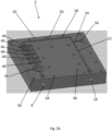
- the main body of the apparatus is provided as an integrally formed piece of material in which some or all of the liquid inlet, at least part of the gas (e.g. oxygen) inlet, at least part of the venturi and at least part of the outlet are formed in the integrally formed piece of material (e.g. the components are provided as an open or closed channel in the integrally formed piece of material).
- the components are provided as an open or closed channel in the integrally formed piece of material.
- the apparatus comprises a liquid source in fluid communication with the liquid inlet and/or a gas (e.g. oxygen) source in fluid communication with the gas (e.g. oxygen) inlet.
- the apparatus may comprise a plurality of liquid sources, each in fluid communication with the liquid inlet (or a plurality of liquid inlets), to allow different types of liquid to be supplied to the apparatus.
- The, e.g. compact, apparatus is preferably portable, such that it is suitable for use in small scale applications, e.g. laboratory based systems, where it can be plugged into the necessary components, as described above, e.g. for supplying the (e.g. oxygenated) liquid to a small scale bioreactor or other consuming device.
- the apparatus may comprise only a single venturi.
- the apparatus comprises a plurality of venturis in fluid communication with, and downstream of, the liquid inlet and the oxygen inlet, wherein the venturis are arranged to dissolve the oxygen into the liquid passing through the venturis, and at least part of the venturis are formed in an integrally formed piece of material.
- Providing multiple venturis increases the flow rate capacity of the device and may increase the amount of gas (e.g. oxygen) which is dissolved in the liquid and thus the concentration of dissolved gas (e.g. oxygen) in the liquid output from the apparatus.
- the plurality of venturis may be arranged in series and/or parallel with each other.
- the apparatus may comprise one or more valves, each valve in fluid communication with, and upstream or downstream of, a respective venturi.
- each valve is arranged to open or close to allow the liquid and the gas (e.g. oxygen) to flow through its respective venturi.
- the gas e.g. oxygen
- the one or more venturis may take any suitable and desired form, e.g. dependent on the size of the device and the desired degree of, e.g., oxygenation.
- the length of the venturi i.e. the length of the restriction in the flow path, is preferably between 5 mm and 150 mm, e.g. between 10 mm and 80 mm, e.g. between 20 mm and 40 mm, e.g. approximately 30 mm.
- the cross section of the venturi i.e. in a plane perpendicular to the direction of the flow path through the venturi, has a shape which may comprise a circle, an oval, a rectangle, or any other suitable and desired shape.
- the depth of the venturi i.e.
- the minimum dimension in a direction substantially perpendicular to the direction of the flow path through the venturi is preferably between 0.01 mm and 10 mm, e.g. between 0.05 mm and 5 mm, e.g. between 0.1 mm and 2 mm, e.g. approximately 1 mm.
- the width of the venturi i.e. the maximum dimension in a direction substantially perpendicular to the direction of the flow path through the venturi, and generally substantially perpendicular to the depth of the venturi, is preferably between 1 mm and 50 mm, e.g. between 5 mm and 20 mm, e.g. approximately 15 mm.
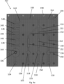
- the apparatus comprises a diffusion chamber in fluid communication with, and downstream of, the gas (e.g. oxygen) inlet (and also the liquid inlet), the diffusion chamber and the gas (e.g. oxygen) inlet being arranged such that the gas (e.g. oxygen) is supplied through the gas (e.g. oxygen) inlet into the diffusion chamber.
- the diffusion chamber provides a volume through which the liquid flows and into which the gas (e.g. oxygen) is injected, with the diffusion chamber being arranged to promote the break-up of bubbles of gas (e.g. oxygen) into smaller bubbles, e.g. by encouraging turbulent flow of the liquid and the gas (e.g. oxygen in the diffusion chamber.
- a grid or mesh e.g.
- the diffusion chamber e.g. through which the gas (e.g. oxygen) and liquid must pass into the diffusion chamber. This helps to break-up the gas (e.g. oxygen) into small bubbles within the liquid so that they are more easily dissolved into the liquid in the diffusion chamber and downstream in the apparatus, e.g. in the venturi.
- the gas e.g. oxygen
- the apparatus comprises a mixing chamber in fluid communication with, and downstream of, the gas (e.g. oxygen) inlet and the liquid inlet (and also the diffusion chamber in the embodiment in which it is provided), the mixing chamber being arranged to induce turbulence into the fluid flowing therethrough.
- the mixing chamber produces turbulent flow of the liquid and the gas (e.g. oxygen) flowing through the mixing chamber which acts to break-up the gas (e.g. oxygen) into small bubbles within the liquid, e.g. smaller than they were broken up into in the diffusion chamber, so that they are more easily dissolved into the liquid in the mixing chamber and downstream in the apparatus, e.g. in the venturi.
- the mixing chamber may be provided in any suitable and desired way, i.e. to induce the necessary turbulent flow.
- the mixing chamber comprises one or more obstacles and/or a tortuous path.
- the obstacles may comprise one or more barriers in the flow path through the mixing chamber, around which the fluid flowing therethrough must pass.
- the gas (e.g. oxygen) inlet, the conduit, the venturi and the outlet, preferably at least part of the mixing chamber and/or at least part of the diffusion chamber is formed in the integrally formed piece of material.
- Providing these components of the apparatus in the same integrally formed piece of material further increases the compact nature of the apparatus that does not contain multiple individually manufactured components, e.g. which need to be connected together with tubes.
- the conduit (between the liquid and the gas (e.g. oxygen) inlets and the venturi), as well as any other conduits or flow paths between the various different components in the apparatus may take any suitable and desired configuration.
- any bends in the conduit(s) and/or flow paths are preferably rounded. This has been found to aid the flow of fluid through the apparatus and reduces the shear and stress on the fluid, which is particularly important in the embodiment used for, e.g., oxygenating a cell culture medium containing cells because this reduces the disturbance and destruction of the cells.
- the arrangement of the various components of the apparatus e.g. the liquid inlet, the gas (e.g. oxygen) inlet, the venturi, the outlet, the diffusion chamber and the mixing chamber) in the integrally formed piece of material, i.e. with at least part of each of the components being formed in the integrally formed piece of material, can be provided in any suitable and desired way.
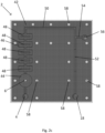
- one or more of the components are formed in the integrally formed piece of material as an open channel in the face of the integrally formed piece of material, wherein the apparatus comprises a blank face of material, such that when the face of the integrally formed piece of material and the blank face of material are placed together in good contact the open channel in the integrally formed piece of material and the blank face of material form the one or more of the components.
- one or more of the components are partly formed as an open channel in the face of the (a first) piece of material and with the remaining part of one or more of the components formed in the corresponding face of a second piece of material such that when the first piece of material and the second piece of material are placed together in good contact, their corresponding open channels form the components.
- the channel formed in the face of the second piece of material is a mirror image of the channel formed in the face of the first piece of material.
- the open channel in the first piece of material and the open channel in the second channel may have different depths, for example.
- one or more of the liquid inlet, the gas e.g.
- oxygen inlet and the outlet may be formed in the opposite face of the first or second piece of material to the face in which the open channel is formed. This may be more convenient for attaching the liquid and/or gas (e.g. oxygen) supply to their respective inlets and/or for conveying the oxygenated liquid from the outlet to a secondary device, e.g. a bioreactor, for the, e.g. oxygenated, liquid to be used.
- a secondary device e.g. a bioreactor
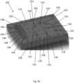
- the apparatus comprises first and second integrally formed pieces of material
- the first and second pieces of material can be attached to each other in any suitable and desired way in order to fully form the various components of the apparatus, e.g. by creating a fluid-tight seal between the first and second pieces of material such that the liquid and oxygen do not escape but flow through the various components of the apparatus.
- Various arrangements of attachment are contemplated by the Applicant which include using one or more clamps, screws, welding or gluing, etc.
- the apparatus comprises a plurality of bolts which pass through and hold together the first and second integrally formed pieces of material.
- one or more of the components are fully formed as a channel through a single piece of material. This allows all the main components of the apparatus to be provided in a single piece of material, enabling it to be provided in a compact and robust manner.
- one or more of the components may be formed by an open channel in the first piece of material and a blank face in the second piece of material
- one or more of the other components may be formed by an open channel in the second piece of material and a blank face in the first piece of material
- one or more of the other components may be formed by an open channel in the first piece of material and a corresponding open channel in the second piece of material and/or one or more of the other components may be fully formed as a channel through the first or second piece of material.
- the single piece of material and/or the first and second pieces of material together forms a block of material, e.g. having a substantially cuboid shape.
- This configuration makes it particularly easy to form the components in the block of material, e.g. by milling the components (e.g. formed as a channel) in the block of material.
- the piece(s) of material may take other shapes as is suitable and desired.
- the piece(s) of material has a substantially cylindrical shape, e.g. pipe shaped, so that the piece(s) of material can be integrated easily into a pipe system.
- the (first and/or second) integrally formed piece of material may have any suitable and desired dimensions.
- the integrally formed piece of material (e.g. the first or second, or the combination of both) has a width dimension of less than 30 cm, e.g. less than 25 cm, e.g. less than 20 cm, e.g. approximately 15 cm, and/or a height dimension of less than 30 cm, e.g. less than 25 cm, e.g. less than 20 cm, e.g. approximately 15 cm, and/or a depth dimension of less than 15 cm, e.g. less than 10 cm, e.g. approximately 7 cm.
- the apparatus is easily portable and can conveniently be connected into an inline system for supplying, e.g. oxygenated liquid, to a downstream consuming device, e.g. a bioreactor or fermentor.
- the piece(s) of material may comprise any suitable and desired material.
- the piece(s) of material comprises stainless steel, e.g. an integrally formed piece of stainless steel.
- Stainless steel allows the various components of the apparatus to be formed in the piece(s) of material and it is a relatively inert material such that very little corrosion of the material will occur during operation (and thus almost no contamination of the liquid flowing therethrough will occur).
- the piece(s) of material comprises diamond. Owing to the hardness of diamond, although it requires specialist machinery to form the various components of the apparatus, once formed the piece of material will be exceptionally durable and will result in no contamination of the liquid flowing therethrough.
- the piece(s) of material are suitable to be placed into an autoclave for sterilisation for subsequent use in the apparatus, e.g. as stainless steel and diamond are.
- the piece(s) of material comprises a polymer, e.g. a thermoplastic polymer.
- a polymer allows the various components, e.g. as a channel through the piece of material, to be formed by moulding the polymer into an appropriate shape.
- the polymer comprises a polymer which is able to be sterilised, either as part of its manufacture, e.g. during moulding, or afterwards prior to use by applying a suitable treatment.
- a further advantage of using a polymer for the piece of material is that the device may be manufactured relatively inexpensively and thus it is suitable for providing a device which is disposable and designed for single use.
- the first and second pieces of material comprise different types of material.
- this could comprise stainless steel, which is conveniently milled to form the various components
- the second piece of material forming the blank face of material could comprise a polymer, e.g. polytetrafluoroethylene (PTFE), which can create a good seal with the stainless steel to form the channel.
- PTFE polytetrafluoroethylene
- the components of the apparatus may be formed in the piece(s) of material in any suitable and desired way, e.g. as is most suitable for the type of material being used. Therefore the various components could be cast or milled (e.g. if the piece(s) of material comprises stainless steel or a polymer), engraved (e.g. if the piece(s) of material comprises diamond), 3-D printed or moulded (e.g. if the piece(s) of material comprises polymer), etched, burned, etc. Any of these manufacturing methods may be suitable for forming apparatus in the embodiment in which it comprises first and second integrally formed pieces of material as well as in the embodiment in which the one or more of the components are fully formed as a channel through a single piece of material. Conveniently, manufacture using computer aided design (CAD) may be used, e.g. a CAD milling machine.
- CAD computer aided design
- the apparatus may be used at any temperature as is desired and is suitable, e.g. the ambient temperature of the liquid being supplied into the apparatus.
- the apparatus could be operated at between approximately 10 degrees Celsius and approximately 12 degrees Celsius, e.g. for hydroponics at high altitude where this is the ambient temperature.
- the apparatus is operated at a temperature of between approximately 20 degrees Celsius and approximately 45 degrees Celsius, e.g. between approximately 25 degrees Celsius and approximately 45 degrees Celsius, which is suitable for cell cultures and media as well as the production of oxygenated liquids for medical applications.
- the apparatus is operated between approximately 35 degrees Celsius and approximately 37 degrees Celsius. This is the ideal temperature for supplying the oxygenated liquid to a bioreactor.
- the apparatus comprises a heater arranged to heat the liquid and/or the gas (e.g. oxygen) (as generally the ambient temperature of the liquid will be below the desired operating temperature of the apparatus).
- the heater may be arranged upstream of the integrally formed piece of material, e.g. arranged to heat the liquid being supplied to the liquid inlet and/or the gas (e.g. oxygen) being supplied to the gas (e.g. oxygen) inlet.
- the liquid and/or the gas (e.g. oxygen) are supplied at the desired temperature to their respective inlets.
- the heater is arranged to heat the integrally formed piece of material, i.e. the liquid and/or the gas (e.g. oxygen) are supplied at a lower temperature to their respective inlets of the apparatus and when the liquid and/or the gas (e.g. oxygen) are inside the apparatus they are heated to the desired operating temperature.
- the heater is arranged in good thermal contact with one or more of: the liquid inlet, the gas (e.g. oxygen) inlet, the conduit, the venturi and the outlet, and the diffusion chamber and the mixing chamber where provided.
- the heater could be arranged in any suitable and desired way with respect to the integrally formed piece of material.
- the heater comprises a heating element, e.g. a thick film or sheathed heating element, in good thermal contact with the integrally formed piece of material, e.g. the heating element may be embedded in the integrally formed piece of material.
- This arrangement of the heater allows the liquid and/or the gas (e.g. oxygen), e.g. the liquid-gas (e.g. oxygen) mixture, to be heated as it flows through the main body of the apparatus.
- the heater is arranged downstream of the integrally formed piece of material, e.g. arranged to heat the, e.g. oxygenated, liquid output from the outlet of the apparatus, before the liquid is supplied for its end use, e.g. into a bioreactor.
- the apparatus may comprise more than one heater, e.g. two or more of: upstream of the integrally formed piece of material, arranged to heat the integrally formed piece of material and downstream of the integrally formed piece of material.
- the liquid is desired to be, e.g. oxygenated, at one temperature and then supplied to a further device, e.g. a bioreactor, at a different temperature.
- the apparatus comprises a chiller arranged to cool the liquid and/or gas (e.g. oxygen), e.g. downstream of the integrally formed piece of material.
- the apparatus is arranged to produce oxygenated liquid with a concentration of dissolved oxygen of greater than 20 mg/I, e.g. greater than 40 mg/I, e.g. greater than 50 mg/I, e.g. greater than 60 mg/I, e.g. approximately 70 mg/l.
- concentrations of dissolved oxygen are achieved when the apparatus is operated at a temperature of greater than 25 degrees Celsius, e.g. greater than 30 degrees Celsius, e.g. greater than 35 degrees Celsius, e.g. at approximately 37 degrees Celsius.
- the concentration of dissolved oxygen able to be achieved depends on the temperature of the liquid flowing through the apparatus, with the achievable concentration generally increasing with decreasing temperature.
- concentrations of dissolved oxygen as high as 60 mg/l at 37 degrees Celsius, for example, the concentration of dissolved oxygen achieved at 25 degrees Celsius may be higher, e.g. 70 mg/l.
- the apparatus may comprise a conduit arranged to recycle a portion of the, e.g. oxygenated, fluid from the outlet to the liquid inlet, with the outlet being arranged to dispense a remaining portion of the oxygenated fluid that is not recycled, e.g. to a bioreactor.
- the conduit has one end in fluid communication with, and downstream of, the outlet, and another end in fluid communication with and upstream of the liquid inlet. Recycling some of the, e.g. oxygenated, liquid may help to increase the concentration of dissolved gas (e.g. oxygen) in the liquid owing to at least some of the liquid passing multiple times through the apparatus before being dispensed.
- at least part of the recycling conduit is formed in the integrally formed piece of material.
- the apparatus is arranged to operate in a single pass production mode, i.e. with no recycling of the, e.g. oxygenated, liquid.
- the apparatus takes the liquid from the liquid inlet, passes it through the apparatus where it is, e.g., oxygenated, and outputs it from the apparatus through the outlet, e.g. to a downstream device, such that the apparatus can simply be connected in between a liquid supply and a device which uses the, e.g. oxygenated, liquid, e.g. a bioreactor.
- the, e.g. oxygenated, fluid may be recycled back to the apparatus after passing through the downstream consuming device, e.g. the bioreactor.
- the apparatus may comprise a conduit arranged to recycle the, e.g. oxygenated, fluid from a downstream consuming device, e.g. the bioreactor, to the liquid inlet of the apparatus.
- the apparatus comprises a gas/liquid separator downstream of and in fluid communication with the outlet, wherein the gas/liquid separator is arranged to separate undissolved oxygen (or other gases) from the (de-)oxygenated liquid.
- the gas/liquid separator is arranged to separate undissolved oxygen (or other gases) from the (de-)oxygenated liquid.
- This allows bubbles of oxygen (or other gases) to be removed from the, e.g. oxygenated, liquid, e.g. in circumstances when they are not desired or where large amounts of undissolved gas is present.
- bubbles may be detrimental to the production of cell cultures, or if the, e.g. oxygenated, liquid is being used intravenously it will be dangerous for bubbles of gas (e.g. oxygen) to be present.
- bubbles of gas (e.g. oxygen) in the, e.g. oxygenated, liquid can be tolerated or even preferred, e.g. to encourage the release of carbon dioxide in a bioreactor, and thus a gas/liquid separator may not be
- the apparatus also comprises a gas recycling conduit for recycling undissolved gas (e.g. oxygen) back to the gas inlet.
- a gas recycling conduit for recycling undissolved gas (e.g. oxygen) back to the gas inlet. This helps to minimise the waste of undissolved gas and thus reduces the cost of the gas used in the process.
- the apparatus may comprise a filter to remove additives or other unwanted substances from the liquid, either upstream of the liquid inlet or downstream of the outlet, i.e. before or after, e.g., oxygenation of the liquid, or even within the main body of the apparatus, i.e. the integrally formed piece of material.
- the apparatus comprises means to remove carbon dioxide from the liquid, e.g. a carbon dioxide scrubber, a carbon dioxide stripper, etc.
- the carbon dioxide removal means can be positioned in any suitable and desired place within the apparatus, e.g. upstream of the liquid inlet, downstream of the outlet or within the main body of the apparatus.
- Removal of carbon dioxide from the liquid may be desired, for example, when the, e.g. oxygenated, liquid is being fed to a bioreactor, with the carbon dioxide which is produced by the cells in the bioreactor needing to be removed before the liquid is recycled, for example, back to the bioreactor via the apparatus for, e.g., (re-)oxygenation.
- the apparatus comprises an additive inlet, either upstream of the liquid inlet or downstream of the outlet, arranged to supply one or more additives into the liquid.
- a filter and/or an additive supply may depend on the use of the, e.g. oxygenated, liquid.
- nutrients may be added to the liquid before supplying the, e.g. oxygenated, liquid to a bioreactor, so that the cells being cultured in the bioreactor are suitably nourished, or nutrients or other additives may be added to the liquid before supplying the, e.g. oxygenated, liquid intravenously.
- the liquid supplied to the apparatus may already contain the desired additives, e.g. added during the preparation of the liquid.
- the liquid may be flowed through the apparatus in any suitable and desired way.
- the pressure of the incoming liquid owing to gravity e.g. an elevated tank of liquid compared to the apparatus, could be employed to drive the liquid through the apparatus.
- This may be convenient when the apparatus is being used to deliver oxygenated liquid for intravenous use, for example.
- the apparatus comprises a liquid inlet pump in fluid communication with and upstream of the liquid inlet, wherein the liquid inlet pump is arranged to pump the liquid through the apparatus.
- the liquid inlet pump is external to the integrally formed piece of material and therefore can be provided as a separate, e.g., off-the-shelf, component.
- the liquid inlet pump may comprise any suitable and desired type of pump, e.g. a magnetic drive pump (e.g. such as the PuraLev (RTM) series from Levitronix (RTM)), a positive displacement pump (e.g. a roller ball pump or a peristaltic pump).
- a magnetic drive pump e.g. such as the PuraLev (RTM) series from Levitronix (RTM)
- a positive displacement pump e.g. a roller ball pump or a peristaltic pump
- the liquid inlet pump comprises a gear pump, e.g. an external gear pump, such as the GJR series of Micropump (RTM).
- the gas e.g. oxygen
- the gas may be supplied into the apparatus in any suitable and desired way.
- the oxygen may be supplied into the apparatus in a liquid and/or a gaseous form.
- the apparatus comprises a pressurised oxygen supply, e.g. a pressurised gas cylinder containing oxygen, in fluid communication with the oxygen inlet.
- the gas may comprise any suitable and desired type of gas, e.g. nitrogen, argon, chlorine or carbon dioxide (as well as oxygen as outlined above).
- the apparatus comprises a gas source in fluid communication with the gas inlet.
- a gas source in fluid communication with the gas inlet.
- specific references herein to components relating to oxygen are also applicable to any suitable and desired gas that may be used with the apparatus.
- the apparatus comprises a plurality of gas (e.g. oxygen) inlets.
- Each gas inlet may be connected to the same gas source or to separate gas sources, the latter of which may supply the same or different types of gas to the multiple gas inlets.
- a plurality of gas inlets may be provided in an apparatus having a single venturi, e.g. in order to introduce a plurality of different gases into the liquid flow.
- an apparatus comprising a plurality of gas inlets may comprise a plurality of venturis. Two or more, but preferably all, of the venturis may have a gas inlet arranged upstream of the respective venturi to introduce the gas from the respective gas inlet (and gas source) into the liquid flow. This arrangement allows different gases (or different amounts of the same gas) to be introduced into the liquid flow upstream of each of the venturis when, e.g., a mix of different gases is desired to be dissolved into or displaced from the liquid.
- a further embodiment in which a plurality of gas inlets is provided is in a system comprising a plurality of apparatuses, e.g. arranged in series or parallel, as described below.
- each apparatus may have one or a plurality of gas inlets.
- the apparatus comprises a plurality of liquid inlets.
- the plurality of liquid inlets may be connected to the same liquid source or to separate liquid sources, the latter of which may supply the same or different types of liquids to the multiple liquid inlets.
- a plurality of liquid inlets may be provided in an apparatus having a single venturi, e.g. in order to dissolve gas into a plurality of different liquids.
- an apparatus comprising a plurality of liquid inlets may comprise a plurality of venturis.
- Two or more, but preferably all, of the venturis may have a liquid inlet arranged upstream of the respective venturi to introduce the liquid from the respective liquid inlet (and liquid source) into the apparatus.
- This arrangement allows different to be introduced into the apparatus upstream of each of the venturis when, e.g., a mix of different liquids is desired to have gas dissolved into or displaced from the liquid.
- a further embodiment in which a plurality of liquid inlets is provided is in a system comprising a plurality of apparatuses, e.g. arranged in series or parallel, as described below.
- each apparatus may have one or a plurality of liquid inlets.
- the apparatus may comprise a plurality of gas inlets and a plurality of liquid inlets, e.g. if a mix of different gases is desired to be dissolved into or displaced from a plurality of different liquids.
- the gas (other than oxygen) comprises nitrogen.
- Nitrogen has a number of advantages, particularly that it can be used to deplete the liquid of oxygen, by displacing oxygen from the liquid, but also that it is abundant, cheap and easy to work with. Nitrogen (or gases other than oxygen) can therefore be used to control the oxygen concentration in a liquid, e.g. to provide a liquid (e.g. a cell medium to a bioreactor) with a low oxygen concentration.
- the gas comprises a flammable gas, e.g. for use in biorefining.
- liquid when a low oxygen concentration is required, e.g. in some bioreactors, if the liquid is in fluid communication with ambient air then the oxygen concentration will increase, drifting towards equilibrium with the ambient air, necessitating regular de-oxygenation of the liquid to maintain its oxygen concentration at the desired level.
- stem cells are better grown in a medium having a low oxygen concentration during one phase of culturing the cells.
- the flow rate of the liquid through the apparatus may be any suitable and desired value or range of values, e.g. depending on the end use of the oxygenated liquid.
- the apparatus is arranged to deliver a flow rate of oxygenated liquid of between 0.01 ml/min and 100 l/min from the outlet of the apparatus, e.g. between 0.1 ml/min and 50 l/min, e.g. between 1 ml/min and 20 l/min, e.g. between 5 ml/min and 5 I/min. Therefore preferably the liquid inlet pump is arranged to deliver a flow rate of between 0.01 ml/min and 100 l/min, e.g. between 0.1 ml/min and 50 l/min, e.g.
- a flow rate of 0.01 ml/min may be required for intravenous use of the oxygenated liquid, e.g. where this is supplied directly to a patient, whereas a flow rate of 50 l/min may be required for use of the oxygenated liquid in a bioreactor.
- the pressure of the liquid flowing through the apparatus may be any suitable and desired value or range of values.
- the apparatus is arranged to operate at a fluid pressure of between 0.1 and 5 bar, e.g. between 0.5 and 4 bar, e.g. approximately 3 Bar.
- the liquid inlet pump is arranged to deliver a pressure of between 0.1 and 5 bar, e.g. between 0.5 and 4 bar, e.g. approximately 3 Bar.
- liquid is to be taken to mean liquids in the conventional sense as well as gels which are flowable, i.e. that behave as liquids.
- the apparatus is arranged to be used with any such liquids as is suitable and desired, e.g. for the particular use of the, e.g. oxygenated, liquid.
- a non-limiting list of liquids that could be used with the apparatus include: water, (whole) blood or any component of blood (e.g. plasma), cell suspensions, cell media, phosphate buffered saline (e.g. an isotonic solution), physiological solutions, flowable gels, contact lens solutions, anti-septic liquids, buffers and milk.
- Liquids suitable for use as cell culture media may include one or more of the following components: minerals, carbon sources (such as saccharides (e.g. mono, di, oligo and polysaccharides, especially mono and disaccharides)), nitrogen sources (e.g. nitrates, proteins or protein fragments, ammonium compounds, oligopeptides, amino acids (especially essential amino acids, e.g. tryptophan and/or glutamine)), nucleic acids and nucleic acid fragments, lipids, etc.
- the liquid contains glucose and added nitrate and mineral salts (e.g.
- the liquid contains one or more vitamins, e.g. folic acid, nicotinamide, riboflavin, B 12 .
- the liquid may contain fetal bovine serum (FBS) but preferably the liquid contains one or more non-ionic triblock copolymers, e.g. poloxamers, which help to promote cell survival, growth, production, etc..
- the concentrations of the various components of the liquid may be any suitable and desired concentrations, e.g. to suit the application for which the liquid is being used.
- the concentration of poloxamer in the liquid is preferably between 1% and 20% of the total volume, e.g. between 2% and 15%, e.g. 4% or 14%.
- the concentration of poloxamer in the liquid may depend on the type of the cell culture medium being used.
- the cell culture medium may comprise any suitable and desired cell culture medium, for example Eagle's minimal essential medium (EMEM).
- EMEM Eagle's minimal essential medium
- the cell culture medium comprises Dulbecco's modified Eagle's medium (DMEM), e.g. containing 4% poloxamer.
- DMEM Dulbecco's modified Eagle's medium
- the cells used may comprise any suitable and desired cells, e.g. any living organism for culture in the downstream consuming device, e.g. a bioreactor or fermentor.
- the cells in the cell suspension or for use with the cell media comprise one or more of insect cells, anaerobic and/or aerobic bacteria, Escherichia coli (E. coli), fungi (e.g. yeast) and animal cells, e.g. mammalian cells.
- the apparatus comprises a pressure sensor arranged to measure the pressure of the liquid in the apparatus, and/or an oxygen sensor arranged to measure the concentration of dissolved oxygen in the liquid, and/or a flow rate sensor, e.g. a flow meter, arranged to measure the flow rate of the liquid through the apparatus, and/or a temperature sensor arranged to measure the temperature of the liquid in the apparatus.
- a pressure sensor arranged to measure the pressure of the liquid in the apparatus
- an oxygen sensor arranged to measure the concentration of dissolved oxygen in the liquid
- a flow rate sensor e.g. a flow meter
- the various sensors may be positioned to measure their respective variables at any suitable point in the apparatus.
- the pressure sensor is preferably positioned between the liquid inlet and the venturi, e.g. downstream of the mixing chamber in the embodiments in which this is provided.
- the oxygen sensor is positioned downstream of the venturi.
- the temperature sensor is positioned downstream of the heater, in the embodiments which comprise a heater.
- the temperature sensor is arranged to provide feedback to the heater (e.g. such that the heater can be operated, based on the feedback, to control the temperature of the liquid in the apparatus, e.g. to maintain it at a particular temperature), and/or the flow rate sensor is arranged to provide feedback to the liquid inlet pump (e.g. such that the pump can be operated, based on the feedback, to control the flow rate of the liquid through the apparatus, e.g.
- the oxygen sensor is arranged to provide feedback to one or more of: the oxygen supply, the liquid inlet pump and the heater (e.g. such that one or more of the gas, e.g. oxygen, supply, the liquid inlet pump and the heater can be operated, based on the feedback, to control their operation, e.g. to maintain the gas, e.g. oxygen, concentration of the liquid at a particular gas, e.g. oxygen, concentration).
- the gas e.g. oxygen, supply, the liquid inlet pump and the heater
- the heater e.g. such that one or more of the gas, e.g. oxygen, supply, the liquid inlet pump and the heater can be operated, based on the feedback, to control their operation, e.g. to maintain the gas, e.g. oxygen, concentration of the liquid at a particular gas, e.g. oxygen, concentration.
- the apparatus comprises a control arranged to receive the measurements output from one or more (and preferably all) of the sensors and to send control signals to the respective components with which the sensors are arranged to provide feedback to.
- the measurements from the flow rate sensor are received by the control which then sends an appropriate control signal to the liquid inlet pump, e.g. by changing the input voltage to the pump, or to the plurality of valves, e.g. such that the flow rate of the liquid through the apparatus can be controlled, e.g. to maintain it at a particular flow rate.
- This feedback and control provides regulation of the various different variables within the apparatus.
- the cross sectional area of the flow path through the apparatus may be chosen, e.g. during manufacture of the apparatus, to control the flow rate of the liquid through the apparatus. This may be relevant for applications of the apparatus for intravenous use, for example, in which gravity is used to drive the liquid through the apparatus.
- the apparatus may comprise a flow rate sensor, e.g. a flow meter, to provide feedback, e.g. to a control, of the flow rate of the liquid passing through the apparatus.
- the apparatus may be used to supply, e.g. oxygenated, liquid for any suitable and desired use.
- one particularly preferred use is to supply the, e.g. oxygenated, liquid to a bioreactor.
- Another use is to supply the, e.g. oxygenated, liquid for intravenous use, e.g. for a therapeutic use.
- the apparatus is arranged to operate continuously, e.g. to continuously supply, e.g. oxygenated, liquid to flow through a bioreactor or through an intravenous cannula.
- the apparatus comprises a conduit in fluid communication with, and downstream of, the outlet, the conduit being arranged to supply the output, e.g. oxygenated, liquid to an external device, e.g. a bioreactor.
- the system comprises a downstream consuming device, e.g. a bioreactor, wherein the outlet of the apparatus is in fluid communication with the downstream consuming device such that, e.g. oxygenated, liquid can be supplied to the downstream consuming device.
- a downstream consuming device e.g. a bioreactor
- the downstream consuming device comprises a bioreactor
- the downstream consuming device to which the liquid is output may comprise any suitable and desired device.
- the downstream consuming device may comprise a fermentor, a high-performance liquid chromatography (HPLC) device or a device to stabilise one or more components of a fluid, e.g. using an oxygenated or de-oxygenated liquid.
- HPLC high-performance liquid chromatography
- Such a system supplying, e.g. oxygenated, liquid for a downstream consuming use may comprise a single apparatus.
- a plurality of such apparatuses may, for example, be arranged in series and/or parallel, with the, e.g. oxygenated, liquid output from the plurality of apparatuses being supplied to the downstream consuming device.
- Such an arrangement may increase the flow rate capacity of the system, i.e. increase the flow rate of liquid having gas dissolved therein, e.g. being oxygenated, and thus the flow rate of, e.g. oxygenated, liquid being supplied from the apparatus.
- the apparatus and/or system comprises a holding volume for the, e.g. oxygenated, liquid, wherein the holding volume is in fluid communication with and downstream of the outlet, and preferably also in fluid communication with and upstream of the liquid inlet, of the apparatus, e.g. via appropriate conduits.
- the holding volume is in fluid communication with and downstream of the outlet, and preferably also in fluid communication with and upstream of the liquid inlet, of the apparatus, e.g. via appropriate conduits.
- the liquid inlet, at least part of the gas inlet, at least part of the venturi and at least part of the outlet are formed in an integrally formed piece of material.
- the gas comprises oxygen and the gas inlet comprises an oxygen inlet for supplying oxygen into the liquid within the apparatus.
- Providing a holding volume for the, e.g. oxygenated, liquid allows the apparatus or system to maintain a certain amount of, e.g. oxygenated, liquid that is available for supplying to a downstream consuming device, for example, so that liquid can be provided whenever it is required, e.g. on demand, without having to be constrained by the flow rate of the liquid through the venturi, for example.
- the oxygen concentration of the liquid in the holding volume is therefore preferably maintained at a suitable and desired level, e.g. for supplying to a downstream consuming device, where provided as part of a system.
- the holding volume may have any suitable and desired volume.
- the holding volume has an internal volume between 500 ml and 20 I, e.g. between 1 l and 10 l, e.g. between 2 I and 5 I.
- the size of the holding volume may depend on the size of the downstream consuming volume.
- the size of the holding volume is proportional to the size of the downstream consuming volume.
- the holding volume is also in fluid communication with an inlet, and preferably also an outlet, of the downstream consuming device, where provided as part of a system, e.g. via appropriate conduits.
- This allows the, e.g. oxygenated, liquid to be provided to the downstream consuming device and also recycled, when necessary, e.g. on demand.
- Such connections may therefore be provided instead of (but could also be provided as well as) the direct connections described above between the apparatus and the downstream consuming device, e.g. the outlet from the oxygenating part of the apparatus and the downstream consuming device may be connected via the holding volume.
- the holding volume may contain a self-sufficient volume of liquid for the requirements of the apparatus, e.g. the holding volume may comprise the liquid source for supplying to the liquid inlet, but preferably the holding volume comprises a liquid inlet for supplying liquid into the holding volume, e.g. which is in fluid communication with a liquid source, e.g. a feeder tank.
- the apparatus and/or system may comprise a plurality of liquid sources, each in fluid communication with the liquid inlet (or a plurality of liquid inlets) of the holding volume, to allow different types of liquid to be supplied to the holding volume.
- the liquid source e.g. the feeder tank
- the liquid source is preferably in fluid communication with (e.g. via one or more conduits) the downstream consuming device, e.g. to supply liquid to the downstream consuming device and/or to recycle liquid back to the liquid source.
- These connections may be direct between the liquid source and the downstream consuming device, though preferably they are via the holding volume.
- the connections between the various components of the apparatus and/or system may be arranged such that the liquid is flowed through the apparatus and/or system in any suitable and desired way, e.g. using gravity to drive the liquid through the apparatus and/or system.
- the apparatus and/or system preferably comprises one or more pumps arranged to pump the liquid through the apparatus and/or system.
- the liquid inlet pump described above in fluid communication with and upstream of the liquid inlet of the (oxygenating part of the) apparatus, which is arranged to pump the liquid through the apparatus, is preferably also in fluid communication with and downstream of the holding volume, and is arranged to pump liquid from the holding volume to the liquid inlet of the apparatus.
- the liquid inlet pump between the holding volume and the liquid inlet of the apparatus is sufficient to pump the liquid through the apparatus and back to the holding volume, though a further pump may be provided, e.g. between the outlet of the apparatus and the holding volume if necessary.
- the apparatus and/or system comprises a liquid source pump in fluid communication with and downstream of the liquid source (and thus in fluid communication with and upstream of the holding volume) which is arranged to pump liquid from the liquid source to the holding volume.
- the system comprises an outlet pump in fluid communication with and downstream of the holding volume (and thus in fluid communication with and upstream of the downstream consuming device) which is arranged to pump liquid from the holding volume to the downstream consuming device.
- the downstream consuming device is arranged to recycle liquid back to the holding volume (or other part of the system)
- the system comprises a recycling pump in fluid communication with and downstream of the downstream consuming device (and thus in fluid communication with and upstream of the holding volume) which is arranged to pump liquid from the downstream consuming device to the liquid source.
- this latter recycling pump may be the same as or as well as the liquid pump (as described above) between the liquid source and the holding volume.
- the various pumps described may each comprise any suitable and desired type of pump, e.g. a magnetic drive pump, a positive displacement pump (e.g. a roller ball pump or a peristaltic pump) but, as described above, preferably one or more (and preferably all) of the pumps comprise a gear pump, e.g. an external gear pump.
- a magnetic drive pump e.g. a magnetic drive pump
- a positive displacement pump e.g. a roller ball pump or a peristaltic pump
- gear pump e.g. an external gear pump.
- the holding volume may comprise any suitable and desired container for the, e.g. oxygenated, liquid, with the necessary connections to the apparatus and the downstream consuming device, where provided.
- the holding volume may comprise a flexible polymer bag (e.g. similar to those used for intravenous fluids), but preferably the holding volume comprises a rigid container, e.g. a glass or rigid polymer container.
- a rigid container is better suited for containing a build-up of pressure in the apparatus or system.
- the holding volume comprises a vent in fluid communication with the atmosphere outside of the holding volume.
- This helps the holding volume to control the atmosphere and the pressure inside the holding volume e.g. as the holding volume may comprise a volume greater than that of the liquid therein and may thus also contain a volume of gas, e.g. air.
- the vent may comprise any suitable and desired type of vent.
- the vent may be active and thus able to actively control the pressure and composition of the atmosphere inside the holding volume, however preferably the vent is passive.
- the vent comprises a filter, e.g. comprising nylon and/or other polymers, for example in the form of a flat disc in a wall of the holding volume.
- the holding volume comprises an agitator for stirring the liquid in the holding volume.
- This maintains the homogeneity of the liquid and thus the oxygen (or other gas) concentration thereof, particularly if the liquid inlets to the holding volume, e.g. from the liquid source, the liquid outlet of the apparatus and the downstream consuming device, are supplying liquid into the holding volume at different positions, e.g. levels.
- the holding volume comprises an oxygen sensor arranged to measure the concentration of dissolved oxygen in the liquid in the holding volume, e.g. instead of or as well as the oxygen sensor in the apparatus described above.
- an oxygen sensor arranged to measure the concentration of dissolved oxygen in the liquid in the holding volume, e.g. instead of or as well as the oxygen sensor in the apparatus described above. This enables the concentration of dissolved oxygen in the liquid within the holding volume to be controlled, e.g. by passing it through the apparatus to (re-)oxygenate the liquid, if the oxygen concentration in the liquid in the holding volume is detected to have fallen below a particular threshold, e.g. 50 mg/l.
- the downstream consuming device comprises an oxygen sensor arranged to measure the concentration of dissolved oxygen in the liquid in the downstream consuming device, e.g. instead of or as well as the oxygen sensor in the apparatus and/or holding volume described above.
- an oxygen sensor arranged to measure the concentration of dissolved oxygen in the liquid in the downstream consuming device, e.g. instead of or as well as the oxygen sensor in the apparatus and/or holding volume described above. This enables the concentration of dissolved oxygen in the liquid within the downstream consuming device to be controlled, e.g. by having more liquid from the holding volume or apparatus supplied into the downstream consuming device, or increasing the rate of liquid being supplied from the holding volume or apparatus, if the oxygen concentration in the liquid in the downstream consuming device is detected to have fallen below a particular threshold.
- the oxygen sensor in the holding volume is independent of the oxygen sensor in the downstream consuming device and vice versa.
- the holding volume comprises a level sensor, e.g. a capacitive proximity liquid sensor, arranged to measure the level of the liquid in the holding volume.
- a level sensor e.g. a capacitive proximity liquid sensor
- the holding volume comprises a conductivity sensor, e.g. a continuity probe, to measure the conductivity of the liquid in the holding volume.
- a conductivity sensor e.g. a continuity probe
- concentration of electrolytes in the liquid to be measured, thus giving an indication of the amount of minerals and/or salts, for example, in the liquid in the holding volume.
- concentration of electrolytes in the liquid in the holding volume to be controlled, e.g. by having more liquid from the liquid source supplied into the holding volume and/or adding the required electrolytes, e.g. minerals and/or salts, if the conductivity of the liquid in the holding volume is detected to have fallen below a particular threshold.
- foam is produced, e.g. under certain operating conditions.
- liquid e.g. cell culture media
- foam is produced, e.g. under certain operating conditions.
- One reason for this is owing to micro-bubbles being released into the liquid as the liquid passes through the apparatus and/or system, which may occur in certain operating conditions.
- the production of foam can be a problem if the liquid is to be supplied to a downstream consuming device, e.g. a bioreactor, as the foam may have a deleterious effect on the use of the, e.g. oxygenated, liquid.
- the presence of foam may disturb the cells or organisms present in the liquid, limiting the production, and in some cases leading to the death, of the cells or organisms being cultured.
- the system comprises means for reducing foam in the liquid.
- Providing foam reducing means helps to prevent the production of foam and/or reduce, e.g. disperse, the amount of foam when produced.
- the foam reducing means may comprise any suitable and desired arrangement and may be provided in any suitable and desired location within the apparatus and/or system.
- the holding volume comprises the foam reducing means.
- the foam reducing means comprises an ultra-sonic emitter arranged to emit ultrasound waves, e.g. into the holding volume.
- an ultra-sonic emitter helps to disperse or prevent any foam that is produced, e.g. from the liquid passing through the apparatus, e.g. the venturi, and which thus may be present when the liquid is output to the holding volume or the downstream consuming device, for example.
- the frequency and/or amplitude at which the ultra-sonic emitter is arranged to emit the ultrasound waves can be controlled, so that the ultra-sonic emitter can be tuned to suit the conditions, e.g. the type and/or amount of foam present and/or being produced.
- the foam reducing means comprises means for reducing or stopping the flow of liquid through the apparatus, e.g. by reducing the flow rate produced by one or more of the pumps or stopping the one or more of the pumps (e.g. the liquid inlet pump between the holding volume and the apparatus).
- the foam reducing means comprises means for reducing or stopping the flow of liquid through the apparatus, e.g. by reducing the flow rate produced by one or more of the pumps or stopping the one or more of the pumps (e.g. the liquid inlet pump between the holding volume and the apparatus).
- the foam reducing means comprises means for reducing or stopping the flow of gas, e.g. oxygen, into the apparatus, e.g. by reducing or stopping the flow rate of gas through the gas inlet of the apparatus, e.g. by controlling a valve between the gas source and the gas inlet.
- gas e.g. oxygen
- the foam reducing means comprises means for reducing or stopping the flow of gas, e.g. oxygen, into the apparatus, e.g. by reducing or stopping the flow rate of gas through the gas inlet of the apparatus, e.g. by controlling a valve between the gas source and the gas inlet.
- the foam reducing means comprises means for increasing the pressure of the liquid in the apparatus and/or system. Increasing pressure helps to reduce the foam being or that has been produced, e.g. by suppressing the production of micro-bubbles in the apparatus and/or system.
- the pressure may be increased at any suitable and desired part of the apparatus and/or system and in any suitable and desired way.
- the (e.g. so-called "process") pressure is increased within the apparatus for dissolving gas into the liquid, e.g. by increasing the pressure applied by the liquid inlet pump which is arranged to pump the liquid through the apparatus, e.g. into the liquid inlet.
- the (e.g. process) pressure may also be increased by restricting or stopping the flow of liquid within the apparatus, e.g. using the one or more valves fluid communication with the venturis.
- the (e.g. process) pressure may also be increased by increasing the flow of gas, e.g. oxygen, through the gas inlet, e.g. by controlling a valve at the gas inlet.
- the system comprises a valve downstream of the outlet of the apparatus, e.g. between the outlet of the apparatus and the holding volume, e.g. at the outlet of the apparatus, arranged to restrict or stop the flow of liquid therethrough.
- the valve can then be controlled, e.g. at least partially closed, to increase the (e.g. so-called "back-up") pressure within the apparatus.
- the valve may comprise any suitable or desired type of valve, e.g. a needle valve.
- a further benefit of increasing the pressure within the apparatus is that the Applicants have found it to increase the resultant concentration of the gas, e.g. oxygen, which is dissolved into the liquid in the apparatus.
- the pressure of the liquid in the apparatus and/or system can therefore be tuned to optimise the uptake of gas into the liquid and to reduce the amount of foam being produced.
- the (e.g. back-up) pressure within the apparatus e.g. created by the valve between the outlet of the apparatus and the holding volume (instead of or as well as the pressure generated by the liquid inlet pump into the apparatus), is greater than 0.5 bar, e.g. greater than 1 bar, e.g. greater than 1.5 bar, e.g. greater than 2 bar, e.g. greater than 2.5 bar.
- the valve is arranged to operate such that the pressure of the output liquid downstream from the valve is at atmospheric pressure.
- the output liquid is supplied to the downstream consuming device, and the downstream consuming device is arranged to operate, such that there is no build-up of pressure, e.g. the downstream consuming device is arranged to operate at atmospheric pressure.
- the pressure is increased within the holding volume, e.g. by controlling the vent in the holding volume.
- the vent in the holding volume may be closed or restricted to increase the pressure within the holding volume to prevent or reduce any foam.
- the apparatus and/or system comprises means for venting excess gas from the apparatus and/or system.
- the venting means may comprise any suitable and desired arrangement, e.g. a pressure relief valve.
- the pressure relief valve may be positioned in any suitable and desired location in the apparatus and/or system, e.g. within the apparatus.
- the venting means comprises a plenum chamber downstream of the outlet of the apparatus (and preferably also upstream of the holding volume), wherein the plenum chamber comprises a pressure relief valve for venting excess gas from the apparatus.
- the pressure relief valve may comprise any suitable and desired type of valve, e.g. a mechanical valve (e.g. comprising a spring release) or electromechanical valve.
- the pressure relief valve may be actuated automatically, e.g. when a particular pressure is exceeded, or it may be controlled using the pressure in the apparatus measured by a pressure sensor, e.g. the pressure sensor described above which is arranged to measure the pressure of the liquid in the apparatus or by a separate pressure sensor which is arranged to measure the pressure of the excess gas in the apparatus.
- the holding volume comprises a foam sensor arranged to detect the presence of foam in the holding volume. This enables foam to be detected so that the foam can be reduced and/or prevented, e.g. by operating the foam reducing means.
- the liquid level sensor in the holding volume may be arranged to operate as a foam sensor, e.g. as well as a liquid level sensor, but preferably a separate foam sensor is provided.
- the foam sensor may comprise any suitable and desired sensor to detect the presence of foam.
- the foam sensor comprises a level sensor, e.g. in addition to the liquid level sensor.
- the foam level sensor preferably comprises a capacitive proximity sensor which is arranged to detect the presence of foam in the holding volume.
- the holding volume comprises two level sensors, one arranged to measure the level of the liquid in the holding volume and another to detect the presence of foam in the holding volume, e.g. to detect the excess production of foam so that the vent (when provided) is not blocked.
- the two level sensors are arranged at different heights in the holding volume, e.g. the liquid level sensor above the foam level sensor.
- one or both of the level sensors are arranged to measure when liquid and foam respectively is present at the level they are positioned.
- the other sensors which are arranged in the apparatus and/or system may be positioned to measure their respective variables at any suitable point in the apparatus and/or system. Providing one or more, preferably all, of these sensors allows the respective variables to be measured. This enables feedback to be performed in order to optimise the performance of the apparatus and/or provides quality control.
- the holding volume's oxygen sensor is arranged to provide feedback to the liquid inlet pump between the holding volume and the liquid inlet of the apparatus (e.g. such that the liquid inlet pump can be operated, based on the feedback, to pump more liquid through the apparatus to control the dissolved gas concentration in the liquid in the holding volume, e.g. at a particular value).
- the downstream consuming device's oxygen sensor is arranged to provide feedback to the outlet pump downstream of the holding volume and upstream of the downstream consuming device (e.g. such that the outlet pump can be operated, based on the feedback, to pump more liquid from the holding volume to the downstream consuming device, to control the dissolved gas concentration in the liquid in the downstream consuming device, e.g. to maintain it at a particular value).
- the level sensor e.g. the liquid level sensor
- the level sensor is arranged to provide feedback to the liquid source pump between the liquid source and the holding volume (e.g. such that the liquid source pump can be operated, based on the feedback, to control the level of the liquid in the holding volume, e.g. to maintain it at a particular level).
- the conductivity sensor is arranged to provide feedback to the liquid source pump between the liquid source and the holding volume (e.g. such that the liquid source pump can be operated, based on the feedback, to control the electrolyte concentration of the liquid in the holding volume, e.g. to maintain it at a particular value).
- the pressure sensor is arranged to provide feedback to the pressure relief valve (e.g. such that the pressure relief valve can be actuated, based on the feedback, to vent excess gas in the apparatus to control the pressure in the apparatus, e.g. to maintain it at a particular level).
- the foam sensor is arranged to provide feedback to the foam reducing means (e.g. such that the foam reducing means can be operated, based on the feedback, to reduce the foam in the system).
- the foam reducing means comprises multiple components, e.g. an ultra-sonic emitter, means for reducing or stopping the flow of liquid through the apparatus, means for reducing or stopping the flow of gas into the apparatus, and/or means for increasing the pressure of the liquid in the apparatus and/or system
- the foam sensor may be arranged to provide feedback to one or more of the ultra-sonic emitter, the means for reducing or stopping the flow of liquid through the apparatus, and/or the means for increasing the pressure of the liquid in the apparatus and/or system.
- the apparatus and/or system comprises a control arranged to receive the measurements output from one or more (and preferably all) of the sensors and to send control signals to the respective components with which the sensors are arranged to provide feedback to, e.g. the feedback is provided from the sensors to the respective components via the control.
- This may be a different, but preferably the same, control as described above with reference to the apparatus.
- the measurements from the foam sensor are received by the control which then sends an appropriate control signal to the foam reducing means, e.g. by activating the ultra-sonic emitter.
- This feedback and control provides regulation of the various different variables within the apparatus.
- Fig. 1 shows a schematic diagram of a system including an apparatus 1 according to an embodiment of the present invention.
- Solid lines indicate the flow of fluids, i.e. liquid or oxygen, through appropriate conduits, and dashed lines indicate the transfer of information, e.g. control signals.
- the apparatus 1 includes an oxygenation device 2 that has a liquid inlet 4 and an oxygen inlet 6.
- Liquid e.g. cell culture media
- a pump 10 e.g. a gear pump.
- Oxygen is supplied into the oxygen inlet 6 from an oxygen source 14, e.g. a pressurised gas canister of oxygen.
- the oxygenation device 2 includes a heater 16 arranged to heat the liquid supplied to the oxygenation device 2 via the liquid inlet 4, and an outlet 18 for oxygenated liquid.
- the outlet 18 supplies the oxygenated liquid to a bioreactor 20.
- Oxygenated liquid which has been used by the bioreactor 20 is returned to the oxygenation device 2 via a recycling conduit 22 and the pump 10.
- An oxygen sensor 24 is arranged to measure the concentration of dissolved oxygen in the oxygenated liquid output from the oxygenation device 2 through the outlet 18.
- the dissolved oxygen concentration measurements are sent to a control 26 via a wire 28.
- a flow meter 25 is arranged to measure the flow rate of the oxygenated liquid output from the oxygenation device 2 through the outlet 18.
- the flow rate measurements are sent to the control 26 via a wire 27.
- a temperature sensor 29 is arranged to measure the temperature of the liquid flowing through the oxygenation device 2, downstream of the heater 16.
- the temperature measurements are sent to the control 26 via a wire 30.
- a pressure sensor 32 is arranged to measure the pressure of the liquid flowing through the oxygenation device 2.
- the pressure measurements are sent to the control 26 via a wire 34.
- the control is connected to the oxygen source 14, the heater 16 and the pump 10 by respective wires 36, 38, 40 and is arranged to communicate with these components using control signals sent along the wires 36, 38, 40.
- Figs. 2a and 2b show perspective views of the oxygenation device 2 according to an embodiment of the present invention
- Fig. 2c shows a plan view of the oxygenation device 2 shown in Figs. 2a and 2b
- the oxygenation device 2 is made from a block of stainless steel 42 which has had the various components milled into its face using a CAD milling machine.
- the oxygenation device 2 has the liquid inlet 4 formed in a side of the stainless steel block 42 which is in fluid communication of a downstream cylindrical diffusion chamber 44.
- a conduit (not shown) is connected to the liquid inlet 4 to supply the liquid into the oxygenation device 2 from the liquid source via the pump 10.
- the oxygen inlet 6 is formed as a hole in the base of the diffusion chamber 44, i.e. through the rear of the stainless steel block 42.
- a conduit (not shown) is connected to the oxygen inlet 6 to supply the oxygen into the diffusion chamber 44 from the oxygen source.
- a mixing chamber 46 Downstream of, and in fluid communication with, the diffusion chamber 44 is a mixing chamber 46 which comprises a series of baffles 48 to create a tortuous path for the liquid and oxygen flowing therethrough.
- a conduit 50 is provided downstream of, and in fluid communication with, the mixing chamber 46 to supply the liquid and oxygen to a venturi 52, which is formed as a narrowing of the conduit 50. Downstream of, and in fluid communication with, the venturi 52 is the outlet 18 for the oxygenated liquid, to which a conduit (not shown) is connected to supply to the oxygenated liquid to the bioreactor.
- a port 56 is formed in the stainless steel block 42 to which a pressure sensor (not shown) is connected, to measure the pressure of the liquid flowing through the conduit 50.
- the stainless steel block 42 has a series of holes 58 drilled through its thickness which allow bolts to pass through to clamp a flat stainless steel cover (not shown) onto the stainless steel block 42 such that the various components of the stainless steel block 42 are enclosed and a flow path therethrough is formed.
- the heater (not shown) is arranged in good thermal contact with the rear of the stainless steel block 42 to heat the liquid supplied to the oxygenation device 2 via the liquid inlet 4.
- Fig. 3 shows a perspective view from the reverse of the oxygenation device shown in Figs. 2a , 2b and 2c .
- the stainless steel block 42 is shown with its stainless steel cover 60 attached using a number of bolts 62, which pass through the holes 58 shown in Figs. 2a , 2b and 2c to clamp to stainless steel cover 60 to the stainless steel block 42 thereby forming the flow path through the oxygenation device.
- a conduit 64 to supply the liquid into the oxygenation device from the liquid source via the pump 10.
- a conduit 66 to supply the oxygen into the diffusion chamber 44 from the oxygen source.
- a conduit 68 to supply to the oxygenated liquid to the bioreactor.
- a conduit 70 to which a pressure sensor (not shown) is connected, to measure the pressure of the liquid flowing through the conduit 50 of the oxygenation device (as shown in Figs. 2a , 2b and 2c ).
- the pump 10 is operated to pump liquid from the liquid source 8 into the oxygenation device 2 through the liquid inlet 4 via the conduit 64, and the valve on the pressurised gas canister of the oxygen source 14 is opened to supply oxygen to the oxygen inlet 6 via the conduit 66.
- the heater 16 is also energised to heat the liquid supplied to the oxygenation device 2 via the liquid inlet 4 to a temperature of approximately 37 degrees Celsius before it reaches the venturi 52.
- the temperature of the liquid flowing through the conduit 50 is measured by the temperature sensor 29, with the temperature measurements being sent via the wire 30 to the control 26. Based on the temperature measurements, the control 26 provides feedback control signals via the wire 38 to the heater 16 to control the power of the heater 16 so that the temperature of the liquid is kept constant at approximately 37 degrees Celsius.
- the liquid enters the oxygenation device 2 via the liquid inlet 4 into the diffusion chamber 44, into which the oxygen is injected via the oxygen inlet 6.
- the cylindrical volume of the diffusion chamber 44 encourages the oxygen to mix with the liquid and the bubbles of oxygen to break up into smaller bubbles.
- the resultant liquid and oxygen mixture passes from the diffusion chamber 44 to the mixing chamber 46 where the series of baffles 48 create a tortuous path for the liquid and oxygen mixture which further breaks up the oxygen bubbles into even smaller bubbles.
- the liquid and oxygen mixture After passing through the mixing chamber 46 the liquid and oxygen mixture passes along the conduit 50, and flows past the branch 54 off to the port 56 from where, via the conduit 68, the pressure of the liquid in the conduit 50 can be measured by the pressure sensor 32.
- the pressure measurements are then sent from the pressure sensor 32 to the control 26 via the wire 34.
- the control 26 Based on the pressure measurements, the control 26 then provides feedback control signals via the wire 40 to the pump 10 to control the power of pump 10, i.e. pressure it delivers, so that the pressure can be kept at an appropriate level, e.g. 1 bar, both for the oxygenation of the liquid and for supplying the oxygenated liquid at the desired flow rate to the bioreactor 20.
- the liquid and oxygen mixture Downstream of the conduit 50, the liquid and oxygen mixture passes through the venturi 52.
- the restriction the venturi 52 creates in the conduit causes the liquid and oxygen mixture to accelerate and then decelerate, creating a shockwave in the liquid and oxygen mixture which forces the oxygen to dissolve in the liquid, thus oxygenating the liquid.
- the oxygenated liquid is output from the oxygenation device 2 through the outlet 18 and supplied to the bioreactor 20.
- the oxygen sensor 24 measures the concentration of dissolved oxygen in the oxygenated liquid
- the flow meter 25 measures the flow rate of the oxygenated liquid being output from the oxygenation device 2.
- the dissolved oxygen concentration and flow rate measurements are sent from the oxygen sensor 24 and the flow meter 25 to the control 26 via the respective wires 28, 27.
- control 26 Based on the dissolved oxygen concentration and flow rate measurements the control 26 then sends control signals via the wires 36, 40 to the oxygen source 14 and/or the pump 10 respectively so that the amount of oxygen supplied into the oxygenation device 2 and/or the flow rate of the liquid through the oxygenation device 2 can be varied in order to optimise the dissolved oxygen concentration in the liquid output from the oxygenation device 2.
- the oxygenated liquid is flowed through the bioreactor 20 where it is used for the culture of cells, for example, through the absorption of the oxygen in the liquid. After passing through the bioreactor 20 the liquid is returned to the oxygenation device 2 via a recycling conduit 22 and the pump 10 where it can be oxygenated again and recycled back to the bioreactor 20.
- Fig. 4a shows a perspective view of an oxygenation device 102 according to another embodiment of the present invention
- Fig. 4c shows a plan view of the oxygenation device 102 shown in Fig. 4a
- the oxygenation device 102 shown in Figs. 4a and 4b is very similar to the oxygenation device 2 shown in Figs. 2a , 2b , 2c and 3 , i.e. it is made from a block of stainless steel 142 which has had the various components milled into its face using a CAD milling machine.
- the oxygenation device 102 has the liquid inlet 104 formed in a side of the stainless steel block 142 which is in fluid communication of a downstream cylindrical diffusion chamber 144.
- a conduit (not shown) is connected to the liquid inlet 104 to supply the liquid into the oxygenation device 102 from the liquid source via the pump.
- the oxygen inlet 106 is formed as a hole in the base of the diffusion chamber 144, i.e. through the rear of the stainless steel block 142.
- a conduit (not shown) is connected to the oxygen inlet 106 to supply the oxygen into the diffusion chamber 144 from the oxygen source.
- a mixing chamber 146 Downstream of, and in fluid communication with, the diffusion chamber 144 is a mixing chamber 146 which comprises a series of baffles 148 to create a tortuous path for the liquid and oxygen flowing therethrough.
- the difference in the oxygenation device 102 according to the embodiment shown in Figs. 4a and 4b is that is comprises three venturis 152.
- a conduit 150 is provided downstream of, and in fluid communication with, the mixing chamber 146 to supply the liquid and oxygen the three venturis 152 via three conduits 153, which branch off from the initial conduit 150.
- the three venturis 152 are formed as a narrowing of their respective conduit 153.
- valves 155 Downstream of, and in fluid communication with, the venturis 152 are respective valves 155 which can be open and closed to allow or prevent respectively the oxygen and liquid passing through the respective venturis 152. Downstream of, and in fluid communication with, the valves 155 are respective outlets 118 for the oxygenated liquid, to which conduits (not shown) are connected to supply to the oxygenated liquid to the bioreactor.
- a port 56 is formed in the stainless steel block 142 to which a pressure sensor (not shown) is connected, to measure the pressure of the liquid flowing through the conduit 150.
- the stainless steel block 142 has a series of holes 158 drilled through its thickness which allow bolts to pass through to clamp a flat stainless steel cover (not shown) onto the stainless steel block 142 such that the various components of the stainless steel block 142 are enclosed and a flow path therethrough is formed.
- the heater (not shown) is arranged in good thermal contact with the rear of the stainless steel block 142 to heat the liquid supplied to the oxygenation device 102 via the liquid inlet 104.
- Operation of the oxygenation device 102 shown in Figs. 4a and 4b is the same as for operation of the oxygenation device 2 shown in Figs. 2a , 2b , 2c and 3 , except the valves 155 downstream of the venturis 152 can be switched open or closed, either to allow or prevent liquid and oxygen flowing through the respective venturi 152. This therefore allows the flow rate of the oxygenated liquid produced by the oxygenation device 102 to be controlled.
- Fig. 5 shows a graph of the concentration of dissolved oxygen, measured in the oxygenated liquid output from the oxygenation device 2 shown in Figs. 2a , 2b , 2c and 3 during normal operation.
- the oxygenation device 2 was operated with the liquid heated to a temperature of 37 degrees Celsius and at four different pressures of the liquid flowing through the oxygenation device 2: 0 bar, 0.25 bar, 0.5 bar and 1 bar.
- the graph of Fig. 5 shows the baseline concentration of dissolved oxygen measured before the liquid is passed through the oxygenation device 2.
- the pump 10 is energised and the liquid is flowed through the oxygenation device 2 to be oxygenated.
- the concentration of dissolved oxygen in the liquid being output from the oxygenation device 2 being approximately 60 mg/l.
- Fig. 6 shows a schematic diagram of a system 201 according to another embodiment of the present invention, which is similar to the system shown in Fig. 1 but with the addition of a number of further components, as will be described.
- Solid lines indicate the flow of fluids, i.e. liquid or oxygen, through appropriate conduits, and dashed lines indicate the transfer of information, e.g. control signals.
- the system 201 includes an oxygenation device 202 that has a liquid inlet 204 and an oxygen inlet 206.
- the oxygenation device 202 may comprise any suitable and desired oxygenation device, e.g. such as in one of the embodiments described with reference to Figs. 2a and 2b , 3 , or 4a and 4b .
- Liquid e.g. cell culture media
- a liquid source 208 e.g. a feeder tank
- a liquid inlet pump 210 e.g. a gear pump
- an intermediate holding volume 241 e.g. a glass container
- Oxygen is supplied into the oxygen inlet 206 from an oxygen source 214, e.g. a pressurised gas canister of oxygen, with a mass flow control valve 215 controlling the supply of oxygen from the oxygen source 214 to the oxygen inlet 206.
- an oxygen source 214 e.g. a pressurised gas canister of oxygen
- a mass flow control valve 215 controlling the supply of oxygen from the oxygen source 214 to the oxygen inlet 206.
- the oxygenation device 202 includes a heater 216 arranged to heat the liquid supplied to the oxygenation device 202 via the liquid inlet 204, and an outlet 218 for oxygenated liquid.
- the outlet 218 supplies the oxygenated liquid to a plenum chamber 244, from where it is returned to the holding volume 241 via a flow control valve 247.
- the flow of liquid through the oxygenation device 202, the plenum chamber 244 and back to the holding volume 241 is driven by the pump 210 between the holding volume 241 and the oxygenation device 202, and controlled by the flow control valve 247 which sends flow control measurements to the control 226 via a wire 249.
- the plenum chamber 244 includes a pressure relief valve 245 arranged to vent excess gas pressure that builds up in the system 201 and a level sensor 243.
- the level sensor 243 send liquid level measurements to the control 226 via a wire 253 and the pressure relief valve 245 receives control signals from the control 226 via a wire 255.
- the holding volume 241 is connected to a bioreactor 220 via an outlet pump 246, e.g. a gear pump, so that oxygenated liquid can be supplied to the bioreactor 220.
- Oxygenated liquid which has been used by the bioreactor 220 is returned to the holding volume via a recycling conduit 222 and a recycling pump 248, e.g. a gear pump.
- the holding volume 241 includes an ultra-sonic emitter 250 which is arranged to emit ultrasound waves into the holding volume 241, and an agitator 251 which is arranged to stir the liquid in the holding volume 241.
- the system 201 includes an oxygen sensor 224 which is arranged to measure the concentration of dissolved oxygen in the oxygenated liquid output from the oxygenation device 202 through the outlet 218. The dissolved oxygen concentration measurements are sent to a control 226 via a wire 228.
- the system 201 also includes a flow meter 225 which is arranged to measure the flow rate of the oxygenated liquid output from the oxygenation device 202 through the outlet 218. The flow rate measurements are sent to the control 226 via a wire 227.
- the system 201 also includes a temperature sensor 229 which is arranged to measure the temperature of the liquid flowing through the oxygenation device 202, downstream of the heater 216. The temperature measurements are sent to the control 226 via a wire 230.
- the system 201 also includes a pressure sensor 232 which is arranged to measure the pressure of the liquid flowing through the oxygenation device 202. The pressure measurements are sent to the control 226 via a wire 234.
- the holding volume 241 includes an oxygen sensor 252 which is arranged to measure the concentration of dissolved oxygen in the liquid in the holding volume 241.
- the dissolved oxygen concentration measurements are sent to the control 226 via a wire 254.
- the holding volume 241 also includes a foam sensor 256, e.g. a capacitive proximity sensor, which is arranged to detect the presence of foam in the holding volume 241.
- the foam measurements are sent to the control 226 via a wire 258.
- the holding volume 241 also includes a liquid level sensor 260, e.g. a capacitive proximity sensor, which is arranged to detect the level of the liquid in the holding volume 241.
- the liquid level measurements are sent to the control 226 via a wire 262.
- the holding volume 241 also includes a conductivity sensor 264, e.g. a continuity probe, which is arranged to measure the conductivity of the liquid in the holding volume 241.
- the conductivity measurements are sent to the control 226 via a wire 266.
- the bioreactor 220 includes an oxygen sensor 267 which is arranged to measure the concentration of dissolved oxygen in the liquid in the bioreactor 220.
- the dissolved oxygen concentration measurements are sent to the control 226 via a wire 269.
- the control is connected to the mass flow control valve 215 for the oxygen source 214, the heater 216, the ultra-sonic emitter 250 and the pumps 210, 242, 246 by respective wires 236, 238, 240, 268, 270, 272 and is arranged to communicate with these components using control signals sent along the wires 236, 238, 240, 268, 270, 272.
- the inlet pump 242 between the liquid source 208 and the holding volume 241 is operated to pump liquid from the liquid source 208 into the holding volume 241.
- the level of the liquid in the holding volume 241 is measured by the liquid level sensor 260, with the liquid level measurements being sent to the control 226 via the wire 262.
- the control 226 issues a control signal via the wire 270 to stop the inlet pump 242.
- the agitator 251 is operated to stir the liquid in the holding volume 241 to maintain its homogeneity.
- the pump 210 between the holding volume 241 and the oxygenation device 202 is operated to pump liquid from the holding volume 241 into the oxygenation device 202 through the liquid inlet 204, and the valve on the pressurised gas canister of the oxygen source 114 is opened to supply oxygen to the oxygen inlet 206.
- the heater 216 is also energised to heat the liquid supplied to the oxygenation device 202 via the liquid inlet 204 to a temperature of approximately 37 degrees Celsius before it reaches the venturi (52, Figs. 2a , 2b ) inside the oxygenation device 202.
- the temperature of the liquid flowing through the oxygenation device 202 is measured by the temperature sensor 229, with the temperature measurements being sent via the wire 230 to the control 226. Based on the temperature measurements, the control 226 provides feedback control signals via the wire 238 to the heater 216 to control the power of the heater 216 so that the temperature of the liquid in the oxygenation device 202 is kept constant at approximately 37 degrees Celsius.
- the liquid is oxygenated by the oxygenation device 202, as described above with reference to any of Figs. 2a , 2b , 3 , 4a and 4b , with the pressure of the liquid in the oxygenation device 202 being measured by the pressure sensor 232.
- the pressure measurements are then sent from the pressure sensor 232 to the control 226 via the wire 234.
- the control 226 Based on the pressure measurements, the control 226 then provides feedback control signals via the wire 240 to the pump 210 to control the power of pump 210, i.e. pressure it delivers, so that the pressure can be kept at an appropriate level, e.g. 1 bar, for the oxygenation of the liquid.
- the oxygenated liquid is output from the oxygenation device 202 through the outlet 218 and supplied to the plenum chamber 244. As the oxygenated liquid passes from the outlet 218 to the plenum chamber 244, the oxygen sensor 224 measures the concentration of dissolved oxygen in the oxygenated liquid and the flow meter 225 measures the flow rate of the oxygenated liquid being output from the oxygenation device 202.
- the dissolved oxygen concentration and flow rate measurements are sent from the oxygen sensor 224 and the flow meter 225 to the control 226 via the respective wires 228, 227. Based on the dissolved oxygen concentration and flow rate measurements the control 226 then sends control signals via the wires 236, 240 to the mass flow control valve 215 for the oxygen source 214 and/or the pump 210 respectively so that the amount of oxygen supplied into the oxygenation device 202 and/or the flow rate of the liquid through the oxygenation device 202 can be varied in order to optimise the dissolved oxygen concentration in the liquid output from the oxygenation device 202.
- the oxygenated liquid flows through the plenum chamber 244, where liquid level measurements from the level sensor 243 (sent to the control 226 via the wire 253) are used by the control 226 to send control signals to the pressure relief valve 245 via the wire 255 to control the pressure in the plenum chamber 244.
- the pressure relief valve 245 opens if the pressure in the plenum chamber 244 exceeds a particular value to vent excess gas from the plenum chamber 244. The oxygenated liquid then flows back into the holding volume 241 via the flow control valve 247.
- Flow control measurements from the flow control valve 247 (sent to the control 226 via the wire 249) and liquid level measurements from the level sensor 260 in the holding volume 241 (sent to the control 226 via the wire 262) are used by the control 226 to send control signals to the flow control valve 247 and the pump 210 (via the respective wires 249, 268) to control the level of liquid in the holding volume 241 (in combination with liquid being supplied to the holding volume 241 from the liquid source 208 and being supplied to the bioreactor 220).
- the oxygen sensor 252 in the holding volume 241 measures the concentration of dissolved oxygen in the liquid in the holding volume 241, with the dissolved oxygen concentration measurements being sent to the control 226 via the wire 254.
- the control 226 sends a control signal via the wires 268, 238, 236 to the pump 210, the heater 216 and the mass flow control valve 215 for the oxygen source 214 respectively to cease operation of the oxygenation device 202, as the liquid in the holding volume 241 is now suitable for supplying to the bioreactor 220.
- the oxygenated liquid is then pumped from the holding volume 241 to the bioreactor 220 by the outlet pump 246 between the holding volume 241 and the bioreactor 220, where the oxygenated liquid is used for the culture of cells, for example, through the absorption of the oxygen in the liquid.
- the oxygen sensor 267 in the bioreactor 220 measures the concentration of dissolved oxygen in the liquid in the bioreactor 220, with the dissolved oxygen concentration measurements being sent to the control 226 via the wire 269.
- the control 226 sends a control signal via the wire 272 to the outlet pump 246, to supply more oxygenated liquid to the bioreactor 220.
- the outlet pump 246 is then operated to pump more oxygenated liquid from the holding volume 241 to the bioreactor 220.
- the recycling pump 248 is operated to return the liquid that has been used in the bioreactor 220 back to the oxygenation device 202 via a recycling conduit 222 where it can be oxygenated again (e.g. when the oxygen concentration of the liquid in the holding volume 241 is measured to have fallen below a particular concentration, e.g. 50 mg/I, by pumping it through the oxygenation device 202 until the oxygen concentration has been restored to its desired value, e.g. 70 mg/l) and recycled back to the bioreactor 220 when there is a further need for oxygenated liquid.
- a particular concentration e.g. 50 mg/I
- the liquid level sensor 260 periodically measures the level of the liquid in the holding volume 241 to detect if the liquid level has fallen below a particular level. If the liquid level falls below the particular level, the control 226 issues a control signal via the wire 270 to operate the pump 242 to pump more liquid into the holding volume 241 from the liquid source 208, to maintain the liquid level in the holding volume 241 at a sufficient level to be able to fulfil further requests for oxygenated liquid from the bioreactor 220 (after having oxygenated the liquid by passing it through the oxygenation device 202).
- foam may be produced in the liquid, e.g. when cell culture medium (particularly when containing a poloxamer) is being oxygenated. However, this is undesired as it may disrupt the culture of cells in the bioreactor 220. It is therefore beneficial to detect and to reduce any foam produced.
- the foam sensor 256 in the holding volume 241 periodically detects if there is any foam present in the holding volume 241, with the foam sensor measurements being sent to the control 226 via the wire 258.
- the control 226 sends a control signal via the wire 240 to the ultra-sonic emitter 250, to emit ultrasound waves.
- the ultra-sonic emitter 250 is then operated to emit ultrasound waves into the holding volume 241 to reduce the foam therein, e.g. until the foam sensor 256 measures that the foam in the holding volume has been reduced, e.g. below a particular threshold.
- the conductivity sensor 264 in the holding volume 241 periodically measures the conductivity of the liquid therein, with the conductivity measurements being sent to the control 226 via the wire 266.
- a particular threshold e.g. indicating that the concentration of electrolytes in the liquid have been depleted
- the control 226 sends a control signal via the wire 270 to operate the inlet pump 242 to pump more liquid into the holding volume 241 from the liquid source 208, in order to maintain the concentration of electrolytes in the liquid in the holding volume 241 at a sufficient level for use in the bioreactor 220 for the culture of cells (after having oxygenated the liquid by passing it through the oxygenation device 202).
- an apparatus that oxygenates a liquid passing through the apparatus for use in a downstream device such as a bioreactor.
- a venturi in the apparatus to dissolve the oxygen into the liquid before it is supplied to the consuming device, e.g. a bioreactor, and the use of an ultra-sonic emitter to reduce any foam that is produced during the oxygenation of the liquid, provides an oxygenated liquid substantially without the presence of bubbles which disturb the cells in the bioreactor, for example, and a higher concentration of dissolved oxygen is achieved using the apparatus of the present invention compared with conventional sparging.
- the apparatus can simply be connected between a liquid source, an oxygen source and the device to which the oxygenated liquid is being supplied, e.g. to provide an inline system.
- any other suitable and desired gas e.g. nitrogen
- any other suitable and desired gas e.g. nitrogen
- the system and apparatus is then very similar to the systems and apparatus outlined in the above embodiments, e.g. comprising many of the same components, but would comprise a gas, e.g. nitrogen, source instead of an oxygen source and the oxygenating device would be operated to dissolve the gas from the gas source into the liquid.
- the other gas e.g. nitrogen
- the system may therefore still comprise one or more oxygen sensors to determine the concentration of oxygen in the liquid at various respective points in the system so that these measurements may be used to control the system in a similar manner to that outlined above.
- Fig. 7 shows a graph of the concentration of dissolved oxygen achieved by the embodiment of the oxygenation device shown in Figs. 2a , 2b , 2c and 3 , when operating in different modes. This shows the effect of using either oxygen (O 2 ) or nitrogen (N 2 ) as the gas source into the apparatus, for either oxygenating or de-oxygenating the liquid respectively, when used with DMEM as the liquid having in it different concentrations of poloxamer.
- oxygen oxygen
- N 2 nitrogen
- the oxygen concentration 301 achieved was approximately 60 mg/l.
- the oxygen concentration 302 was depleted to approximately 1 mg/l.
- the oxygen concentration 303 achieved was approximately 77 mg/l.
- the oxygen concentration 304 achieved was less than 1 mg/l.
- the oxygen concentration 305 achieved was approximately 66 mg/l.
- the oxygen concentration 306 achieved was approximately 1 mg/l.
- the oxygen concentration 307 achieved was approximately 59 mg/l.
- the oxygen concentration 308 achieved was approximately 2 mg/l.
- the oxygen concentration 309 achieved was approximately 58 mg/l.
- the oxygen concentration 310 was depleted to less than 1 mg/l.
Landscapes
- Chemical & Material Sciences (AREA)
- Chemical Kinetics & Catalysis (AREA)
- Dispersion Chemistry (AREA)
- Physics & Mathematics (AREA)
- Fluid Mechanics (AREA)
- Health & Medical Sciences (AREA)
- Life Sciences & Earth Sciences (AREA)
- Engineering & Computer Science (AREA)
- Bioinformatics & Cheminformatics (AREA)
- Organic Chemistry (AREA)
- Zoology (AREA)
- Wood Science & Technology (AREA)
- Sustainable Development (AREA)
- Microbiology (AREA)
- Biotechnology (AREA)
- Biochemistry (AREA)
- General Engineering & Computer Science (AREA)
- General Health & Medical Sciences (AREA)
- Genetics & Genomics (AREA)
- Biomedical Technology (AREA)
- Apparatus Associated With Microorganisms And Enzymes (AREA)
- Accessories For Mixers (AREA)
- Apparatus For Disinfection Or Sterilisation (AREA)
- Degasification And Air Bubble Elimination (AREA)
- Physical Water Treatments (AREA)
Claims (15)
- Appareil (2 ; 102 ; 202) pour dissoudre un gaz dans un liquide comprenant :une entrée de liquide (4; 104 ; 204) pour amener le liquide dans l'appareil ;une pompe d'entrée de liquide en communication fluidique avec et en amont de l'entrée de liquide (4; 104; 204), dans lequel la pompe est agencée pour pomper le liquide à travers l'appareil et fournir un débit compris entre 0,01 ml/min et 100 l/min ;une entrée de gaz (6 ; 106 ; 206) pour injecter du gaz dans le liquide à l'intérieur de l'appareil, l'entrée de gaz (6 ; 106 ; 206) étant en communication fluidique avec, et en aval de, l'entrée de liquide (4; 104 ; 204) ;une chambre de diffusion en communication fluidique avec, et en aval de, l'entrée de gaz, agencée de telle sorte que le gaz soit injecté à travers l'entrée de gaz dans la chambre de diffusion, dans lequel la chambre de diffusion est configurée pour favoriser la décomposition du gaz en une pluralité de bulles de gaz ;un venturi (52 ; 152) en communication fluidique avec, et en aval de, la chambre de diffusion, dans lequel le venturi (52 ; 152) est agencé pour dissoudre le gaz dans le liquide passant à travers le venturi (52 ; 152) ; etune sortie (1; 118 ; 218) pour le liquide et le gaz dissous en communication fluidique avec, et en aval du, venturi (52 ; 152) ;dans lequel au moins une partie de l'entrée de liquide (4 ; 104 ; 204), au moins une partie de l'entrée de gaz (6 ; 106 ; 206), au moins une partie du venturi (52 ; 152) et au moins une partie de la sortie sont formées dans une pièce de matériau formée d'un seul tenant.
- Appareil (2 ; 102 ; 202) selon la revendication 1, dans lequel l'entrée de gaz (6 ; 106 ; 206) comprend une entrée d'oxygène pour injecter de l'oxygène dans le liquide à l'intérieur de l'appareil et l'appareil est agencé pour produire un liquide oxygéné avec une concentration d'oxygène dissous supérieure à 20 mg/l, par exemple supérieure à 40 mg/l, par exemple supérieure à 50 mg/l, par exemple supérieure à 60 mg/l, par exemple d'environ 70 mg/l.
- Appareil (2 ; 102 ; 202) selon la revendication 1 ou la revendication 2, dans lequel l'appareil fonctionne à une température comprise entre environ 20 degrés Celsius et environ 45 degrés Celsius, par exemple entre environ 25 degrés Celsius et environ 45 degrés Celsius, par exemple entre environ 35 degrés Celsius et environ 37 degrés Celsius.
- Appareil (2 ; 102 ; 202) selon la revendication 1, 2 ou 3, comprenant un élément chauffant agencé pour chauffer le liquide et/ou le gaz.
- Appareil (2 ; 102 ; 202) selon l'une quelconque des revendications précédentes, dans lequel le liquide comprend un ou plusieurs parmi : de l'eau, du sang total, des suspensions cellulaires, des milieux cellulaires, une solution saline tamponnée au phosphate, des solutions physiologiques, un gel, une solution pour lentilles de contact, des liquides antiseptiques, des tampons et du lait.
- Appareil (2 ; 102 ; 202) selon la revendication 5, dans lequel les cellules dans la suspension cellulaire ou à utiliser avec les milieux cellulaires comprennent une ou plusieurs parmi des cellules d'insectes, des bactéries anaérobies et/ou aérobies, Escherichia coli, des champignons et des cellules animales.
- Appareil (2 ; 102 ; 202) selon l'une quelconque des revendications précédentes, comprenant une pluralité de venturis (52 ; 152) en communication fluidique avec, et en aval de, l'entrée de liquide (4; 104 ; 204) et l'entrée de gaz (6 ; 106 ; 206), dans lequel les venturis (52 ; 152) sont agencés pour dissoudre le gaz dans le liquide passant à travers les venturis (52 ; 152), et au moins une partie des venturis (52 ; 152) sont formés dans une pièce de matériau formée d'un seul tenant.
- Appareil (2 ; 102 ; 202) selon l'une quelconque des revendications précédentes, dans lequel un ou plusieurs parmi l'entrée de liquide (4 ; 104 ; 204), l'entrée de gaz (6 ; 106 ; 206), le venturi (52 ; 152) et la sortie sont formés dans la pièce de matériau formée d'un seul tenant sous la forme d'un canal ouvert dans la face de la pièce de matériau formée d'un seul tenant, dans lequel l'appareil comprend en outre une face vierge de matériau, la face de la pièce de matériau formée d'un seul tenant et la face vierge de matériau étant disposées ensemble en bon contact de sorte que le canal ouvert dans la pièce de matériau formée d'un seul tenant et la face vierge de matériau forment l'un ou plusieurs parmi l'entrée de liquide (4; 104; 204), l'entrée de gaz ( 6 ; 106 ; 206), le venturi (52 ; 152) et la sortie.
- Appareil (2 ; 102 ; 202) selon l'une quelconque des revendications précédentes, dans lequel la pièce de matériau formée d'un seul tenant présente une dimension en largeur inférieure à 30 cm, par exemple inférieure à 25 cm, par exemple inférieure à 20 cm, par exemple d'environ 15 cm et/ou une dimension en hauteur inférieure à 30 cm, par exemple inférieure à 25 cm, par exemple inférieure à 20 cm, par exemple d'environ 15 cm et/ou une dimension en profondeur inférieure à 15 cm, par exemple inférieure à 10 cm, par exemple d'environ 7 cm.
- Appareil (2 ; 102 ; 202) selon l'une quelconque des revendications précédentes, dans lequel la pièce de matériau formée d'un seul tenant comprend une pièce d'acier inoxydable ou de polymère formée d'un seul tenant.
- Appareil (2 ; 102 ; 202) selon l'une quelconque des revendications précédentes, dans lequel la pompe d'entrée est agencée pour fournir un débit compris entre 0,1 ml/min et 50 I/min, par exemple entre 1 ml/min et 20 l/min, par exemple entre 5 ml/min et 5 l/min ; et/ou
dans lequel la pompe d'entrée est agencée pour délivrer une pression comprise entre 0,1 et 5 bars, par exemple entre 0,5 et 4 bars, par exemple d'environ 3 bars. - Appareil (2 ; 102 ; 202) selon l'une quelconque des revendications précédentes, comprenant un capteur de pression agencé pour mesurer la pression du liquide dans l'appareil et/ou un capteur d'oxygène agencé pour mesurer la concentration d'oxygène dissous dans le liquide et/ou un capteur de débit agencé pour mesurer le débit du liquide à travers l'appareil et/ou un capteur de température agencé pour mesurer la température du liquide dans l'appareil ;
éventuellement dans lequel le capteur de température est agencé pour fournir un retour à l'élément chauffant et/ou le capteur de débit est agencé pour fournir un retour à la pompe et/ou le capteur d'oxygène est agencé pour fournir un retour à un ou plusieurs parmi : l'alimentation en oxygène, la pompe et l'élément chauffant. - Appareil (2 ; 102 ; 202) selon la revendication 12, comprenant une commande agencée pour recevoir une ou plusieurs parmi la sortie de mesure de pression depuis le capteur de pression, la sortie de concentration d'oxygène dissous depuis le capteur d'oxygène, la sortie de mesure de débit depuis le capteur de débit et/ou la sortie de mesure de température depuis le capteur de température et pour émettre des signaux de commande de retour vers un ou plusieurs parmi : l'alimentation en oxygène, la pompe et l'élément chauffant respectivement.
- Système comprenant un appareil (2 ; 102; 202) selon l'une quelconque des revendications précédentes et un dispositif de consommation en aval (220), dans lequel la sortie de l'appareil est en communication fluidique avec le dispositif de consommation en aval (220) de telle sorte qu'un gaz liquide et dissous puisse être fourni au dispositif de consommation en aval (220).
- Système comprenant un appareil (2 ; 102; 202) selon l'une quelconque des revendications 1 à 13 et un volume de retenue (241) en communication fluidique avec et en aval de la sortie de l'appareil.
Applications Claiming Priority (3)
| Application Number | Priority Date | Filing Date | Title |
|---|---|---|---|
| GBGB1419880.8A GB201419880D0 (en) | 2014-11-07 | 2014-11-07 | Apparatus for oxygenating a liquid |
| GBGB1510334.4A GB201510334D0 (en) | 2015-06-12 | 2015-06-12 | Apparatus for dissolving gas into a liquid |
| PCT/GB2015/053348 WO2016071691A1 (fr) | 2014-11-07 | 2015-11-05 | Appareil pour la dissolution de gaz dans un liquide |
Publications (2)
| Publication Number | Publication Date |
|---|---|
| EP3215259A1 EP3215259A1 (fr) | 2017-09-13 |
| EP3215259B1 true EP3215259B1 (fr) | 2023-10-11 |
Family
ID=54541106
Family Applications (1)
| Application Number | Title | Priority Date | Filing Date |
|---|---|---|---|
| EP15794243.4A Active EP3215259B1 (fr) | 2014-11-07 | 2015-11-05 | Dispositif pour la dissolution d'un gaz dans un liquide |
Country Status (13)
| Country | Link |
|---|---|
| US (2) | US11110407B2 (fr) |
| EP (1) | EP3215259B1 (fr) |
| JP (1) | JP2017535425A (fr) |
| KR (1) | KR20170094176A (fr) |
| CN (1) | CN107427793B (fr) |
| AU (1) | AU2015341570A1 (fr) |
| BR (1) | BR112017009538A2 (fr) |
| CA (1) | CA2966967A1 (fr) |
| ES (1) | ES2967790T3 (fr) |
| MX (1) | MX2017005936A (fr) |
| RU (1) | RU2017115832A (fr) |
| WO (1) | WO2016071691A1 (fr) |
| ZA (1) | ZA201703808B (fr) |
Families Citing this family (11)
| Publication number | Priority date | Publication date | Assignee | Title |
|---|---|---|---|---|
| GB201608253D0 (en) | 2016-05-11 | 2016-06-22 | Oxy Solutions As | Aquaculture system |
| AU2017351950A1 (en) * | 2016-10-26 | 2019-05-02 | Oxy Solutions As | Formulations |
| US11898949B2 (en) | 2017-12-04 | 2024-02-13 | Shimadzu Corporation | Fine bubble elimination method and fine bubble elimination device, and bubble size distribution measuring method and bubble size distribution measuring device |
| CN111818951B (zh) | 2018-03-02 | 2024-01-02 | 频谱医疗有限公司 | 氧合系统 |
| CN109200964B (zh) * | 2018-09-10 | 2020-09-11 | 大连理工大学 | 基于软测量的间歇聚丙烯装置氢气补料自动化控制方法 |
| CN109224891B (zh) * | 2018-11-01 | 2021-02-12 | 秦积舜 | 工业应用级快速溶解气体的方法 |
| DE102018131956A1 (de) | 2018-12-12 | 2020-06-18 | Gea Mechanical Equipment Gmbh | Separator und Verfahren zu dessen Betrieb |
| CN109731525A (zh) * | 2019-03-21 | 2019-05-10 | 南京金鲁溧城燃气有限公司 | 一种利用燃气混合装置混合的高清洁高热值的燃气 |
| GB201918552D0 (en) | 2019-12-16 | 2020-01-29 | Oxy Solutions As | Antimicrobial compositions |
| WO2022185207A1 (fr) * | 2021-03-03 | 2022-09-09 | Appleton Peter Lang | Systèmes et procédés de génération et de régulation de nano-bulles |
| TWI788850B (zh) * | 2021-05-17 | 2023-01-01 | 張勝致 | 生物力學測試系統及其反應器模組 |
Citations (1)
| Publication number | Priority date | Publication date | Assignee | Title |
|---|---|---|---|---|
| DE19740319A1 (de) * | 1996-11-20 | 1998-06-04 | Tuchenhagen Gmbh | Verfahren und Anordnung zur beschleunigten Hefevermehrung im Brauprozeß |
Family Cites Families (62)
| Publication number | Priority date | Publication date | Assignee | Title |
|---|---|---|---|---|
| GB1047714A (en) | 1962-07-17 | 1966-11-09 | Thann Fab Prod Chem | Apparatus useful inter alia for the production of finely divided metal oxides |
| US3590058A (en) | 1968-06-07 | 1971-06-29 | Elmer J Lemaster | Atomized hydrocarbon oxygenation reaction process and apparatus therefor |
| GB1272227A (en) | 1968-11-19 | 1972-04-26 | Ici Ltd | Injection method and apparatus therefor |
| US3655050A (en) * | 1970-10-01 | 1972-04-11 | Rolland L Fifer | Means for automatically operating sewage treatment units |
| US3920550A (en) * | 1972-09-21 | 1975-11-18 | Environment One Corp | Process and equipment for automatic chemical-biological wastewater treatment with provisions for recycle and reuse |
| US4163712A (en) | 1973-01-08 | 1979-08-07 | Boc Limited | Treatment of liquid |
| JPS51145504A (en) | 1975-05-28 | 1976-12-14 | Nissan Motor Co Ltd | A reformer |
| GB2077608B (en) | 1979-12-18 | 1983-04-20 | Boc Ltd | Method and apparatus for dissolving gas in a liquid |
| US4440645A (en) | 1982-11-04 | 1984-04-03 | The Boc Group Plc | Dissolving gas in a liquid |
| GB8315381D0 (en) | 1983-06-03 | 1983-07-06 | Boc Group Plc | Liquid phase oxidation |
| GB8401781D0 (en) * | 1984-01-24 | 1984-02-29 | Boc Group Plc | Dissolving gas liquid |
| US4975154A (en) * | 1987-03-10 | 1990-12-04 | Pure Water, Inc. | Water purification method and apparatus with conductivity sensing controls |
| US5310485A (en) * | 1992-09-30 | 1994-05-10 | Darling-Delaware Company, Inc. | Process for dissolved gas flotation in anaerobic wastewater treatment |
| FR2699425B1 (fr) | 1992-12-23 | 1995-03-10 | Ody Ste Civile Rech | Dispositif pour injecter un gaz, notamment de l'air, dans un courant de liquide, en particulier dans une solution destinée à mousser. |
| CN1049845C (zh) | 1993-01-22 | 2000-03-01 | 和泉电气株式会社 | 气液溶解混合装置 |
| US5389248B1 (en) | 1993-05-21 | 1998-09-29 | Tour Mcgill College | Bioreactor for biological treatment of contaminated water |
| AU730780B2 (en) | 1996-01-24 | 2001-03-15 | Life International Products, Inc. | Oxygenating apparatus, method for oxygenating water therewith, and applications thereof |
| GB9615159D0 (en) * | 1996-07-19 | 1996-09-04 | Boc Group Plc | Treatment of liquid |
| EP2177627B1 (fr) * | 1999-02-23 | 2012-05-02 | Caliper Life Sciences, Inc. | Manipulation de microparticules dans des systèmes microfluidiques |
| RU2246336C2 (ru) | 2000-02-16 | 2005-02-20 | Шелл Интернэшнл Рисерч Маатсхаппий Б.В. | Тарелка для контакта газов с жидкостями, имеющая множество сливных стаканов, колонна с использованием таких тарелок и способ ректификации или абсорбции с помощью этой колонны |
| JP4273643B2 (ja) * | 2000-08-08 | 2009-06-03 | 味の素株式会社 | 好気性培養における培養装置及び消泡制御方法 |
| US6821438B2 (en) | 2000-09-27 | 2004-11-23 | Geir Corporation | Apparatus and method for increasing oxygen levels in a liquid |
| US20020096792A1 (en) | 2000-11-29 | 2002-07-25 | Vince Valela | Oxygenation device |
| US20060199260A1 (en) * | 2002-05-01 | 2006-09-07 | Zhiyu Zhang | Microbioreactor for continuous cell culture |
| JP2004188246A (ja) | 2002-12-06 | 2004-07-08 | Toshiba Plant Systems & Services Corp | オゾン水製造システム |
| TWI268178B (en) | 2003-01-03 | 2006-12-11 | Huei-Tarng Liou | Gas-liquid mixing device mainly includes a mixer and a cylindrical container, wherein the mixer essentially consists of a coaxial pseudo-venturi and a gas diffusion chamber |
| TW200507996A (en) | 2003-01-31 | 2005-03-01 | Lafarge North America Inc | Gypsum wallboard process |
| US20040251566A1 (en) * | 2003-06-13 | 2004-12-16 | Kozyuk Oleg V. | Device and method for generating microbubbles in a liquid using hydrodynamic cavitation |
| US7060186B2 (en) * | 2003-07-24 | 2006-06-13 | Petering John L | Method and apparatus for the treatment of wastewater |
| US7638058B2 (en) * | 2005-04-07 | 2009-12-29 | Matheson Tri-Gas | Fluid storage and purification method and system |
| WO2007044699A1 (fr) * | 2005-10-07 | 2007-04-19 | Massachusetts Institute Of Technology | Dispositif et procédé de bioréacteurs intégrés parallèles |
| US20070278327A1 (en) * | 2006-06-05 | 2007-12-06 | The United States Of America As Represented By The Secretary Of The Navy | Fluids mixing nozzle |
| WO2007150030A2 (fr) * | 2006-06-23 | 2007-12-27 | Massachusetts Institute Of Technology | Synthèse microfluidique de nanoparticules organiques |
| GB0709502D0 (en) | 2007-05-18 | 2007-06-27 | Boc Group Plc | Apparatus for treating gas |
| JP2009119308A (ja) | 2007-11-09 | 2009-06-04 | Takuma Co Ltd | 廃水処理方法 |
| US8967597B2 (en) * | 2008-05-08 | 2015-03-03 | Blue Planet Environmental Inc. | Device for mixing gas into a flowing liquid |
| WO2010009239A2 (fr) * | 2008-07-18 | 2010-01-21 | 3M Innovative Properties Company | Mélangeurs statiques à passages sinueux et systèmes à fluide les incluant |
| JP5196304B2 (ja) * | 2008-07-29 | 2013-05-15 | 大日本印刷株式会社 | エマルジョン形成用マイクロチップおよびその製造方法 |
| CN102256640A (zh) * | 2008-12-16 | 2011-11-23 | 溶液充氧公司 | 流体充氧的改进 |
| JP5340760B2 (ja) * | 2009-02-12 | 2013-11-13 | 倉敷紡績株式会社 | 流体制御方法及び流体制御装置 |
| KR100948813B1 (ko) | 2009-09-21 | 2010-03-24 | 강형원 | 초음파를 이용한 고농도 산소 용해 장치 |
| US10005682B1 (en) * | 2009-10-02 | 2018-06-26 | Tersano Inc. | Holding tank-less water ozonating system |
| JP2011088050A (ja) | 2009-10-21 | 2011-05-06 | Panasonic Electric Works Co Ltd | 生物活性水、生物活性水製造装置、生物活性化方法 |
| TWI413513B (zh) | 2010-01-29 | 2013-11-01 | Colgate Palmolive Co | 口腔保健流體輸送系統 |
| JP2013542051A (ja) * | 2010-08-24 | 2013-11-21 | ケムトリックス ベーフェー | マイクロ流体装置 |
| AU2013218784B2 (en) | 2012-02-06 | 2017-06-29 | Millott, Graeme D. | Mixing apparatus |
| US9782733B2 (en) * | 2012-03-22 | 2017-10-10 | Universiteit Twente | Apparatus and method for mass producing a monodisperse microbubble agent |
| US10357450B2 (en) * | 2012-04-06 | 2019-07-23 | Children's Medical Center Corporation | Process for forming microbubbles with high oxygen content and uses thereof |
| JP2014076425A (ja) | 2012-10-10 | 2014-05-01 | Sharp Corp | 気液混合液生成装置、微細気泡水の製造方法、微細気泡液および電子機器 |
| GB2514202A (en) | 2013-05-16 | 2014-11-19 | Nano Tech Inc Ltd | Micro-nanobubble generation systems |
| CA3173080A1 (fr) * | 2013-08-23 | 2015-02-26 | Sanofi | Bioreacteurs de petit volume presentant des volumes de travail sensiblement constants, systemes et procedes associes |
| JP6104201B2 (ja) * | 2014-03-20 | 2017-03-29 | Idec株式会社 | ファインバブル液生成装置 |
| EP3169626A4 (fr) * | 2014-07-14 | 2018-04-04 | President and Fellows of Harvard College | Systèmes et procédés pour une performance améliorée de systèmes fluidiques et microfluidiques |
| JP2016034607A (ja) * | 2014-08-01 | 2016-03-17 | 住友電気工業株式会社 | 水処理システム |
| WO2017087313A1 (fr) * | 2015-11-17 | 2017-05-26 | Ptt Public Company Limited | Réacteur chimique sur une base à micro-échelle |
| GB201601053D0 (en) * | 2016-01-20 | 2016-03-02 | Isis Innovation | Method and apparatus for generating bubbles |
| CN107495839A (zh) * | 2017-08-10 | 2017-12-22 | 深圳西诺咖啡机制造有限公司 | 一种将水和二氧化碳即时混合生成碳酸水的装置 |
| US11753613B2 (en) * | 2017-11-07 | 2023-09-12 | Children's National Medical Center | Methods and devices for generating chemical and gaseous gradients in microfluidic platforms |
| US11041185B2 (en) * | 2017-11-10 | 2021-06-22 | Reliant Immune Diagnostics, Inc. | Modular parallel/serial dual microfluidic chip |
| CN111954470A (zh) * | 2018-04-05 | 2020-11-17 | 3M创新有限公司 | 用于饮料的气体夹带系统 |
| SG11202110542RA (en) * | 2019-03-28 | 2021-10-28 | Nbot Systems LLC | Gas injection systems for optimizing nanobubble formation in a disinfecting solution |
| US11020715B2 (en) * | 2019-04-19 | 2021-06-01 | Trusval Technology Co., Ltd. | Gas-liquid dissolving apparatus |
-
2015
- 2015-11-05 AU AU2015341570A patent/AU2015341570A1/en not_active Abandoned
- 2015-11-05 CA CA2966967A patent/CA2966967A1/fr not_active Abandoned
- 2015-11-05 CN CN201580063977.0A patent/CN107427793B/zh active Active
- 2015-11-05 EP EP15794243.4A patent/EP3215259B1/fr active Active
- 2015-11-05 WO PCT/GB2015/053348 patent/WO2016071691A1/fr active Application Filing
- 2015-11-05 JP JP2017544053A patent/JP2017535425A/ja active Pending
- 2015-11-05 RU RU2017115832A patent/RU2017115832A/ru not_active Application Discontinuation
- 2015-11-05 BR BR112017009538A patent/BR112017009538A2/pt not_active Application Discontinuation
- 2015-11-05 KR KR1020177015108A patent/KR20170094176A/ko unknown
- 2015-11-05 ES ES15794243T patent/ES2967790T3/es active Active
- 2015-11-05 US US15/524,547 patent/US11110407B2/en active Active
- 2015-11-05 MX MX2017005936A patent/MX2017005936A/es unknown
-
2017
- 2017-06-02 ZA ZA2017/03808A patent/ZA201703808B/en unknown
-
2021
- 2021-05-18 US US17/323,391 patent/US20210268453A1/en not_active Abandoned
Patent Citations (1)
| Publication number | Priority date | Publication date | Assignee | Title |
|---|---|---|---|---|
| DE19740319A1 (de) * | 1996-11-20 | 1998-06-04 | Tuchenhagen Gmbh | Verfahren und Anordnung zur beschleunigten Hefevermehrung im Brauprozeß |
Also Published As
| Publication number | Publication date |
|---|---|
| US20210268453A1 (en) | 2021-09-02 |
| WO2016071691A1 (fr) | 2016-05-12 |
| US11110407B2 (en) | 2021-09-07 |
| BR112017009538A2 (pt) | 2018-02-14 |
| ES2967790T3 (es) | 2024-05-03 |
| MX2017005936A (es) | 2018-02-13 |
| RU2017115832A (ru) | 2018-12-07 |
| CA2966967A1 (fr) | 2016-05-12 |
| AU2015341570A1 (en) | 2017-06-08 |
| RU2017115832A3 (fr) | 2019-04-15 |
| US20170341038A1 (en) | 2017-11-30 |
| CN107427793B (zh) | 2021-05-28 |
| CN107427793A (zh) | 2017-12-01 |
| ZA201703808B (en) | 2019-06-26 |
| KR20170094176A (ko) | 2017-08-17 |
| EP3215259A1 (fr) | 2017-09-13 |
| JP2017535425A (ja) | 2017-11-30 |
Similar Documents
| Publication | Publication Date | Title |
|---|---|---|
| US20210268453A1 (en) | Apparatus for dissolving gas into a liquid | |
| CN104073436B (zh) | 细胞培养装置、细胞培养系统以及细胞培养方法 | |
| KR20180088748A (ko) | 모듈식 통기 장치 | |
| EP3341099B1 (fr) | Condenseur pour bioréacteur | |
| JP2016531578A (ja) | 添加管を備えるバイオリアクター | |
| TWI664013B (zh) | 具有微細氣泡產生裝置之往復移動攪拌裝置 | |
| JP5149479B2 (ja) | バイオリアクタ | |
| US10989362B2 (en) | Fluid processing control system and related methods | |
| WO2020181709A1 (fr) | Système d'incubation de cellules entièrement clos | |
| JP2004174475A (ja) | エジェクター装置 | |
| US11465110B2 (en) | Scaleable inline buffer dilution scheme | |
| Merkel et al. | Design and evaluation of a 3D‐printed, lab‐scale perfusion bioreactor for novel biotechnological applications | |
| US20120295333A1 (en) | Systems and methods for producing a gas dispersion in a biological substance in a disposable vessel | |
| US20110201102A1 (en) | Method and apparatus for cultivating organisms | |
| KR20150085862A (ko) | 수처리용 기액혼합 장치 | |
| CN219440199U (zh) | 氧气泡供应装置 | |
| CN105779290B (zh) | 一种纳米气泡干细胞规模化培养生物反应器系统 | |
| JP3246682U (ja) | ナノバブル生成システム | |
| US20230212500A1 (en) | Gas and liquid flow regulation system for cell culture | |
| Dekarski | Scalability of the Mobius CellReady single-use bioreactor systems | |
| CN218921337U (zh) | 一种应用于珊瑚缸的补水化盐系统 | |
| US20240002776A1 (en) | Device for providing a liquid medium with a controlled flow rate and with a controlled dissolved gas concentration | |
| JP2014014358A (ja) | 酸素含有培地溶解液、細胞培養培地、細胞培養方法および酸素含有培地溶解液の製造システム |
Legal Events
| Date | Code | Title | Description |
|---|---|---|---|
| STAA | Information on the status of an ep patent application or granted ep patent |
Free format text: STATUS: THE INTERNATIONAL PUBLICATION HAS BEEN MADE |
|
| PUAI | Public reference made under article 153(3) epc to a published international application that has entered the european phase |
Free format text: ORIGINAL CODE: 0009012 |
|
| STAA | Information on the status of an ep patent application or granted ep patent |
Free format text: STATUS: REQUEST FOR EXAMINATION WAS MADE |
|
| 17P | Request for examination filed |
Effective date: 20170525 |
|
| AK | Designated contracting states |
Kind code of ref document: A1 Designated state(s): AL AT BE BG CH CY CZ DE DK EE ES FI FR GB GR HR HU IE IS IT LI LT LU LV MC MK MT NL NO PL PT RO RS SE SI SK SM TR |
|
| AX | Request for extension of the european patent |
Extension state: BA ME |
|
| DAV | Request for validation of the european patent (deleted) | ||
| DAX | Request for extension of the european patent (deleted) | ||
| STAA | Information on the status of an ep patent application or granted ep patent |
Free format text: STATUS: EXAMINATION IS IN PROGRESS |
|
| 17Q | First examination report despatched |
Effective date: 20210226 |
|
| STAA | Information on the status of an ep patent application or granted ep patent |
Free format text: STATUS: EXAMINATION IS IN PROGRESS |
|
| REG | Reference to a national code |
Ref country code: DE Ref legal event code: R079 Ref document number: 602015086070 Country of ref document: DE Free format text: PREVIOUS MAIN CLASS: B01F0005060000 Ipc: B01F0023232000 Ref country code: DE Ref legal event code: R079 Free format text: PREVIOUS MAIN CLASS: B01F0005060000 Ipc: B01F0023232000 |
|
| GRAP | Despatch of communication of intention to grant a patent |
Free format text: ORIGINAL CODE: EPIDOSNIGR1 |
|
| STAA | Information on the status of an ep patent application or granted ep patent |
Free format text: STATUS: GRANT OF PATENT IS INTENDED |
|
| RIC1 | Information provided on ipc code assigned before grant |
Ipc: B01F 35/22 20220101ALI20230403BHEP Ipc: B01F 35/21 20220101ALI20230403BHEP Ipc: B01F 33/81 20220101ALI20230403BHEP Ipc: B01F 33/30 20220101ALI20230403BHEP Ipc: B01F 25/53 20220101ALI20230403BHEP Ipc: B01F 25/433 20220101ALI20230403BHEP Ipc: B01F 23/20 20220101ALI20230403BHEP Ipc: B01F 23/232 20220101AFI20230403BHEP |
|
| INTG | Intention to grant announced |
Effective date: 20230424 |
|
| GRAS | Grant fee paid |
Free format text: ORIGINAL CODE: EPIDOSNIGR3 |
|
| GRAA | (expected) grant |
Free format text: ORIGINAL CODE: 0009210 |
|
| STAA | Information on the status of an ep patent application or granted ep patent |
Free format text: STATUS: THE PATENT HAS BEEN GRANTED |
|
| AK | Designated contracting states |
Kind code of ref document: B1 Designated state(s): AL AT BE BG CH CY CZ DE DK EE ES FI FR GB GR HR HU IE IS IT LI LT LU LV MC MK MT NL NO PL PT RO RS SE SI SK SM TR |
|
| RAP3 | Party data changed (applicant data changed or rights of an application transferred) |
Owner name: OXY SOLUTIONS AS |
|
| REG | Reference to a national code |
Ref country code: GB Ref legal event code: FG4D |
|
| REG | Reference to a national code |
Ref country code: CH Ref legal event code: EP |
|
| REG | Reference to a national code |
Ref country code: DE Ref legal event code: R096 Ref document number: 602015086070 Country of ref document: DE |
|
| REG | Reference to a national code |
Ref country code: IE Ref legal event code: FG4D |
|
| REG | Reference to a national code |
Ref country code: LT Ref legal event code: MG9D |
|
| REG | Reference to a national code |
Ref country code: NL Ref legal event code: MP Effective date: 20231011 |
|
| REG | Reference to a national code |
Ref country code: NO Ref legal event code: T2 Effective date: 20231011 |
|
| REG | Reference to a national code |
Ref country code: AT Ref legal event code: MK05 Ref document number: 1619653 Country of ref document: AT Kind code of ref document: T Effective date: 20231011 |
|
| PG25 | Lapsed in a contracting state [announced via postgrant information from national office to epo] |
Ref country code: NL Free format text: LAPSE BECAUSE OF FAILURE TO SUBMIT A TRANSLATION OF THE DESCRIPTION OR TO PAY THE FEE WITHIN THE PRESCRIBED TIME-LIMIT Effective date: 20231011 |
|
| PG25 | Lapsed in a contracting state [announced via postgrant information from national office to epo] |
Ref country code: GR Free format text: LAPSE BECAUSE OF FAILURE TO SUBMIT A TRANSLATION OF THE DESCRIPTION OR TO PAY THE FEE WITHIN THE PRESCRIBED TIME-LIMIT Effective date: 20240112 |
|
| PGFP | Annual fee paid to national office [announced via postgrant information from national office to epo] |
Ref country code: IS Payment date: 20240205 Year of fee payment: 9 |
|
| PG25 | Lapsed in a contracting state [announced via postgrant information from national office to epo] |
Ref country code: LT Free format text: LAPSE BECAUSE OF FAILURE TO SUBMIT A TRANSLATION OF THE DESCRIPTION OR TO PAY THE FEE WITHIN THE PRESCRIBED TIME-LIMIT Effective date: 20231011 |
|
| PGFP | Annual fee paid to national office [announced via postgrant information from national office to epo] |
Ref country code: ES Payment date: 20240228 Year of fee payment: 9 Ref country code: IE Payment date: 20240118 Year of fee payment: 9 |
|
| PG25 | Lapsed in a contracting state [announced via postgrant information from national office to epo] |
Ref country code: AT Free format text: LAPSE BECAUSE OF FAILURE TO SUBMIT A TRANSLATION OF THE DESCRIPTION OR TO PAY THE FEE WITHIN THE PRESCRIBED TIME-LIMIT Effective date: 20231011 |
|
| PG25 | Lapsed in a contracting state [announced via postgrant information from national office to epo] |
Ref country code: LT Free format text: LAPSE BECAUSE OF FAILURE TO SUBMIT A TRANSLATION OF THE DESCRIPTION OR TO PAY THE FEE WITHIN THE PRESCRIBED TIME-LIMIT Effective date: 20231011 Ref country code: GR Free format text: LAPSE BECAUSE OF FAILURE TO SUBMIT A TRANSLATION OF THE DESCRIPTION OR TO PAY THE FEE WITHIN THE PRESCRIBED TIME-LIMIT Effective date: 20240112 Ref country code: BG Free format text: LAPSE BECAUSE OF FAILURE TO SUBMIT A TRANSLATION OF THE DESCRIPTION OR TO PAY THE FEE WITHIN THE PRESCRIBED TIME-LIMIT Effective date: 20240111 Ref country code: AT Free format text: LAPSE BECAUSE OF FAILURE TO SUBMIT A TRANSLATION OF THE DESCRIPTION OR TO PAY THE FEE WITHIN THE PRESCRIBED TIME-LIMIT Effective date: 20231011 Ref country code: PT Free format text: LAPSE BECAUSE OF FAILURE TO SUBMIT A TRANSLATION OF THE DESCRIPTION OR TO PAY THE FEE WITHIN THE PRESCRIBED TIME-LIMIT Effective date: 20240212 |
|
| PGFP | Annual fee paid to national office [announced via postgrant information from national office to epo] |
Ref country code: DE Payment date: 20240123 Year of fee payment: 9 Ref country code: GB Payment date: 20240118 Year of fee payment: 9 |
|
| REG | Reference to a national code |
Ref country code: ES Ref legal event code: FG2A Ref document number: 2967790 Country of ref document: ES Kind code of ref document: T3 Effective date: 20240503 |