EP3214670A2 - Battery module for battery devices comprising a number of such battery modules - Google Patents
Battery module for battery devices comprising a number of such battery modules Download PDFInfo
- Publication number
- EP3214670A2 EP3214670A2 EP17000464.2A EP17000464A EP3214670A2 EP 3214670 A2 EP3214670 A2 EP 3214670A2 EP 17000464 A EP17000464 A EP 17000464A EP 3214670 A2 EP3214670 A2 EP 3214670A2
- Authority
- EP
- European Patent Office
- Prior art keywords
- battery
- battery module
- battery unit
- module according
- end wall
- Prior art date
- Legal status (The legal status is an assumption and is not a legal conclusion. Google has not performed a legal analysis and makes no representation as to the accuracy of the status listed.)
- Granted
Links
Images


Classifications
-
- H—ELECTRICITY
- H01—ELECTRIC ELEMENTS
- H01M—PROCESSES OR MEANS, e.g. BATTERIES, FOR THE DIRECT CONVERSION OF CHEMICAL ENERGY INTO ELECTRICAL ENERGY
- H01M10/00—Secondary cells; Manufacture thereof
- H01M10/60—Heating or cooling; Temperature control
- H01M10/65—Means for temperature control structurally associated with the cells
- H01M10/655—Solid structures for heat exchange or heat conduction
- H01M10/6554—Rods or plates
-
- H—ELECTRICITY
- H01—ELECTRIC ELEMENTS
- H01M—PROCESSES OR MEANS, e.g. BATTERIES, FOR THE DIRECT CONVERSION OF CHEMICAL ENERGY INTO ELECTRICAL ENERGY
- H01M50/00—Constructional details or processes of manufacture of the non-active parts of electrochemical cells other than fuel cells, e.g. hybrid cells
- H01M50/50—Current conducting connections for cells or batteries
- H01M50/502—Interconnectors for connecting terminals of adjacent batteries; Interconnectors for connecting cells outside a battery casing
- H01M50/507—Interconnectors for connecting terminals of adjacent batteries; Interconnectors for connecting cells outside a battery casing comprising an arrangement of two or more busbars within a container structure, e.g. busbar modules
-
- H—ELECTRICITY
- H01—ELECTRIC ELEMENTS
- H01M—PROCESSES OR MEANS, e.g. BATTERIES, FOR THE DIRECT CONVERSION OF CHEMICAL ENERGY INTO ELECTRICAL ENERGY
- H01M10/00—Secondary cells; Manufacture thereof
- H01M10/60—Heating or cooling; Temperature control
- H01M10/61—Types of temperature control
- H01M10/613—Cooling or keeping cold
-
- H—ELECTRICITY
- H01—ELECTRIC ELEMENTS
- H01M—PROCESSES OR MEANS, e.g. BATTERIES, FOR THE DIRECT CONVERSION OF CHEMICAL ENERGY INTO ELECTRICAL ENERGY
- H01M50/00—Constructional details or processes of manufacture of the non-active parts of electrochemical cells other than fuel cells, e.g. hybrid cells
- H01M50/20—Mountings; Secondary casings or frames; Racks, modules or packs; Suspension devices; Shock absorbers; Transport or carrying devices; Holders
- H01M50/271—Lids or covers for the racks or secondary casings
-
- H—ELECTRICITY
- H01—ELECTRIC ELEMENTS
- H01M—PROCESSES OR MEANS, e.g. BATTERIES, FOR THE DIRECT CONVERSION OF CHEMICAL ENERGY INTO ELECTRICAL ENERGY
- H01M50/00—Constructional details or processes of manufacture of the non-active parts of electrochemical cells other than fuel cells, e.g. hybrid cells
- H01M50/20—Mountings; Secondary casings or frames; Racks, modules or packs; Suspension devices; Shock absorbers; Transport or carrying devices; Holders
- H01M50/284—Mountings; Secondary casings or frames; Racks, modules or packs; Suspension devices; Shock absorbers; Transport or carrying devices; Holders with incorporated circuit boards, e.g. printed circuit boards [PCB]
-
- H—ELECTRICITY
- H01—ELECTRIC ELEMENTS
- H01M—PROCESSES OR MEANS, e.g. BATTERIES, FOR THE DIRECT CONVERSION OF CHEMICAL ENERGY INTO ELECTRICAL ENERGY
- H01M10/00—Secondary cells; Manufacture thereof
- H01M10/60—Heating or cooling; Temperature control
- H01M10/62—Heating or cooling; Temperature control specially adapted for specific applications
- H01M10/625—Vehicles
-
- H—ELECTRICITY
- H01—ELECTRIC ELEMENTS
- H01M—PROCESSES OR MEANS, e.g. BATTERIES, FOR THE DIRECT CONVERSION OF CHEMICAL ENERGY INTO ELECTRICAL ENERGY
- H01M10/00—Secondary cells; Manufacture thereof
- H01M10/60—Heating or cooling; Temperature control
- H01M10/64—Heating or cooling; Temperature control characterised by the shape of the cells
- H01M10/647—Prismatic or flat cells, e.g. pouch cells
-
- H—ELECTRICITY
- H01—ELECTRIC ELEMENTS
- H01M—PROCESSES OR MEANS, e.g. BATTERIES, FOR THE DIRECT CONVERSION OF CHEMICAL ENERGY INTO ELECTRICAL ENERGY
- H01M10/00—Secondary cells; Manufacture thereof
- H01M10/42—Methods or arrangements for servicing or maintenance of secondary cells or secondary half-cells
- H01M10/425—Structural combination with electronic components, e.g. electronic circuits integrated to the outside of the casing
- H01M2010/4271—Battery management systems including electronic circuits, e.g. control of current or voltage to keep battery in healthy state, cell balancing
-
- H—ELECTRICITY
- H01—ELECTRIC ELEMENTS
- H01M—PROCESSES OR MEANS, e.g. BATTERIES, FOR THE DIRECT CONVERSION OF CHEMICAL ENERGY INTO ELECTRICAL ENERGY
- H01M2220/00—Batteries for particular applications
- H01M2220/20—Batteries in motive systems, e.g. vehicle, ship, plane
-
- H—ELECTRICITY
- H01—ELECTRIC ELEMENTS
- H01M—PROCESSES OR MEANS, e.g. BATTERIES, FOR THE DIRECT CONVERSION OF CHEMICAL ENERGY INTO ELECTRICAL ENERGY
- H01M50/00—Constructional details or processes of manufacture of the non-active parts of electrochemical cells other than fuel cells, e.g. hybrid cells
- H01M50/20—Mountings; Secondary casings or frames; Racks, modules or packs; Suspension devices; Shock absorbers; Transport or carrying devices; Holders
- H01M50/204—Racks, modules or packs for multiple batteries or multiple cells
- H01M50/207—Racks, modules or packs for multiple batteries or multiple cells characterised by their shape
- H01M50/209—Racks, modules or packs for multiple batteries or multiple cells characterised by their shape adapted for prismatic or rectangular cells
-
- Y—GENERAL TAGGING OF NEW TECHNOLOGICAL DEVELOPMENTS; GENERAL TAGGING OF CROSS-SECTIONAL TECHNOLOGIES SPANNING OVER SEVERAL SECTIONS OF THE IPC; TECHNICAL SUBJECTS COVERED BY FORMER USPC CROSS-REFERENCE ART COLLECTIONS [XRACs] AND DIGESTS
- Y02—TECHNOLOGIES OR APPLICATIONS FOR MITIGATION OR ADAPTATION AGAINST CLIMATE CHANGE
- Y02E—REDUCTION OF GREENHOUSE GAS [GHG] EMISSIONS, RELATED TO ENERGY GENERATION, TRANSMISSION OR DISTRIBUTION
- Y02E60/00—Enabling technologies; Technologies with a potential or indirect contribution to GHG emissions mitigation
- Y02E60/10—Energy storage using batteries
Definitions
- the invention relates to a battery module for a plurality of such battery modules having battery assemblies, comprising a battery unit having a plurality of interconnected battery cells, a control assembly having a control board for monitoring and control of the operation of the battery unit and a support frame which on the battery unit stores and are arranged on the cell connector, by means of which in each case two battery cells of the battery unit can be connected to one another.
- Such battery modules are, as already mentioned above, sometimes joined together also large-volume battery arrangements, for example, to provide vehicles such as buses, etc., with electrical drive energy. Due to the large capacities that are required in such vehicles, a large number of interconnected battery cells and a likewise comparatively large number of battery modules, in which these battery cells are combined, must be combined to form a battery that permanently and reliably ensures that the drive energy required for the operation of the vehicle is provided.
- the present invention seeks to provide a battery module for a plurality of such battery modules having battery arrangements available, which is permanently reliable and largely trouble-free functioning.
- the battery unit of the battery module rests with an end wall on a stationary with respect to a housing of the battery module arranged housing end wall and that on the stationary housing end wall remote end wall of the battery unit, a clamping member is arranged, which in the longitudinal direction of the battery unit the stationary housing end wall is adjustable.
- this spatial fixation can be achieved if rods are arranged between the fixed housing end wall of the battery module and its tension member, the tension member side threaded portions having clamping nuts, by means of which the clamping member is adjustable in the direction of the stationary housing end wall.
- the clamping nuts or the like By turning the clamping nuts or the like to compensate for manufacturing tolerances. can also be rotated in different ways the spatial fixation between the battery cells of the battery unit of the battery module are made effective.
- the battery module comprises a housing assembly having a bottom plate and two oppositely disposed side walls having at their lower longitudinal edges on its inner side longitudinal projections which engage in formed on associated longitudinal edges of the bottom plate longitudinal recesses and are preferably connectable by means of screw with the bottom plate, wherein moreover a receiving tray is provided which is formed of plastic, rests on the inside of the bottom plate and having on their longitudinal sides in the upward direction projecting folds, between which a lower portion of the battery unit of the battery module is receivable, the battery unit can be easily within the housing or the housing assembly record, on the one hand a certain flexibility of the battery module is reached and on the other hand still a fixed spatial fixation of the battery unit within the Geh äuses the battery module is secured.
- the said side walls of the housing assembly can also be made water-cooled or air-cooled.
- each side wall of an adjacent battery module arranged side wall has a spatial structure with at least one projection portion and at least one recess portion in the at least one recess portion of the associated side wall of the adjacent battery module engages or in which engages the at least one projection portion of the associated side wall of the adjacent battery module.
- a further increase in compactness and mechanical stability is achievable if the spatial structure of the sidewalls is made complementary to that of the sidewalls of adjacent battery modules.
- the battery module includes a connection plate by means of a housing assembly of the battery module at one end of the same or is closed and the for each of two busbars of the battery module has a connection terminal, wherein each connection terminal is formed as a double-nut connection and connectable to its outside.
- connection plate is screwed to their connection terminals with connection ends of the busbars of the respective battery module.
- the battery cells can be connect a battery unit, when each cell connector of the battery module, a contact member, the connection of two battery cells together and for this purpose a first contact portion which is connectable to a cell terminal of the one battery cell, a second contact portion which is connectable to a cell terminal of the other battery cell, and a balancing section, which is arranged between the first and the second contact portion and by means of, for example, due to temperature changes ud.dgl.
- connection member has, by means of which the cell connector is connectable to the control board of the control module of the battery module, which is attached to the contact member of the cell connector, by means of the status parameter of Battery cells are forwarded to the control board of the control module of the battery module, by means of which in cooperation with the control board unequal charge states between the two by the contact member of the cell connector connected battery cells of the battery module are preferably automatically compensated, and its flexibility is considerably greater compared to that of the contact member ,
- the temperature of each battery cell can be monitored in the control board of the battery module.
- an insulating film is arranged between the battery cells of the battery unit, by means of which the individual battery cells of the battery unit are electrically isolated from each other.
- control module is advantageously arranged with its control board and its support frame.
- the individual battery modules of the battery arrangement may be arranged in spatially separated partial units.
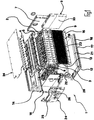
- FIG. 1 Based on an embodiment of the invention illustrated battery module 1 is part of a battery arrangement, not shown in the figures, a plurality of such battery modules 1 having. How the battery modules 1 are assembled for this, for example, results FIG. 6 , which shows two interconnected battery modules 1.
- To the battery module 1 includes a battery unit 2, which is formed by a plurality of interconnected battery cells 3, and a control assembly 4, 5, to which a control board 4 and a support frame 5 belong.
- the battery cells 3 of the battery unit 2 of the battery module 1 are interconnected by means of the best in FIG. 7 illustrated cell connector 6, each cell connector 6 each two battery cells 3 of the battery unit 2 connected to each other.
- FIG. 1 is one of the battery cells 3 in one of the remaining battery cells 3 of the battery unit 2 remote position shown.
- control assembly 4 to which the control board 4 and the support frame 5 are used to monitor and control the operation of the battery unit 2 and is mounted on the battery unit 2.
- the cell connectors 6 are provided, by means of which the correspondingly assigned cell terminals 29 of the battery cells 3 of the battery unit 2 are interconnected.
- the cell terminals 29 of the battery cells 3 protrude into the support frame 5 of the control module 4, 5.
- the battery unit 2 with its in FIG. 3 right end wall in abutment on the inside of a housing end wall 7, which in turn with respect to a housing assembly 12, 13, 14, to which a bottom plate 12 and two side walls 13, 14 belongs, is stationary.
- the battery unit 2 is provided with a clamping member 8.
- the tendon 8 virtually forms the other end wall of the battery unit. 2
- clamping member 8 Between the voltage applied to the housing end wall 7 end wall of the battery unit 2 and the clamping member 8 extending rods 9, which are formed at their the clamping member 8 associated end portions with threaded portions 10.
- the threaded portions 10 penetrate openings provided on the clamping member 8 and carry at their free ends clamping nuts 11.
- the clamping member 8 can be adjusted in the direction of the housing end wall 7 associated end wall of the battery unit 2, whereby the battery cells 3 of the battery unit 2 are pressed against each other.
- an insulating film 33 is provided, by means of which the individual battery cells 3 of the battery unit 2 are electrically isolated from each other. This is true even if the battery cells 3 of the battery unit 2 are pressed firmly against each other by means of the clamping member 8.
- the two side walls 13, 14 have, as from FIG. 1 shows, at its lower longitudinal edges 15 on the battery unit 2 facing the inside each have a longitudinal projection 16 which extends approximately over the entire length of the respective side wall 13, 14.
- These longitudinal projections 16 of the two side walls 13, 14 are assigned to the two longitudinal edges 17 of the bottom plate 12 formed longitudinal recesses 18.
- the two absorbedwandungs mineralon longitudinal projections 16 engage in their associated bottom plate side longitudinal recess 18, resulting in a positive connection between the bottom plate 12 on the one hand and the Both side walls 13, 14 on the other hand results.
- a receiving tray 20 is arranged, which is formed in the illustrated embodiment of plastic.
- the receiving tray 20 rests on the inside of the bottom plate 12 and has at its two longitudinal sides bends 21, 22 which project in the direction of the battery unit 2 and extend over the entire length of the receiving tray 20. Between the two folds 21, 22 of the receiving tray 20, a lower portion of the battery unit 2 and the battery cells 3 is received and halterbar.
- the two side walls 13, 14 of the housing assembly 12, 13, 14 of the battery module 1 are in the case of in FIG. 1 illustrated embodiment of the battery module 1 is formed with a plurality of cooling fins 23 which extend parallel to each other and with a relatively small distance from each other over the length of the side walls 13, 14.
- the side walls 13, 14 of the housing assembly 12, 13, 14 can also be water or air cooled.
- the side wall 13 thereof with an approximately U-shaped projection portion 35 in the illustrated embodiment, which is closed in the illustrated embodiment on the housing end wall 7 facing away from the end of the battery unit 2 open and in the region of the housing end wall 7. Between this U-shaped projection portion 35, a recess portion 36 is provided.
- a projection section 37 is formed, which is designed to be complementary in its shape to the recess section 36 of the first side wall 13.
- the side wall 14 provided with the projecting portion 37 has a recess portion 38 which surrounds the projecting portion 37 and which is shaped to be complementary in shape to the U-shaped projecting portion 35 of the first side wall 13.
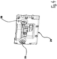
- connection plate 24 On its front side opposite the housing end wall 7, the housing assembly 12, 13, 14 of the battery module 1 is closed by means of a connection plate 24.
- the connection plate 24 is provided with a connection terminal 25 or 26 for each of the two busbars of the battery unit 2.
- the two connection terminals 25, 26 are each formed as a double-nut connection and on their outer sides with a relatively small technical and design effort electrical elements can be connected.
- connection plate 24 On the inside of the connection plate 24 whose connection terminals 25, 26 associated with them terminal ends of the two bus bars of the battery module 1 and der Batterieisme 2 strigbar.
- the cell connectors 6 of the battery module 1 are, as best of the Figures 2 and 7 emerges composed of a contact member 27 and a connecting member 32nd
- the contact member 27 serves to connect each of two battery cells 3 of the battery unit 2 to each other and for this purpose has a first contact portion 28 which is connectable to a cell terminal 29 of a battery cell 3, and a second contact portion 30 which is connectable to a cell terminal 29 of the other battery cell 3 is. Between the first contact portion 28 and the second contact portion 30 of the contact member 27, a compensation portion 31 is formed. By means of this compensation section ud.dgl are due to temperature changes. occurring positional and manufacturing deviations between the fixed and by means of the cell connector 6 to be connected to each other battery cells 3 compensated.
- connection member 32 of the contact member 27 serves the electrical or control technology connection of the cell connector 6 to the control board 4 of the control assembly 4, 5.
- the connection member 32 is attached to the contact member 27 of the cell connector 6.
- status parameters of the battery cells 3 of the battery module 2 of the battery module connected to the relevant contact element 27 are applied to the control circuit board 4 of the control module 4, 5 of the battery module 1 forwarded. Accordingly, due to these forwarded to the control board status parameters unequal states of charge between the two by the relevant contact member 27 of the cell connector 6 connected to each other battery cells 3 of the battery module can be compensated, which is preferably done automatically in the illustrated embodiment.
- the connecting member 32 is designed with a flexibility that is considerably larger compared to that of the contact member 27.
- FIG. 1 shows that the control board 4, 5 of the control module 4 and the support frame 5, 5 of the battery module 1 rests on the top of the battery unit 2.
- a housing cover 34 is arranged, by means of which the housing or the housing assembly 12, 13, 14 of the battery module 1 is lockable at the top thereof.
- the above-described battery modules 1 can be assembled to any number of such battery modules 1 having battery arrangements. It is possible that to a battery assembly, the battery modules 1 are connected to each other, subunits each having a plurality of battery modules 1, which are arranged spatially separated from each other.
Landscapes
- Chemical & Material Sciences (AREA)
- Chemical Kinetics & Catalysis (AREA)
- Electrochemistry (AREA)
- General Chemical & Material Sciences (AREA)
- Engineering & Computer Science (AREA)
- Manufacturing & Machinery (AREA)
- Battery Mounting, Suspending (AREA)
- Secondary Cells (AREA)
Abstract
Ein Batteriemodul für eine Mehrzahl derartiger Batteriemodule (1) aufweisende Batterieanordnungen hat eine Batterieeinheit (2), die eine Vielzahl miteinander verbundener Batteriezellen (3) aufweist, eine Gehäusebaugruppe (12, 13, 14) mit einer Bodenplatte (12) und zwei einander gegenüberliegend angeordneten Seitenwandungen (13, 14), die vorzugsweise mittels Schraubverbindungen (19) mit der Bodenplatte (12) verbindbar sind und an ihren unteren Längskanten (15) auf ihrer Innenseite Längsvorsprünge (16) aufweisen, die in an zugeordneten Längskanten (17) der Bodenplatte (12) ausgebildete Längsausnehmungen (18) eingreifen, und einer Aufnahmeschale (20), die aus Kunststoff ausgebildet ist, auf der Innenseite der Bodenplatte (12) ruht und an ihren Längsseiten in aufwärtiger Richtung vorstehende Abkantungen (21, 22) , aufweist, zwischen denen ein unterer Abschnitt der Batterieeinheit (2) des Batteriemoduls (1) aufnehmbar ist, und eine Steuerbaugruppe (4, 5), die eine Steuerplatine (4) zur Überwachung und Regelung des Betriebs der Batterieeinheit (2) und einen Tragrahmen (5) aufweist, der auf der Batterieeinheit (2) lagert und an dem Zellverbinder angeordnet sind, mittels denen jeweils zwei Batteriezellen (3) der Batterieeinheit (2) untereinander verbindbar sind.A battery module for a plurality of such battery modules (1) having battery arrangements has a battery unit (2) having a plurality of interconnected battery cells (3), a housing assembly (12, 13, 14) with a bottom plate (12) and two arranged opposite one another Side walls (13, 14), which are preferably by means of screw (19) connected to the bottom plate (12) and at its lower longitudinal edges (15) on its inner side longitudinal projections (16) in at associated longitudinal edges (17) of the bottom plate ( 12) formed longitudinal recesses (18) engage, and a receiving shell (20) which is formed of plastic, on the inside of the bottom plate (12) rests and on their longitudinal sides in the upward direction projecting folds (21, 22), between which a lower portion of the battery unit (2) of the battery module (1) is receivable, and a control assembly (4, 5) having a control board ( 4) for monitoring and regulating the operation of the battery unit (2) and a support frame (5) which is mounted on the battery unit (2) and arranged on the cell connector, by means of which two battery cells (3) of the battery unit (2) with each other are connectable.
Description
Die Erfindung bezieht sich auf ein Batteriemodul für eine Mehrzahl derartiger Batteriemodule aufweisende Batterieanordnungen, mit einer Batterieeinheit, die eine Vielzahl miteinander verbundener Batteriezellen aufweist, einer Steuerbaugruppe, die eine Steuerplatine zur Überwachung und Regelung des Betriebs der Batterieeinheit und einen Tragrahmen aufweist, der auf der Batterieeinheit lagert und an dem Zellverbinder angeordnet sind, mittels denen jeweils zwei Batteriezellen der Batterieeinheit untereinander verbindbar sind.The invention relates to a battery module for a plurality of such battery modules having battery assemblies, comprising a battery unit having a plurality of interconnected battery cells, a control assembly having a control board for monitoring and control of the operation of the battery unit and a support frame which on the battery unit stores and are arranged on the cell connector, by means of which in each case two battery cells of the battery unit can be connected to one another.
Derartige Batteriemodule werden, wie vorstehend bereits erwähnt, zu teilweise auch großvolumigen Batterieanordnungen zusammengefügt, um beispielsweise auch Fahrzeuge, wie Busse etc., mit elektrischer Antriebsenergie versorgen zu können. Aufgrund der großen Kapazitäten, die bei derartigen Fahrzeugen angefragt werden, muß eine große Anzahl von miteinander in Verbindung stehenden Batteriezellen und eine ebenfalls vergleichsweise große Anzahl von Batteriemodulen, in denen diese Batteriezellen zusammengefaßt sind, zu einer Batterieanordnung zusammengefaßt werden, die dauerhaft und zuverlässig gewährleistet, dass die für den Betrieb des Fahrzeugs erforderliche Antriebsenergie zur Verfügung gestellt wird.Such battery modules are, as already mentioned above, sometimes joined together also large-volume battery arrangements, for example, to provide vehicles such as buses, etc., with electrical drive energy. Due to the large capacities that are required in such vehicles, a large number of interconnected battery cells and a likewise comparatively large number of battery modules, in which these battery cells are combined, must be combined to form a battery that permanently and reliably ensures that the drive energy required for the operation of the vehicle is provided.
Ausgehend von dem eingangs geschilderten Stand der Technik liegt der Erfindung die Aufgabe zugrunde, ein Batteriemodul für eine Mehrzahl derartiger Batteriemodule aufweisende Batterieanordnungen zur Verfügung zu stellen, welches dauerhaft betriebssicher und weitgehend störungsfrei funktionsfähig ist.Based on the above-described prior art, the present invention seeks to provide a battery module for a plurality of such battery modules having battery arrangements available, which is permanently reliable and largely trouble-free functioning.
Diese Aufgabe wird erfindungsgemäß dadurch gelöst, dass die Batterieeinheit des Batteriemoduls mit einer Stirnwand an einer in Bezug auf ein Gehäuse des Batteriemoduls ortsfest angeordneten Gehäusestirnwand anliegt und dass an der der ortsfesten Gehäusestirnwand entfernten Stirnwand der Batterieeinheit ein Spannglied angeordnet ist, welches in Längsrichtung der Batterieeinheit auf die ortsfeste Gehäusestirnwand zu verstellbar ist. Mittels des Spannglieds lässt sich eine gegen jedwede mechanische Beanspruchungen dauerhaft aufrechterhaltbare räumliche Fixierung der Batterieeinheiten des Batteriemoduls aneinander und in Bezug auf das Gehäuse des Batteriemoduls sicherstellen.This object is achieved in that the battery unit of the battery module rests with an end wall on a stationary with respect to a housing of the battery module arranged housing end wall and that on the stationary housing end wall remote end wall of the battery unit, a clamping member is arranged, which in the longitudinal direction of the battery unit the stationary housing end wall is adjustable. By means of the tendon can be a permanently upheld against any mechanical stresses spatial fixation of the battery units of the battery module to each other and with respect to the housing of the battery module to ensure.
In technisch-konstruktiv vergleichsweise wenig aufwendiger Weise lässt sich diese räumliche Fixierung bewerkstelligen, wenn zwischen der ortsfesten Gehäusestirnwand des Batteriemoduls und dessen Spannglied Stäbe angeordnet sind, die spanngliedseitig Gewindeabschnitte mit Spannmuttern aufweisen, mittels denen das Spannglied in Richtung zur ortsfesten Gehäusestirnwand verstellbar ist. Durch Drehen der Spannmuttern, die zwecks Ausgleich von Fertigungstoleranzen od.dgl. auch in unterschiedlicher Weise gedreht werden können, kann die räumliche Fixierung zwischen den Batteriezellen der Batterieeinheit des Batteriemoduls wirksam hergestellt werden.In a technically-structurally comparatively inexpensive manner, this spatial fixation can be achieved if rods are arranged between the fixed housing end wall of the battery module and its tension member, the tension member side threaded portions having clamping nuts, by means of which the clamping member is adjustable in the direction of the stationary housing end wall. By turning the clamping nuts or the like to compensate for manufacturing tolerances. can also be rotated in different ways the spatial fixation between the battery cells of the battery unit of the battery module are made effective.
Wenn das Batteriemodul eine Gehäusebaugruppe mit einer Bodenplatte und zwei einander gegenüberliegend angeordneten Seitenwandungen aufweist, die an ihren unteren Längskanten auf ihrer Innenseite Längsvorsprünge aufweisen, die in an zugeordneten Längskanten der Bodenplatte ausgebildete Längsausnehmungen eingreifen und vorzugsweise mittels Schraubverbindungen mit der Bodenplatte verbindbar sind, wobei darüber hinaus eine Aufnahmeschale vorgesehen ist, die aus Kunststoff ausgebildet ist, auf der Innenseite der Bodenplatte ruht und an ihren Längsseiten in aufwärtiger Richtung vorstehende Abkantungen aufweist, zwischen denen ein unterer Abschnitt der Batterieeinheit des Batteriemoduls aufnehmbar ist, lässt sich die Batterieeinheit in einfacher Weise innerhalb des Gehäuses bzw. der Gehäusebaugruppe aufnehmen, wobei einerseits eine gewisse Flexibilität des Batteriemoduls erreichbar ist und andererseits dennoch eine feste räumliche Fixierung der Batterieeinheit innerhalb des Gehäuses des Batteriemoduls gesichert wird.When the battery module comprises a housing assembly having a bottom plate and two oppositely disposed side walls having at their lower longitudinal edges on its inner side longitudinal projections which engage in formed on associated longitudinal edges of the bottom plate longitudinal recesses and are preferably connectable by means of screw with the bottom plate, wherein moreover a receiving tray is provided which is formed of plastic, rests on the inside of the bottom plate and having on their longitudinal sides in the upward direction projecting folds, between which a lower portion of the battery unit of the battery module is receivable, the battery unit can be easily within the housing or the housing assembly record, on the one hand a certain flexibility of the battery module is reached and on the other hand still a fixed spatial fixation of the battery unit within the Geh äuses the battery module is secured.
Zur Verbesserung der Wärmeabfuhr aus der Batterieeinheit kann es zweckmäßig sein, auf der Außenfläche der Seitenwandungen der Gehäusebaugruppe des Batteriemoduls eine Vielzahl Kühlrippen auszugestalten.To improve the heat dissipation from the battery unit, it may be expedient to design a plurality of cooling fins on the outer surface of the side walls of the housing module of the battery module.
Alternativ oder kumulativ können die genannten Seitenwandungen der Gehäusebaugruppe auch wassergekühlt oder luftgekühlt ausgestaltet werden.Alternatively or cumulatively, the said side walls of the housing assembly can also be made water-cooled or air-cooled.
Um eine mehrere derartige Batteriemodule aufweisende Batterieanordnung kompakt und mechanisch stabil auszugestalten, ist es vorteilhaft, wenn jede an einer Seitenwandung eines benachbarten Batteriemoduls angeordnete Seitenwandung eine räumliche Struktur mit zumindest einem Vorsprungabschnitt und zumindest einem Ausnehmungsabschnitt aufweist, der in den zumindest einen Ausnehmungsabschnitt der zugeordneten Seitenwandung des benachbarten Batteriemoduls eingreift bzw. in den der zumindest eine Vorsprungabschnitt der zugeordneten Seitenwandung des benachbarten Batteriemoduls eingreift.In order to make a battery arrangement having a plurality of such battery modules compact and mechanically stable, it is advantageous if each side wall of an adjacent battery module arranged side wall has a spatial structure with at least one projection portion and at least one recess portion in the at least one recess portion of the associated side wall of the adjacent battery module engages or in which engages the at least one projection portion of the associated side wall of the adjacent battery module.
Eine weitere Erhöhung der Kompaktheit und der mechanischen Stabilität ist erreichbar, wenn die räumliche Struktur der Seitenwandungen zu der der Seitenwandungen benachbarter Batteriemodule komplementär gestaltet ist.A further increase in compactness and mechanical stability is achievable if the spatial structure of the sidewalls is made complementary to that of the sidewalls of adjacent battery modules.
Um mehrere derartige Batteriemodule in einfacher Weise und mit einem geringen Aufwand aneinander anschließbar zu gestalten, ist es vorteilhaft, wenn zu dem Batteriemodul eine Anschlussplatte gehört, mittels der eine Gehäusebaugruppe des Batteriemoduls an einer Stirnseite der- bzw. desselben verschließbar ist und die für jede der beiden Stromschienen des Batteriemoduls einen Anschlussterminal aufweist, wobei jedes Anschlussterminal als Doppelmutterverbindung ausgebildet und an seiner Außenseite anschließbar ist.In order to make a plurality of such battery modules in a simple manner and with little effort connected to each other, it is advantageous if the battery module includes a connection plate by means of a housing assembly of the battery module at one end of the same or is closed and the for each of two busbars of the battery module has a connection terminal, wherein each connection terminal is formed as a double-nut connection and connectable to its outside.
Zweckmäßigerweise ist die Anschlussplatte an ihren Anschlußterminals mit Anschlussenden der Stromschienen des jeweiligen Batteriemoduls verschraubbar.Conveniently, the connection plate is screwed to their connection terminals with connection ends of the busbars of the respective battery module.
Mit einem vergleichsweise geringen technisch-konstruktiven Aufwand und mit hoher Zuverlässigkeit lassen sich die Batteriezellen einer Batterieeinheit miteinander verbinden, wenn jeder Zellverbinder des Batteriemoduls ein Kontaktglied, das dem Anschluss zweier Batteriezellen aneinander dient und hierzu einen ersten Kontaktabschnitt, der mit einem Zellterminal der einen Batteriezelle verbindbar ist, einen zweiten Kontaktabschnitt, der mit einem Zellterminal der anderen Batteriezelle verbindbar ist, und einen Ausgleichsabschnitt, der zwischen dem ersten und dem zweiten Kontaktabschnitt angeordnet ist und mittels dem z.B. aufgrund von Temperaturänderungen ud.dgl. auftretende Positions- und Fertigungsabweichungen zwischen den fixierten und mittels des Zellverbinders aneinander anzuschließenden Batteriezellen ausgleichbar sind aufweist, und ein Anschlussglied hat, mittels dem der Zellverbinder an die Steuerplatine der Steuerbaugruppe des Batteriemoduls anschließbar ist, das am Kontaktglied des Zellverbinders angebracht ist, mittels dem Statusparameter der Batteriezellen an die Steuerplatine der Steuerbaugruppe des Batteriemoduls weiterleitbar sind, mittels dem im Zusammenwirken mit der Steuerplatine ungleiche Ladezustände zwischen den beiden durch das Kontaktglied des Zellverbinders aneinander angeschlossenen Batteriezellen des Batteriemoduls vorzugsweise automatisch ausgleichbar sind, und dessen Flexibilität im Vergleich zu der des Kontaktglieds erheblich größer ist.With a comparatively low technical and design effort and with high reliability, the battery cells can be connect a battery unit, when each cell connector of the battery module, a contact member, the connection of two battery cells together and for this purpose a first contact portion which is connectable to a cell terminal of the one battery cell, a second contact portion which is connectable to a cell terminal of the other battery cell, and a balancing section, which is arranged between the first and the second contact portion and by means of, for example, due to temperature changes ud.dgl. having positional and manufacturing deviations compensated between the fixed and to be connected by the cell connector to each other battery cells, and a connection member has, by means of which the cell connector is connectable to the control board of the control module of the battery module, which is attached to the contact member of the cell connector, by means of the status parameter of Battery cells are forwarded to the control board of the control module of the battery module, by means of which in cooperation with the control board unequal charge states between the two by the contact member of the cell connector connected battery cells of the battery module are preferably automatically compensated, and its flexibility is considerably greater compared to that of the contact member ,
Vorzugsweise ist in der Steuerplatine des Batteriemoduls die Temperatur jeder Batteriezelle überwachbar.Preferably, the temperature of each battery cell can be monitored in the control board of the battery module.
Um Kurzschlüsse innerhalb eines Batteriemoduls zu verhindern, ist es zweckmäßig, wenn zwischen den Batteriezellen der Batterieeinheit eine Isolierfolie angeordnet ist, mittels der die einzelnen Batteriezellen der Batterieeinheit voneinander elektrisch isolierbar sind.In order to prevent short circuits within a battery module, it is expedient if an insulating film is arranged between the battery cells of the battery unit, by means of which the individual battery cells of the battery unit are electrically isolated from each other.
Zwischen der Oberseite der Batterieeinheit und einem Gehäusedeckel ist vorteilhaft die Steuerbaugruppe mit ihrer Steuerplatine und ihrem Tragrahmen angeordnet.Between the top of the battery unit and a housing cover, the control module is advantageously arranged with its control board and its support frame.
Je nach den räumlichen Verhältnissen, in denen eine mehrere Batteriemodule aufweisende Batterieanordnung zu installieren ist, kann es zweckmäßig sein, wenn die einzelnen Batteriemodule der Batterieanordnung in voneinander räumlich getrennten Teileinheiten angeordnet werden.Depending on the spatial conditions in which a battery arrangement having a plurality of battery modules is to be installed, it may be expedient for the individual battery modules of the battery arrangement to be arranged in spatially separated partial units.
Im Folgenden wird die Erfindung anhand von Ausführungsformen unter Bezugnahme auf die Zeichnungen näher erläutert. Es zeigen:
Figur 1- eine perspektivische Explosionsdarstellung eines Ausführungsbeispiels eines erfindungsgemäßen Batteriemoduls, das zu einer mehrere derartiger Batteriemodule aufweisenden Batterieanordnung zusammenstellbar ist;
- Figur 2
- eine perspektivische Darstellung einer Steuerbaugruppe des in
Figur 1 Figur 3- eine perspektivische Darstellung einer Batterieeinheit der in
Figur 1 - Figur 4
- eine perspektivische Darstellung einer Anschlußplatte des in
Figur 1 Figur 5- eine perspektivische Darstellung zweier erfindungsgemäßer Batteriemodule in einer abgewandelten Ausführungsform;
Figur 6- eine perspektivische Darstellung der beiden in
Figur 5 Figur 7- eine perspektivische Prinzipdarstellung eines Zellverbinders für das erfindungsgemäße Batteriemodul.
- FIG. 1
- an exploded perspective view of an embodiment of a battery module according to the invention, which is assembled to a plurality of such battery modules having battery assembly;
- FIG. 2
- a perspective view of a control assembly of in
FIG. 1 shown embodiment of the battery module according to the invention; - FIG. 3
- a perspective view of a battery unit of in
FIG. 1 shown embodiment of the battery module according to the invention; - FIG. 4
- a perspective view of a connection plate of in
FIG. 1 shown embodiment of the battery module according to the invention; - FIG. 5
- a perspective view of two battery modules according to the invention in a modified embodiment;
- FIG. 6
- a perspective view of the two in
FIG. 5 shown battery modules in the assembled state; and - FIG. 7
- a perspective schematic diagram of a cell connector for the battery module according to the invention.
Ein in
Zu dem Batteriemodul 1 gehören eine Batterieeinheit 2, die durch eine Vielzahl miteinander verbundener Batteriezellen 3 gebildet wird, und eine Steuerbaugruppe 4, 5, zu der eine Steuerplatine 4 und ein Tragrahmen 5 gehören.To the
Die Batteriezellen 3 der Batterieeinheit 2 des Batteriemoduls 1 sind untereinander mittels am besten in
Die in
Wie sich am besten aus
Zwischen der an der Gehäusestirnwand 7 anliegenden Stirnwand der Batterieeinheit 2 und dem Spannglied 8 erstrecken sich Stäbe 9, die an ihren dem Spannglied 8 zugeordneten Endabschnitten mit Gewindeabschnitten 10 ausgebildet sind. Die Gewindeabschnitte 10 durchdringen am Spannglied 8 vorgesehene Öffnungen und tragen an ihren freien Enden Spannmuttern 11. Durch entsprechende Drehung der Spannmuttern 11 kann das Spannglied 8 in Richtung auf die der Gehäusestirnwand 7 zugeordnete Stirnwand der Batterieeinheit 2 verstellt werden, wodurch die Batteriezellen 3 der Batterieeinheit 2 aneinander- gedrückt werden.Between the voltage applied to the
Zwischen den einzelnen Batteriezellen 3 der Batterieeinheit 2 ist jeweils eine Isolierfolie 33 vorgesehen, mittels der die einzelnen Batteriezellen 3 der Batterieeinheit 2 voneinander elektrisch isoliert sind. Dies gilt auch dann, wenn die Batteriezellen 3 der Batterieeinheit 2 mittels des Spannglieds 8 fest gegeneinander verpresst werden.Between the
Zu dem Batteriemodul 1, wie es in
Zwischen der der Batterieeinheit 2 bzw. den Batteriezellen 3 derselben zugewandten Oberseite der Bodenplatte 12 und der Unterseite der Batterieeinheit 2 bzw. der Batteriezellen 3 ist eine Aufnahmeschale 20 angeordnet, die im Falle der dargestellten Ausführungsform aus Kunststoff ausgebildet ist. Die Aufnahmeschale 20 ruht auf der Innenseite der Bodenplatte 12 und hat an ihren beiden Längsseiten Abkantungen 21, 22, die in Richtung zur Batterieeinheit 2 vorstehen und sich über die gesamte Länge der Aufnahmeschale 20 erstrecken. Zwischen den beiden Abkantungen 21, 22 der Aufnahmeschale 20 ist ein unterer Abschnitt der Batterieeinheit 2 bzw. der Batteriezellen 3 aufnehm- und halterbar.Between the battery unit 2 and the
Die beiden Seitenwandungen 13, 14 der Gehäusebaugruppe 12, 13, 14 des Batteriemoduls 1 sind im Falle des in
Alternativ oder kumulativ können die Seitenwandungen 13, 14 der Gehäusebaugruppe 12, 13, 14 auch wasser- oder luftgekühlt werden.Alternatively or cumulatively, the
Bei einer anhand der
Auf der anderen Seitenwandung 14 der Gehäusebaugruppe 12, 13, 14 ist, wie sich am besten aus der Darstellung des in
Wenn zwei Batteriemodule 1, wie dies in
An ihrer der Gehäusestirnwand 7 entgegengesetzten Stirnseite ist die Gehäusebaugruppe 12, 13, 14 des Batteriemoduls 1 mittels einer Anschlussplatte 24 geschlossen. Die Anschlussplatte 24 ist für jede der beiden Stromschienen der Batterieeinheit 2 mit einem Anschlussterminal 25 bzw. 26 versehen. Die beiden Anschlußterminale 25, 26 sind jeweils als Doppelmutterverbindung ausgebildet und an ihren Außenseiten mit einem vergleichsweise geringen technisch-konstruktiven Aufwand an elektrische Elemente anschließbar. Auf der Innenseite der Anschlussplatte 24 sind deren Anschlussterminals 25, 26 mit ihnen zugeordneten Anschlussenden der beiden Stromschienen des Batteriemoduls 1 bzw. der Batterieeinheit 2 verschraubbar.On its front side opposite the
Die Zellverbinder 6 des Batteriemoduls 1 sind, wie am besten aus den
Das Kontaktglied 27 dient dem Anschluß jeweils zweier Batteriezellen 3 der Batterieeinheit 2 aneinander und hat hierzu einen ersten Kontaktabschnitt 28, der mit einem Zellterminal 29 der einen Batteriezelle 3 verbindbar ist, und einen zweiten Kontaktabschnitt 30, der mit einem Zellterminal 29 der anderen Batteriezelle 3 verbindbar ist. Zwischen dem ersten Kontaktabschnitt 28 und dem zweiten Kontaktabschnitt 30 des Kontaktglieds 27 ist ein Ausgleichabschnitt 31 ausgebildet. Mittels dieses Ausgleichsabschnitts sind aufgrund von Temperaturänderungen ud.dgl. auftretende Positions- und Fertigungsabweichungen zwischen den fixierten und mittels des Zellverbinders 6 aneinander anzuschließenden Batteriezellen 3 ausgleichbar.The
Das Anschlussglied 32 des Kontaktglieds 27 dient dem elektrischen bzw. steuerungstechnischen Anschluß des Zellverbinders 6 an die Steuerplatine 4 der Steuerbaugruppe 4, 5. Das Anschlussglied 32 ist am Kontaktglied 27 des Zellverbinders 6 angebracht. Mittels dem Anschlussglied 32 sind Statusparameter der an das betreffende Kontaktglied 27 angeschlossenen Batteriezellen 3 der Batterieeinheit 2 des Batteriemoduls an die Steuerplatine 4 der Steuerbaugruppe 4, 5 des Batteriemoduls 1 weiterleitbar. Entsprechend können aufgrund dieser an die Steuerplatine weitergeleiteter Statusparameter ungleiche Ladezustände zwischen den beiden durch das betreffende Kontaktglied 27 des Zellverbinders 6 aneinander angeschlossenen Batteriezellen 3 des Batteriemoduls ausgeglichen werden, wobei dies in der dargestellten Ausführungsform vorzugsweise automatisch erfolgt. Das Anschlussglied 32 ist mit einer Flexibilität ausgestaltet, die im Vergleich zu der des Kontaktglieds 27 erheblich größer ist.The
Dadurch, dass jeder Zellverbinder 6 der Batterieeinheit 2 mit einem Anschlussglied 32 ausgerüstet und so an die Steuerplatine 4 der Steuerbaugruppe 4, 5 des Batteriemoduls 1 angeschlossen ist, kann die Temperatur jeder einzelnen Batteriezelle 3 der Batterieeinheit 2 überwacht werden.Characterized in that each
Aus
Wie dies in
Claims (15)
Priority Applications (2)
| Application Number | Priority Date | Filing Date | Title |
|---|---|---|---|
| PL17000464T PL3214670T3 (en) | 2015-05-13 | 2016-04-15 | Battery module for battery devices comprising a number of such battery modules |
| HRP20200316TT HRP20200316T1 (en) | 2015-05-13 | 2020-02-25 | Battery module for battery devices comprising a number of such battery modules |
Applications Claiming Priority (2)
| Application Number | Priority Date | Filing Date | Title |
|---|---|---|---|
| DE102015006168.2A DE102015006168A1 (en) | 2015-05-13 | 2015-05-13 | Battery module for a plurality of such battery modules having battery assemblies |
| EP16000856.1A EP3093901B1 (en) | 2015-05-13 | 2016-04-15 | Battery module for battery devices comprising a number of such battery modules |
Related Parent Applications (2)
| Application Number | Title | Priority Date | Filing Date |
|---|---|---|---|
| EP16000856.1A Division EP3093901B1 (en) | 2015-05-13 | 2016-04-15 | Battery module for battery devices comprising a number of such battery modules |
| EP16000856.1A Division-Into EP3093901B1 (en) | 2015-05-13 | 2016-04-15 | Battery module for battery devices comprising a number of such battery modules |
Publications (3)
| Publication Number | Publication Date |
|---|---|
| EP3214670A2 true EP3214670A2 (en) | 2017-09-06 |
| EP3214670A3 EP3214670A3 (en) | 2017-11-22 |
| EP3214670B1 EP3214670B1 (en) | 2019-12-04 |
Family
ID=55759438
Family Applications (2)
| Application Number | Title | Priority Date | Filing Date |
|---|---|---|---|
| EP17000464.2A Active EP3214670B1 (en) | 2015-05-13 | 2016-04-15 | Battery module for battery devices comprising a number of such battery modules |
| EP16000856.1A Active EP3093901B1 (en) | 2015-05-13 | 2016-04-15 | Battery module for battery devices comprising a number of such battery modules |
Family Applications After (1)
| Application Number | Title | Priority Date | Filing Date |
|---|---|---|---|
| EP16000856.1A Active EP3093901B1 (en) | 2015-05-13 | 2016-04-15 | Battery module for battery devices comprising a number of such battery modules |
Country Status (4)
| Country | Link |
|---|---|
| EP (2) | EP3214670B1 (en) |
| DE (1) | DE102015006168A1 (en) |
| HR (2) | HRP20200132T1 (en) |
| PL (2) | PL3093901T3 (en) |
Cited By (1)
| Publication number | Priority date | Publication date | Assignee | Title |
|---|---|---|---|---|
| CN112310525A (en) * | 2019-08-14 | 2021-02-02 | 宁德时代新能源科技股份有限公司 | Battery box |
Families Citing this family (5)
| Publication number | Priority date | Publication date | Assignee | Title |
|---|---|---|---|---|
| DE102017130556B4 (en) * | 2017-12-19 | 2019-08-08 | Webasto SE | battery assembly |
| DE102018002334B3 (en) * | 2018-03-21 | 2019-07-18 | Voltabox Ag | Battery cell unit for battery modules |
| CN111599957A (en) * | 2020-04-27 | 2020-08-28 | 威睿电动汽车技术(宁波)有限公司 | Battery module and battery pack |
| DE102020005872A1 (en) * | 2020-09-25 | 2022-03-31 | Voltabox Ag | Electric battery for an electrically or partially electrically driven motor vehicle, mobile or stationary unit |
| CN113675522B (en) * | 2021-08-19 | 2023-07-28 | 福建云众动力科技有限公司 | Lithium battery suitable for underwater equipment |
Family Cites Families (8)
| Publication number | Priority date | Publication date | Assignee | Title |
|---|---|---|---|---|
| KR20110118807A (en) * | 2010-01-29 | 2011-11-01 | 파나소닉 주식회사 | Cell module |
| DE102011075044A1 (en) * | 2011-05-02 | 2012-11-08 | Schaeffler Technologies AG & Co. KG | battery case |
| JP2013025983A (en) * | 2011-07-20 | 2013-02-04 | Sanyo Electric Co Ltd | Power-supply unit, and vehicle equipped with the same |
| WO2013102268A1 (en) * | 2012-01-05 | 2013-07-11 | Electrovaya Inc. | Fluid-cooled battery module containing battery cells |
| JP2014035970A (en) * | 2012-08-10 | 2014-02-24 | Honda Motor Co Ltd | Power storage device |
| DE102013204180B4 (en) * | 2013-03-12 | 2021-07-08 | Robert Bosch Gmbh | Housing for accommodating a cell pack, battery, method for manufacturing a battery and method for manufacturing a fiber-reinforced plastic component for housing a battery |
| DE102013213540A1 (en) * | 2013-07-10 | 2015-01-15 | Robert Bosch Gmbh | Battery with a cell connector, motor vehicle with the battery and method for producing the battery |
| CN204315644U (en) * | 2014-12-05 | 2015-05-06 | 天津市华恒天成科技有限公司 | A kind of splicing construction accumulator box |
-
2015
- 2015-05-13 DE DE102015006168.2A patent/DE102015006168A1/en not_active Withdrawn
-
2016
- 2016-04-15 PL PL16000856T patent/PL3093901T3/en unknown
- 2016-04-15 PL PL17000464T patent/PL3214670T3/en unknown
- 2016-04-15 EP EP17000464.2A patent/EP3214670B1/en active Active
- 2016-04-15 EP EP16000856.1A patent/EP3093901B1/en active Active
-
2020
- 2020-01-28 HR HRP20200132TT patent/HRP20200132T1/en unknown
- 2020-02-25 HR HRP20200316TT patent/HRP20200316T1/en unknown
Non-Patent Citations (1)
| Title |
|---|
| None |
Cited By (2)
| Publication number | Priority date | Publication date | Assignee | Title |
|---|---|---|---|---|
| CN112310525A (en) * | 2019-08-14 | 2021-02-02 | 宁德时代新能源科技股份有限公司 | Battery box |
| US11909059B2 (en) | 2019-08-14 | 2024-02-20 | Contemporary Amperex Technology Co., Limited | Battery box |
Also Published As
| Publication number | Publication date |
|---|---|
| EP3214670A3 (en) | 2017-11-22 |
| EP3214670B1 (en) | 2019-12-04 |
| HRP20200132T1 (en) | 2020-05-15 |
| EP3093901A3 (en) | 2016-12-14 |
| PL3214670T3 (en) | 2020-06-01 |
| DE102015006168A1 (en) | 2016-11-17 |
| HRP20200316T1 (en) | 2020-06-12 |
| EP3093901B1 (en) | 2019-11-06 |
| EP3093901A2 (en) | 2016-11-16 |
| PL3093901T3 (en) | 2020-05-18 |
Similar Documents
| Publication | Publication Date | Title |
|---|---|---|
| EP3214670B1 (en) | Battery module for battery devices comprising a number of such battery modules | |
| DE102004031707B4 (en) | Intelligent junction box for motor vehicles | |
| DE102009023607B4 (en) | Distributor for electrical power with current sensor | |
| DE102011076324B4 (en) | Power electronic system with connection means of first and second subsystems | |
| DE112013006395T5 (en) | BDU | |
| DE102006032258A1 (en) | Electrical connector box for motor vehicles | |
| DE102015207127A1 (en) | Locking structure between an element to be stored and a storage body | |
| DE102010060070B4 (en) | Electrical distribution box | |
| DE102011081307B4 (en) | Electrical distribution box | |
| DE112019000420T5 (en) | Electric compressor | |
| DE112014005950T5 (en) | Electronic device with cooling function | |
| EP3015030A1 (en) | Device for supplying electric power to power consumers arranged on a shelf | |
| EP2270821B1 (en) | Wind energy system with a converter and at least one high performance resistor | |
| DE102012202059A1 (en) | fuse assembly | |
| DE112019000423T5 (en) | Electric compressor | |
| DE102017127895A1 (en) | Inverter for electric motor | |
| DE19724254A1 (en) | Central electrical arrangement esp for motor vehicle | |
| WO2018108498A1 (en) | Decoupling element for connecting power electronics to an electric machine | |
| DE102008064499B4 (en) | Variable connection device for an electrical machine | |
| DE202010008274U1 (en) | Electrical connection between two busbars of planar conductors and an insulating layer arranged between the conductors | |
| DE102012201753A1 (en) | Capacitor used in power electronic circuit of hybrid vehicle, has case that is arranged for fastening capacitor between coils, such that longitudinal extension axis of case and winding axis of coils are aligned parallel to each other | |
| DE102020212249B4 (en) | Control cabinet with a cable laying box | |
| DE102018109601B4 (en) | Control cabinet arrangement with protective conductor function | |
| DE102013020788A1 (en) | Cell block for a battery | |
| DE19713948A1 (en) | Inner construction system for switching cabinets |
Legal Events
| Date | Code | Title | Description |
|---|---|---|---|
| PUAI | Public reference made under article 153(3) epc to a published international application that has entered the european phase |
Free format text: ORIGINAL CODE: 0009012 |
|
| STAA | Information on the status of an ep patent application or granted ep patent |
Free format text: STATUS: THE APPLICATION HAS BEEN PUBLISHED |
|
| AC | Divisional application: reference to earlier application |
Ref document number: 3093901 Country of ref document: EP Kind code of ref document: P |
|
| AK | Designated contracting states |
Kind code of ref document: A2 Designated state(s): AL AT BE BG CH CY CZ DE DK EE ES FI FR GB GR HR HU IE IS IT LI LT LU LV MC MK MT NL NO PL PT RO RS SE SI SK SM TR |
|
| AX | Request for extension of the european patent |
Extension state: BA ME |
|
| PUAL | Search report despatched |
Free format text: ORIGINAL CODE: 0009013 |
|
| AK | Designated contracting states |
Kind code of ref document: A3 Designated state(s): AL AT BE BG CH CY CZ DE DK EE ES FI FR GB GR HR HU IE IS IT LI LT LU LV MC MK MT NL NO PL PT RO RS SE SI SK SM TR |
|
| AX | Request for extension of the european patent |
Extension state: BA ME |
|
| RIC1 | Information provided on ipc code assigned before grant |
Ipc: H01M 2/20 20060101ALI20171017BHEP Ipc: H01M 10/613 20140101ALI20171017BHEP Ipc: H01M 10/625 20140101ALI20171017BHEP Ipc: H01M 10/42 20060101ALN20171017BHEP Ipc: H01M 2/10 20060101AFI20171017BHEP Ipc: H01M 10/6554 20140101ALI20171017BHEP Ipc: H01M 10/647 20140101ALI20171017BHEP |
|
| STAA | Information on the status of an ep patent application or granted ep patent |
Free format text: STATUS: REQUEST FOR EXAMINATION WAS MADE |
|
| 17P | Request for examination filed |
Effective date: 20180424 |
|
| RBV | Designated contracting states (corrected) |
Designated state(s): AL AT BE BG CH CY CZ DE DK EE ES FI FR GB GR HR HU IE IS IT LI LT LU LV MC MK MT NL NO PL PT RO RS SE SI SK SM TR |
|
| STAA | Information on the status of an ep patent application or granted ep patent |
Free format text: STATUS: EXAMINATION IS IN PROGRESS |
|
| 17Q | First examination report despatched |
Effective date: 20180724 |
|
| GRAP | Despatch of communication of intention to grant a patent |
Free format text: ORIGINAL CODE: EPIDOSNIGR1 |
|
| STAA | Information on the status of an ep patent application or granted ep patent |
Free format text: STATUS: GRANT OF PATENT IS INTENDED |
|
| RIC1 | Information provided on ipc code assigned before grant |
Ipc: H01M 10/6554 20140101ALI20190529BHEP Ipc: H01M 2/20 20060101ALI20190529BHEP Ipc: H01M 10/613 20140101ALI20190529BHEP Ipc: H01M 10/625 20140101ALI20190529BHEP Ipc: H01M 10/647 20140101ALI20190529BHEP Ipc: H01M 2/10 20060101AFI20190529BHEP Ipc: H01M 10/42 20060101ALN20190529BHEP |
|
| RIC1 | Information provided on ipc code assigned before grant |
Ipc: H01M 10/6554 20140101ALI20190604BHEP Ipc: H01M 10/42 20060101ALN20190604BHEP Ipc: H01M 2/20 20060101ALI20190604BHEP Ipc: H01M 10/647 20140101ALN20190604BHEP Ipc: H01M 2/10 20060101AFI20190604BHEP Ipc: H01M 10/613 20140101ALI20190604BHEP Ipc: H01M 10/625 20140101ALN20190604BHEP |
|
| INTG | Intention to grant announced |
Effective date: 20190619 |
|
| GRAS | Grant fee paid |
Free format text: ORIGINAL CODE: EPIDOSNIGR3 |
|
| GRAA | (expected) grant |
Free format text: ORIGINAL CODE: 0009210 |
|
| STAA | Information on the status of an ep patent application or granted ep patent |
Free format text: STATUS: THE PATENT HAS BEEN GRANTED |
|
| AC | Divisional application: reference to earlier application |
Ref document number: 3093901 Country of ref document: EP Kind code of ref document: P |
|
| AK | Designated contracting states |
Kind code of ref document: B1 Designated state(s): AL AT BE BG CH CY CZ DE DK EE ES FI FR GB GR HR HU IE IS IT LI LT LU LV MC MK MT NL NO PL PT RO RS SE SI SK SM TR |
|
| REG | Reference to a national code |
Ref country code: GB Ref legal event code: FG4D Free format text: NOT ENGLISH |
|
| REG | Reference to a national code |
Ref country code: CH Ref legal event code: EP |
|
| REG | Reference to a national code |
Ref country code: AT Ref legal event code: REF Ref document number: 1210527 Country of ref document: AT Kind code of ref document: T Effective date: 20191215 |
|
| REG | Reference to a national code |
Ref country code: DE Ref legal event code: R096 Ref document number: 502016007932 Country of ref document: DE |
|
| REG | Reference to a national code |
Ref country code: IE Ref legal event code: FG4D Free format text: LANGUAGE OF EP DOCUMENT: GERMAN |
|
| REG | Reference to a national code |
Ref country code: HR Ref legal event code: TUEP Ref document number: P20200316 Country of ref document: HR |
|
| REG | Reference to a national code |
Ref country code: SE Ref legal event code: TRGR |
|
| REG | Reference to a national code |
Ref country code: NL Ref legal event code: MP Effective date: 20191204 |
|
| REG | Reference to a national code |
Ref country code: LT Ref legal event code: MG4D |
|
| PG25 | Lapsed in a contracting state [announced via postgrant information from national office to epo] |
Ref country code: GR Free format text: LAPSE BECAUSE OF FAILURE TO SUBMIT A TRANSLATION OF THE DESCRIPTION OR TO PAY THE FEE WITHIN THE PRESCRIBED TIME-LIMIT Effective date: 20200305 Ref country code: NO Free format text: LAPSE BECAUSE OF FAILURE TO SUBMIT A TRANSLATION OF THE DESCRIPTION OR TO PAY THE FEE WITHIN THE PRESCRIBED TIME-LIMIT Effective date: 20200304 Ref country code: BG Free format text: LAPSE BECAUSE OF FAILURE TO SUBMIT A TRANSLATION OF THE DESCRIPTION OR TO PAY THE FEE WITHIN THE PRESCRIBED TIME-LIMIT Effective date: 20200304 Ref country code: LT Free format text: LAPSE BECAUSE OF FAILURE TO SUBMIT A TRANSLATION OF THE DESCRIPTION OR TO PAY THE FEE WITHIN THE PRESCRIBED TIME-LIMIT Effective date: 20191204 Ref country code: FI Free format text: LAPSE BECAUSE OF FAILURE TO SUBMIT A TRANSLATION OF THE DESCRIPTION OR TO PAY THE FEE WITHIN THE PRESCRIBED TIME-LIMIT Effective date: 20191204 Ref country code: LV Free format text: LAPSE BECAUSE OF FAILURE TO SUBMIT A TRANSLATION OF THE DESCRIPTION OR TO PAY THE FEE WITHIN THE PRESCRIBED TIME-LIMIT Effective date: 20191204 |
|
| PG25 | Lapsed in a contracting state [announced via postgrant information from national office to epo] |
Ref country code: RS Free format text: LAPSE BECAUSE OF FAILURE TO SUBMIT A TRANSLATION OF THE DESCRIPTION OR TO PAY THE FEE WITHIN THE PRESCRIBED TIME-LIMIT Effective date: 20191204 |
|
| REG | Reference to a national code |
Ref country code: HR Ref legal event code: ODRP Ref document number: P20200316 Country of ref document: HR Payment date: 20200406 Year of fee payment: 5 |
|
| REG | Reference to a national code |
Ref country code: HR Ref legal event code: T1PR Ref document number: P20200316 Country of ref document: HR |
|
| PG25 | Lapsed in a contracting state [announced via postgrant information from national office to epo] |
Ref country code: AL Free format text: LAPSE BECAUSE OF FAILURE TO SUBMIT A TRANSLATION OF THE DESCRIPTION OR TO PAY THE FEE WITHIN THE PRESCRIBED TIME-LIMIT Effective date: 20191204 |
|
| PG25 | Lapsed in a contracting state [announced via postgrant information from national office to epo] |
Ref country code: ES Free format text: LAPSE BECAUSE OF FAILURE TO SUBMIT A TRANSLATION OF THE DESCRIPTION OR TO PAY THE FEE WITHIN THE PRESCRIBED TIME-LIMIT Effective date: 20191204 Ref country code: NL Free format text: LAPSE BECAUSE OF FAILURE TO SUBMIT A TRANSLATION OF THE DESCRIPTION OR TO PAY THE FEE WITHIN THE PRESCRIBED TIME-LIMIT Effective date: 20191204 Ref country code: CZ Free format text: LAPSE BECAUSE OF FAILURE TO SUBMIT A TRANSLATION OF THE DESCRIPTION OR TO PAY THE FEE WITHIN THE PRESCRIBED TIME-LIMIT Effective date: 20191204 Ref country code: RO Free format text: LAPSE BECAUSE OF FAILURE TO SUBMIT A TRANSLATION OF THE DESCRIPTION OR TO PAY THE FEE WITHIN THE PRESCRIBED TIME-LIMIT Effective date: 20191204 Ref country code: EE Free format text: LAPSE BECAUSE OF FAILURE TO SUBMIT A TRANSLATION OF THE DESCRIPTION OR TO PAY THE FEE WITHIN THE PRESCRIBED TIME-LIMIT Effective date: 20191204 Ref country code: PT Free format text: LAPSE BECAUSE OF FAILURE TO SUBMIT A TRANSLATION OF THE DESCRIPTION OR TO PAY THE FEE WITHIN THE PRESCRIBED TIME-LIMIT Effective date: 20200429 |
|
| PGFP | Annual fee paid to national office [announced via postgrant information from national office to epo] |
Ref country code: CH Payment date: 20200423 Year of fee payment: 5 Ref country code: FR Payment date: 20200421 Year of fee payment: 5 |
|
| PG25 | Lapsed in a contracting state [announced via postgrant information from national office to epo] |
Ref country code: IS Free format text: LAPSE BECAUSE OF FAILURE TO SUBMIT A TRANSLATION OF THE DESCRIPTION OR TO PAY THE FEE WITHIN THE PRESCRIBED TIME-LIMIT Effective date: 20200404 Ref country code: SM Free format text: LAPSE BECAUSE OF FAILURE TO SUBMIT A TRANSLATION OF THE DESCRIPTION OR TO PAY THE FEE WITHIN THE PRESCRIBED TIME-LIMIT Effective date: 20191204 Ref country code: SK Free format text: LAPSE BECAUSE OF FAILURE TO SUBMIT A TRANSLATION OF THE DESCRIPTION OR TO PAY THE FEE WITHIN THE PRESCRIBED TIME-LIMIT Effective date: 20191204 |
|
| PGFP | Annual fee paid to national office [announced via postgrant information from national office to epo] |
Ref country code: GB Payment date: 20200423 Year of fee payment: 5 Ref country code: PL Payment date: 20200327 Year of fee payment: 5 Ref country code: HR Payment date: 20200406 Year of fee payment: 5 Ref country code: SE Payment date: 20200423 Year of fee payment: 5 Ref country code: IT Payment date: 20200423 Year of fee payment: 5 |
|
| REG | Reference to a national code |
Ref country code: DE Ref legal event code: R097 Ref document number: 502016007932 Country of ref document: DE |
|
| PLBE | No opposition filed within time limit |
Free format text: ORIGINAL CODE: 0009261 |
|
| STAA | Information on the status of an ep patent application or granted ep patent |
Free format text: STATUS: NO OPPOSITION FILED WITHIN TIME LIMIT |
|
| PG25 | Lapsed in a contracting state [announced via postgrant information from national office to epo] |
Ref country code: DK Free format text: LAPSE BECAUSE OF FAILURE TO SUBMIT A TRANSLATION OF THE DESCRIPTION OR TO PAY THE FEE WITHIN THE PRESCRIBED TIME-LIMIT Effective date: 20191204 |
|
| PGFP | Annual fee paid to national office [announced via postgrant information from national office to epo] |
Ref country code: DE Payment date: 20200710 Year of fee payment: 5 |
|
| 26N | No opposition filed |
Effective date: 20200907 |
|
| REG | Reference to a national code |
Ref country code: DE Ref legal event code: R079 Ref document number: 502016007932 Country of ref document: DE Free format text: PREVIOUS MAIN CLASS: H01M0002100000 Ipc: H01M0050200000 |
|
| PG25 | Lapsed in a contracting state [announced via postgrant information from national office to epo] |
Ref country code: SI Free format text: LAPSE BECAUSE OF FAILURE TO SUBMIT A TRANSLATION OF THE DESCRIPTION OR TO PAY THE FEE WITHIN THE PRESCRIBED TIME-LIMIT Effective date: 20191204 Ref country code: MC Free format text: LAPSE BECAUSE OF FAILURE TO SUBMIT A TRANSLATION OF THE DESCRIPTION OR TO PAY THE FEE WITHIN THE PRESCRIBED TIME-LIMIT Effective date: 20191204 |
|
| PG25 | Lapsed in a contracting state [announced via postgrant information from national office to epo] |
Ref country code: LU Free format text: LAPSE BECAUSE OF NON-PAYMENT OF DUE FEES Effective date: 20200415 |
|
| REG | Reference to a national code |
Ref country code: BE Ref legal event code: MM Effective date: 20200430 |
|
| PG25 | Lapsed in a contracting state [announced via postgrant information from national office to epo] |
Ref country code: BE Free format text: LAPSE BECAUSE OF NON-PAYMENT OF DUE FEES Effective date: 20200430 |
|
| PG25 | Lapsed in a contracting state [announced via postgrant information from national office to epo] |
Ref country code: IE Free format text: LAPSE BECAUSE OF NON-PAYMENT OF DUE FEES Effective date: 20200415 |
|
| REG | Reference to a national code |
Ref country code: HR Ref legal event code: PBON Ref document number: P20200316 Country of ref document: HR Effective date: 20210415 |
|
| REG | Reference to a national code |
Ref country code: DE Ref legal event code: R119 Ref document number: 502016007932 Country of ref document: DE |
|
| REG | Reference to a national code |
Ref country code: SE Ref legal event code: EUG |
|
| GBPC | Gb: european patent ceased through non-payment of renewal fee |
Effective date: 20210415 |
|
| PG25 | Lapsed in a contracting state [announced via postgrant information from national office to epo] |
Ref country code: SE Free format text: LAPSE BECAUSE OF NON-PAYMENT OF DUE FEES Effective date: 20210416 Ref country code: DE Free format text: LAPSE BECAUSE OF NON-PAYMENT OF DUE FEES Effective date: 20211103 Ref country code: CH Free format text: LAPSE BECAUSE OF NON-PAYMENT OF DUE FEES Effective date: 20210430 Ref country code: LI Free format text: LAPSE BECAUSE OF NON-PAYMENT OF DUE FEES Effective date: 20210430 Ref country code: HR Free format text: LAPSE BECAUSE OF NON-PAYMENT OF DUE FEES Effective date: 20210415 Ref country code: FR Free format text: LAPSE BECAUSE OF NON-PAYMENT OF DUE FEES Effective date: 20210430 Ref country code: GB Free format text: LAPSE BECAUSE OF NON-PAYMENT OF DUE FEES Effective date: 20210415 |
|
| PG25 | Lapsed in a contracting state [announced via postgrant information from national office to epo] |
Ref country code: TR Free format text: LAPSE BECAUSE OF FAILURE TO SUBMIT A TRANSLATION OF THE DESCRIPTION OR TO PAY THE FEE WITHIN THE PRESCRIBED TIME-LIMIT Effective date: 20191204 Ref country code: MT Free format text: LAPSE BECAUSE OF FAILURE TO SUBMIT A TRANSLATION OF THE DESCRIPTION OR TO PAY THE FEE WITHIN THE PRESCRIBED TIME-LIMIT Effective date: 20191204 Ref country code: CY Free format text: LAPSE BECAUSE OF FAILURE TO SUBMIT A TRANSLATION OF THE DESCRIPTION OR TO PAY THE FEE WITHIN THE PRESCRIBED TIME-LIMIT Effective date: 20191204 |
|
| REG | Reference to a national code |
Ref country code: AT Ref legal event code: MM01 Ref document number: 1210527 Country of ref document: AT Kind code of ref document: T Effective date: 20210415 |
|
| PG25 | Lapsed in a contracting state [announced via postgrant information from national office to epo] |
Ref country code: MK Free format text: LAPSE BECAUSE OF FAILURE TO SUBMIT A TRANSLATION OF THE DESCRIPTION OR TO PAY THE FEE WITHIN THE PRESCRIBED TIME-LIMIT Effective date: 20191204 |
|
| PG25 | Lapsed in a contracting state [announced via postgrant information from national office to epo] |
Ref country code: AT Free format text: LAPSE BECAUSE OF NON-PAYMENT OF DUE FEES Effective date: 20210415 |
|
| PG25 | Lapsed in a contracting state [announced via postgrant information from national office to epo] |
Ref country code: PL Free format text: LAPSE BECAUSE OF NON-PAYMENT OF DUE FEES Effective date: 20210415 Ref country code: IT Free format text: LAPSE BECAUSE OF NON-PAYMENT OF DUE FEES Effective date: 20200415 |