EP3214218B1 - Kleiderbehandlungsvorrichtung - Google Patents
Kleiderbehandlungsvorrichtung Download PDFInfo
- Publication number
- EP3214218B1 EP3214218B1 EP15855184.6A EP15855184A EP3214218B1 EP 3214218 B1 EP3214218 B1 EP 3214218B1 EP 15855184 A EP15855184 A EP 15855184A EP 3214218 B1 EP3214218 B1 EP 3214218B1
- Authority
- EP
- European Patent Office
- Prior art keywords
- motor
- water
- main controller
- rotation speed
- current
- Prior art date
- Legal status (The legal status is an assumption and is not a legal conclusion. Google has not performed a legal analysis and makes no representation as to the accuracy of the status listed.)
- Active
Links
Images

Classifications
-
- D—TEXTILES; PAPER
- D06—TREATMENT OF TEXTILES OR THE LIKE; LAUNDERING; FLEXIBLE MATERIALS NOT OTHERWISE PROVIDED FOR
- D06F—LAUNDERING, DRYING, IRONING, PRESSING OR FOLDING TEXTILE ARTICLES
- D06F33/00—Control of operations performed in washing machines or washer-dryers
- D06F33/30—Control of washing machines characterised by the purpose or target of the control
- D06F33/32—Control of operational steps, e.g. optimisation or improvement of operational steps depending on the condition of the laundry
- D06F33/42—Control of operational steps, e.g. optimisation or improvement of operational steps depending on the condition of the laundry of draining
-
- D—TEXTILES; PAPER
- D06—TREATMENT OF TEXTILES OR THE LIKE; LAUNDERING; FLEXIBLE MATERIALS NOT OTHERWISE PROVIDED FOR
- D06F—LAUNDERING, DRYING, IRONING, PRESSING OR FOLDING TEXTILE ARTICLES
- D06F33/00—Control of operations performed in washing machines or washer-dryers
- D06F33/30—Control of washing machines characterised by the purpose or target of the control
- D06F33/32—Control of operational steps, e.g. optimisation or improvement of operational steps depending on the condition of the laundry
- D06F33/34—Control of operational steps, e.g. optimisation or improvement of operational steps depending on the condition of the laundry of water filling
-
- D—TEXTILES; PAPER
- D06—TREATMENT OF TEXTILES OR THE LIKE; LAUNDERING; FLEXIBLE MATERIALS NOT OTHERWISE PROVIDED FOR
- D06F—LAUNDERING, DRYING, IRONING, PRESSING OR FOLDING TEXTILE ARTICLES
- D06F33/00—Control of operations performed in washing machines or washer-dryers
- D06F33/30—Control of washing machines characterised by the purpose or target of the control
- D06F33/32—Control of operational steps, e.g. optimisation or improvement of operational steps depending on the condition of the laundry
- D06F33/38—Control of operational steps, e.g. optimisation or improvement of operational steps depending on the condition of the laundry of rinsing
-
- D—TEXTILES; PAPER
- D06—TREATMENT OF TEXTILES OR THE LIKE; LAUNDERING; FLEXIBLE MATERIALS NOT OTHERWISE PROVIDED FOR
- D06F—LAUNDERING, DRYING, IRONING, PRESSING OR FOLDING TEXTILE ARTICLES
- D06F37/00—Details specific to washing machines covered by groups D06F21/00 - D06F25/00
- D06F37/30—Driving arrangements
- D06F37/304—Arrangements or adaptations of electric motors
-
- D—TEXTILES; PAPER
- D06—TREATMENT OF TEXTILES OR THE LIKE; LAUNDERING; FLEXIBLE MATERIALS NOT OTHERWISE PROVIDED FOR
- D06F—LAUNDERING, DRYING, IRONING, PRESSING OR FOLDING TEXTILE ARTICLES
- D06F39/00—Details of washing machines not specific to a single type of machines covered by groups D06F9/00 - D06F27/00
- D06F39/08—Liquid supply or discharge arrangements
- D06F39/087—Water level measuring or regulating devices
-
- H—ELECTRICITY
- H02—GENERATION; CONVERSION OR DISTRIBUTION OF ELECTRIC POWER
- H02P—CONTROL OR REGULATION OF ELECTRIC MOTORS, ELECTRIC GENERATORS OR DYNAMO-ELECTRIC CONVERTERS; CONTROLLING TRANSFORMERS, REACTORS OR CHOKE COILS
- H02P29/00—Arrangements for regulating or controlling electric motors, appropriate for both AC and DC motors
- H02P29/02—Providing protection against overload without automatic interruption of supply
-
- D—TEXTILES; PAPER
- D06—TREATMENT OF TEXTILES OR THE LIKE; LAUNDERING; FLEXIBLE MATERIALS NOT OTHERWISE PROVIDED FOR
- D06F—LAUNDERING, DRYING, IRONING, PRESSING OR FOLDING TEXTILE ARTICLES
- D06F2103/00—Parameters monitored or detected for the control of domestic laundry washing machines, washer-dryers or laundry dryers
- D06F2103/18—Washing liquid level
-
- D—TEXTILES; PAPER
- D06—TREATMENT OF TEXTILES OR THE LIKE; LAUNDERING; FLEXIBLE MATERIALS NOT OTHERWISE PROVIDED FOR
- D06F—LAUNDERING, DRYING, IRONING, PRESSING OR FOLDING TEXTILE ARTICLES
- D06F2103/00—Parameters monitored or detected for the control of domestic laundry washing machines, washer-dryers or laundry dryers
- D06F2103/24—Spin speed; Drum movements
-
- D—TEXTILES; PAPER
- D06—TREATMENT OF TEXTILES OR THE LIKE; LAUNDERING; FLEXIBLE MATERIALS NOT OTHERWISE PROVIDED FOR
- D06F—LAUNDERING, DRYING, IRONING, PRESSING OR FOLDING TEXTILE ARTICLES
- D06F2103/00—Parameters monitored or detected for the control of domestic laundry washing machines, washer-dryers or laundry dryers
- D06F2103/44—Current or voltage
-
- D—TEXTILES; PAPER
- D06—TREATMENT OF TEXTILES OR THE LIKE; LAUNDERING; FLEXIBLE MATERIALS NOT OTHERWISE PROVIDED FOR
- D06F—LAUNDERING, DRYING, IRONING, PRESSING OR FOLDING TEXTILE ARTICLES
- D06F2105/00—Systems or parameters controlled or affected by the control systems of washing machines, washer-dryers or laundry dryers
- D06F2105/02—Water supply
-
- D—TEXTILES; PAPER
- D06—TREATMENT OF TEXTILES OR THE LIKE; LAUNDERING; FLEXIBLE MATERIALS NOT OTHERWISE PROVIDED FOR
- D06F—LAUNDERING, DRYING, IRONING, PRESSING OR FOLDING TEXTILE ARTICLES
- D06F2105/00—Systems or parameters controlled or affected by the control systems of washing machines, washer-dryers or laundry dryers
- D06F2105/08—Draining of washing liquids
-
- D—TEXTILES; PAPER
- D06—TREATMENT OF TEXTILES OR THE LIKE; LAUNDERING; FLEXIBLE MATERIALS NOT OTHERWISE PROVIDED FOR
- D06F—LAUNDERING, DRYING, IRONING, PRESSING OR FOLDING TEXTILE ARTICLES
- D06F2105/00—Systems or parameters controlled or affected by the control systems of washing machines, washer-dryers or laundry dryers
- D06F2105/46—Drum speed; Actuation of motors, e.g. starting or interrupting
-
- D—TEXTILES; PAPER
- D06—TREATMENT OF TEXTILES OR THE LIKE; LAUNDERING; FLEXIBLE MATERIALS NOT OTHERWISE PROVIDED FOR
- D06F—LAUNDERING, DRYING, IRONING, PRESSING OR FOLDING TEXTILE ARTICLES
- D06F39/00—Details of washing machines not specific to a single type of machines covered by groups D06F9/00 - D06F27/00
- D06F39/08—Liquid supply or discharge arrangements
- D06F39/083—Liquid discharge or recirculation arrangements
- D06F39/085—Arrangements or adaptations of pumps
-
- H—ELECTRICITY
- H02—GENERATION; CONVERSION OR DISTRIBUTION OF ELECTRIC POWER
- H02P—CONTROL OR REGULATION OF ELECTRIC MOTORS, ELECTRIC GENERATORS OR DYNAMO-ELECTRIC CONVERTERS; CONTROLLING TRANSFORMERS, REACTORS OR CHOKE COILS
- H02P1/00—Arrangements for starting electric motors or dynamo-electric converters
- H02P1/16—Arrangements for starting electric motors or dynamo-electric converters for starting dynamo-electric motors or dynamo-electric converters
-
- H—ELECTRICITY
- H02—GENERATION; CONVERSION OR DISTRIBUTION OF ELECTRIC POWER
- H02P—CONTROL OR REGULATION OF ELECTRIC MOTORS, ELECTRIC GENERATORS OR DYNAMO-ELECTRIC CONVERTERS; CONTROLLING TRANSFORMERS, REACTORS OR CHOKE COILS
- H02P3/00—Arrangements for stopping or slowing electric motors, generators, or dynamo-electric converters
- H02P3/06—Arrangements for stopping or slowing electric motors, generators, or dynamo-electric converters for stopping or slowing an individual dynamo-electric motor or dynamo-electric converter
Definitions
- the present invention relates to a laundry treatment machine and, more particularly, to a laundry treatment machine for controlling a motor by sensing a load state based on operation of a pump for drainage and circulation of water.
- EP 1 783 264 A2 relates to a washing machine and pump for a washing machine.
- the pump is driven by a brushless DC motor and can be controlled by a controller for controlling the speed of the pump to maintain a flow-rate of water being pumped from the washing machine at a desirable level.
- EP 2 781 640 A1 relates to a drum-type washing machine in which a load detector which detects a load on the circulation pump.
- the load detector detects a predetermined change in the load of the circulation pump while the motor and the circulation pump are being driven, the controller stops driving the motor and stops a function of the circulation pump.
- JP 2011 250848 A relates to a washing machine in which a pump motor is controlled to rotate a circulation pump at a fixed rotation speed, a value of current supplied to the pump motor is set to correlate with a water level in a washing tub to detect the current value supplied to the pump motor, and washing tub water supply to the washing tub is stopped when the water level in the washing tub reaches a predetermined level.
- a laundry treatment machine performs a washing process using friction between laundry and a tub, which rotates by receiving a driving force from a motor, after detergent, water and the laundry are inserted into the tub, and thus can wash the laundry without damaging or tangling the laundry.
- the general laundry treatment machine is configured to supply water into the tub, drain a part of water, supply water again, and then completely drain water as a washing process proceeds.
- the laundry treatment machine To circulate or drain water, the laundry treatment machine includes a pump attached to a drain hose connected to the tub, and the pump includes a motor. As the pump operates due to the motor, water flowing toward a drain is supplied into the tub again through a circulation hose or is drained through the drain hose.
- the pump can brake if the pump continues operating after water is completely drained or stops operating while water is not completely drained.
- the present invention has been made in view of the above problems, and it is an object of the present invention to provide a laundry treatment machine for sensing a voltage applied to a motor included in a pump for circulation and drainage of water to determine a load state of water inside a tub, and controlling operation of the motor more efficiently. This object is solved with the features of the claims.
- a laundry treatment machine including an outer tub for accommodating water for washing laundry, a water level sensor for measuring a level of water in the tub, a pump for draining or circulating water, wherein a motor for operating the pump is included in the pump, a motor driver for supplying operation power to the motor, a motor controller for setting a rotation speed of the motor and applying a signal for controlling the motor to the motor driver, a current sensor for measuring a current of the operation power supplied from the motor driver to the motor, a speed sensor for measuring a rotation speed of the motor, and a main controller for applying a control command to the motor controller to start or stop operation of the motor, wherein the main controller controls the motor to stop by determining a load state of water and determining whether the level of water in the outer tub is zero, based on the current measured by the current sensor and the rotation speed of the motor measured by the speed sensor.
- the main controller is further configured to determine that the level of water in the outer tub is zero, and control the motor to stop if the rotation speed is increased and the current is reduced. Furthermore, the main controller is configured to count a number of times that the motor stops, and determine that water is completely drained, based on the level of water in the outer tub measured by the water level sensor, if the number of times that the motor stops is equal to or greater than a reference number.
- a laundry treatment machine achieves the following effect.
- a pump for circulating and draining water since the load of water to be drained is sensed and whether an error occurs due to foreign substances is determined based on a current and a rotation speed of a motor included in the pump, unnecessary operation of the pump may not be performed, damage of the pump due to overload may be prevented, noise due to pump operation in overloaded state may be solved, and the efficiency of pump control may be improved.
- module and “unit” used to signify components are used herein to help the understanding of the components and thus should not be construed as having specific meanings or functions. Accordingly, the terms “module” and “unit” may be used interchangeably.
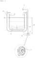
- FIG. 1 is a perspective view of a laundry treatment machine 1 according to an embodiment of the present invention
- FIG. 2 is a schematic diagram showing the configurations of a tub and a pump 11 of the laundry treatment machine 1, according to an embodiment of the present invention.
- the laundry treatment machine 1 is a top-loading laundry treatment machine in which laundry is inserted into a tub from above.
- the top-loading laundry treatment machine includes the concept of a washing machine for performing washing, rinsing and spin-drying processes after laundry is inserted, or a drying machine for performing a drying process after wet laundry is inserted, and the following description is focused on the washing machine.
- the washing machine 1 includes a casing for forming the exterior of the washing machine 1, manipulation keys for receiving a variety of control commands input by a user, a control panel for providing a user interface using, for example, a display for displaying information about an operation state of the washing machine 1, and a door for opening or closing an opening through which laundry enters or exits.
- the control panel includes an input unit including a plurality of manipulation keys for manipulating an operation state of the laundry treatment machine 1, and a display unit for displaying the operation state of the laundry treatment machine 1.
- the washing machine 1 includes the tub.
- the tub includes an outer tub 13 for accommodating water, and an inner tub 12 rotatably provided in the outer tub 13 to accommodate laundry.
- the washing machine 1 may include a pulsator 14 rotatably provided at the bottom of the tub and, more particular, at the bottom of the inner tub 12.
- a driving device (not shown) provides a driving force for rotating the inner tub 12 and/or the pulsator 14.
- a clutch (not shown) for selectively delivering the driving force of the driving device may be provided to rotate only the inner tub 12, to rotate only the pulsator 14, or to simultaneously rotate the inner tub 12 and the pulsator 14.
- the inner tub 12 has a plurality of holes (not shown) and thus water supplied into the inner tub 12 flows through the holes to the outer tub 13.
- a water inlet valve (not shown) for opening or closing a water inlet hose (not shown) may be provided to supply water into the tub.
- Water in the outer tub 13 is drained through a drain hose 15, and a drain valve (not shown) for opening or closing the drain hose 15, and the pump 11 for pumping water are provided.
- the pump 11 discharges water through the drain hose 15 to the outside of the washing machine 1, or supplies water through a circulation hose 16 into the tub again, depending on a rotation direction thereof.
- a spray nozzle 17 may be provided at an end of the circulation hose 16 and thus the circulated and re-supplied water may be sprayed.
- a water level sensor (not shown) senses the level of water. In this case, if water is supplied to a first point 18, the level of water corresponds to a height from the location of the drain hose 15 to the first point 18 and a level 19 is measured.
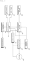
- FIG. 3 is a block diagram of the laundry treatment machine 1 according to an embodiment of the present invention.
- the washing machine 1 includes an input unit 170, an output unit 160, a water level sensor 156, a current sensor 152, a motor controller 120, a motor driver 130, a motor 140, a speed sensor 151, a driving controller 180, a driving device 190, and a main controller 110 for providing overall control to the washing machine 1.
- the washing machine 1 may further include a storage (not shown) for storing data.
- the motor 140 is a motor of the pump 1 mounted on the drain hose 15 for drainage and circulation of water, and the motor controller 120 and the motor driver 130 are used to control operation of the motor 140 of the pump 11.
- the washing machine 1 further includes a plurality of sensors and additional devices related to the driving device 190, and other elements such as a water inlet valve and a drain valve, descriptions thereof are omitted herein and the following description is focused on a configuration for controlling the pump 11.
- the input unit 170 includes a plurality of manipulation keys provided on the control panel, and may further include a specific input means such as a touchpad.
- the input unit 170 inputs setting data such as a washing mode, a washing temperature, a water level, or a reservation time, and inputs a control command for starting or stopping operation of the washing machine 1 depending on the setting data.
- setting data such as a washing mode, a washing temperature, a water level, or a reservation time
- the output unit 160 outputs the setting data input through the input unit 170, e.g., the washing mode, the washing temperature, or the water level, and outputs process information such as a current washing process state and a remaining washing time.
- the output unit 160 includes a display means for displaying the setting data or the process information in the form of text, a number, or an image.
- the output unit 160 may include a buzzer (not shown) or a speaker (not shown) for outputting a specific sound effect or an alarm, and a lamp (not shown) to be turned on or off to output an operation state or a warning.
- the storage stores basic data for controlling operation of the washing machine 1, control data for controlling the operation, input and output data, and data input from a plurality of sensors while the washing machine 1 operates.
- the driving controller 180 controls the driving device 190 to rotate based on a control command of the main controller 110.
- the driving device 190 includes another motor which rotates under control of the driving controller 180.
- the driving device 190 rotates at least one of the pulsator 14 or the inner tub 12.
- the water level sensor 156 includes at least one sensor and measures the water level 19 in the tub. As described above, if water is supplied to the first point 18, the water level 19 is measured and provided to the main controller 110 and the motor controller 120.
- the motor controller 120 generates a control signal for driving the motor 140 to operate the pump 11 depending on a control command of the main controller 110.
- the control signal generated in this case is a switching control signal, e.g., a pulse width modulation (PWM) signal.
- PWM pulse width modulation
- the motor controller 120 generates a revolutions per minute (RPM) signal for controlling a rotation speed of the motor 140, as a control signal depending on a sensed load state of water.
- RPM revolutions per minute
- the motor controller 120 outputs the PWM signal through a resistor-capacitor (RC) filter in such a manner that the PWM signal is input to the motor driver 130, and the RPM signal corresponds to a speed control voltage VSP, is set within a range from direct-current (DC) 1V to 4V, and is input to the motor driver 130.
- RC resistor-capacitor
- the motor driver 130 supplies a current having a specific magnitude as motor driving power to the motor 140 based on the control signals input from the motor controller 120, i.e., the PWM signal and the RPM signal.
- the motor driver 130 includes a sensorless integrated circuit (IC) and a protection circuit.
- the motor 140 rotates and water of the drain hose 15 is drained or circulated and supplied into the tub again.
- the motor 140 is a motor included in the pump 11 as described above.
- the motor 140 is a brushless DC (BLDC) motor.
- the motor 140 rotates clockwise or counterclockwise under control of the motor controller 120 and the motor driver 130, and thus the pump 11 drains or circulates water.
- water is drained if the motor 140 rotates clockwise, and is circulated and supplied through the circulation hose 16 into the tub again if the motor 140 rotates counterclockwise.
- the current sensor 152 measures the current supplied from the motor driver 130 to the motor 140 and inputs the same to the motor controller 120. In addition, the current sensor 152 inputs the sensed current to the main controller 110.
- the current sensor 152 includes an amplifier.
- the speed sensor 151 measures a rotation speed of the motor 140 and inputs the same to the motor controller 120. In this case, the speed sensor 151 measures the speed by receiving a voltage of the motor 140, and a comparative value between a DC link voltage and a distribution value, and calculates RPM corresponding to the voltage.
- the speed sensor 151 inputs the rotation speed of the motor 140 to the main controller 110.
- the main controller 110 controls input and output of data to and from the input unit 170 and the output unit 160, and controls the data to be stored in the storage.
- the main controller 110 sets operation of the washing machine 1 based on the setting data input through the input unit 170, and thus controls the washing machine 1 to operate.
- the washing machine 1 performs a washing process, a rinsing process, and a spin-drying process.
- a washer & dryer may further perform a drying process.
- the main controller 110 controls the display of the output unit 160 to display a washing mode, a washing time, a spin-drying time, a rinsing time, or a current operation state.
- the main controller 110 controls the drain valve not to drain water and controls the water inlet valve to supply water into the tub.
- the main controller 110 controls the pump 11 to operate while the washing process or the rinsing process is performed, in such a manner that water is supplied through the circulation hose 16 into the tub again, and applies a control command to the motor controller 120 to drain water when the washing process and the rinsing process are completed.
- the motor controller 120 generates a control signal for operation of the pump 11 depending on the control command of the main controller 110, and applies the same to the motor driver 130, and the motor driver 130 supplies motor driving power to the motor 140 to operate the pump 11.
- the main controller 110 receives the current of the motor 140 of the pump 11 from the current sensor 152, receives the rotation speed of the motor 140 from the speed sensor 151, and determines whether the level of water in the tub is zero based on the current and the rotation speed.
- the current input from the current sensor 152 and to the main controller 110 is a value converted by an analog to digital converter (ADC)
- the rotation speed input from the speed sensor 151 to the main controller 110 is a speed signal timer-processed by an encoder.
- the main controller 110 determines whether overcurrent occurs and determines the load of water, based on the current and the rotation speed of the motor 140.
- the main controller 110 inputs the results of determining whether the level of water is zero, whether overcurrent occurs, and the load, to the motor controller 120.
- the motor controller 120 receives a zero water level signal, an overcurrent signal, and load data from the main controller 110, and reflects the same in a control signal for controlling the motor 140 of the pump 11.
- the main controller 110 when a set process is performed, if the pump 11 operates for drainage or circulation of water, the main controller 110 applies a control command to the motor controller 120 to control the pump 11 to start operation depending on the water level of the water level sensor 156. Furthermore, the main controller 110 applies a control command to the motor controller 120 to control the pump 11 to stop operation depending on whether the level of water is zero, while the pump 11 operates.
- the main controller 110 determines whether the washing machine 1 normally operates, based on data input from a plurality of sensors, and outputs an error through the output unit 160 if an error occurs.
- FIG. 4 is a schematic diagram showing signal information depending on sensing of the load of the laundry treatment machine 1, according to an embodiment of the present invention.
- the main controller 110 determines whether the level of water is zero, determines whether overcurrent occurs, and determines the load of water, based on the current of the motor 140, which is input
- the main controller 110 determines that the level of water is zero, if the input rotation speed is increased and the current is reduced, according to a load sensing algorithm. In this case, the main controller 110 determines whether water is drained and the level of water is zero, in further consideration of the water level input from the water level sensor 156.
- the main controller 110 determines the load of water and determines whether overcurrent occurs, if the rotation speed of the motor 140 of the pump 11 is reduced and the current is increased.
- a zero water level signal, an overcurrent signal, and a load signal are input to the motor controller 120, and the current of the current sensor 152, the rotation speed of the speed sensor 151 (e.g., a currently measured RPM), and the water level of the water level sensor 156 are input to the motor controller 120.
- a target RPM of the motor 140 for driving the pump 11 is input from the main controller 110 to the motor controller 120.
- the motor controller 120 generates a PWM signal based on the input data, sets a rotation speed of the motor 140, and inputs the rotation speed to the motor driver 130, and the motor driver 130 supplies driving power based thereon to the motor 140.
- the current sensor 152 senses and inputs an output current input from the motor driver 130 to the motor 140, to the motor controller 120 and the main controller 110, and measures and inputs a rotation speed of the speed sensor 151 to the motor controller 120 and the main controller 110 if the motor 140 operates.
- the motor controller 120 varies control of the motor 140 based on the target RPM, the actually measured RPM, and the current value in consideration of the load state of water, whether the level of water is zero, and whether overcurrent occurs.
- the main controller 110 applies a control command to the motor controller 120 to stop or restart operation of the motor 140 based on the load state of water, whether the level of water is zero, whether overcurrent occurs, and variations in current value and rotation speed.
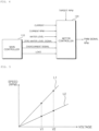
- FIG. 5 is a graph showing the relationship between a voltage and a rotation speed of the motor 140 in controlling the laundry treatment machine 1, according to an embodiment of the present invention.
- a first line L1 shows an unloaded state
- a second line L2 shows a loaded state of water.
- a rotation speed RPM of the motor 140 is increased in proportion to a speed control voltage VSP of the motor controller 120.
- the relationship between the voltage and the rotation speed in the loaded state and the relationship in the unloaded state are compared as described below.
- the rotation speed of the motor 140 measured when water is not loaded i.e., when the level of water is zero
- the rotation speed of the motor 140 measured when water is not loaded is higher compared to that measured when water is present.
- the rotation speed of the motor 140 is increased in proportion to the voltage depending on the load of the water.
- a drain filter if a drain filter is clogged with foreign substances, water may not be normally drained and thus a current for driving the motor 140 may be increased. In addition, it may be determined whether water is normally drained, based on a variation in the rotation speed of the motor 140 measured for a preset drain time.
- the main controller 110 may determine that an error occurs and thus output the error through the output unit 160.
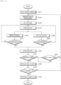
- FIG. 6 is a flowchart of a method for controlling the laundry treatment machine 1 outside the scope of the claimed invention.
- the main controller 110 applies a drain command to the motor controller 120 (S310).
- the motor controller 120 generates a control signal for controlling the motor 140 of the pump 11, and sets a voltage for setting a speed of the motor 140 (S320 and S330) .
- the motor driver 130 receives the control signal of the motor controller 120 and supplies driving power to the motor 140, and thus the motor 140 rotates and operates (S340).
- the speed sensor 151 measures the rotation speed of the motor 140 (S360), and applies the measured rotation speed to the main controller 110 and the motor controller 120.
- the motor controller 120 generates a control signal for subsequent control of the motor 140 based on the input rotation speed.
- the main controller 110 determines whether the measured rotation speed of the motor 140 is increased by a certain rate or more (S370). In this case, the main controller 110 determines whether the rotation speed of the motor 140 is increased by 33% or more compared to a premeasured rotation speed.
- the main controller 110 applies a motor stop command to the motor controller 120 (S400).
- the current sensor 152 measures a current applied from the motor driver 130 to the motor 140 (S380).
- the main controller 110 compares the measured current value to a previous current value, and determines whether the current is reduced (S390). For example, the main controller 110 may determine whether the current is reduced by 90% or more.
- the main controller 110 applies a motor stop command to the motor controller 120 (S400).
- the motor 140 continues operating. While the motor 140 operates, the rotation speed and the current value thereof are sensed and variations therein are monitored.
- the main controller 110 determines whether overcurrent is supplied to the motor 140, a load state, or whether the level of water is zero, based on the variations in the rotation speed and the current.
- the main controller 110 stops the motor 140, counts the number of times that the motor 140 stops, and determines whether the number of times that the motor 140 stops is equal to or greater than a reference number (S410).
- the main controller 110 applies a motor driving command to the motor controller 120 to drive the motor 140 again.
- the main controller 110 controls the water level sensor 156 to measure the level of water (S430).
- the main controller 110 determines whether water is completely drained to a designated level, based on the measured level of water (S450). If water is not completely drained, the motor 140 is driven again to operate the pump 11 again.
- the main controller 110 determines that drainage is completed (S460), and the method proceeds to a subsequent process.
- a load state of water and an error in drainage due to, for example, foreign substances are sensed and overcurrent supplied to a motor is determined depending on variations in rotation speed and current value of the motor.
- operation of the motor is controlled.
- the motor may be protected, may achieve noise reduction, and thus may be controlled more efficiently.
Landscapes
- Engineering & Computer Science (AREA)
- Textile Engineering (AREA)
- Power Engineering (AREA)
- Control Of Washing Machine And Dryer (AREA)
Claims (8)
- Wäschebehandlungsmaschine, aufweisend:eine äußere Wanne (13) zur Aufnahme von Wasser zum Waschen von Wäsche;einen Wasserstandssensor (156) zum Messen eines Wasserstands (19) in der äußeren Wanne (13); undeine Pumpe (11) zum Ablassen oder Umwälzen von Wasser, wobei die Pumpe (11) einen Motor (140) zum Betreiben der Pumpe (11) aufweist;einen Motorantrieb (130), um eine Betriebsleistung an den Motor (140) zu liefern;eine Motorsteuerung (120), um eine Drehzahl des Motors (140) einzustellen und um ein Signal zum Ansteuern des Motors (140) an den Motorantrieb (130) anzulegen;einen Stromsensor (152) zum Messen eines Stroms der vom Motorantrieb (130) an den Motor (140) gelieferten Betriebsleistung;einen Drehzahlsensor (151) zum Messen einer Drehzahl des Motors (140);
undeine Hauptsteuerung (110) zum Anlegen eines Steuerbefehls an die Motorsteuerung (120), um den Betrieb des Motors (140) zu starten oder zu stoppen,dadurch gekennzeichnet, dassdie Hauptsteuerung (110) dazu ausgelegt ist, den Motor (140) so anzusteuern, dass er in Reaktion auf das Ergebnis der Bestimmung eines Wasserladezustands und der Feststellung, ob der Pegel (19) des Wassers in der äußeren Wanne (13) Null ist, auf der Grundlage des von dem Stromsensor (152) gemessenen Stroms und der von dem Drehzahlsensor (151) gemessenen Drehzahl des Motors (140) stoppt,wobei die Hauptsteuerung (110) ferner dazu ausgelegt ist, festzustellen, wenn der Pegel (19) des Wassers in der äußeren Wanne (13) Null ist, und den Motor so anzusteuern, dass er stoppt, wenn die Drehzahl erhöht ist und der Strom verringert ist, undwobei die Hauptsteuerung (110) dazu ausgelegt ist, eine Anzahl von Malen zu zählen, die der Motor (140) stoppt, und auf der Grundlage des vom Wasserstandssensor (156) gemessenen Pegels (19) des Wassers in der äußeren Wanne (13) festzustellen, dass das Wasser vollständig abgelassen ist, wenn die Anzahl der Male, die der Motor (140) stoppt, gleich oder größer als eine Referenzanzahl ist. - Wäschebehandlungsmaschine nach Anspruch 1, wobei die Motorsteuerung (120) dazu ausgelegt ist, den Motor (140) zu stoppen, wenn ein Null-Wasserstandserfassungssignal oder ein Überstromerfassungssignal von der Hauptsteuerung (110) eingegeben wird.
- Wäschebehandlungsmaschine nach Anspruch 1, wobei die Hauptsteuerung (110) dazu ausgelegt ist, festzustellen, ob ein Überstrom auftritt, oder den Ladezustand zu bestimmen, wenn die Drehzahl des Motors (140) verringert und der Strom erhöht ist.
- Wäschebehandlungsmaschine nach Anspruch 1, wobei die Hauptsteuerung (110) dazu ausgelegt ist, den Motor (140) zum Stoppen anzusteuern, wenn die Drehzahl um eine bestimmte Rate oder mehr erhöht ist.
- Wäschebehandlungsmaschine nach Anspruch 5, wobei die Hauptsteuerung (110) dazu ausgelegt ist, den Motor (140) zum Stoppen anzusteuern, wenn die Drehzahl um 33 % oder mehr erhöht ist.
- Wäschebehandlungsmaschine nach Anspruch 1, wobei die Hauptsteuerung (110) dazu ausgelegt ist, den Motor (140) zum Stoppen anzusteuern, wenn der Strom um einen bestimmten Wert oder mehr verringert ist
- Wäschebehandlungsmaschine nach Anspruch 6, wobei die Hauptsteuerung (110) dazu ausgelegt ist, den Motor (140) zum Stoppen anzusteuern, wenn der Strom um 90% oder mehr verringert ist.
- Wäschebehandlungsmaschine nach Anspruch 1, wobei die Hauptsteuerung (110) dazu ausgelegt ist, die Anzahl von Malen zu zählen, die der Motor (140) stoppt, und den Motor (140) zum Stoppen und dann nach einer bestimmten Zeitspanne zum Weiterlaufen anzusteuern, wenn die Anzahl der Male, die der Motor (140) stoppt, kleiner als eine Referenzanzahl ist.
Applications Claiming Priority (2)
| Application Number | Priority Date | Filing Date | Title |
|---|---|---|---|
| KR1020140146384A KR102196183B1 (ko) | 2014-10-27 | 2014-10-27 | 세탁물 처리기기 및 그 제어방법 |
| PCT/KR2015/011376 WO2016068575A1 (ko) | 2014-10-27 | 2015-10-27 | 세탁물 처리기기 및 그 제어방법 |
Publications (3)
| Publication Number | Publication Date |
|---|---|
| EP3214218A1 EP3214218A1 (de) | 2017-09-06 |
| EP3214218A4 EP3214218A4 (de) | 2018-07-18 |
| EP3214218B1 true EP3214218B1 (de) | 2024-10-09 |
Family
ID=55791534
Family Applications (1)
| Application Number | Title | Priority Date | Filing Date |
|---|---|---|---|
| EP15855184.6A Active EP3214218B1 (de) | 2014-10-27 | 2015-10-27 | Kleiderbehandlungsvorrichtung |
Country Status (5)
| Country | Link |
|---|---|
| US (1) | US9863077B2 (de) |
| EP (1) | EP3214218B1 (de) |
| KR (1) | KR102196183B1 (de) |
| CN (1) | CN107109762B (de) |
| WO (1) | WO2016068575A1 (de) |
Families Citing this family (15)
| Publication number | Priority date | Publication date | Assignee | Title |
|---|---|---|---|---|
| CN206204637U (zh) * | 2016-07-20 | 2017-05-31 | 青岛海尔洗衣机有限公司 | 一种降低冷凝式滚筒干衣机排水噪音的装置 |
| KR102627102B1 (ko) * | 2017-01-11 | 2024-01-22 | 엘지전자 주식회사 | 의류처리장치 및 그의 제어방법 |
| KR102418952B1 (ko) | 2017-08-31 | 2022-07-08 | 삼성전자주식회사 | 음성인식 기능을 갖는 가전제품 |
| CN109487502B (zh) * | 2017-09-13 | 2022-09-06 | 青岛海尔洗涤电器有限公司 | 一种洗衣设备中途排水的控制方法及洗衣设备 |
| KR102544919B1 (ko) * | 2018-04-06 | 2023-06-16 | 엘지전자 주식회사 | 세탁물처리장치 및 제어방법 |
| KR102056168B1 (ko) | 2018-04-19 | 2019-12-16 | 엘지전자 주식회사 | 세탁물 처리기기 |
| KR102603619B1 (ko) | 2018-07-06 | 2023-11-16 | 엘지전자 주식회사 | 배수펌프 구동장치, 및 이를 구비한 세탁물 처리기기 |
| KR102627647B1 (ko) * | 2019-01-21 | 2024-01-19 | 엘지전자 주식회사 | 세탁물 처리기기 |
| CN111850948B (zh) * | 2019-04-17 | 2022-11-15 | 重庆海尔洗衣机有限公司 | 一种洗衣机水泵的控制方法及洗衣机水泵 |
| KR102842495B1 (ko) * | 2019-12-05 | 2025-08-06 | 삼성전자주식회사 | 의류 처리 장치 및 그의 제어 방법 |
| CN111431441B (zh) * | 2020-04-10 | 2022-01-11 | 宁波奥克斯电气股份有限公司 | 电机转速控制方法、装置、空调器及存储介质 |
| CN112853676A (zh) * | 2020-12-31 | 2021-05-28 | 长虹美菱股份有限公司 | 一种排水泵主动降噪的脱水控制方法 |
| EP4075663A1 (de) * | 2021-04-15 | 2022-10-19 | Vestel Elektronik Sanayi ve Ticaret A.S. | Motorsteuerung, waschmaschine und verfahren |
| CN114158995B (zh) * | 2021-11-09 | 2024-03-19 | 佛山市百斯特电器科技有限公司 | 一种故障识别的方法及洗涤设备 |
| KR20230118336A (ko) * | 2022-02-04 | 2023-08-11 | 엘지전자 주식회사 | 의류처리장치 |
Family Cites Families (11)
| Publication number | Priority date | Publication date | Assignee | Title |
|---|---|---|---|---|
| KR960037945A (ko) * | 1995-04-29 | 1996-11-19 | 배순훈 | 세탁기의 배수이상감지방법 |
| KR970027459A (ko) * | 1995-11-30 | 1997-06-24 | 배순훈 | 세탁기의 배수펌프제어방법 |
| KR100280605B1 (ko) * | 1998-12-29 | 2001-02-01 | 구자홍 | 드럼세탁기의 급수밸브 고장시 세탁수를 배수시키는 방법 |
| US7810362B2 (en) * | 2005-11-04 | 2010-10-12 | Fisher & Paykel Appliances Ltd. | Recirculation control in a washing machine |
| KR100889817B1 (ko) * | 2007-04-03 | 2009-03-20 | 삼성전자주식회사 | 세탁기 및 그 제어방법 |
| KR100891912B1 (ko) * | 2007-09-04 | 2009-04-08 | 엘지전자 주식회사 | 세탁물 처리장치의 제어방법. |
| JP5489328B2 (ja) * | 2009-08-24 | 2014-05-14 | 株式会社東芝 | ドラム式洗濯機 |
| EP2471993B1 (de) * | 2009-08-24 | 2019-10-30 | Toshiba Lifestyle Products & Services Corporation | Trommelwaschmaschine |
| JP2011250848A (ja) * | 2010-05-31 | 2011-12-15 | Sharp Corp | 洗濯機 |
| US20120005840A1 (en) * | 2010-07-06 | 2012-01-12 | Jang Hoyong | Washing machine and method for controlling the same |
| CN103930609B (zh) * | 2011-11-14 | 2016-01-06 | 松下电器产业株式会社 | 滚筒式洗衣机 |
-
2014
- 2014-10-27 KR KR1020140146384A patent/KR102196183B1/ko active Active
-
2015
- 2015-10-27 US US14/923,827 patent/US9863077B2/en active Active
- 2015-10-27 EP EP15855184.6A patent/EP3214218B1/de active Active
- 2015-10-27 WO PCT/KR2015/011376 patent/WO2016068575A1/ko not_active Ceased
- 2015-10-27 CN CN201580071026.8A patent/CN107109762B/zh active Active
Also Published As
| Publication number | Publication date |
|---|---|
| EP3214218A1 (de) | 2017-09-06 |
| US9863077B2 (en) | 2018-01-09 |
| KR102196183B1 (ko) | 2020-12-29 |
| WO2016068575A1 (ko) | 2016-05-06 |
| EP3214218A4 (de) | 2018-07-18 |
| CN107109762A (zh) | 2017-08-29 |
| KR20160049367A (ko) | 2016-05-09 |
| US20160115632A1 (en) | 2016-04-28 |
| CN107109762B (zh) | 2020-05-12 |
Similar Documents
| Publication | Publication Date | Title |
|---|---|---|
| EP3214218B1 (de) | Kleiderbehandlungsvorrichtung | |
| US11326297B2 (en) | Washing machine with heater and multiple tubs and control method thereof | |
| US10934657B2 (en) | Washer dryer machine and control method | |
| EP2848726B1 (de) | Verfahren zur Steuerung einer Waschmaschine | |
| US11846060B2 (en) | Laundry treatment apparatus and control method thereof | |
| KR102476288B1 (ko) | 세탁물처리장치 및 제어방법 | |
| US20160194803A1 (en) | A Method for Operating a Washing Machine During a Washing Cycle | |
| US9752268B2 (en) | Control method of washing machine | |
| JP2019025136A (ja) | 洗濯機 | |
| US20190032268A1 (en) | Laundry processing apparatus and control method thereof | |
| CN111315926B (zh) | 衣物处理装置及其控制方法 | |
| KR20150041855A (ko) | 세탁기 및 그 제어 방법 | |
| EP3073006A1 (de) | Verfahren zur detektion einer fehlfunktion einer umwälzpumpe in einer waschmaschine und waschmaschine mit solch einem verfahren | |
| CN111101318A (zh) | 衣物处理装置的制动检测方法、装置和计算机设备 | |
| JP4656661B2 (ja) | 洗濯機 | |
| KR20170085888A (ko) | 세탁물 처리기기 및 그 제어방법 | |
| KR20230103589A (ko) | 세탁기 및 그 제어 방법 | |
| KR20150118429A (ko) | 세탁기 및 그 제어 방법 | |
| KR101585449B1 (ko) | 세탁기의 제어 방법 | |
| EP3314051B1 (de) | Stromversorgungsregulierung in wäschebehandlungsmaschinen oder geschirrspülern | |
| JP2020081459A (ja) | 洗濯機 | |
| KR100712848B1 (ko) | 세탁기의 제어 방법 | |
| KR20120012213A (ko) | 세탁기의 제어방법 | |
| EP3314052A1 (de) | Stromversorgungsregulierung in wäschebehandlungsmaschinen oder geschirrspülern | |
| JP2016054848A (ja) | 食器洗浄機 |
Legal Events
| Date | Code | Title | Description |
|---|---|---|---|
| STAA | Information on the status of an ep patent application or granted ep patent |
Free format text: STATUS: THE INTERNATIONAL PUBLICATION HAS BEEN MADE |
|
| PUAI | Public reference made under article 153(3) epc to a published international application that has entered the european phase |
Free format text: ORIGINAL CODE: 0009012 |
|
| STAA | Information on the status of an ep patent application or granted ep patent |
Free format text: STATUS: REQUEST FOR EXAMINATION WAS MADE |
|
| 17P | Request for examination filed |
Effective date: 20170526 |
|
| AK | Designated contracting states |
Kind code of ref document: A1 Designated state(s): AL AT BE BG CH CY CZ DE DK EE ES FI FR GB GR HR HU IE IS IT LI LT LU LV MC MK MT NL NO PL PT RO RS SE SI SK SM TR |
|
| AX | Request for extension of the european patent |
Extension state: BA ME |
|
| DAV | Request for validation of the european patent (deleted) | ||
| DAX | Request for extension of the european patent (deleted) | ||
| A4 | Supplementary search report drawn up and despatched |
Effective date: 20180619 |
|
| RIC1 | Information provided on ipc code assigned before grant |
Ipc: D06F 39/08 20060101ALN20180611BHEP Ipc: D06F 33/02 20060101AFI20180611BHEP Ipc: H02P 29/02 20160101ALI20180611BHEP Ipc: H02P 1/16 20060101ALN20180611BHEP Ipc: H02P 3/06 20060101ALN20180611BHEP |
|
| STAA | Information on the status of an ep patent application or granted ep patent |
Free format text: STATUS: EXAMINATION IS IN PROGRESS |
|
| 17Q | First examination report despatched |
Effective date: 20210617 |
|
| REG | Reference to a national code |
Ref country code: DE Ref legal event code: R079 Free format text: PREVIOUS MAIN CLASS: D06F0039080000 Ipc: H02P0029020000 Ref country code: DE Ref legal event code: R079 Ref document number: 602015090106 Country of ref document: DE Free format text: PREVIOUS MAIN CLASS: D06F0039080000 Ipc: H02P0029020000 |
|
| GRAP | Despatch of communication of intention to grant a patent |
Free format text: ORIGINAL CODE: EPIDOSNIGR1 |
|
| STAA | Information on the status of an ep patent application or granted ep patent |
Free format text: STATUS: GRANT OF PATENT IS INTENDED |
|
| RIC1 | Information provided on ipc code assigned before grant |
Ipc: D06F 105/46 20200101ALN20240418BHEP Ipc: D06F 105/08 20200101ALN20240418BHEP Ipc: D06F 105/02 20200101ALN20240418BHEP Ipc: D06F 103/44 20200101ALN20240418BHEP Ipc: D06F 103/24 20200101ALN20240418BHEP Ipc: D06F 103/18 20200101ALN20240418BHEP Ipc: H02P 3/06 20060101ALN20240418BHEP Ipc: H02P 1/16 20060101ALN20240418BHEP Ipc: D06F 33/38 20200101ALI20240418BHEP Ipc: D06F 33/34 20200101ALI20240418BHEP Ipc: D06F 39/08 20060101ALI20240418BHEP Ipc: H02P 29/02 20160101AFI20240418BHEP |
|
| INTG | Intention to grant announced |
Effective date: 20240506 |
|
| GRAS | Grant fee paid |
Free format text: ORIGINAL CODE: EPIDOSNIGR3 |
|
| GRAA | (expected) grant |
Free format text: ORIGINAL CODE: 0009210 |
|
| STAA | Information on the status of an ep patent application or granted ep patent |
Free format text: STATUS: THE PATENT HAS BEEN GRANTED |
|
| AK | Designated contracting states |
Kind code of ref document: B1 Designated state(s): AL AT BE BG CH CY CZ DE DK EE ES FI FR GB GR HR HU IE IS IT LI LT LU LV MC MK MT NL NO PL PT RO RS SE SI SK SM TR |
|
| REG | Reference to a national code |
Ref country code: CH Ref legal event code: EP |
|
| REG | Reference to a national code |
Ref country code: DE Ref legal event code: R096 Ref document number: 602015090106 Country of ref document: DE |
|
| REG | Reference to a national code |
Ref country code: IE Ref legal event code: FG4D |
|
| REG | Reference to a national code |
Ref country code: LT Ref legal event code: MG9D |
|
| REG | Reference to a national code |
Ref country code: NL Ref legal event code: MP Effective date: 20241009 |
|
| REG | Reference to a national code |
Ref country code: AT Ref legal event code: MK05 Ref document number: 1731687 Country of ref document: AT Kind code of ref document: T Effective date: 20241009 |
|
| PG25 | Lapsed in a contracting state [announced via postgrant information from national office to epo] |
Ref country code: NL Free format text: LAPSE BECAUSE OF FAILURE TO SUBMIT A TRANSLATION OF THE DESCRIPTION OR TO PAY THE FEE WITHIN THE PRESCRIBED TIME-LIMIT Effective date: 20241009 |
|
| PG25 | Lapsed in a contracting state [announced via postgrant information from national office to epo] |
Ref country code: NL Free format text: LAPSE BECAUSE OF FAILURE TO SUBMIT A TRANSLATION OF THE DESCRIPTION OR TO PAY THE FEE WITHIN THE PRESCRIBED TIME-LIMIT Effective date: 20241009 |
|
| PG25 | Lapsed in a contracting state [announced via postgrant information from national office to epo] |
Ref country code: IS Free format text: LAPSE BECAUSE OF FAILURE TO SUBMIT A TRANSLATION OF THE DESCRIPTION OR TO PAY THE FEE WITHIN THE PRESCRIBED TIME-LIMIT Effective date: 20250209 Ref country code: HR Free format text: LAPSE BECAUSE OF FAILURE TO SUBMIT A TRANSLATION OF THE DESCRIPTION OR TO PAY THE FEE WITHIN THE PRESCRIBED TIME-LIMIT Effective date: 20241009 Ref country code: PT Free format text: LAPSE BECAUSE OF FAILURE TO SUBMIT A TRANSLATION OF THE DESCRIPTION OR TO PAY THE FEE WITHIN THE PRESCRIBED TIME-LIMIT Effective date: 20250210 |
|
| PG25 | Lapsed in a contracting state [announced via postgrant information from national office to epo] |
Ref country code: FI Free format text: LAPSE BECAUSE OF FAILURE TO SUBMIT A TRANSLATION OF THE DESCRIPTION OR TO PAY THE FEE WITHIN THE PRESCRIBED TIME-LIMIT Effective date: 20241009 |
|
| PG25 | Lapsed in a contracting state [announced via postgrant information from national office to epo] |
Ref country code: BG Free format text: LAPSE BECAUSE OF FAILURE TO SUBMIT A TRANSLATION OF THE DESCRIPTION OR TO PAY THE FEE WITHIN THE PRESCRIBED TIME-LIMIT Effective date: 20241009 |
|
| PG25 | Lapsed in a contracting state [announced via postgrant information from national office to epo] |
Ref country code: ES Free format text: LAPSE BECAUSE OF FAILURE TO SUBMIT A TRANSLATION OF THE DESCRIPTION OR TO PAY THE FEE WITHIN THE PRESCRIBED TIME-LIMIT Effective date: 20241009 |
|
| PG25 | Lapsed in a contracting state [announced via postgrant information from national office to epo] |
Ref country code: NO Free format text: LAPSE BECAUSE OF FAILURE TO SUBMIT A TRANSLATION OF THE DESCRIPTION OR TO PAY THE FEE WITHIN THE PRESCRIBED TIME-LIMIT Effective date: 20250109 |
|
| PG25 | Lapsed in a contracting state [announced via postgrant information from national office to epo] |
Ref country code: LV Free format text: LAPSE BECAUSE OF FAILURE TO SUBMIT A TRANSLATION OF THE DESCRIPTION OR TO PAY THE FEE WITHIN THE PRESCRIBED TIME-LIMIT Effective date: 20241009 Ref country code: GR Free format text: LAPSE BECAUSE OF FAILURE TO SUBMIT A TRANSLATION OF THE DESCRIPTION OR TO PAY THE FEE WITHIN THE PRESCRIBED TIME-LIMIT Effective date: 20250110 Ref country code: AT Free format text: LAPSE BECAUSE OF FAILURE TO SUBMIT A TRANSLATION OF THE DESCRIPTION OR TO PAY THE FEE WITHIN THE PRESCRIBED TIME-LIMIT Effective date: 20241009 |
|
| PG25 | Lapsed in a contracting state [announced via postgrant information from national office to epo] |
Ref country code: PL Free format text: LAPSE BECAUSE OF FAILURE TO SUBMIT A TRANSLATION OF THE DESCRIPTION OR TO PAY THE FEE WITHIN THE PRESCRIBED TIME-LIMIT Effective date: 20241009 |
|
| PG25 | Lapsed in a contracting state [announced via postgrant information from national office to epo] |
Ref country code: RS Free format text: LAPSE BECAUSE OF FAILURE TO SUBMIT A TRANSLATION OF THE DESCRIPTION OR TO PAY THE FEE WITHIN THE PRESCRIBED TIME-LIMIT Effective date: 20250109 |
|
| REG | Reference to a national code |
Ref country code: CH Ref legal event code: PL |
|
| PG25 | Lapsed in a contracting state [announced via postgrant information from national office to epo] |
Ref country code: SM Free format text: LAPSE BECAUSE OF FAILURE TO SUBMIT A TRANSLATION OF THE DESCRIPTION OR TO PAY THE FEE WITHIN THE PRESCRIBED TIME-LIMIT Effective date: 20241009 |
|
| PG25 | Lapsed in a contracting state [announced via postgrant information from national office to epo] |
Ref country code: MC Free format text: LAPSE BECAUSE OF FAILURE TO SUBMIT A TRANSLATION OF THE DESCRIPTION OR TO PAY THE FEE WITHIN THE PRESCRIBED TIME-LIMIT Effective date: 20241009 |
|
| PG25 | Lapsed in a contracting state [announced via postgrant information from national office to epo] |
Ref country code: DK Free format text: LAPSE BECAUSE OF FAILURE TO SUBMIT A TRANSLATION OF THE DESCRIPTION OR TO PAY THE FEE WITHIN THE PRESCRIBED TIME-LIMIT Effective date: 20241009 |
|
| REG | Reference to a national code |
Ref country code: DE Ref legal event code: R097 Ref document number: 602015090106 Country of ref document: DE |
|
| PG25 | Lapsed in a contracting state [announced via postgrant information from national office to epo] |
Ref country code: BE Free format text: LAPSE BECAUSE OF NON-PAYMENT OF DUE FEES Effective date: 20241031 Ref country code: LU Free format text: LAPSE BECAUSE OF NON-PAYMENT OF DUE FEES Effective date: 20241027 |
|
| PG25 | Lapsed in a contracting state [announced via postgrant information from national office to epo] |
Ref country code: EE Free format text: LAPSE BECAUSE OF FAILURE TO SUBMIT A TRANSLATION OF THE DESCRIPTION OR TO PAY THE FEE WITHIN THE PRESCRIBED TIME-LIMIT Effective date: 20241009 |
|
| PG25 | Lapsed in a contracting state [announced via postgrant information from national office to epo] |
Ref country code: CH Free format text: LAPSE BECAUSE OF NON-PAYMENT OF DUE FEES Effective date: 20241031 |
|
| PG25 | Lapsed in a contracting state [announced via postgrant information from national office to epo] |
Ref country code: RO Free format text: LAPSE BECAUSE OF FAILURE TO SUBMIT A TRANSLATION OF THE DESCRIPTION OR TO PAY THE FEE WITHIN THE PRESCRIBED TIME-LIMIT Effective date: 20241009 |
|
| PG25 | Lapsed in a contracting state [announced via postgrant information from national office to epo] |
Ref country code: SK Free format text: LAPSE BECAUSE OF FAILURE TO SUBMIT A TRANSLATION OF THE DESCRIPTION OR TO PAY THE FEE WITHIN THE PRESCRIBED TIME-LIMIT Effective date: 20241009 |
|
| PG25 | Lapsed in a contracting state [announced via postgrant information from national office to epo] |
Ref country code: CZ Free format text: LAPSE BECAUSE OF FAILURE TO SUBMIT A TRANSLATION OF THE DESCRIPTION OR TO PAY THE FEE WITHIN THE PRESCRIBED TIME-LIMIT Effective date: 20241009 |
|
| REG | Reference to a national code |
Ref country code: BE Ref legal event code: MM Effective date: 20241031 |
|
| PLBE | No opposition filed within time limit |
Free format text: ORIGINAL CODE: 0009261 |
|
| STAA | Information on the status of an ep patent application or granted ep patent |
Free format text: STATUS: NO OPPOSITION FILED WITHIN TIME LIMIT |
|
| PG25 | Lapsed in a contracting state [announced via postgrant information from national office to epo] |
Ref country code: SE Free format text: LAPSE BECAUSE OF FAILURE TO SUBMIT A TRANSLATION OF THE DESCRIPTION OR TO PAY THE FEE WITHIN THE PRESCRIBED TIME-LIMIT Effective date: 20241009 |
|
| 26N | No opposition filed |
Effective date: 20250710 |
|
| GBPC | Gb: european patent ceased through non-payment of renewal fee |
Effective date: 20250109 |
|
| PGFP | Annual fee paid to national office [announced via postgrant information from national office to epo] |
Ref country code: IT Payment date: 20250909 Year of fee payment: 11 |
|
| PG25 | Lapsed in a contracting state [announced via postgrant information from national office to epo] |
Ref country code: GB Free format text: LAPSE BECAUSE OF NON-PAYMENT OF DUE FEES Effective date: 20250109 |
|
| PG25 | Lapsed in a contracting state [announced via postgrant information from national office to epo] |
Ref country code: FR Free format text: LAPSE BECAUSE OF NON-PAYMENT OF DUE FEES Effective date: 20241209 |
|
| PG25 | Lapsed in a contracting state [announced via postgrant information from national office to epo] |
Ref country code: IE Free format text: LAPSE BECAUSE OF NON-PAYMENT OF DUE FEES Effective date: 20241027 |
|
| PGFP | Annual fee paid to national office [announced via postgrant information from national office to epo] |
Ref country code: DE Payment date: 20250908 Year of fee payment: 11 |
|
| PG25 | Lapsed in a contracting state [announced via postgrant information from national office to epo] |
Ref country code: CY Free format text: LAPSE BECAUSE OF FAILURE TO SUBMIT A TRANSLATION OF THE DESCRIPTION OR TO PAY THE FEE WITHIN THE PRESCRIBED TIME-LIMIT; INVALID AB INITIO Effective date: 20151027 |
|
| PG25 | Lapsed in a contracting state [announced via postgrant information from national office to epo] |
Ref country code: HU Free format text: LAPSE BECAUSE OF FAILURE TO SUBMIT A TRANSLATION OF THE DESCRIPTION OR TO PAY THE FEE WITHIN THE PRESCRIBED TIME-LIMIT; INVALID AB INITIO Effective date: 20151027 |