EP3213069B1 - Vorrichtung zur analyse von urin - Google Patents
Vorrichtung zur analyse von urin Download PDFInfo
- Publication number
- EP3213069B1 EP3213069B1 EP15775435.9A EP15775435A EP3213069B1 EP 3213069 B1 EP3213069 B1 EP 3213069B1 EP 15775435 A EP15775435 A EP 15775435A EP 3213069 B1 EP3213069 B1 EP 3213069B1
- Authority
- EP
- European Patent Office
- Prior art keywords
- urine
- urine test
- test strip
- discharge
- region
- Prior art date
- Legal status (The legal status is an assumption and is not a legal conclusion. Google has not performed a legal analysis and makes no representation as to the accuracy of the status listed.)
- Active
Links
Images


Classifications
-
- G—PHYSICS
- G01—MEASURING; TESTING
- G01N—INVESTIGATING OR ANALYSING MATERIALS BY DETERMINING THEIR CHEMICAL OR PHYSICAL PROPERTIES
- G01N15/00—Investigating characteristics of particles; Investigating permeability, pore-volume or surface-area of porous materials
- G01N15/10—Investigating individual particles
- G01N15/14—Optical investigation techniques, e.g. flow cytometry
- G01N15/1456—Optical investigation techniques, e.g. flow cytometry without spatial resolution of the texture or inner structure of the particle, e.g. processing of pulse signals
- G01N15/1459—Optical investigation techniques, e.g. flow cytometry without spatial resolution of the texture or inner structure of the particle, e.g. processing of pulse signals the analysis being performed on a sample stream
-
- A—HUMAN NECESSITIES
- A61—MEDICAL OR VETERINARY SCIENCE; HYGIENE
- A61B—DIAGNOSIS; SURGERY; IDENTIFICATION
- A61B10/00—Instruments for taking body samples for diagnostic purposes; Other methods or instruments for diagnosis, e.g. for vaccination diagnosis, sex determination or ovulation-period determination; Throat striking implements
- A61B10/0045—Devices for taking samples of body liquids
- A61B10/007—Devices for taking samples of body liquids for taking urine samples
-
- A—HUMAN NECESSITIES
- A61—MEDICAL OR VETERINARY SCIENCE; HYGIENE
- A61B—DIAGNOSIS; SURGERY; IDENTIFICATION
- A61B5/00—Measuring for diagnostic purposes; Identification of persons
- A61B5/20—Measuring for diagnostic purposes; Identification of persons for measuring urological functions restricted to the evaluation of the urinary system
- A61B5/207—Sensing devices adapted to collect urine
- A61B5/208—Sensing devices adapted to collect urine adapted to determine urine quantity, e.g. flow, volume
-
- G—PHYSICS
- G01—MEASURING; TESTING
- G01N—INVESTIGATING OR ANALYSING MATERIALS BY DETERMINING THEIR CHEMICAL OR PHYSICAL PROPERTIES
- G01N15/00—Investigating characteristics of particles; Investigating permeability, pore-volume or surface-area of porous materials
- G01N15/10—Investigating individual particles
- G01N15/14—Optical investigation techniques, e.g. flow cytometry
-
- G—PHYSICS
- G01—MEASURING; TESTING
- G01N—INVESTIGATING OR ANALYSING MATERIALS BY DETERMINING THEIR CHEMICAL OR PHYSICAL PROPERTIES
- G01N33/00—Investigating or analysing materials by specific methods not covered by groups G01N1/00 - G01N31/00
- G01N33/48—Biological material, e.g. blood, urine; Haemocytometers
- G01N33/483—Physical analysis of biological material
- G01N33/487—Physical analysis of biological material of liquid biological material
- G01N33/493—Physical analysis of biological material of liquid biological material urine
-
- E—FIXED CONSTRUCTIONS
- E03—WATER SUPPLY; SEWERAGE
- E03D—WATER-CLOSETS OR URINALS WITH FLUSHING DEVICES; FLUSHING VALVES THEREFOR
- E03D11/00—Other component parts of water-closets, e.g. noise-reducing means in the flushing system, flushing pipes mounted in the bowl, seals for the bowl outlet, devices preventing overflow of the bowl contents; devices forming a water seal in the bowl after flushing, devices eliminating obstructions in the bowl outlet or preventing backflow of water and excrements from the waterpipe
- E03D11/02—Water-closet bowls ; Bowls with a double odour seal optionally with provisions for a good siphonic action; siphons as part of the bowl
-
- G—PHYSICS
- G01—MEASURING; TESTING
- G01N—INVESTIGATING OR ANALYSING MATERIALS BY DETERMINING THEIR CHEMICAL OR PHYSICAL PROPERTIES
- G01N15/00—Investigating characteristics of particles; Investigating permeability, pore-volume or surface-area of porous materials
- G01N15/10—Investigating individual particles
- G01N15/14—Optical investigation techniques, e.g. flow cytometry
- G01N2015/1486—Counting the particles
-
- G—PHYSICS
- G01—MEASURING; TESTING
- G01N—INVESTIGATING OR ANALYSING MATERIALS BY DETERMINING THEIR CHEMICAL OR PHYSICAL PROPERTIES
- G01N21/00—Investigating or analysing materials by the use of optical means, i.e. using sub-millimetre waves, infrared, visible or ultraviolet light
- G01N21/17—Systems in which incident light is modified in accordance with the properties of the material investigated
- G01N21/47—Scattering, i.e. diffuse reflection
- G01N2021/4704—Angular selective
- G01N2021/4707—Forward scatter; Low angle scatter
Definitions
- the invention relates to a device for analyzing urine and a sanitary device comprising such a device.
- Devices for the analysis of urine and optionally other endogenous fluids are known and are generally used to analyze a certain amount of urine with regard to their chemical or proportionate composition.
- this urine test strips are used, which are contacted with a certain amount of urine.
- the evaluation or observation of a change of an optically detectable parameter, d. H. In particular, a color change, a urine test strip side analysis area allows conclusions about the chemical or proportionate composition of the urine.
- a smart toilet having a urine collection device through which urine can be directed to an analyzer.
- the urine is introduced into a translucent cuvette, from which it can also be removed again, wherein a pumping device is provided for insertion and removal.
- a light source is provided, with which light can be radiated onto the cuvette, and at least one light sensor, light source and light sensor being aligned with one another such that an absorption and a scattered light measurement on the urine sample can be carried out.
- a color indicator supply and disposal system is provided for introducing and displaying a color indicator in and out of the cuvette and disposing of the color indicator after it has been used.
- the invention is therefore based on the object of specifying a contrast improved device for the analysis of urine.
- a device for analyzing urine which device at least comprises: a supply and discharge device, which is adapted for supplying a certain amount of urine in a at least one analysis region having analysis chamber of a urine test strip and for discharging a certain amount of urine from at least one analysis area having analysis chamber of a urine test strip, wherein the supply and discharge means at least one movably mounted feed and / or discharge element for supplying a specific amount of urine into a supply region of the analysis chamber of the urine test strip and / or for discharging a certain amount of urine from a discharge of the analysis chamber of the urine test strip, and a detection device, which detects at least a portion of at least one optically detectable parameter which changes optically detectable as a function of the composition of a urine quantity in contact with it, of the or a corresponding analysis region of the or an e atom urine test strip and for generating a detection information, which at least one optically detected parameter of the or a corresponding analysis area or a
- the device according to the invention for the analysis of urine hereinafter referred to as device, comprises as essential components a supply and discharge device and a detection device.
- the device may also comprise a plurality of supply and discharge devices or a plurality of detection devices.
- the supply and discharge device is used to supply a certain amount of urine in at least one analysis area having analysis chamber of a urine test strip and the discharge of a certain amount of urine from at least one analysis area having analysis chamber of a urine test strip. Accordingly, the supply and discharge device at least one movably mounted supply and / or discharge element for supplying a certain amount of urine in a supply area of the analysis chamber of the urine test strip and / or for discharging a certain amount of urine from a discharge of the analysis chamber of the urine test strip.
- the supply and discharge device or the at least one associated supply and / or discharge element By means of the supply and discharge device or the at least one associated supply and / or discharge element, it is thus possible to supply and / or discharge a specific quantity of urine, generally a certain amount of fluid, into a corresponding supply region or from a corresponding discharge region and thus into one or from a urine test strip side analysis chamber, in which a corresponding analysis area is present realize.
- the supply and discharge of a certain amount of urine basically a single supply and discharge element is possible, which serves both the supply of a certain amount of urine in a corresponding feed and the discharge of a certain amount of urine from a corresponding discharge, has the supply and discharge device typically at least one separate delivery member for delivering a given amount of urine into a respective delivery area and at least one separate discharge element for discharging a particular amount of urine from a respective discharge area.
- the movable mounting of a corresponding supply and / or discharge element allows targeted movements of this on corresponding urine test strip side feed and Abpublished sese respectively from corresponding urine test strip side feed and Abvant Schlen away.
- the movement of a corresponding supply and / or discharge element is typically possible between two movement end points.
- a first movement end point defined by the fact that in this a supply of a certain Amount of urine in a corresponding urine test strip side feed area or a discharge of a certain amount of urine from a corresponding urine test strip side discharge area is possible.
- a second movement end point is correspondingly defined by the fact that it is not possible to supply a specific quantity of urine into a corresponding urine test strip-side feed area or to remove a certain amount of urine from a corresponding urine test strip-side discharge area.
- a plurality of supply and / or discharge elements are provided, they can be moved along the same or non-uniform axes of movement or movement paths.
- the movement of the supply and / or discharge elements can take place at the same time or with a time delay.
- the movement of several feed and / or discharge elements expediently takes place simultaneously along parallel axes of movement or movement paths.
- the detection device is used to detect an at least section-wise change of at least one optically detectable parameter of a corresponding analysis region of a urine test strip.
- the optically detectable parameter changes in an optically detectable manner as a function of the composition of a quantity of urine wetting or contacting the analysis area, ie, for example, by changing the color and / or by changing the color intensity. Accordingly, the color or color intensity of the analysis area is a corresponding optically detectable parameter.
- the detection device comprises suitable, in particular optical, detection means. In such a detection means, it may, for. B. to act one or more optical scanner.
- the detection device In addition to detecting an at least section-wise change of at least one optically detectable parameter of a corresponding urine test strip-side analysis region, the detection device also serves to generate a detection information.
- An acquisition information generated by the detection device describes at least one optically detectable or detected parameter of the analysis area or a change of such.
- a detection information z. B. describe a color, a color intensity or a color change of the analysis area.
- the detection device is expediently designed for communication with at least one evaluation device, which is used to evaluate detection information generated by the detection device and to determine evaluation information describing an amount of urine present on the analysis area of the urine test strip, the detection information can be transmitted to corresponding evaluation devices in which On the basis of the detection information, conclusions can be drawn about the proportional or chemical composition of the amount of urine applied to the analysis area.
- the device expediently comprises a transmitting and / or receiving device associated with the detection device, which enables a wired or wireless transmission of corresponding detection information.
- the device can sonach, z. B. by means of Bluetooth, WLAN, etc., also to a local or global data network, d. H. z. B. connected to a local intranet or the Internet, or be involved in such.
- the operation of the supply and discharge device as well as the operation of the detection device is typically controlled via an associated device-side control device.
- At least one control regulation is typically stored in the control device, according to which a concerted, ie coordinated, control of the operation of the supply and discharge device, the detection device and optionally further, in particular of the device according to the invention, Facilities is possible.
- the latter include, in particular, the following devices to be explained below: pressure-determining devices, pump devices and valve devices connected in a bypass line.
- Different operating modes of the device according to the invention can be realized via the control device or the at least one control regulation stored in it.
- Corresponding modes of operation include, in particular, removal of a particular amount of urine, delivery of the or a sample of urine collected in an urine test strip analysis chamber, removal of the or a sample of urine strip sample taken from a urine test strip analysis chamber, rinses of the delivery and removal devices, rinses of the delivery and / or AbDOMiano, rinsing certain certain leading into the supply and / or discharge elements line sections or leads and discharges, rinsing a urine test strip, d. H. in particular a urine test strip side analysis chamber, etc. before.
- Corresponding operating modes of the device according to the invention can be activated or deactivated in different ways, or can be activated or deactivated.
- the activation or deactivation for example, by means of mobile terminals, including z.
- mobile phones, smart phones, laptops, tablets, etc. are understood, which can communicate via a communication link with a device-side transmitting and / or receiving device.
- a control can for example also be done by voice command, the device is equipped in this case with a suitable speech recognition device.
- Corresponding operating modes of the device can of course also be fully or partially automatically activated or deactivated.
- the device according to the invention enables a comparatively simple and integrated analysis of urine and thus represents an improvement over the prior art described at the outset.
- the device according to the invention can, as will be explained below, be assigned to a sanitary facility comprising a water closet, in short a WC, or integrated into such a sanitary facility.
- appropriate analyzes of urine, as well as of other bodily excretions can be carried out in a practical manner at the place where urine is excreted. It is therefore no longer necessary for the analysis of the urine, this, as usual, in appropriate containers to fill, to wet urine test strips accordingly.
- the analysis of the urine can therefore take place within the sanitary device or device accommodating the device according to the invention.
- the supply and discharge device expediently has at least one drive device coupled to the at least one feed and / or discharge element.
- the at least one supply and / or discharge element can be moved against the or a urine test strip side supply and / or discharge region in such a way that a, in particular cannula-like, tip of the supply and / or discharge element for supplying and / or discharging the or a certain amount of urine in or out of the urine test strip side analysis chamber in the urine test strip side entry and / or Ab216 Bir penetrates.
- the drive device includes z. B. a motor drive, d. H. For example, an electric motor, or is designed as such.
- a corresponding feed and / or discharge element typically has a cannula-shaped or tubular shape.
- a corresponding supply and / or discharge element is thus typically designed as a hollow cylindrical body surrounding a cavity through which a fluid can flow.
- the tip of the supply and / or discharge element may be structurally designed so acute or obliquely tapering, so that thus a penetration or perforation of a urine test strip side feed and / or Abfuel Society covering element, in particular, an encapsulation element to be explained below, is possible.
- the device expediently comprises at least one conveying device which is provided for conveying at least one urine test strip into a detection region defined on the device side, in which detection of an at least segmental change of the at least one optically detectable parameter is possible by means of the detection device, and / or out of the or such a detection region is.
- a conveyor device can be used to transport a plurality of urine test strips into a respective detection area of the detection device.
- the conveyor thus allows a single or multiple funding appropriate urine test strips.
- the conveyor may be adapted for continuous or discontinuous delivery of corresponding urine test strips.
- the conveyor z. B. comprise at least one rotatably mounted conveying element with conveying sections for conveying at least one urine test strip or be designed as such.
- the conveying element may be z. B. act around a Noppenrad trained by circumferentially spaced knobs conveyor sections to promote at least one urine test strip.
- the studs typically projecting radially from the studded wheel thus define conveying sections by means of which urine test strips can be conveyed by rotation of the studded wheel.
- the conveyor may comprise at least one conveyor belt with conveyor sections for conveying at least one urine test strip or be designed as such.
- the conveyor may comprise at least one conveyor roller, from which a composite of a plurality of tape or belt-shaped interconnected urine test strips can be unrolled or onto which a composite of a plurality of tape or belt-shaped interconnected urine test strips can be rolled up or formed as such ,
- the conveyor rollers can each with conveying sections to promote at least one Be equipped with urine test strip.
- the conveyor rollers may also be corresponding nubbed wheels.
- the conveyor may in particular comprise at least two conveyor rollers, so that a composite of a plurality of tape or belt-shaped interconnected urine test strips of a first conveyor roller is unrolled so that at least one to be conveyed in the detection area urine test strip is moved or moved into the detection area, and a second Conveyor roller can be rolled up such that the at least one urine test strip from the detection area is movable or moved.
- This is a particularly practical principle according to which unused urine test strips rolled up in the form of a corresponding composite can be held on a corresponding first conveyor roller and unrolled therefrom.
- Spent urine test strips d. H. Specifically, urine test strips which move into the detection area, are contacted with urine by means of the feeding and discharging means, and accordingly "scanned" by the detecting means, can be rolled up on a second conveying roller and collected thereon.
- the device may comprise at least one position detection device.
- a position determining device is correspondingly set up to determine a correct or urectestation-side positioning of a urine test strip in relation to the detection of a corresponding optically detectable parameter of a urine test strip side analysis area or the detection of a change in such a position.
- the position detection device can for this purpose z. B. include light barriers or be designed as such. A position determination of a urine test strip realized by means of a position determination device can therefore generally be performed optically.
- the device may further comprise at least one separation device connected downstream of the detection device, which is designed to separate at least one urine test strip from a composite of a plurality of tape strips or belt-shaped urine test strips that are connected to one another.
- a separation device thus generally serves to separate spent urine test strips from fresh urine test strips and to detach them from a corresponding composite.
- the separation device can for this purpose z.
- As a cutting edge or a laser include or as a (e) be formed such (r).
- the device expediently comprises at least one housing part, which for receiving the supply and discharge device, the detection device and optionally further, d. H. Also to be mentioned below, device of the device is formed.
- the housing part thus enables a comparatively compact reception of the devices belonging to the device.
- At least one receiving compartment which consumed for receiving, d. H. in particular in the meantime with a certain amount of urine filled urine test strip, in particular after the detection of at least sectionally changing the at least one optically detectable parameter of the analysis area of the urine test strip by means of the detection device is formed, releasably attachable or fixed.
- At least one bearing section for supporting at least one corresponding conveying device, in particular in the form of a conveying roller, may also be formed on the housing part.
- the bearing portion may be constructively a bolt or pin-like projection on which a corresponding conveyor, in particular in the form of a conveyor roller, rotatably storable or stored.
- the bolt or pin-like projection forms typically the axis of rotation of the conveyor, ie in particular the conveyor roller.
- bypass line which one leading into a supply lead and one from a discharge leading derivative connects.
- the bypass line is expediently connected at least one valve device for opening and closing the bypass line.
- a urine test strip-side analysis chamber supply or dissipate from a corresponding urine test strip side analysis chamber is expedient at least one switched into a feed line leading pump device and / or at least one connected to a leading out of a discharge element pump device available.
- the at least one pump device switched into a feed line leading into a feed element is designed to convey a specific quantity of urine into the or a urine test strip side feed area or into a corresponding urine strip side analysis chamber.
- the at least one pump device switched into a discharge leading from a discharge element is set up to convey a specific quantity of urine from the or a urine test strip side discharge region or from a corresponding urine strip side analysis chamber.
- the pump devices may conventional pumps, such. B. rotary centrifugal piston pumps, etc., include or be designed as such.
- the device may further comprise at least one pressure determining device, which is set up for determining the pressure of the urine quantity guided into the urine test strip side feed area, in particular the pressure of the quantity of urine passed through the or a feed element. Based on the detectable via such a pressure detecting device pressure of a in It is possible to draw conclusions about possible gas bubbles, in particular air bubbles, within the quantity of urine which may affect the significance of the detection information, if necessary, for the amount of urine administered to the urine test strip side supply area.
- a urine test strip device in particular for a device as described above, comprising at least one urine test strip with an analysis chamber having at least one analysis region for analyzing urine.
- the urine test strip-side analysis region is surrounded at least in sections by at least one encapsulation element to form an at least partially fluid-tight encapsulation.
- the basic structure of the urine test strip device comprises at least one urine test strip.
- the urine test strip comprises at least one analysis chamber which has at least one analysis area for the analysis of urine.
- the analysis area comprises at least one analysis reagent or is formed by at least one such.
- the analysis reagent is generally a chemically reactive substance which, upon contact with urine, undergoes a chemical reaction such that an optically detectable change of at least one optically detectable parameter occurs.
- the optically detectable parameter of the chemically reactive substance or of the analysis reagent therefore changes in an optically detectable manner as a function of the composition of a quantity of urine contacting this (s). H. z. B. by changing the color and / or by changing the color intensity. Accordingly, the color, the color intensity or a color change of the analysis area is an optically detectable parameter of the analysis area.
- the urine test strip device is characterized in particular by at least sections, in particular complete, fluid-tight encapsulation of the analysis region.
- the encapsulation is by at least one encapsulation element which encompasses the analysis area or certain sections of the analysis area. Depending on the arrangement and geometric design of the encapsulation element may be formed between this and the analysis area a certain spatial distance, which forms the or part of the urine test strip side analysis chamber. Accordingly, the encapsulation element can limit at least part of the urine test strip-side analysis chamber.
- the analysis area which is optionally applied or formed on a support element, ie by means of or an encapsulation element against external influences, which the quality of a corresponding analysis reagent, which in contact with urine, an optically detectable change of an optically detectable parameter, d. H. z. B. a color change, learns, can affect, protected.
- Corresponding external influences are given in particular by moisture and moisture, since these can lead to a degradation of corresponding analysis areas or corresponding analysis reagents forming this.
- the urine test strip device also encounters the previously existing problem of a long-term storage of urine test strips, in which a degradation of the analysis areas was previously difficult to exclude.
- Corresponding external influences can also be given by mechanical actions which, without suitable encapsulation, can lead to damage of the analysis area.
- An encapsulation element can also be understood to mean a multi-part, in particular multi-layered or multi-layered, structure. This may be expedient, in particular, if a fluid-tight encapsulation with respect to chemically different fluids is to be realized, so that specific layers or layers of the encapsulation element enable targeted encapsulation with respect to certain fluids.
- the analysis area is expediently between a feed region for feeding a certain amount of fluid, in particular quantity of urine, into the analysis chamber and a discharge area for discharging a certain amount of fluid, in particular quantity of urine, from the analysis chamber.
- the feed region and / or the discharge region is surrounded at least in sections by the or at least one further encapsulation element to form an at least partially fluid-tight encapsulation. Consequently, not only an encapsulation of the analysis area, but also an encapsulation of corresponding with the analysis area communicating or connected supply and / or Abpublished Bire feasible.
- the feed region and / or the discharge region In order to facilitate insertion of a feed and / or discharge element into corresponding urine test strip-side feed and / or discharge regions, it is expedient for the feed region and / or the discharge region to have a bulge, in particular a dome-shaped or spherical segment-shaped bulge.
- a bulge in particular a dome-shaped or spherical segment-shaped bulge.
- dome-shaped or spherical segment-shaped bulges can also be referred to or regarded as a so-called puncture eye.
- a corresponding bulge may have, for example, also conical, polyhedral or cylindrical geometries as an alternative to calotte or spherical segment-shaped geometries.
- the encapsulation element can be subdivided into at least two encapsulation element sections.
- the at least two encapsulation element sections form the encapsulation element.
- the encapsulation element may comprise an upper encapsulation element section surrounding the exposed surface of the analysis region and a lower encapsulation element section surrounding the surface of the analysis region facing away from the exposed surface of the analysis region.
- the upper and lower Kapselungselementabitese can z. B. differ in their geometric-constructive dimension, their shape and their materiality.
- a corresponding upper encapsulation element section may be a three-dimensionally complex shaped molded part act, while it may be at a corresponding lower encapsulation element section to a planar, substantially two-dimensionally extending surface part, ie, for example, a film.
- the upper encapsulation element section is typically formed, at least in sections, from a transparent material, in particular a transparent plastic material. This is expedient insofar as such a detection of a change of an optically detectable parameter, d. H. z. B. a color change, the analysis area is possible. Consequently, the term "transparent" is to be understood in particular such that the upper encapsulation element section allows detection of an optically detectable parameter.
- suitable materials for forming the upper encapsulation element section in particular transparent plastics such. As PC, PMMA, into consideration.
- the lower encapsulation element section does not necessarily have to be formed from a transparent material. It is expedient here if the lower encapsulation element section is designed so elastically at least in the regions lying opposite to the supply region and / or the discharge region, such that it seals in sections a supply and / or discharge element penetrating into the supply and / or discharge region encloses.
- the lower encapsulation element section can thus conform to a feed or discharge element which penetrates into the feed or discharge region. In this way it can be ensured that no leaks occur during the supply or discharge of a specific amount of urine into or out of the urine test strip.
- materials are in particular plastics, such as. As PE and / or PET, in question. It is also conceivable to use thermoplastic elastomers, such as. As TPO and / or TPV, which are structurally due to a relatively high elasticity and thus highly elastic properties distinguished.
- the materials are typically in the form of films having a thickness in a range between 30 and 120 ⁇ m, in particular in a range between 70 and 110 ⁇ m.
- plastic films may, in the context of their production or processing, for. B. by stretching, can be influenced.
- metallic foils or composite films which consist of composite materials formed from different materials, for. As plastic and metal, are conceivable.
- the lower encapsulation element section is designed so elastically, at least in the regions lying opposite to the feed region and / or the discharge region, that a perforated region is sealed by the material segments of the lower encapsulation element section delimiting this.
- the lower encapsulation element section can therefore be formed at least in regions as a septum or as a closure membrane.
- the aforementioned materials i. H. in particular plastic materials or composite materials, into consideration.
- the urine test strip device expediently comprises not just one but several urine test strips.
- the urine test strips are connected to form a multiple urine test strip composite band or belt-shaped together.
- a corresponding composite therefore contains a large number of urine test strips.
- this has the advantage that the device according to the invention only has to be equipped with urine test strips at comparatively large time intervals. Securing the operation of the device can be ensured over a comparatively long period of time.
- resulting from the simple handling of a corresponding composite which z. B. can be easily rolled onto a conveyor in the form of a conveyor roller or unrolled from such, practical advantages.
- connection or the bond between corresponding urine test strips can be formed in particular via respective encapsulation elements, which can be connected to one another at least in sections, forming continuous or discontinuous connection regions.
- the encapsulation elements can in principle be positively and / or positively and / or materially connected to one another in the connection regions. Specifically, the encapsulation of respective urine test strips z. B. glued or welded together.
- connection of the urine test strips can take place over the respective longitudinal sides of the urine test strips for the exemplary case in which corresponding urine test strips each have a rectangular basic shape.
- the composite in corresponding urine test strips with rectangular basic shapes can also be made via respective end faces.
- the location of the connection of corresponding urine test strips is basically determined by their respective basic form, depending on which suitable connection areas are to be defined. In particular, the type of storage and delivery of a composite of corresponding urine test strips in a device-side detection device is to be observed.
- the invention further relates to a sanitary device, comprising a, in particular wall-mounted or floor-standing, WC with a, in particular ceramic, base body and with a device as described above.
- a sanitary device comprising a, in particular wall-mounted or floor-standing, WC with a, in particular ceramic, base body and with a device as described above.
- the sanitary device comprises a toilet in wall-mounted or floor-standing design.
- the toilet is therefore attachable to a wall or floor or mounted.
- the toilet includes one, in particular ceramic, basic body. Based on the properly mounted state of the body this particular has upper surface portions for mounting a lid and / or seat part and inner surface portions which an inner area in which by a user excretions, ie in particular faeces and urine, can be delivered.
- the WC comprises receiving or attachment areas for receiving or attaching the device or individual components of the device.
- the device i. H. in particular, one of the device optionally associated housing part, form and / or force and / or material fit fastened or fixed to the base body.
- suitable fasteners which z. B. enable a snap, screw or adhesive connection of the device to the toilet-side body available.
- corresponding fastening means may also be present on the device side.
- cover elements for. B. in the form of apertures, are provided which allow covering the device.
- suitable fasteners for. B. in the form of mounting brackets, are fixed in position and position relative to the toilet-side body.
- At least one removal device is formed or arranged in the base body.
- the removal device comprises at least one tube element arranged in an opening of the main body, which is mounted movably between an open and a closed position relative to a closing element.
- the closing element is typically arranged or fixed in position on the base body. In the Opening position is a flow through the pipe element possible.
- the closed position is defined by the fact that in this a flow through the pipe element is not possible.
- Concerted control of the movement of the tubular element against the closing element which z. B. by moving the tubular element in the open position and after a certain time interval, for. B. a time interval between 1 and 5 seconds, successful movement of the tubular element can be realized in the closed position, can therefore refer to a certain amount of urine.
- Movements of the tubular element are expediently realized via a drive device coupled thereto.
- the tubular element can be moved via the drive device, in particular between the open and closed positions.
- the drive device includes z. B. a magnetic drive, d. H.
- a rotary magnet for example, a rotary magnet, or a motor drive, d. H.
- a motor drive d. H.
- spring means may further be provided, via which the tubular element can be acted upon by a spring force which moves this into the closed position or in the closed position.
- the removal device that is to say in particular the closing element associated therewith, is typically arranged such that it protrudes, at least in sections, into corresponding inner surface sections of the main body. In the closed position, the removal device, ie in particular the associated closing element, typically flush with inner surface portions of the body, so that (essentially) results in a uniform surface.
- the tubular element is typically connected via a line connection to a supply line leading into the device-side supply and discharge device, via which a quantity of urine removed by means of the removal device can be guided into the supply and discharge device and further into a urine test strip side analysis chamber.
- the pipe element on or in the region of the base body facing away from the free end expediently a connection means for connection to the or a device-side supply and discharge device.
- a leading into a corresponding device-side supply and discharge lead can be connected at least one tank in which a certain amount of urine, z. B. about 200 ml, can be collected and kept before the actual supply to the device-side supply and discharge device.
- the or a corresponding tank is therefore connected between the removal device and the device-side supply and discharge device.
- the or a corresponding tank may be provided with at least one ventilation and / or at least one level detection device.
- a ventilation device may, for. B. include a vent valve or be designed as such.
- a level detection device can, for. B. include a level sensor or be designed as such.
- a leading out of the or a device-side discharge device derivative leads into an area bounded by the body interior.
- the interior body-side interior comprises corresponding inner surface portions of the base body.
- the sanitary device or the toilet associated therewith typically comprises at least one flushing device for carrying out a flushing operation of the WC. It is useful at least one purging device side fluid line with or in a device side Feeding device leading supply line connectable or connected. Such rinsing or cleaning operations of the device can be realized, which z. B. is useful to prevent unwanted formation of deposits and / or odors.
- the sanitary device or the WC associated with this may also include a shower device, by means of which, after use of the sanitary device, a cleaning certain user-side body areas can be made. Accordingly, a drying device may be provided, which allows a corresponding drying by means of the shower device purified user-side body regions.
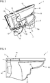
- the Fig. 1-5 each show a schematic diagram of a sanitary device 1 according to an embodiment of the invention. Obviously the show Fig. 1-3 each perspective views and the Fig. 4 . 5 each sectional views of the sanitary device 1. The cutting direction and the viewing direction are in Fig. 1 indicated by the general section line A - A.
- the sanitary device 1 is equipped with a device 2 for the analysis of urine. On the integration of such a device 2 in the sanitary device 1 can be a simple way to perform an analysis or an investigation of issued in the sanitary device 1 urine or other body fluids.
- the sanitary device 1 comprises a floor-standing or wall-mounted WC 3.
- the toilet 3 comprises a ceramic base body 4.
- the base body 4 has various surface portions, of which in the following only the surface portions 4a - 4d are described in more detail. Referring to the properly assembled state of the main body 4, this upper surface portion 4a for mounting a lid and / or seat portion (not shown), inner surface portions 4b, which has an inner bowl-like area in which excretions or body fluids, d. H. in particular faeces and urine, limit, rear surface portions 4 c, via which a connection to a connected to a sewer pipe (not shown) is possible, and front surface portions 4 d.
- the device 2 is in Fig. 1 not visible because it is behind a cover 5 in the form of a ceramic shutter.
- the cover 5 can by suitable fasteners (not shown), z. B. in the form of mounting brackets, in its position and position relative to the toilet-side base 4 are fixed.
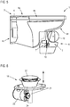
- Fig. 2 . 3 the cover 5 is removed, so that the device 2 can be seen respectively reveal these associated components.
- the Fig. 4-5 show the device 2, respectively one of these associated housing part 6, in or on which the essential components or Function components of the device 2 are received or stored without a corresponding cover 5.
- the essential components or functional components of the device 2 include a supply and discharge device 7, which for supplying a certain amount of urine in a at least one analysis area 8 having analysis chamber 9 of a urine test strip 10 and for discharging a certain amount of urine from one or the at least one analysis area 8 analysis chamber 9 of one or the urine test strip 10 is set up.
- Structure and function of the supply and discharge device 7 are in particular in connection with the Fig. 7 - 10 described in more detail.
- the essential components or functional components of the device 2 further include a detection device 11, which is set up to detect an at least section-wise change of at least one optically detectable parameter of or a corresponding analysis region 8 of the or a urine test strip 10.
- the optically detectable parameter changes in an optically detectable manner depending on the composition of a urine test strip-side analysis area 8 contacting urine amount, ie, for example, by changing the color and / or by changing the color intensity. Sonach is z. B. in the color or the color intensity of the analysis area 8 by a corresponding optically detectable parameter.
- the detection device 11 is further configured to generate detection information which describes at least one such optically detectable or detected parameter of an analysis area 8 or a change thereof.
- the detection device 11 includes optical, detecting means in the form of optical scanners for detecting a corresponding change of an optically detectable parameter.
- the function of the detection device 11 is also particularly in connection with the Fig. 7 - 10 described in more detail.
- a conveyor 12 in the form of a conveyor roller rotatable stored.
- the conveying device 12 is for conveying at least one urine test strip 10 into a detection region defined on the device side, in which detection of an at least section-wise change of a corresponding optically detectable parameter of a urine test strip side analysis region 8 is possible by means of the detection device 11, and / or from such a detection region.
- the conveying device designed as a conveying device 12 or on the conveying roller designed as a conveying device 12 is a particular in connection with Fig. 13 more detailed composite 13 of several band or belt-shaped interconnected urine test strips 10 unrolled or rolled up.
- Fig. 1 further shows a toilet-body-side removal device 14.
- the removal device 14 is disposed within an opening in the region of the inner surface portions 4b of the base body 4.
- the removal device 14 is used in the context of urinating a user in the toilet 3, the removal of a certain amount of urine, which is to be supplied to the device 2 for analysis purposes. Structure and function of the removal device 14 will with reference to Fig. 6 described in more detail.
- a first line section 15a of a feed line 15 leads from the removal device 14 into the device-side feed and discharge device 7 to a tank 16. It is therefore in a leading into the device 2 supply line 15, a tank 16 connected in which a certain amount of urine, z. B. about 200 ml, before the actual feed into the device 2 respectively in the device-side supply and discharge device 7 can be collected and maintained.
- the tank 16 is therefore connected between the removal device 14 and the device-side supply and discharge device 7.
- the tank 16 is equipped with an unspecified ventilation device in the form of a ventilation valve and a fill level detecting means not specified in the form of a level sensor.
- a second line section 15b of the supply line 15 leads into the device-side supply and discharge device 7.
- the first line section 15a of the supply line 15 is z. B. to a flexible fabric hose
- in the second line section 15 b of the supply line 15 is z. B. to a laboratory tube with a smaller compared to the or a hose diameter.
- a derivative 19 in the limited by the inner surface portions 4b of the base body 2 interior of the toilet 3 leads. It is thus possible to return urine back into the WC 3 after the analysis carried out by means of the device 2 and thus supply it to a WC-side outflow.
- the derivative 19 may also be a laboratory hose.
- Fig. 4 shows the toilet-side base body 4 without attached to this housing part 6
- Fig. 5 shows the toilet-side body 4 with attached to this housing part 6.
- the base body 4 is provided with fastening elements 20 in the region of the exposed front surface portions 4d.
- the fasteners 20 are z. B. attached by means of an adhesive bond to the base body 4.
- the fastening elements 20 comprise unspecified, threaded bolt-shaped fastening sections, via which the housing part 6 to these non-positively, ie in particular by means of a screw fastened.
- the housing part 6 corresponding threaded holes or openings for the realization of the attachment, ie in particular the screw on.
- three corresponding fastening elements 20 are provided on the base body side, so that a three-point attachment of the housing part 6 to the base body 4 can be realized.
- Fig. 6 shows a schematic diagram of a removal device 14 of the or a sanitary device 1 according to an embodiment of the invention.
- Removal device 14 shown in a single view comprises a hollow cylindrical pipe element 21 passing through an opening of the base body 4, which is mounted movably between an open and a closed position relative to a disc-shaped closing element 22 permanently mounted on the base body side.
- the mobility of the tubular element 21 between the open and closed positions is in Fig. 6 indicated by the double arrow.
- the tubular element 21 with a funnel-shaped portion which likewise forms the free end of the tubular member 21, so moved away from the closing element 22 that urine flow from the interior of the base body 4 in or through the tubular element 21 and thus in the can reach the extraction device 14 subsequent first line section 15a of the supply line 15 in the supply and discharge device 7.
- a sieve may be present in the connection means or upstream of the connection means.
- the tubular element 21 can be sealingly closed in the closed position by a sealing engagement with the closing element 22. In other words, the tubular element 21 is moved sealingly against the closing element 22 in the closed position.
- the sealing system is by an outer peripheral side of the Closing element 22 arranged unspecified sealing element, z. In the form of an O-ring.
- Movements of the tubular element 21 are realized via a drive device 23 coupled thereto, via which the tubular element 21, in particular between the open and the closed position, is movable.
- the drive device 23 includes z. B. a magnetic drive in the form of a coupled to the tubular element 21 via a pinion or gear member 24 rotary magnet.
- spring means (not shown) may be provided, via which the tubular element 21 can be acted upon by a spring force moving this in the closed position or in the closed position.
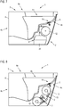
- the Fig. 7 - 10 each show a schematic diagram of a device 2 for the analysis of urine according to an embodiment of the invention.
- the show Fig. 7, 8 respective sectional views of different embodiments of a WC-side attached device 2
- Fig. 9 an enlarged partial view of the device 2 according to the in Fig. 7 shown embodiment
- Fig. 10 an enlarged partial view of a plan view of the device. 2
- the device-side housing part 6 compared to the in Fig. 3 shown representation has a slightly different geometric-spatial shape, which in principle suggests a possible design freedom of the device 1 and the associated components.
- the main difference between those in the Fig. 7, 8 shown different embodiments of the device 2 consists in the number of the conveyor 12 associated conveyor rollers. While at the in Fig. 7 shown embodiment, only one conveyor 12 with a single conveyor roller, from which a corresponding composite 13 of several band or belt-shaped interconnected urine test strip 10 is unrolled, is present at the in Fig. 8 shown embodiment, a conveyor 12 with two conveyor rollers and this upstream or downstream, provided in the embodiment in comparison to the conveyor rollers smaller deflection rollers. Accordingly, it is in the in Fig.
- a composite 13 of a plurality of band strips or belt-shaped urine test strips 10 to be rolled from a first conveyor roller such that at least one urine test strip 10 to be conveyed into the detection area of the detection device 11 is movable or moved into the detection area, and to a second one Conveyor roll can be rolled up so that it is movable or moved out of the detection area.
- a detection device 11 downstream of the separating device 25 is provided (see. Fig. 9 ), which is set up to separate at least one urine test strip 10 from the composite 13 of a plurality of tape or belt-shaped interconnected urine test strips 10.
- the severing device 25 includes z. As an unspecified blade or a laser.
- Fig. 9 is an enlarged view of the in Fig. 7 shown embodiment of the device 2 shown.
- a corresponding composite 13 of urine test strips 10 connected to one another extends between a gap space formed between the detection device 11 and the supply and discharge device 7 and thus through a corresponding detection region the detection device 11.
- the guidance and positioning of the composite 13 is supported by a likewise a part of the conveyor 12 forming, rotatably mounted Noppenrad 26.
- the nub wheel 26 comprises conveying sections formed by circumferentially spaced, radially extending nubs 27 for conveying at least one urine test strip 10. By rotating the nub wheel 26, the urine test strips 10 can be continuously or discontinuously conveyed through the detection area.
- the cannula-like delivery element 28, which is mounted in a linear or translationally movable manner, and a correspondingly movably mounted, cannula-like discharge element 29, comprises the delivery and removal device 7.
- the feed element 28 serves to supply a specific quantity of urine to a feed region 33 of an analysis chamber 9 of a urine test strip
- the discharge element 29 serves to discharge a specific amount of urine from a discharge region 34 of an analysis chamber 9 of a urine test strip 10.
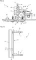
- the supply and discharge device 7 has a drive device 32 coupled thereto.
- the drive device 32 includes an electric motor (not shown).
- the feed or discharge element 28, 29 so against the or a urine test strip side feed region 33 and discharge area 34 movable that a cannula-like tip of the feed or discharge element 28, 29 for supply and / or discharge of a certain Urine amount in or out of the urine test strip side analysis chamber 9 in a urine test strip side inlet and / or Abconstructed Siemens 33, 34 penetrates.
- the movable bearing and thus the axis of movement of the feed element 28 and the discharge element 29 are indicated by the double arrow.
- the drive device 32 via several components, such. B. a gear 30 and a meshing with this rack 31, coupled to the feed and the discharge element 28, 29, so that rotational movements of a Drive device-side output shaft (not shown) via the gear 30 and the rack 31 in translational movements of the feed element 28 and the discharge element 29 can be implemented.
- the device 2 is furthermore equipped with a position determining device 36 which is arranged above the detection device 11 and which is set up for positioning a correct positioning of a urine test strip-side analysis region 8 or detection of a change in such a detection device 11 To determine urine test strip 10.
- a position determining device 36 which is arranged above the detection device 11 and which is set up for positioning a correct positioning of a urine test strip-side analysis region 8 or detection of a change in such a detection device 11 To determine urine test strip 10.
- Another, below the detection device 11 arranged position detecting device 36 is adapted to determine a starting position of the separating device 25.
- the starting position of the separating device 25 is defined by the fact that there is no separation of a urine test strip 10 from the composite 13 in this.
- the position detection devices 36 each include light barriers for the purposes mentioned.
- the device 2 further comprises a in a feed line 28 leading to a feed line 15 connected pumping device 37 and in a leading out of a discharge element 29 derivative 19 pump means 37.
- the pump means 37 in which it is z. B. can be small-sized rotary pumps, serve in particular to urine through the device 2, ie in particular to promote or pump into a corresponding urine test strip side analysis chamber 9 respectively from a corresponding urine test strip side analysis chamber 9 to promote or pump.
- the device 2 is equipped with a pressure determining device 38, which is set up to determine the pressure of a quantity of urine guided into the urine test strip side feed region 33, in particular the pressure of the quantity of urine passed through the feed element 28.
- the Pressure determining device 38 includes suitable pressure sensors for this purpose.
- the pressure detecting device 38 is also in the Fig. 14 ff shown schematically.
- the device 2 further comprises a in the Fig. 14 ff schematically shown bypass line 41, which connects the leading into a feed element 28 feed line 15 and a leading out of a discharge element 29 discharge line 19.
- a valve device 42 for opening and closing the bypass line 41 is connected in the bypass line 41.
- Fig. 10 shows an enlarged partial view of a plan view of the device 2. Based on Fig. 10 is the movable mounting of the feed and discharge device 7 associated feed and discharge element 28, 29 in turn indicated by a double arrow.
- the delivery and discharge elements 28, 29, which are typically driven and moved simultaneously and uniformly, are spaced apart from the urine test strip 10 and a corresponding urine test strip side feed region 33 and a urine test strip side discharge region 34, respectively.
- a supply or discharge of a certain amount of urine into the urine test strip side analysis chamber 9 is only possible when the feed element 28 has penetrated into the urine test strip side feed region 33 and the discharge element 29 into the urine test strip side discharge region 34.
- the urine test strip-side feed region 33, as well as the urine test strip-side discharge region 34 are structurally defined by a dome-shaped or spherical-segment-shaped bulge.
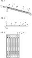
- FIGS Fig. 11 - 13 each of which is a schematic diagram of a urine test strip device 39 according to a Embodiment of the invention, show, described. It shows Fig. 11 a single urine test strip 10 in a perspective view, Fig. 12 a sectional view along the in Fig. 11 shown section lines XII - XII and Fig. 13 a plan view of a composite 13 of several band or belt-shaped interconnected urine test strips 10th
- a single urine test strip 10 typically has a rectangular basic shape.
- An analysis chamber 9 having an analysis area 8 for analysis of urine is located between an upper encapsulation element section 40a and a lower encapsulation element section 40b.
- the upper encapsulation element section 40a and the lower encapsulation element section 40b jointly form an encapsulation element 40, via which the analysis region 8 is encapsulated and thus protected from external influences, ie, in particular from moisture.
- the upper encapsulation element section 40a is embodied as a three-dimensionally complex molded part and has a substantially planar central wall section delimiting the analysis chamber 9 and two dome-shaped or spherical segment-shaped lateral wall sections delimiting the feed section 33 and the discharge section 34. Of course, there is a passage between the supply and discharge region 33, 34 and the analysis chamber 8, which thus communicate with each other.
- the upper encapsulation member portion 40 a is made of a transparent plastic material, such. As PC, formed.
- the plastic material is so transparent that it can detect a change in an optically detectable parameter of the analysis area 8, i. H. z. B. a color change, by means of the detection device 11 permits.
- the lower encapsulation element section 40b is not shaped in a complex three-dimensional manner, but is formed in a flat or foil-like manner.
- the lower encapsulation element section 40b lies correspondingly as a surface part or as a foil in front. Its thickness is typically in a range between 30 and 120 .mu.m, in particular in a range between 70 and 110 .mu.m.
- the lower encapsulation element 40b is made of a resilient plastic material, such. B. PE and / or PET, or a plastic composite material. With regard to the elastic properties, the lower encapsulation element section 40b can also be made of a thermoplastic elastomer, i. H. z. As TPO and / or TPV be formed.
- the elastic properties of the lower encapsulation element section 40b make it possible for a perforating feed or discharge element 28, 29 penetrating into the feed or discharge region 33, 34 to be sealingly enclosable in sections.
- the lower encapsulation element section 40b thus conforms to a feed or discharge element 28, 29 which penetrates into the feed or discharge region 33, 34, so that it is ensured that during the supply or removal of a certain amount of urine in the or from the urine test strip 10 no leakage occurs.
- the elastic properties of the lower encapsulation element section 40b likewise make it possible for a perforated region to be sealed by the limiting material sections.
- the lower encapsulation element section 40b therefore also serves as a septum or as a closure membrane, which ensures that no leakage occurs even after the supply or removal of a specific amount of urine from the urine test strip 10.
- Fig. 13 shows a composite 13 multiple urine test strips 10.
- the urine test strips 10 are connected to each other band or belt-shaped.
- the composite 13 may therefore be referred to or considered as having a plurality of urine test strips 10 having tape or multiple urine test strips 10 having belt.
- the urine test strips 10 are connected to one another in the region of their respective longitudinal sides.
- the connection between corresponding urine test strips 10 is formed in particular via respective encapsulation elements 40, which under Formation of continuous or discontinuous connection areas are connected to each other at least in sections.
- the encapsulation elements 40 each adjacent arranged urine test strips 10 may be z. B. glued or welded.
- FIG. 14 - 19 which each show a schematic representation of different operating modes of a sanitary device 1 according to an embodiment of the invention, different embodiments of a method for operating a sanitary device 1 with one of these associated device 2 are described below.
- the description of the operating modes is based on one as described above, and in the Fig. 14 ff each illustrated configuration of the sanitary device 1 and the device 2. Fluid flows are in the Fig. 14 ff generally indicated by arrows.
- a purging-side pump device is also provided with reference numeral 37.
- Fig. 14 is an exemplary mode of operation for realizing a removal of a certain amount of urine and an analysis of this, ie in particular a detection of a corresponding detection information, shown.
- the amount of urine removed via the removal device 14 is conveyed or pumped by means of the pump devices 37 via the supply line 15 into the urine test strip 10, ie via the analysis region 8 and thus through the analysis chamber 9.
- the amount of urine is subsequently conveyed or pumped via the discharge line 19 from the urine test strip 10 and from the device 2, ie in particular after the analysis and generation of the detection information.
- corresponding device-side feed elements 28 and discharge elements 29 have previously penetrated into corresponding urine test strip-side feed or discharge regions 33, 34.
- the switched into the bypass line 41 valve device 42 is closed here.
- the detection device 11 generates a corresponding detection information, which, as will be described below, in particular to an integrated into the device 2 or to an external, ie spatially separated to the device 2, evaluation device (not shown) is transmitted.
- Fig. 15 For example, an exemplary mode of operation for implementing emptying of the supply line 15 and the discharge line 19 is shown.
- the switched into the bypass line 41 valve device 42 is opened in this case, so that in the supply line 15 and the discharge 19 optionally existing Urinmengenreste can be pumped out.
- Fig. 16 is an exemplary mode of operation for the realization of a flushing of the supply line 15 as well as the removal device 14 upstream of this shown.
- flushing fluid in particular water
- the valve devices 18 as well as the valve device 42 connected in the bypass line 41 are in this case connected in such a way that inflow of the flushing fluid into the supply and discharge device 7 or into the discharge line 19 is not possible.
- Fig. 17 is an exemplary operating mode for the realization of a rinsing of the supply line 15 subsequent emptying of the supply line 15 as well as the removal device 14 upstream of this shown.
- the emptying of the supply line 15 as well as the removal device 14 takes place by opening the valve device 42 connected in the bypass line 41, so that flushing fluid residues can be conveyed or pumped via the discharge line 19 out of the supply line 15 and the removal device 14.
- Fig. 18 an exemplary operating mode for realizing rinsing of the supply and discharge device 7 and a urine test strip 10 is shown.
- flushing fluid in particular water
- the valve devices 18 as well as in the bypass line 41st switched valve device 42 are in this case connected such that an influx of the flushing fluid into the supply line 15 is not possible.
- FIG. 19 an exemplary operating mode for realizing a flushing of the discharge 19, which can follow the rinsing of the supply and discharge device 7 and the urine test strip 10.
- rinsing fluid in particular water
- the valve devices 18 as well as the valve device 42 connected in the bypass line 41 are in this case connected such that inflow of the flushing fluid into the supply line 15 or into the supply and discharge device 7 is not possible.
- a central control device (not shown).
- the control device communicates for this purpose in particular with all device-side devices.
- the control device is typically at least one control provision deposited, according to which a concerted, d. H. coordinated control of the operation of the supply and discharge device 7, the detection device 11 and other devices 2 of the associated devices is possible.
- the latter include, in particular, corresponding pressure-determining devices 38, pump devices 37 and the valve devices 18, 42.
- the detection device 11 is typically designed for communication with at least one evaluation device which is set up for the purpose of evaluating detection information generated by the detection device and for determining evaluation information describing an analysis of the amount of urine present on the analysis region of the urine test strip.
- the evaluation device may be part of the device 2 or externally be.
- the device 2 comprises a transmitting and / or receiving device (not shown) associated with the detection device 11, which enables a wired or wireless transmission of corresponding detection information.
- the sanitary device 1 and the device 2 is accordingly, z. B. by means of Bluetooth, WLAN, etc., to a local or global data network, ie, for example, to a local intranet or the Internet, connected or involved in such. Accordingly, detection information can be transmitted to corresponding evaluation devices, in which conclusions can be drawn on the proportionate or chemical composition of the amount of urine applied to the analysis area on the basis of the detection information.
Landscapes
- Health & Medical Sciences (AREA)
- Life Sciences & Earth Sciences (AREA)
- Engineering & Computer Science (AREA)
- Biomedical Technology (AREA)
- Chemical & Material Sciences (AREA)
- General Health & Medical Sciences (AREA)
- Pathology (AREA)
- Physics & Mathematics (AREA)
- Urology & Nephrology (AREA)
- Molecular Biology (AREA)
- Hematology (AREA)
- Immunology (AREA)
- Analytical Chemistry (AREA)
- Biochemistry (AREA)
- General Physics & Mathematics (AREA)
- Medical Informatics (AREA)
- Biophysics (AREA)
- Veterinary Medicine (AREA)
- Public Health (AREA)
- Animal Behavior & Ethology (AREA)
- Surgery (AREA)
- Heart & Thoracic Surgery (AREA)
- Food Science & Technology (AREA)
- Medicinal Chemistry (AREA)
- Dispersion Chemistry (AREA)
- Physiology (AREA)
- Investigating Or Analysing Biological Materials (AREA)
- Sampling And Sample Adjustment (AREA)
Priority Applications (3)
| Application Number | Priority Date | Filing Date | Title |
|---|---|---|---|
| DK18169356.5T DK3373003T3 (en) | 2014-10-31 | 2015-10-05 | Urinteststrimmel |
| PL18169356T PL3373003T3 (pl) | 2014-10-31 | 2015-10-05 | Pasek do badania moczu |
| EP18169356.5A EP3373003B1 (de) | 2014-10-31 | 2015-10-05 | Urinteststreifen |
Applications Claiming Priority (2)
| Application Number | Priority Date | Filing Date | Title |
|---|---|---|---|
| DE102014115914.4A DE102014115914A1 (de) | 2014-10-31 | 2014-10-31 | Vorrichtung zur Analyse von Urin |
| PCT/EP2015/072908 WO2016066372A1 (de) | 2014-10-31 | 2015-10-05 | Vorrichtung zur analyse von urin |
Related Child Applications (2)
| Application Number | Title | Priority Date | Filing Date |
|---|---|---|---|
| EP18169356.5A Division EP3373003B1 (de) | 2014-10-31 | 2015-10-05 | Urinteststreifen |
| EP18169356.5A Division-Into EP3373003B1 (de) | 2014-10-31 | 2015-10-05 | Urinteststreifen |
Publications (2)
| Publication Number | Publication Date |
|---|---|
| EP3213069A1 EP3213069A1 (de) | 2017-09-06 |
| EP3213069B1 true EP3213069B1 (de) | 2018-12-12 |
Family
ID=54256745
Family Applications (2)
| Application Number | Title | Priority Date | Filing Date |
|---|---|---|---|
| EP15775435.9A Active EP3213069B1 (de) | 2014-10-31 | 2015-10-05 | Vorrichtung zur analyse von urin |
| EP18169356.5A Active EP3373003B1 (de) | 2014-10-31 | 2015-10-05 | Urinteststreifen |
Family Applications After (1)
| Application Number | Title | Priority Date | Filing Date |
|---|---|---|---|
| EP18169356.5A Active EP3373003B1 (de) | 2014-10-31 | 2015-10-05 | Urinteststreifen |
Country Status (13)
| Country | Link |
|---|---|
| US (1) | US10605717B2 (es) |
| EP (2) | EP3213069B1 (es) |
| CN (1) | CN107110845B (es) |
| DE (1) | DE102014115914A1 (es) |
| DK (1) | DK3373003T3 (es) |
| ES (2) | ES2718754T3 (es) |
| HR (1) | HRP20220430T1 (es) |
| HU (1) | HUE058074T2 (es) |
| PL (1) | PL3373003T3 (es) |
| PT (1) | PT3373003T (es) |
| SI (1) | SI3373003T1 (es) |
| SM (1) | SMT202200161T1 (es) |
| WO (1) | WO2016066372A1 (es) |
Families Citing this family (32)
| Publication number | Priority date | Publication date | Assignee | Title |
|---|---|---|---|---|
| EP3331445B1 (en) * | 2015-08-05 | 2019-10-23 | ART Healthcare Ltd. | Point of care urine analyzer |
| US20180059129A1 (en) * | 2016-08-25 | 2018-03-01 | Rajan Dewar | Automated urinalysis |
| KR101772174B1 (ko) * | 2016-09-12 | 2017-08-28 | 주식회사 프로텍엘앤에이치 | 휴대용 소변 분석 장치 |
| US11224370B2 (en) * | 2017-01-24 | 2022-01-18 | Hall Labs Llc | In-toilet urinalysis system with capillary dispenser |
| EP3641644A4 (en) * | 2017-06-23 | 2021-07-28 | Voyant Diagnostics, Inc. | MEDICAL DIAGNOSIS SYSTEM AND METHOD |
| WO2019016197A1 (en) * | 2017-07-21 | 2019-01-24 | Koninklijke Philips N.V. | URINE ANALYSIS SYSTEM |
| US10921310B2 (en) * | 2017-07-27 | 2021-02-16 | Asghar D. Mostafa | Bio-fluid analysis and reporting system and method |
| DE102017010119A1 (de) | 2017-11-02 | 2019-05-02 | Duravit Aktiengesellschaft | Analyseeinrichtung für Körperflüssigkeiten, Analysenset, Verfahren zur Analyse von Körperflüssigkeiten unter Verwendung der Analyseeinrichtung sowie Verfahren zur Analyse von Körperflüssigkeiten unter Verwendung des Analysensets |
| DE102017010120B4 (de) | 2017-11-02 | 2021-04-01 | Duravit Aktiengesellschaft | Reagenzträger zur Bestimmung von Analyten in flüssigen Proben, Analyseeinrichtung und Analyseset zur Bestimmung von Analyten in Urin sowie Analyseverfahren unter Verwendung des Reagenzträgers |
| DE102017011883A1 (de) * | 2017-11-14 | 2019-05-16 | Medipee Gmbh | Vorrichtung zur Vor-Ort-Analyse von Exkrementen, Verfahren zum Betreiben einer derartigen Vorrichtung und Anordnung bestehend aus einer Toilette und einer derartigen Vorrichtung |
| CN107976440B (zh) * | 2018-01-05 | 2023-11-07 | 九牧厨卫股份有限公司 | 一种尿检马桶及尿检方法、清洗方法 |
| WO2020140003A1 (en) * | 2018-12-27 | 2020-07-02 | Hall Labs, Llc | Liquid sample capture apparatus |
| CN110085311A (zh) * | 2019-04-25 | 2019-08-02 | 袁久洪 | 一种便携式排尿监测与预警系统及方法 |
| WO2020221943A1 (es) * | 2019-04-29 | 2020-11-05 | S-There Technologies, S.L. | Dispositivo de análisis de orina para la monitorizacion de la salud y procedimiento relacionado |
| US20200390422A1 (en) * | 2019-06-17 | 2020-12-17 | Medic, Inc. | Toilet for Analysis of Settled Urine |
| US11747239B2 (en) * | 2019-06-17 | 2023-09-05 | Hall Labs Llc | Toilet with digitally controlled manifold to distribute fluids |
| WO2021141561A1 (en) * | 2020-01-06 | 2021-07-15 | Sayden Serbest Muhasebeci Mali Musavirlik Limited Sirketi | Universal toilet bowl/urinal-like uroflowmetry system measuring with real-time volume increase principle |
| JP7482648B2 (ja) | 2020-02-28 | 2024-05-14 | 株式会社Lixil | 便器装置 |
| FR3107824B1 (fr) | 2020-03-03 | 2025-02-14 | Withings | Dispositif et méthode d’analyse d’urine |
| FR3107823B1 (fr) | 2020-03-03 | 2025-02-14 | Withings | Dispositif et méthode d’analyse d’urine |
| CN112129749A (zh) * | 2020-07-11 | 2020-12-25 | 海南蓝瑞科技有限公司 | 一种用于马桶的尿液自动检测装置 |
| EP4168800A4 (en) * | 2020-07-16 | 2024-07-24 | Oruba Medikal Teknoloji Arge Ic Ve Dis Tic. Ltd. Sti | URINE SAMPLE ANALYSIS SYSTEM |
| US12575814B2 (en) | 2021-03-26 | 2026-03-17 | C. R. Bard, Inc. | Fluid sample collection system |
| US20220404333A1 (en) * | 2021-06-22 | 2022-12-22 | C. R. Bard, Inc. | In-Line Urinalysis System and Method |
| FR3126613A1 (fr) | 2021-09-08 | 2023-03-10 | Withings | Station pour dispositif d’analyse d’urine, dispositif d’analyse d’urine, méthodes associées |
| FR3126612A1 (fr) | 2021-09-08 | 2023-03-10 | Withings | Station pour dispositif d’analyse d’urine, dispositif d’analyse d’urine, méthodes associées |
| FR3126611A1 (fr) | 2021-09-08 | 2023-03-10 | Withings | Station pour dispositif d’analyse d’urine, dispositif d’analyse d’urine, méthodes associées |
| FR3126614A1 (fr) | 2021-09-08 | 2023-03-10 | Withings | Station pour dispositif d’analyse d’urine, dispositif d’analyse d’urine, méthodes associées |
| CN114382147B (zh) * | 2021-12-29 | 2024-02-23 | 江苏重明鸟厕所人文科技股份有限公司 | 智能马桶的防尿液渗入结构 |
| DE102022206222A1 (de) | 2022-06-22 | 2023-12-28 | Robert Bosch Gesellschaft mit beschränkter Haftung | Reagenzkammer und Verfahren zu ihrer Herstellung sowie mikrofluidische Kartusche |
| EP4386382A1 (en) * | 2022-12-15 | 2024-06-19 | Stichting IMEC Nederland | Device, system and method for automated urine analysis |
| US20250120633A1 (en) * | 2023-10-11 | 2025-04-17 | Hong Min Kim | System for detecting physical properties of urine, urination, and faeces for determination of health concerns |
Family Cites Families (31)
| Publication number | Priority date | Publication date | Assignee | Title |
|---|---|---|---|---|
| CA891208A (en) * | 1968-02-02 | 1972-01-25 | Rogers Riedel | Toilet and sewage treatment apparatus |
| CA1324415C (en) * | 1987-01-27 | 1993-11-16 | Takao Ikenaga | Toilet device with health examination system |
| US4982741A (en) * | 1987-05-22 | 1991-01-08 | Inax Corporation | Apparatus for detecting certain substances in urine, a toilet stool and a system for collecting information on health |
| US4943416A (en) * | 1987-09-23 | 1990-07-24 | Kabushiki Kaisha Marukomu | Automatic urinalysis system |
| US5073500A (en) * | 1988-01-08 | 1991-12-17 | Inax Corporation | Method and apparatus for detecting urinary constituents |
| US5087556A (en) * | 1989-05-17 | 1992-02-11 | Actimed Laboratories, Inc. | Method for quantitative analysis of body fluid constituents |
| ATE135111T1 (de) * | 1989-08-25 | 1996-03-15 | Toto Ltd | Toilette mit einem system zur inspektion des gesundheitszustandes |
| US5208163A (en) * | 1990-08-06 | 1993-05-04 | Miles Inc. | Self-metering fluid analysis device |
| CA2049589A1 (en) * | 1990-08-24 | 1992-02-25 | Naoki Tsukamura | Stool-type apparatus for sampling and assay of urine with swingable carriage |
| US5271895A (en) | 1991-02-27 | 1993-12-21 | Boehringer Mannheim Corporation | Test strip |
| TW290453B (es) * | 1993-12-30 | 1996-11-11 | Toto Ltd | |
| CN1187598C (zh) * | 1994-03-04 | 2005-02-02 | 株式会社京都第一科学 | 同时定量分析尿中数种成分的测定装置 |
| JP3368985B2 (ja) * | 1994-05-10 | 2003-01-20 | バイエルコーポレーション | 自動供給装置 |
| JPH0815133A (ja) * | 1994-06-29 | 1996-01-19 | Hitachi Ltd | 分析素子 |
| DK1031036T3 (da) * | 1997-10-06 | 2008-09-15 | Enterix Inc | Apparat og fremgangsmåde til detektion af et analysemateriale |
| US6403298B1 (en) * | 1998-06-16 | 2002-06-11 | All Technologies Corporation | Method and apparatus for urine self-test intended for use in a toilet |
| US6375897B1 (en) * | 2000-02-14 | 2002-04-23 | Ansys Technologies, Inc. | Urine collection cup |
| ATE336718T1 (de) * | 2002-04-03 | 2006-09-15 | Univ Jw Goethe Frankfurt Main | Infrarotmessvorrichtung für die spektrometrie wässriger und nicht wässriger systeme |
| US7148070B2 (en) * | 2003-01-24 | 2006-12-12 | Minter Jimmy C | Diagnostic detection method |
| JP2006521555A (ja) * | 2003-03-24 | 2006-09-21 | ローズデイル メディカル インコーポレイテッド | 被分析物濃度検出の装置及び方法 |
| JP4840940B2 (ja) * | 2004-12-13 | 2011-12-21 | バイエル・ヘルスケア・エルエルシー | 自蔵型検査センサ |
| JPWO2007072990A1 (ja) * | 2005-12-21 | 2009-06-04 | シチズンホールディングス株式会社 | カセット及び測定装置 |
| US8012762B2 (en) * | 2007-04-17 | 2011-09-06 | Steve Lee | Test device, and related methods |
| GB2456079B (en) * | 2007-08-17 | 2010-07-14 | Diagnostics For The Real World | Device, system and method for processing a sample |
| KR100972622B1 (ko) * | 2008-06-30 | 2010-07-28 | 주식회사 메카시스 | 소변 검사장치 |
| KR101159273B1 (ko) * | 2010-12-03 | 2012-06-25 | 주식회사 메카시스 | 스트립 수납부재 및 이를 포함하는 소변검사장치 |
| DE102010061035B4 (de) * | 2010-12-06 | 2012-10-31 | BITS Zwickau Büromat IT-Systeme GmbH | Intelligente Toilette und Verfahren zu deren Betrieb |
| KR101080832B1 (ko) * | 2011-01-31 | 2011-11-07 | 전인수 | 변좌 내장식 소변 분석 시스템 |
| JP5267617B2 (ja) | 2011-06-23 | 2013-08-21 | ウシオ電機株式会社 | 分析装置および分析方法 |
| CN202745164U (zh) * | 2012-07-24 | 2013-02-20 | 叶代红 | 一种家用智能健康检查坐便器 |
| CN102877526B (zh) * | 2012-10-08 | 2013-12-11 | 镡丰锦 | 自动蓄尿干化学分析尿检座便器 |
-
2014
- 2014-10-31 DE DE102014115914.4A patent/DE102014115914A1/de not_active Withdrawn
-
2015
- 2015-10-05 HR HRP20220430TT patent/HRP20220430T1/hr unknown
- 2015-10-05 PL PL18169356T patent/PL3373003T3/pl unknown
- 2015-10-05 ES ES15775435T patent/ES2718754T3/es active Active
- 2015-10-05 SI SI201531819T patent/SI3373003T1/sl unknown
- 2015-10-05 EP EP15775435.9A patent/EP3213069B1/de active Active
- 2015-10-05 SM SM20220161T patent/SMT202200161T1/it unknown
- 2015-10-05 DK DK18169356.5T patent/DK3373003T3/da active
- 2015-10-05 HU HUE18169356A patent/HUE058074T2/hu unknown
- 2015-10-05 WO PCT/EP2015/072908 patent/WO2016066372A1/de not_active Ceased
- 2015-10-05 EP EP18169356.5A patent/EP3373003B1/de active Active
- 2015-10-05 CN CN201580058959.3A patent/CN107110845B/zh active Active
- 2015-10-05 ES ES18169356T patent/ES2909079T3/es active Active
- 2015-10-05 US US15/518,132 patent/US10605717B2/en active Active
- 2015-10-05 PT PT181693565T patent/PT3373003T/pt unknown
Non-Patent Citations (1)
| Title |
|---|
| None * |
Also Published As
| Publication number | Publication date |
|---|---|
| SI3373003T1 (sl) | 2022-05-31 |
| DE102014115914A1 (de) | 2016-05-04 |
| CN107110845B (zh) | 2020-03-27 |
| WO2016066372A1 (de) | 2016-05-06 |
| EP3373003B1 (de) | 2022-02-09 |
| EP3373003A1 (de) | 2018-09-12 |
| EP3213069A1 (de) | 2017-09-06 |
| HRP20220430T1 (hr) | 2022-05-27 |
| ES2909079T3 (es) | 2022-05-05 |
| PT3373003T (pt) | 2022-04-04 |
| US20170284925A1 (en) | 2017-10-05 |
| US10605717B2 (en) | 2020-03-31 |
| SMT202200161T1 (it) | 2022-05-12 |
| CN107110845A (zh) | 2017-08-29 |
| HUE058074T2 (hu) | 2022-06-28 |
| ES2718754T3 (es) | 2019-07-04 |
| DK3373003T3 (en) | 2022-04-04 |
| PL3373003T3 (pl) | 2022-06-20 |
Similar Documents
| Publication | Publication Date | Title |
|---|---|---|
| EP3213069B1 (de) | Vorrichtung zur analyse von urin | |
| EP1789192B1 (de) | Analytisches testelement | |
| DE102009046637B4 (de) | Sondeneinrichtung zum Messen einer Messgröße eines in einem Prozessbehälter enthaltenen Fluids, insbesondere für sterile Anwendungen | |
| EP1495808B1 (de) | Einwegkassette mit integriertem Flüssigkeitsbehälter | |
| EP3709869B1 (de) | Vorrichtung zur vor-ort-analyse von exkrementen und verfahren zum betreiben einer derartigen vorrichtung | |
| DE112020001692T5 (de) | Rühr-entgasungsvorrichtung | |
| EP1680022A1 (de) | Vorrichtung und verfahren zur probenahme und analyse von körperflüssigkeiten | |
| DE212006000063U1 (de) | Vorrichtung zur Erfassung von Analyten in flüssigen Proben | |
| DE102011005957A1 (de) | System zu Behandlung von Flüssigkeiten | |
| EP1838239A1 (de) | Testeinheit für einmaluntersuchungen einer körperflüssigkeit | |
| DE102010030489A1 (de) | System zu Behandlung von Flüssigkeiten | |
| DE102015101106B4 (de) | Mikrofluidikvorrichtung und Verfahren zur Flussbeeinflussung einer Flüssigkeit in einer Mikrofluidikvorrichtung | |
| DE102012102256B4 (de) | Analysegerät mit Basismodul und austauschbarer Kassette | |
| AT511739B1 (de) | Behältereinheit für eine im wesentlichen flüssige probe | |
| AT520515A1 (de) | Vorrichtung zur Erfassung der Qualität einer Flüssigkeit in einem Versorgungsrohr | |
| DE102008039117B3 (de) | Anordnung und Verfahren zum Erzeugen, Manipulieren und Analysieren von Kompartimenten | |
| EP1914547A1 (de) | Vorrichtung, Messgerät und Verfahren zur Handhabung mikrofluidischer Plattformen | |
| EP2030567A1 (de) | Analysegerät zur Bestimmung eines Analyten in einer Körperflüssigkeit, Magazin für ein Analysegerät und Verfahren zur Erzeugung einer Wunde und zum Untersuchen einer austretenden Körperflüssigkeit | |
| DE102013015106A1 (de) | Sonden-Anschlussvorrichtung, damit ausgestattete Bioreaktor-Anordnung und zugehöriges Montageverfahren | |
| WO2015106872A1 (de) | Brennstoffzellensystem mit einem in einem gehäuse integrierten brennstoffzellenstack | |
| DE102015003745A1 (de) | Mobile Prüfvorrichting, Gasmessgerät und System zum Prüfen eines Gasmessgeräts | |
| DE212016000289U1 (de) | Filtrationsvorrichtung und Filtrationssystem | |
| DE10330803B4 (de) | Einwegkassette und deren Verwendung | |
| WO2013182491A1 (de) | Testsystem zum portionieren, mischen und verteilen von biologischen probenflüssigkeiten | |
| DE10349578A1 (de) | Milchprobenentnahme aus einem Milchsammelbehälter |
Legal Events
| Date | Code | Title | Description |
|---|---|---|---|
| STAA | Information on the status of an ep patent application or granted ep patent |
Free format text: STATUS: THE INTERNATIONAL PUBLICATION HAS BEEN MADE |
|
| PUAI | Public reference made under article 153(3) epc to a published international application that has entered the european phase |
Free format text: ORIGINAL CODE: 0009012 |
|
| STAA | Information on the status of an ep patent application or granted ep patent |
Free format text: STATUS: REQUEST FOR EXAMINATION WAS MADE |
|
| 17P | Request for examination filed |
Effective date: 20170511 |
|
| AK | Designated contracting states |
Kind code of ref document: A1 Designated state(s): AL AT BE BG CH CY CZ DE DK EE ES FI FR GB GR HR HU IE IS IT LI LT LU LV MC MK MT NL NO PL PT RO RS SE SI SK SM TR |
|
| AX | Request for extension of the european patent |
Extension state: BA ME |
|
| DAV | Request for validation of the european patent (deleted) | ||
| DAX | Request for extension of the european patent (deleted) | ||
| STAA | Information on the status of an ep patent application or granted ep patent |
Free format text: STATUS: EXAMINATION IS IN PROGRESS |
|
| 17Q | First examination report despatched |
Effective date: 20180322 |
|
| RIC1 | Information provided on ipc code assigned before grant |
Ipc: A61B 10/00 20060101ALI20180705BHEP Ipc: E03D 11/02 20060101ALI20180705BHEP Ipc: G01N 33/493 20060101AFI20180705BHEP |
|
| GRAP | Despatch of communication of intention to grant a patent |
Free format text: ORIGINAL CODE: EPIDOSNIGR1 |
|
| STAA | Information on the status of an ep patent application or granted ep patent |
Free format text: STATUS: GRANT OF PATENT IS INTENDED |
|
| INTG | Intention to grant announced |
Effective date: 20180810 |
|
| GRAS | Grant fee paid |
Free format text: ORIGINAL CODE: EPIDOSNIGR3 |
|
| GRAA | (expected) grant |
Free format text: ORIGINAL CODE: 0009210 |
|
| STAA | Information on the status of an ep patent application or granted ep patent |
Free format text: STATUS: THE PATENT HAS BEEN GRANTED |
|
| AK | Designated contracting states |
Kind code of ref document: B1 Designated state(s): AL AT BE BG CH CY CZ DE DK EE ES FI FR GB GR HR HU IE IS IT LI LT LU LV MC MK MT NL NO PL PT RO RS SE SI SK SM TR |
|
| REG | Reference to a national code |
Ref country code: GB Ref legal event code: FG4D Free format text: NOT ENGLISH |
|
| REG | Reference to a national code |
Ref country code: CH Ref legal event code: EP |
|
| REG | Reference to a national code |
Ref country code: AT Ref legal event code: REF Ref document number: 1076700 Country of ref document: AT Kind code of ref document: T Effective date: 20181215 |
|
| REG | Reference to a national code |
Ref country code: DE Ref legal event code: R096 Ref document number: 502015007233 Country of ref document: DE |
|
| REG | Reference to a national code |
Ref country code: IE Ref legal event code: FG4D Free format text: LANGUAGE OF EP DOCUMENT: GERMAN |
|
| REG | Reference to a national code |
Ref country code: NL Ref legal event code: FP |
|
| REG | Reference to a national code |
Ref country code: LT Ref legal event code: MG4D |
|
| PG25 | Lapsed in a contracting state [announced via postgrant information from national office to epo] |
Ref country code: FI Free format text: LAPSE BECAUSE OF FAILURE TO SUBMIT A TRANSLATION OF THE DESCRIPTION OR TO PAY THE FEE WITHIN THE PRESCRIBED TIME-LIMIT Effective date: 20181212 Ref country code: BG Free format text: LAPSE BECAUSE OF FAILURE TO SUBMIT A TRANSLATION OF THE DESCRIPTION OR TO PAY THE FEE WITHIN THE PRESCRIBED TIME-LIMIT Effective date: 20190312 Ref country code: LV Free format text: LAPSE BECAUSE OF FAILURE TO SUBMIT A TRANSLATION OF THE DESCRIPTION OR TO PAY THE FEE WITHIN THE PRESCRIBED TIME-LIMIT Effective date: 20181212 Ref country code: HR Free format text: LAPSE BECAUSE OF FAILURE TO SUBMIT A TRANSLATION OF THE DESCRIPTION OR TO PAY THE FEE WITHIN THE PRESCRIBED TIME-LIMIT Effective date: 20181212 Ref country code: NO Free format text: LAPSE BECAUSE OF FAILURE TO SUBMIT A TRANSLATION OF THE DESCRIPTION OR TO PAY THE FEE WITHIN THE PRESCRIBED TIME-LIMIT Effective date: 20190312 Ref country code: LT Free format text: LAPSE BECAUSE OF FAILURE TO SUBMIT A TRANSLATION OF THE DESCRIPTION OR TO PAY THE FEE WITHIN THE PRESCRIBED TIME-LIMIT Effective date: 20181212 |
|
| PG25 | Lapsed in a contracting state [announced via postgrant information from national office to epo] |
Ref country code: RS Free format text: LAPSE BECAUSE OF FAILURE TO SUBMIT A TRANSLATION OF THE DESCRIPTION OR TO PAY THE FEE WITHIN THE PRESCRIBED TIME-LIMIT Effective date: 20181212 Ref country code: SE Free format text: LAPSE BECAUSE OF FAILURE TO SUBMIT A TRANSLATION OF THE DESCRIPTION OR TO PAY THE FEE WITHIN THE PRESCRIBED TIME-LIMIT Effective date: 20181212 Ref country code: GR Free format text: LAPSE BECAUSE OF FAILURE TO SUBMIT A TRANSLATION OF THE DESCRIPTION OR TO PAY THE FEE WITHIN THE PRESCRIBED TIME-LIMIT Effective date: 20190313 Ref country code: AL Free format text: LAPSE BECAUSE OF FAILURE TO SUBMIT A TRANSLATION OF THE DESCRIPTION OR TO PAY THE FEE WITHIN THE PRESCRIBED TIME-LIMIT Effective date: 20181212 |
|
| REG | Reference to a national code |
Ref country code: ES Ref legal event code: FG2A Ref document number: 2718754 Country of ref document: ES Kind code of ref document: T3 Effective date: 20190704 |
|
| PG25 | Lapsed in a contracting state [announced via postgrant information from national office to epo] |
Ref country code: PL Free format text: LAPSE BECAUSE OF FAILURE TO SUBMIT A TRANSLATION OF THE DESCRIPTION OR TO PAY THE FEE WITHIN THE PRESCRIBED TIME-LIMIT Effective date: 20181212 Ref country code: PT Free format text: LAPSE BECAUSE OF FAILURE TO SUBMIT A TRANSLATION OF THE DESCRIPTION OR TO PAY THE FEE WITHIN THE PRESCRIBED TIME-LIMIT Effective date: 20190412 Ref country code: CZ Free format text: LAPSE BECAUSE OF FAILURE TO SUBMIT A TRANSLATION OF THE DESCRIPTION OR TO PAY THE FEE WITHIN THE PRESCRIBED TIME-LIMIT Effective date: 20181212 |
|
| PG25 | Lapsed in a contracting state [announced via postgrant information from national office to epo] |
Ref country code: EE Free format text: LAPSE BECAUSE OF FAILURE TO SUBMIT A TRANSLATION OF THE DESCRIPTION OR TO PAY THE FEE WITHIN THE PRESCRIBED TIME-LIMIT Effective date: 20181212 Ref country code: SM Free format text: LAPSE BECAUSE OF FAILURE TO SUBMIT A TRANSLATION OF THE DESCRIPTION OR TO PAY THE FEE WITHIN THE PRESCRIBED TIME-LIMIT Effective date: 20181212 Ref country code: RO Free format text: LAPSE BECAUSE OF FAILURE TO SUBMIT A TRANSLATION OF THE DESCRIPTION OR TO PAY THE FEE WITHIN THE PRESCRIBED TIME-LIMIT Effective date: 20181212 Ref country code: SK Free format text: LAPSE BECAUSE OF FAILURE TO SUBMIT A TRANSLATION OF THE DESCRIPTION OR TO PAY THE FEE WITHIN THE PRESCRIBED TIME-LIMIT Effective date: 20181212 Ref country code: IS Free format text: LAPSE BECAUSE OF FAILURE TO SUBMIT A TRANSLATION OF THE DESCRIPTION OR TO PAY THE FEE WITHIN THE PRESCRIBED TIME-LIMIT Effective date: 20190412 |
|
| REG | Reference to a national code |
Ref country code: DE Ref legal event code: R097 Ref document number: 502015007233 Country of ref document: DE |
|
| PLBE | No opposition filed within time limit |
Free format text: ORIGINAL CODE: 0009261 |
|
| STAA | Information on the status of an ep patent application or granted ep patent |
Free format text: STATUS: NO OPPOSITION FILED WITHIN TIME LIMIT |
|
| PG25 | Lapsed in a contracting state [announced via postgrant information from national office to epo] |
Ref country code: DK Free format text: LAPSE BECAUSE OF FAILURE TO SUBMIT A TRANSLATION OF THE DESCRIPTION OR TO PAY THE FEE WITHIN THE PRESCRIBED TIME-LIMIT Effective date: 20181212 Ref country code: SI Free format text: LAPSE BECAUSE OF FAILURE TO SUBMIT A TRANSLATION OF THE DESCRIPTION OR TO PAY THE FEE WITHIN THE PRESCRIBED TIME-LIMIT Effective date: 20181212 |
|
| 26N | No opposition filed |
Effective date: 20190913 |
|
| PG25 | Lapsed in a contracting state [announced via postgrant information from national office to epo] |
Ref country code: TR Free format text: LAPSE BECAUSE OF FAILURE TO SUBMIT A TRANSLATION OF THE DESCRIPTION OR TO PAY THE FEE WITHIN THE PRESCRIBED TIME-LIMIT Effective date: 20181212 |
|
| PG25 | Lapsed in a contracting state [announced via postgrant information from national office to epo] |
Ref country code: MC Free format text: LAPSE BECAUSE OF FAILURE TO SUBMIT A TRANSLATION OF THE DESCRIPTION OR TO PAY THE FEE WITHIN THE PRESCRIBED TIME-LIMIT Effective date: 20181212 |
|
| PG25 | Lapsed in a contracting state [announced via postgrant information from national office to epo] |
Ref country code: IE Free format text: LAPSE BECAUSE OF NON-PAYMENT OF DUE FEES Effective date: 20191005 |
|
| PG25 | Lapsed in a contracting state [announced via postgrant information from national office to epo] |
Ref country code: CY Free format text: LAPSE BECAUSE OF FAILURE TO SUBMIT A TRANSLATION OF THE DESCRIPTION OR TO PAY THE FEE WITHIN THE PRESCRIBED TIME-LIMIT Effective date: 20181212 |
|
| PG25 | Lapsed in a contracting state [announced via postgrant information from national office to epo] |
Ref country code: MT Free format text: LAPSE BECAUSE OF FAILURE TO SUBMIT A TRANSLATION OF THE DESCRIPTION OR TO PAY THE FEE WITHIN THE PRESCRIBED TIME-LIMIT Effective date: 20181212 Ref country code: HU Free format text: LAPSE BECAUSE OF FAILURE TO SUBMIT A TRANSLATION OF THE DESCRIPTION OR TO PAY THE FEE WITHIN THE PRESCRIBED TIME-LIMIT; INVALID AB INITIO Effective date: 20151005 |
|
| PG25 | Lapsed in a contracting state [announced via postgrant information from national office to epo] |
Ref country code: MK Free format text: LAPSE BECAUSE OF FAILURE TO SUBMIT A TRANSLATION OF THE DESCRIPTION OR TO PAY THE FEE WITHIN THE PRESCRIBED TIME-LIMIT Effective date: 20181212 |
|
| P01 | Opt-out of the competence of the unified patent court (upc) registered |
Effective date: 20230506 |
|
| PGFP | Annual fee paid to national office [announced via postgrant information from national office to epo] |
Ref country code: NL Payment date: 20231023 Year of fee payment: 9 |
|
| PGFP | Annual fee paid to national office [announced via postgrant information from national office to epo] |
Ref country code: LU Payment date: 20231023 Year of fee payment: 9 |
|
| PGFP | Annual fee paid to national office [announced via postgrant information from national office to epo] |
Ref country code: GB Payment date: 20231025 Year of fee payment: 9 |
|
| PGFP | Annual fee paid to national office [announced via postgrant information from national office to epo] |
Ref country code: ES Payment date: 20231117 Year of fee payment: 9 |
|
| PGFP | Annual fee paid to national office [announced via postgrant information from national office to epo] |
Ref country code: IT Payment date: 20231031 Year of fee payment: 9 Ref country code: FR Payment date: 20231023 Year of fee payment: 9 Ref country code: CH Payment date: 20231102 Year of fee payment: 9 Ref country code: AT Payment date: 20231019 Year of fee payment: 9 |
|
| PGFP | Annual fee paid to national office [announced via postgrant information from national office to epo] |
Ref country code: BE Payment date: 20231023 Year of fee payment: 9 |
|
| PGFP | Annual fee paid to national office [announced via postgrant information from national office to epo] |
Ref country code: DE Payment date: 20241014 Year of fee payment: 10 |
|
| REG | Reference to a national code |
Ref country code: CH Ref legal event code: PL |
|
| REG | Reference to a national code |
Ref country code: NL Ref legal event code: MM Effective date: 20241101 |
|
| REG | Reference to a national code |
Ref country code: AT Ref legal event code: MM01 Ref document number: 1076700 Country of ref document: AT Kind code of ref document: T Effective date: 20241005 |
|
| GBPC | Gb: european patent ceased through non-payment of renewal fee |
Effective date: 20241005 |
|
| PG25 | Lapsed in a contracting state [announced via postgrant information from national office to epo] |
Ref country code: GB Free format text: LAPSE BECAUSE OF NON-PAYMENT OF DUE FEES Effective date: 20241005 |
|
| PG25 | Lapsed in a contracting state [announced via postgrant information from national office to epo] |
Ref country code: BE Free format text: LAPSE BECAUSE OF NON-PAYMENT OF DUE FEES Effective date: 20241031 Ref country code: LU Free format text: LAPSE BECAUSE OF NON-PAYMENT OF DUE FEES Effective date: 20241005 Ref country code: NL Free format text: LAPSE BECAUSE OF NON-PAYMENT OF DUE FEES Effective date: 20241101 |
|
| PG25 | Lapsed in a contracting state [announced via postgrant information from national office to epo] |
Ref country code: FR Free format text: LAPSE BECAUSE OF NON-PAYMENT OF DUE FEES Effective date: 20241031 |
|
| PG25 | Lapsed in a contracting state [announced via postgrant information from national office to epo] |
Ref country code: CH Free format text: LAPSE BECAUSE OF NON-PAYMENT OF DUE FEES Effective date: 20241031 |
|
| PG25 | Lapsed in a contracting state [announced via postgrant information from national office to epo] |
Ref country code: AT Free format text: LAPSE BECAUSE OF NON-PAYMENT OF DUE FEES Effective date: 20241005 |
|
| REG | Reference to a national code |
Ref country code: BE Ref legal event code: MM Effective date: 20241031 |
|
| PG25 | Lapsed in a contracting state [announced via postgrant information from national office to epo] |
Ref country code: IT Free format text: LAPSE BECAUSE OF NON-PAYMENT OF DUE FEES Effective date: 20241005 |
|
| REG | Reference to a national code |
Ref country code: ES Ref legal event code: FD2A Effective date: 20251127 |
|
| PG25 | Lapsed in a contracting state [announced via postgrant information from national office to epo] |
Ref country code: ES Free format text: LAPSE BECAUSE OF NON-PAYMENT OF DUE FEES Effective date: 20241006 |