EP3211237B1 - Scroll compressor - Google Patents
Scroll compressor Download PDFInfo
- Publication number
- EP3211237B1 EP3211237B1 EP17154150.1A EP17154150A EP3211237B1 EP 3211237 B1 EP3211237 B1 EP 3211237B1 EP 17154150 A EP17154150 A EP 17154150A EP 3211237 B1 EP3211237 B1 EP 3211237B1
- Authority
- EP
- European Patent Office
- Prior art keywords
- orbiting scroll
- compressor
- casing
- communication
- communication pipe
- Prior art date
- Legal status (The legal status is an assumption and is not a legal conclusion. Google has not performed a legal analysis and makes no representation as to the accuracy of the status listed.)
- Active
Links
Images


Classifications
-
- F—MECHANICAL ENGINEERING; LIGHTING; HEATING; WEAPONS; BLASTING
- F04—POSITIVE - DISPLACEMENT MACHINES FOR LIQUIDS; PUMPS FOR LIQUIDS OR ELASTIC FLUIDS
- F04C—ROTARY-PISTON, OR OSCILLATING-PISTON, POSITIVE-DISPLACEMENT MACHINES FOR LIQUIDS; ROTARY-PISTON, OR OSCILLATING-PISTON, POSITIVE-DISPLACEMENT PUMPS
- F04C18/00—Rotary-piston pumps specially adapted for elastic fluids
- F04C18/02—Rotary-piston pumps specially adapted for elastic fluids of arcuate-engagement type, i.e. with circular translatory movement of co-operating members, each member having the same number of teeth or tooth-equivalents
-
- F—MECHANICAL ENGINEERING; LIGHTING; HEATING; WEAPONS; BLASTING
- F04—POSITIVE - DISPLACEMENT MACHINES FOR LIQUIDS; PUMPS FOR LIQUIDS OR ELASTIC FLUIDS
- F04C—ROTARY-PISTON, OR OSCILLATING-PISTON, POSITIVE-DISPLACEMENT MACHINES FOR LIQUIDS; ROTARY-PISTON, OR OSCILLATING-PISTON, POSITIVE-DISPLACEMENT PUMPS
- F04C28/00—Control of, monitoring of, or safety arrangements for, pumps or pumping installations specially adapted for elastic fluids
- F04C28/24—Control of, monitoring of, or safety arrangements for, pumps or pumping installations specially adapted for elastic fluids characterised by using valves controlling pressure or flow rate, e.g. discharge valves or unloading valves
- F04C28/26—Control of, monitoring of, or safety arrangements for, pumps or pumping installations specially adapted for elastic fluids characterised by using valves controlling pressure or flow rate, e.g. discharge valves or unloading valves using bypass channels
-
- F—MECHANICAL ENGINEERING; LIGHTING; HEATING; WEAPONS; BLASTING
- F04—POSITIVE - DISPLACEMENT MACHINES FOR LIQUIDS; PUMPS FOR LIQUIDS OR ELASTIC FLUIDS
- F04C—ROTARY-PISTON, OR OSCILLATING-PISTON, POSITIVE-DISPLACEMENT MACHINES FOR LIQUIDS; ROTARY-PISTON, OR OSCILLATING-PISTON, POSITIVE-DISPLACEMENT PUMPS
- F04C18/00—Rotary-piston pumps specially adapted for elastic fluids
- F04C18/02—Rotary-piston pumps specially adapted for elastic fluids of arcuate-engagement type, i.e. with circular translatory movement of co-operating members, each member having the same number of teeth or tooth-equivalents
- F04C18/0207—Rotary-piston pumps specially adapted for elastic fluids of arcuate-engagement type, i.e. with circular translatory movement of co-operating members, each member having the same number of teeth or tooth-equivalents both members having co-operating elements in spiral form
- F04C18/0215—Rotary-piston pumps specially adapted for elastic fluids of arcuate-engagement type, i.e. with circular translatory movement of co-operating members, each member having the same number of teeth or tooth-equivalents both members having co-operating elements in spiral form where only one member is moving
-
- F—MECHANICAL ENGINEERING; LIGHTING; HEATING; WEAPONS; BLASTING
- F04—POSITIVE - DISPLACEMENT MACHINES FOR LIQUIDS; PUMPS FOR LIQUIDS OR ELASTIC FLUIDS
- F04C—ROTARY-PISTON, OR OSCILLATING-PISTON, POSITIVE-DISPLACEMENT MACHINES FOR LIQUIDS; ROTARY-PISTON, OR OSCILLATING-PISTON, POSITIVE-DISPLACEMENT PUMPS
- F04C18/00—Rotary-piston pumps specially adapted for elastic fluids
- F04C18/02—Rotary-piston pumps specially adapted for elastic fluids of arcuate-engagement type, i.e. with circular translatory movement of co-operating members, each member having the same number of teeth or tooth-equivalents
- F04C18/0207—Rotary-piston pumps specially adapted for elastic fluids of arcuate-engagement type, i.e. with circular translatory movement of co-operating members, each member having the same number of teeth or tooth-equivalents both members having co-operating elements in spiral form
- F04C18/0246—Details concerning the involute wraps or their base, e.g. geometry
- F04C18/0253—Details concerning the base
- F04C18/0261—Details of the ports, e.g. location, number, geometry
-
- F—MECHANICAL ENGINEERING; LIGHTING; HEATING; WEAPONS; BLASTING
- F04—POSITIVE - DISPLACEMENT MACHINES FOR LIQUIDS; PUMPS FOR LIQUIDS OR ELASTIC FLUIDS
- F04C—ROTARY-PISTON, OR OSCILLATING-PISTON, POSITIVE-DISPLACEMENT MACHINES FOR LIQUIDS; ROTARY-PISTON, OR OSCILLATING-PISTON, POSITIVE-DISPLACEMENT PUMPS
- F04C18/00—Rotary-piston pumps specially adapted for elastic fluids
- F04C18/02—Rotary-piston pumps specially adapted for elastic fluids of arcuate-engagement type, i.e. with circular translatory movement of co-operating members, each member having the same number of teeth or tooth-equivalents
- F04C18/0207—Rotary-piston pumps specially adapted for elastic fluids of arcuate-engagement type, i.e. with circular translatory movement of co-operating members, each member having the same number of teeth or tooth-equivalents both members having co-operating elements in spiral form
- F04C18/0246—Details concerning the involute wraps or their base, e.g. geometry
- F04C18/0269—Details concerning the involute wraps
- F04C18/0292—Ports or channels located in the wrap
-
- F—MECHANICAL ENGINEERING; LIGHTING; HEATING; WEAPONS; BLASTING
- F04—POSITIVE - DISPLACEMENT MACHINES FOR LIQUIDS; PUMPS FOR LIQUIDS OR ELASTIC FLUIDS
- F04C—ROTARY-PISTON, OR OSCILLATING-PISTON, POSITIVE-DISPLACEMENT MACHINES FOR LIQUIDS; ROTARY-PISTON, OR OSCILLATING-PISTON, POSITIVE-DISPLACEMENT PUMPS
- F04C23/00—Combinations of two or more pumps, each being of rotary-piston or oscillating-piston type, specially adapted for elastic fluids; Pumping installations specially adapted for elastic fluids; Multi-stage pumps specially adapted for elastic fluids
- F04C23/008—Hermetic pumps
-
- F—MECHANICAL ENGINEERING; LIGHTING; HEATING; WEAPONS; BLASTING
- F04—POSITIVE - DISPLACEMENT MACHINES FOR LIQUIDS; PUMPS FOR LIQUIDS OR ELASTIC FLUIDS
- F04C—ROTARY-PISTON, OR OSCILLATING-PISTON, POSITIVE-DISPLACEMENT MACHINES FOR LIQUIDS; ROTARY-PISTON, OR OSCILLATING-PISTON, POSITIVE-DISPLACEMENT PUMPS
- F04C27/00—Sealing arrangements in rotary-piston pumps specially adapted for elastic fluids
-
- F—MECHANICAL ENGINEERING; LIGHTING; HEATING; WEAPONS; BLASTING
- F04—POSITIVE - DISPLACEMENT MACHINES FOR LIQUIDS; PUMPS FOR LIQUIDS OR ELASTIC FLUIDS
- F04C—ROTARY-PISTON, OR OSCILLATING-PISTON, POSITIVE-DISPLACEMENT MACHINES FOR LIQUIDS; ROTARY-PISTON, OR OSCILLATING-PISTON, POSITIVE-DISPLACEMENT PUMPS
- F04C28/00—Control of, monitoring of, or safety arrangements for, pumps or pumping installations specially adapted for elastic fluids
- F04C28/10—Control of, monitoring of, or safety arrangements for, pumps or pumping installations specially adapted for elastic fluids characterised by changing the positions of the inlet or outlet openings with respect to the working chamber
-
- F—MECHANICAL ENGINEERING; LIGHTING; HEATING; WEAPONS; BLASTING
- F04—POSITIVE - DISPLACEMENT MACHINES FOR LIQUIDS; PUMPS FOR LIQUIDS OR ELASTIC FLUIDS
- F04C—ROTARY-PISTON, OR OSCILLATING-PISTON, POSITIVE-DISPLACEMENT MACHINES FOR LIQUIDS; ROTARY-PISTON, OR OSCILLATING-PISTON, POSITIVE-DISPLACEMENT PUMPS
- F04C28/00—Control of, monitoring of, or safety arrangements for, pumps or pumping installations specially adapted for elastic fluids
- F04C28/24—Control of, monitoring of, or safety arrangements for, pumps or pumping installations specially adapted for elastic fluids characterised by using valves controlling pressure or flow rate, e.g. discharge valves or unloading valves
-
- F—MECHANICAL ENGINEERING; LIGHTING; HEATING; WEAPONS; BLASTING
- F04—POSITIVE - DISPLACEMENT MACHINES FOR LIQUIDS; PUMPS FOR LIQUIDS OR ELASTIC FLUIDS
- F04C—ROTARY-PISTON, OR OSCILLATING-PISTON, POSITIVE-DISPLACEMENT MACHINES FOR LIQUIDS; ROTARY-PISTON, OR OSCILLATING-PISTON, POSITIVE-DISPLACEMENT PUMPS
- F04C29/00—Component parts, details or accessories of pumps or pumping installations, not provided for in groups F04C18/00 - F04C28/00
- F04C29/12—Arrangements for admission or discharge of the working fluid, e.g. constructional features of the inlet or outlet
- F04C29/124—Arrangements for admission or discharge of the working fluid, e.g. constructional features of the inlet or outlet with inlet and outlet valves specially adapted for rotary or oscillating piston pumps
- F04C29/126—Arrangements for admission or discharge of the working fluid, e.g. constructional features of the inlet or outlet with inlet and outlet valves specially adapted for rotary or oscillating piston pumps of the non-return type
-
- F—MECHANICAL ENGINEERING; LIGHTING; HEATING; WEAPONS; BLASTING
- F04—POSITIVE - DISPLACEMENT MACHINES FOR LIQUIDS; PUMPS FOR LIQUIDS OR ELASTIC FLUIDS
- F04C—ROTARY-PISTON, OR OSCILLATING-PISTON, POSITIVE-DISPLACEMENT MACHINES FOR LIQUIDS; ROTARY-PISTON, OR OSCILLATING-PISTON, POSITIVE-DISPLACEMENT PUMPS
- F04C2240/00—Components
- F04C2240/30—Casings or housings
-
- F—MECHANICAL ENGINEERING; LIGHTING; HEATING; WEAPONS; BLASTING
- F04—POSITIVE - DISPLACEMENT MACHINES FOR LIQUIDS; PUMPS FOR LIQUIDS OR ELASTIC FLUIDS
- F04C—ROTARY-PISTON, OR OSCILLATING-PISTON, POSITIVE-DISPLACEMENT MACHINES FOR LIQUIDS; ROTARY-PISTON, OR OSCILLATING-PISTON, POSITIVE-DISPLACEMENT PUMPS
- F04C2240/00—Components
- F04C2240/80—Other components
- F04C2240/808—Electronic circuits (e.g. inverters) installed inside the machine
Definitions
- This specification relates to a scroll compressor, and more particularly, a capacity varying apparatus for a scroll compressor.
- a scroll compressor is a compressor which is provided with a non-orbiting scroll provided in an inner space of a casing, and an orbiting scroll engaged with the non-orbiting scroll to perform an orbiting motion so as to form a pair of compression chambers, each of which includes a suction chamber, an intermediate pressure chamber and a discharge chamber, between a non-orbiting wrap of the non-orbiting scroll and an orbiting wrap of the orbiting scroll.
- the scroll compressor is widely used for refrigerant compression in an air-conditioning apparatus and the like, by virtue of advantages of obtaining a relatively high compression ratio and stable torques resulting from smoothly-performed suction, compression and discharge strokes of a refrigerant.
- Scroll compressors may be classified into a high pressure type and a low pressure type according to a type of supplying a refrigerant into a compression chamber.
- the high pressure type compressor employs a method in which a refrigerant is introduced directly into a suction chamber without passing through an inner space of a casing and then discharged via the inner space of the casing. In this type compressor, most of the inner space of the casing form a high pressure portion as a discharge space.
- the low pressure type scroll compressor employs a method in which a refrigerant is introduced indirectly into the suction chamber via the inner space of the casing. In this type compressor, the inner space of the casing is divided into a low pressure portion as a suction chamber and a high pressure portion as a discharge space by a high/low pressure dividing plate.
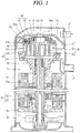
- FIG. 1 is a longitudinal sectional view of a low pressure type scroll compressor according to the related art.
- the low pressure type scroll compressor includes a driving motor 20 disposed in an inner space 11 of a hermetic casing 10 to generate a rotation force, and a main frame 30 disposed at an upper side of the driving motor 20.
- the orbiting wrap 40 is disposed on an upper surface of the main frame 30 to be orbited by an Oldham-ring (not illustrated), and the non-orbiting scroll 50 is provided on an upper side of the orbiting scroll 40 to be engaged with the orbiting scroll 40 and thus form compression chambers P.
- a rotation shaft 25 is coupled to a rotor 22 of the driving motor 20, the orbiting scroll 40 is eccentrically coupled to the rotation shaft 25, and the non-orbiting scroll 50 is coupled to the main frame 30 in a manner of being restricted from being orbited.
- a back pressure chamber assembly 60 for preventing the non-orbiting scroll 50 from being raised up due to pressure of the compression chamber P during an operation is coupled to an upper side of the non-orbiting scroll 50.
- the back pressure chamber assembly 60 is provided with a back pressure chamber 60a in which a refrigerant of intermediate pressure is filled.
- a high/low pressure dividing plate 15 is provided on an upper side of the back pressure chamber assembly 60.
- the high/low pressure dividing plate 15 supports a rear surface of the back pressure chamber assembly 60 and simultaneously divides the inner space 11 of the casing 10 into a low pressure portion 11 as a suction space and a high pressure portion 12 as a discharge space.
- the high/low pressure dividing plate 15 has an outer circumferential surface attached to an inner circumferential surface of the casing 10 in a welding manner, and is provided with a discharge hole 15a formed through a central portion thereof to communicate with a discharge port 54 of the non-orbiting scroll 50.
- a non-explained reference numeral 13 denotes a suction pipe
- 14 denotes a discharge pipe
- 18 denotes a sub frame
- 21 denotes a stator
- 21a denotes a winding coil
- 41 denotes a disk portion of the orbiting scroll
- 42 denotes the orbiting wrap
- 51 denotes a disk portion of the non-orbiting scroll
- 52 denotes the non-orbiting wrap
- 53 denotes a suction port
- 61 denotes a modulation ring for varying a capacity.
- the orbiting scroll 40 then performs an orbiting motion with respect to the non-orbiting scroll 50 by the Oldham-ring. Accordingly, a pair of compression chambers P is formed between the orbiting scroll 40 and the non-orbiting scroll 50 such that a refrigerant can be sucked, compressed and discharged.
- the refrigerant compressed in the compression chambers P is partially introduced from the intermediate pressure chamber into the back pressure chamber 60a through a back pressure hole (not illustrated).
- the refrigerant of intermediate pressure introduced into the back pressure chamber 60a generates back pressure to lift a floating plate 65 constructing the back pressure chamber assembly 60.
- the floating plate 65 is closely adhered on a lower surface of the high/low pressure dividing plate 15 such that the high pressure portion 12 and the low pressure portion 11 are divided from each other.
- pressure of the back pressure chamber pushes the non-orbiting scroll 50 toward the orbiting scroll 40, to maintain the compression chamber P between the non-orbiting scroll 50 and the orbiting scroll 40 in an air-tight state.
- the scroll compressor may vary a compression capacity according to requirement of a refrigerating device with the compressor.
- the modulation ring 61 and a lift ring 62 are additionally provided on the disk portion 51 of the non-orbiting scroll 50, and a control valve 63 which communicates with the back pressure chamber 60a through a first communication passage 61a is provided on one side of the modulation ring 61.
- a second communication passage 61b is formed between the modulation ring 61 and the lift ring 62, and a third communication passage 61c which is open when the modulation ring 61 rises is formed between the modulation ring 61 and the non-orbiting scroll 50.
- One end of the third communication passage 61c communicates with the intermediate compression chamber P and another end thereof communicates with the low pressure portion 11 of the casing 10.
- the control valve 63 closes the first communication passage 61a and opens the second communication passage 61b to communicate with the low pressure portion 11, thereby preventing the modulation ring 61 from being raised up. Accordingly, the third communication passage 61c is maintained in a closed state.
- the control valve 63 communicates the first communication passage 61a with the second communication passage 61b. Accordingly, the modulation ring 61 is raised up to open the third communication passage 61c, such that the refrigerant within the intermediate compression chamber P is partially leaked into the low pressure portion 11. This results in a reduction of a capacity of the compressor.
- the capacity varying apparatus of the related art scroll compressor which includes the modulation ring 61, the lift ring 62 and the control valve 63 requires such a lot of components.
- the first communication passage 61a, the second communication passage 61b and the third communication passage 61c should be formed on the modulation ring 61 to operate the modulation ring 61, which makes the structure of the modulation ring 61 complicated.
- the capacity varying apparatus of the related art scroll compressor should fast lift the modulation ring 61 using the refrigerant of the back pressure chamber 60a.
- the modulation ring 61 is formed in a ring shape and coupled with the control valve 63, a weight of the modulation ring 61 increases which makes it difficult to fast lift the modulation ring 61.
- a passage for lifting the modulation ring 61 is long and even the refrigerant should be introduced into a space between the modulation ring 61 and the lift ring 62 to lift the modulation ring 61, but the pressure of the back pressure chamber 60a still exists on the upper surface of the modulation ring 61. Therefore, the lifting of the modulation ring 61 is not easy and responsiveness of the valve is lowered, which results in interfering with a fast control of the variation of the capacity of the compressor.
- an aspect of the detailed description is to provide a scroll compressor capable of reducing fabricating costs by simplifying a structure of a capacity varying apparatus.
- Another aspect of the detailed description is to provide a scroll compressor capable of relaxing restrictions on components constructing a capacity varying apparatus.
- Another aspect of the detailed description is to provide a scroll compressor capable of easily supplying power for operating a capacity varying apparatus.
- Another aspect of the detailed description is to provide a scroll compressor capable of enhancing responsiveness by simplifying a control of a capacity varying apparatus.
- a scroll compressor having a high/low pressure dividing plate for dividing an inner space of a casing into a high pressure portion and a low pressure portion, the compressor including a passage formed between a non-orbiting scroll and a back pressure chamber assembly to communicate with an intermediate pressure chamber, and a valve provided at the passage to open and close the passage.
- the scroll compressor may further include a check valve disposed at the passage and opened and closed according to a pressure difference of the intermediate pressure chamber.
- a scroll compressor including a casing having a hermetic inner space divided into a low pressure portion and a high pressure portion, an orbiting scroll disposed within the inner space of the casing and performing an orbiting motion, a non-orbiting scroll forming a compression chamber together with the orbiting scroll, the compression chamber having a suction chamber, an intermediate pressure chamber and a discharge chamber, a back pressure chamber assembly coupled to the non-orbiting scroll to form a back pressure chamber, a valve accommodation groove formed on at least one of the non-orbiting scroll or the back pressure chamber assembly, a bypass hole formed from the intermediate pressure chamber into the valve accommodation groove in a penetrating manner, a check valve accommodated in the valve accommodation groove and opening and closing the bypass hole according to pressure of the intermediate pressure chamber, a communication passage communicating the valve accommodation groove and the low pressure portion with each other, and a control valve selectively opening and closing the communication passage.
- bypass hole may be provided in plurality spaced apart from each other by a predetermined crank angle
- the check valve may be provided in plurality to open and close the plurality of bypass holes, respectively.
- the valve accommodation groove may be provided in plurality to accommodate the plurality of check valves, respectively, a communication groove may be provided between the plurality of valve accommodation grooves to communicate the plurality of valve accommodation grooves with each other.
- the control valve may be disposed within the inner space of the casing.
- the control valve may be electrically connected to a terminal mounted to the casing.
- the control valve may be coupled to the non-orbiting scroll or the back pressure chamber assembly at the communication passage.
- the communication passage may be coupled with one end of a communication pipe that extends into the inner space of the casing, and another end of the communication pipe may extend through the non-orbiting scroll.
- the control valve may be disposed on the another end of the communication pipe.
- the non-orbiting scroll may be disposed to be movable up and down with respect to the orbiting scroll.
- the communication pipe may be provided in plurality, and the plurality of communication pipes may be connected by a connection member.
- the connection member may be slidably coupled to at least one communication pipe in a lengthwise direction.
- a sealing member may be provided between an inner circumferential surface of the connection member and an outer circumferential surface of the communication pipe.
- the communication passage may be coupled with one end of a communication pipe that extends to outside of the casing, and another end of the communication pipe may be connected to the low pressure portion of the casing.
- the control valve may be disposed at the communication pipe at the outside of the casing.
- the communication pipe may be provided in plurality, and the plurality of communication pipes may be connected by a connection member.
- the connection member may be slidably coupled to at least one communication pipe in a lengthwise direction.
- a sealing member may be provided between an inner circumferential surface of the connection member and an outer circumferential surface of the communication pipe.
- the control valve may be connected directly to an external power source.
- a scroll compressor including a casing, a high/low pressure dividing plate fixed to an inner space of the casing to divide the inner space of the casing into a low pressure portion and a high pressure portion, a main frame disposed with being spaced apart from the high/low pressure dividing plate, an orbiting scroll performing an orbiting motion while being supported on the main frame, a non-orbiting scroll provided to be movable up and down with respect to the orbiting scroll, and forming a suction chamber, an intermediate pressure chamber and a discharge chamber together with the orbiting scroll, a back pressure plate fixed to the non-orbiting scroll in the low pressure portion, and having a space portion communicating with the intermediate pressure chamber and having an open surface facing the high/low pressure dividing plate, and a floating plate movably coupled to the back pressure plate to hermetically seal the space portion so as to form a back pressure chamber, wherein the non-orbiting scroll comprises a plurality of bypass holes formed from the intermediate pressure chamber to a rear surface of
- control valve may be coupled to a member with the discharge hole of the non-orbiting scroll or the back pressure plate.
- the discharge hole may be coupled with one end of a communication pipe that extends toward the low pressure portion, another end of the communication pipe may extend through the main frame, and the control valve may be disposed at another end of the communication pipe.
- the discharge hole may be coupled with one end of a communication pipe that extends to outside of the casing, and another end of the communication pipe may be connected to the low pressure portion of the casing.
- the control valve may be disposed at the communication pipe at the outside of the casing.
- scroll compressor including a casing having an inner space divided into a low pressure portion and a high pressure portion, a high/low pressure dividing plate dividing the inner space of the casing into the low pressure portion and the high pressure portion, an orbiting member disposed within the casing and performing an orbiting motion, a non-orbiting member forming a compression chamber together with the orbiting member, the compression chamber including a suction chamber, an intermediate pressure chamber and a discharge chamber, a passage disposed on the non-orbiting member to communicate inside and outside of the compression chamber with each other, and an opening/closing valve assembly disposed at outside of the non-orbiting member and opening and closing the passage.
- the opening/closing valve assembly may be disposed within the casing.
- the opening/closing valve assembly may be disposed at outside the casing.
- a scroll compressor according to the present invention may use a less number of components by virtue of installing a check valve in a bypass hole and also simplify a bypass passage for bypassing a refrigerant by virtue of installing a control valve on the bypass hole. This may result in facilitating fabrication of a capacity varying apparatus.
- a refrigerant may be in a state of being already arrived at an outlet of the passage when switching a power operation mode into a saving operation mode, which may allow for fast switching into the saving operation mode.
- a position of a control valve may be changed by using a communication pipe, and thus restriction on a specification of the control valve can be relaxed. This may result in enhancing reliability of a capacity varying apparatus.
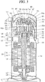
- FIG. 3 is a longitudinal sectional view illustrating a scroll compressor having a capacity varying apparatus in accordance with the present invention
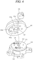
- FIG. 4 is an exploded perspective view of the capacity varying apparatus according to FIG. 3
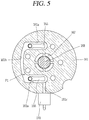
- FIG. 5 is a sectional view taken along the line "VI-VI" of FIG. 3
- FIGS. 6A and 6B are longitudinal sectional views illustrating a power-operation state and a saving-operation state using the capacity varying apparatus in the scroll compressor of FIG. 3 .
- a scroll compressor is configured such that a hermetic inner space of a casing 110 is divided into a low pressure portion 111 as a suction space and a high pressure portion 112 as a discharge space by a high/low pressure dividing plate 115, which is provided on an upper side of a non-orbiting scroll 150 to be explained later.
- the low pressure portion 111 corresponds to a lower space of the high/low pressure dividing plate 115
- the high pressure portion 112 corresponds to an upper space of the high/low pressure dividing plate 115.
- a suction pipe 113 communicating with the low pressure portion 111 and a discharge pipe 114 communicating with the high pressure portion 112 are fixed to the casing 110, respectively, such that a refrigerant can be sucked into the inner space of the casing 110 or discharged out of the casing 110.
- the low pressure portion 111 of the casing 110 is provided with a driving motor 120 having a stator 121 and a rotor 122.
- the stator 121 is fixed to an inner wall surface of the casing 100 in a shrink-fitting manner, and a rotation shaft 125 is inserted into a central portion of the rotor 122.
- a coil 121a is wound on the stator 121.
- a lower side of the rotation shaft 125 is rotatably supported by an auxiliary bearing 117 provided on a lower portion of the casing 110.
- the auxiliary bearing 117 is supported by a lower frame 118 fixed to an inner surface of the casing 110 and thus can stably support the rotation shaft 125.
- the lower frame 118 may be welded on an inner wall surface of the casing 110.
- a bottom surface of the casing 110 is used as an oil storage space. Oil stored in the oil storage space is carried upwardly by the rotation shaft 125 and the like and thus introduced into a driving unit and the compression chamber for facilitating lubrication.
- An upper end portion of the rotation shaft 125 is rotatably supported by a main frame 130.
- the main frame 130 similar to the lower frame 118, is fixed to the inner wall surface of the casing 110.
- a main bearing portion 131 downwardly protrudes from a lower surface of the main frame 130, and the rotation shaft 125 is inserted into the main bearing portion 131.
- An inner wall surface of the main bearing portion 131 serves as a bearing surface, and supports the rotation shaft 125 together with the oil, such that the rotation shaft 125 can smoothly rotate.
- An orbiting scroll 140 is disposed on an upper surface of the main frame 130.
- the orbiting scroll 140 includes a disk portion 141 having a shape similar to a disk, and an orbiting wrap 142 spirally formed on one side surface of the disk portion 141.
- the orbiting wrap 142 forms the compression chambers P together with a non-orbiting wrap 152 of the non-orbiting scroll 150 to be explained later.
- the disk portion 141 of the orbiting scroll 140 orbits in a state of being supported by the upper surface of the main frame 130.
- An Oldham-ring 136 is interposed between the disk portion 141 and the main frame 130 to prevent self-rotation of the orbiting scroll 140.
- a boss 143 in which the rotation shaft 125 is inserted is formed on a lower surface of the disk portion 141 of the orbiting scroll 140, and accordingly the orbiting scroll 140 is orbited by the rotational force of the rotation shaft 125.
- the non-orbiting scroll 150 engaged with the orbiting scroll 140 are disposed on the orbiting scroll 140.
- the non-orbiting scroll 150 is provided to be movable up and down with respect to the orbiting scroll 140.
- the non-orbiting scroll 150 is supported with being laid on an upper surface of the main frame 130 in a manner that a plurality of guide pins (not illustrated) inserted into the main frame 130 are inserted in a plurality of guide holes (not illustrated) formed on an outer circumferential portion of the non-orbiting scroll 150.
- the non-orbiting scroll 150 includes a disk portion 151 formed in a disk shape on an upper surface of a body thereof, and the non-orbiting wrap 152 spirally formed on a lower portion of the disk portion 151 and engaged with the orbiting wrap 142 of the orbiting scroll 140.
- a suction port 153 through which a refrigerant existing in the low pressure portion 111 is sucked is formed through a side surface of the non-orbiting scroll 150, and a discharge port 154 through which a compressed refrigerant is discharged is formed through an approximately central portion of the disk portion 151.
- the orbiting wrap 142 and the non-orbiting wrap 152 form a plurality of compression chambers P.
- the compression chambers are reduced in volume while orbiting toward the discharge port 154, thereby compressing the refrigerant. Therefore, the lowest pressure is existing in a compression chamber adjacent to the suction port 153, the highest pressure is existing in a compression chamber communicating with the discharge port 154, and pressure of a compression chamber present therebetween is intermediate pressure which has a value between suction pressure of the suction port 153 and discharge pressure of the discharge port 154.
- the intermediate pressure is applied to a back pressure chamber 160a to be explained later and serves to press the non-orbiting scroll 150 toward the orbiting scroll 140. Accordingly, a scroll-side back pressure hole, which communicates with one of areas having the intermediate pressure and through which the refrigerant is discharged, is formed on the disk portion 151.
- a back pressure plate 161 which forms a part of the back pressure chamber assembly 160 is fixed to a top of the disk portion 151 of the non-orbiting scroll 150.
- the back pressure plate 161 is formed approximately in an annular shape, and provided with a supporting plate 162 which is brought into contact with the disk portion 151 of the non-orbiting scroll 150.
- the supporting plate 162 has a shape of an annular plate with a hollow center. Also, as illustrated in FIG. 5 , a plate-side back pressure hole (not illustrated) communicating with the scroll-side back pressure hole is formed through the supporting plate 162.
- First and second annular walls 163 and 164 are formed on an upper surface of the supporting plate 162 along an inner circumferential portion and an outer circumferential portion of the supporting plate 162.
- An outer circumferential surface of the first annular wall 163, an inner circumferential surface of the second annular wall 164 and the upper surface of the supporting plate 162 form the back pressure chamber 160a formed in the annular shape.
- a floating plate 165 forming an upper surface of the back pressure chamber 160a is provided on an upper side of the back pressure chamber 160a.
- a sealing end portion 166 is disposed on an upper end portion of an inner space of the floating plate 165.
- the sealing end portion 166 upwardly protrudes from a surface of the floating plate 165, and has an inner diameter which is not so great to obscure an intermediate discharge port 167.
- the sealing end portion 166 comes in contact with a lower surface of the high/low pressure dividing plate 115, such that a discharged refrigerant can be discharged to the high pressure portion 112 without being leaked into the low pressure portion 111.
- a non-explained reference numeral 168 denotes a check valve.
- the rotation shaft 125 rotates.
- the orbiting scroll 140 coupled to an upper end portion of the rotation shaft 125 performs an orbiting motion with respect to the non-orbiting scroll 150, in response to the rotation of the rotation shaft 125.
- a plurality of compression chambers P formed between the non-orbiting wrap 152 and the orbiting wrap 142 move toward the discharge port 154. During the movement, a refrigerant is compressed.
- the compression chamber P communicates with the scroll-side back pressure hole (not illustrated) before arriving at the discharge port 154, the refrigerant is partially introduced into the plate-side back pressure hole (not illustrated) formed through the supporting plate 162, which results in applying intermediate pressure to the back pressure chamber 160a that is formed by the back pressure plate 161 and the floating plate 165. Accordingly, the back pressure plate 161 is affected by pressure applied in a downward direction and the floating plate 165 is affected by pressure applied in an upward direction.
- the intermediate pressure of the back pressure chamber 160a also affects the non-orbiting scroll 150.
- the non-orbiting scroll 150 is unable to be moved downward due to already being brought into contact with the disk portion 141 of the orbiting scroll 140, and thus the floating plate 165 is moved upward.
- the floating plate 165 prevents a leakage of the refrigerant from the discharge space as the high pressure portion 112 into the suction space as the low pressure portion 111, in response to the sealing end portion 166 thereof being brought into contact with a lower end portion of the high/low pressure dividing plate 115.
- the non-orbiting scroll 150 is pushed toward the orbiting scroll 140 by the pressure of the back pressure chamber 160a, thereby blocking the leakage of the refrigerant between the orbiting scroll 140 and the non-orbiting scroll 150.
- bypass holes 151b that communicate with the intermediate pressure chamber are formed through the disk portion 151 of the non-orbiting scroll 150 in a direction from the intermediate pressure chamber toward a rear surface of the disk portion 151.
- the bypass holes 151b are formed with an interval of 180° with facing each other such that refrigerants with the same intermediate pressure in inner and outer pockets can be bypassed.
- the two bypass holes 151b may be formed at the same crank angle or only one bypass hole may be formed such that both of the inner and outer pockets communicate with each other.
- a check valve 155 for opening and closing the bypass hole 151b is provided at each of the bypass holes 151b.
- the check valve 155 may be configured as a reed valve which is opened and closed according to pressure of the intermediate pressure chamber.
- a plurality of valve accommodation grooves 161a in which the check valves 155 are accommodated, respectively, are formed on a lower surface of the back pressure plate 161 corresponding to the rear surface of the disk portion 151 of the non-orbiting scroll 150.
- the plurality of valve accommodation grooves 161a may communicate with each other through a communication groove 161b.
- a discharge hole 161c for guiding a bypassed refrigerant into the suction space as the low pressure portion 111 of the casing 110 is connected to one of the plurality of valve accommodation grooves 161a or the communication groove 161b. Another end of the discharge hole 161c penetrates through an outer circumferential surface of the back pressure plate 161. Accordingly, when the valve accommodation grooves 161a, the communication groove 161b and the discharge hole 161c form the intermediate pressure chamber P1, in which a refrigerant of intermediate pressure is stored, when the check valves 155 are open.
- a control valve 170 is provided on an outer circumferential surface of the back pressure plate 161.
- the control valve 170 communicates with an end portion of the discharge hole 161c and selectively opens and closes the discharge hole 161c according to an operating mode of the compressor.
- the control valve 170 may be configured as a solenoid valve that operates according to supply or non-supply of external power.
- the control valve 170 may be electrically connected to a separate terminal 176 provided in the casing 110.
- the control valve 170 is maintained in a closed state.
- a refrigerant within the intermediate pressure chamber of the compression chamber P is partially discharged into the valve accommodation groove 161a through the bypass hole 151b in a manner of opening the check valve 155.
- This refrigerant remains in a state of being filled in the valve accommodation groove 161a, the communication groove 161b and the discharge hole 161c. Accordingly, the refrigerant does not flow out of the compression chamber P any more, which results in continuing the power operation of the compressor.
- the capacity varying apparatus may include the check valve and the control valve, which may result in reducing a number of components and simplifying a path for bypassing the refrigerant, thereby facilitating fabrication processes.
- control valve can be installed on an end portion of a passage. Accordingly, the refrigerant may already stay near an outlet port of the passage when a power operation is switched into a saving operation, which may thus allow for fast switching into the saving operation that much.
- valve accommodation grooves, the communication groove and the discharge hole may be formed on a rear surface of the disk portion 151 of the non-orbiting scroll 150. That is, as illustrated in FIG. 7 , a plurality of valve accommodation grooves 151c are recessed by predetermined depths into the rear surface of the disk portion 151 of the non-orbiting scroll 150, respectively, and a communication groove 151d is recessed by a predetermined depth between the plurality of valve accommodation grooves 151c. Also, a discharge hole 151e may be formed from the valve accommodation groove 151c or the communication groove 151d to the outer circumferential surface of the non-orbiting scroll 150 in a penetrating manner.
- valve accommodation grooves 151c, the communication groove 151d and the discharge hole 151e are formed on the rear surface of the disk portion 151 of the non-orbiting scroll 150, the basic construction and operation effects are the same as or similar to those of the aforementioned embodiment.
- the valve accommodation grooves 151c, the communication groove 151d and the discharge hole 151e are formed on the rear surface of the disk portion 151 of the non-orbiting scroll 150, lengths of the bypass holes 151b may be reduced, thereby reducing a dead volume.
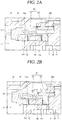
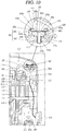
- control valve is coupled directly to the back pressure plate or the non-orbiting scroll, but this embodiment illustrates that the control valve is provided adjacent to the driving motor with a relatively wide extra space.
- one end of a first communication pipe 171 is connected to the discharge hole 161c, and another end of the first communication pipe 171 is connected to one end of a second communication pipe 172, which penetrates through the main frame 130 and extends toward the driving motor 120 based on the main frame 130.
- the control valve 170 is disposed on another end of the second communication pipe 172.
- the control valve 170 may be fixed to a lower surface of the main frame 130 to be electrically connected to the terminal 176 separately provided through the casing 110.
- the control valve 170 cannot be fixed to a fixed member such as the main frame 130. Therefore, the first communication pipe 171 and the second communication pipe 172 may preferably be connected to each other by use of a connection member 175, which is provided between the two communication pipes to be slidable with respect to at least one of the two communication pipes in a lengthwise direction.
- a sealing member 175a is preferably provided between an inner circumferential surface of the connection member 175 and an outer circumferential surface of the communication pipe 171 slidably coupled to the connection member 175.
- the capacity varying apparatus provides the same/like basic configuration and operation effects to the foregoing embodiment, so detailed description will be omitted.
- this embodiment may allow the control valve 170 to be installed in a relatively wide space, compared to the foregoing embodiment, thereby relaxing restriction for the specification of the control valve 170.
- control valve is provided in the inner space of the casing, but this embodiment illustrates that the control valve is provided outside the casing.
- one end of the first communication pipe 171 is connected to the discharge hole 161c, and another end of the first communication pipe 171 is connected to one end of the second communication pipe 172 that externally extends through the casing 110.
- Another end of the second communication pipe 172 is connected to an inlet side of the control valve 170 at the outside of the casing 110, and an outlet side of the control valve 170 is connected one end of a third communication pipe 173.
- An outlet of the third communication pipe 173 is coupled through the casing 110 to communicate with the low pressure portion 111 of the casing 110.
- the first communication pipe 171 and the second communication pipe 172 may preferably be connected to each other by use of the connection member 175, which is provided between the two communication pipes 171 and 172 to be slidable with respect to at least one (the first communication pipe in the drawing) of the two communication pipes 171 and 172 in a lengthwise direction.
- the sealing member 175a is preferably provided between an inner circumferential surface of the connection member 175 and an outer circumferential surface of the communication pipe 171 slidably coupled to the connection member 175.
- the capacity varying apparatus provides the same/like basic configuration and operation effects to the foregoing embodiment, so detailed description will be omitted.
- this embodiment may allow the control valve 170 to be connected directly to an external power source, by virtue of coupling the control valve to the outside of the casing. Accordingly, any separate terminal does not need to be mounted to the casing 110, thereby simplifying a structure for electrically connecting the control valve 170 that much.
- the scroll compressor continuously operates while a gap between the high pressure portion and the low pressure portion is blocked.
- temperature of the discharge space of the high pressure portion may increase up to a preset temperature or more. In this instance, some components of the compressor may be damaged due to such high temperature.
- an overheat preventing unit 180 may be disposed on the high/low pressure dividing plate 115 according to this embodiment.
- the overheat preventing unit 180 may communicate the high pressure portion 112 and the low pressure portion 111 with each other such that a refrigerant of the high pressure portion 112 is leaked into the low pressure portion 111, when temperature of the high pressure portion 112 is raised up to a preset temperature or more.
- the leaked hot refrigerant arouses an operation of an overload breaker 121b provided on an upper end of the winding coil 121a of the stator 121, thereby stopping the operation of the compressor. Therefore, the overheat preventing unit 180 is preferably configured to be sensitive to temperature of the discharge space.
- the overheat preventing unit 180 may be spaced apart from the high/low pressure dividing plate 115 by a predetermined interval, if possible, taking into account the point that the high/low pressure dividing plate 115 is formed of a thin plate material and divides the high pressure portion 112 and the low pressure portion 111. This may allow the overheat preventing unit 180 to be less affected in view of temperature by the low pressure portion 111 with relatively low temperature.
- the overheat preventing unit 180 may be provided with a body 181 which is separately fabricated to accommodate a valve plate 185, and the body 181 may then be coupled to the high/low pressure dividing plate 115. Accordingly, the high/low pressure dividing plate and the valve plate may be spaced apart from each other by a predetermined interval, such that the valve plate can be less affected by the high/low pressure dividing plate.
- the body 181 may be made of the same material as the high/low pressure dividing plate 115. However, the body 181 may preferably be made of a material with a low heat transfer rate, in terms of insulation.
- the body 181 may be provided with a valve accommodating portion 182 having a valve space, and a coupling portion 183 protruding from a center of an outer surface of the valve accommodating portion 182 by a predetermined length and coupling the body 181 to the high/low pressure dividing plate 115.
- the valve accommodating portion 182 includes a mounting portion 182a formed in a disk-like shape and having the valve plate 185 mounted on an upper surface thereof, and a side wall portion 182b extending from an edge of the mounting portion 182a into an annular shape and forming the valve space together with an upper surface of the mounting portion 182a.
- the mounting portion 182a may be thicker than the side wall portion 182b in thickness. However, when the mounting portion is thicker, an effect of holding heat may be generated. Therefore, the thickness of the mounting portion may alternatively be thinner than that of the side wall portion within a range of ensuring reliability.
- a stepped surface 182c supported by the high/low pressure dividing plate 115 is formed on a lower surface of the mounting portion 182a. Accordingly, a lower surface of an outer mounting portion 182d which is located outside the stepped surface 182c of the lower surface of the mounting portion 182a may be spaced apart from an upper surface of the high/low pressure dividing plate 115 by a predetermined height (interval) h. This may result in reducing a contact area between the body and the high/low pressure dividing plate and simultaneously enhancing reliability by allowing a refrigerant of the discharge space to be introduced between the body and the high/low pressure dividing plate.
- an insulating material such as a gasket 194, which serves as a sealing member, may preferably be provided between the stepped surface 182c and the high/low pressure dividing plate 115, in the aspect of preventing heat transfer between the body 181 and the high/low pressure dividing plate 115.
- a communication hole 181a through which the high pressure portion 112 and the low pressure portion 111 communicate with each other is formed from a center of the upper surface of the mounting portion 182a to a lower end of the coupling portion 183.
- a damper (not illustrated) in which a sealing protrusion 185c of the valve plate 185 is inserted may be formed in a tapering manner on an inlet of the communication hole 181a, namely, an end portion of the upper surface of the mounting portion 182a.
- a supporting protrusion 182e is formed on an upper end of the side wall portion 182b.
- the supporting protrusion 182e is bent after inserting a valve stopper 186 therein, so as to support the valve stopper 186.
- the valve stopper 186 may be formed in a ring shape with a first gas hole 186a formed at a center thereof to allow a refrigerant of the high pressure portion 112 to always come in contact with a first contact surface 185a of the valve plate 185.
- the mounting portion 182a may be provided with at least one second gas hole 182f through which the refrigerant of the high pressure portion 112 always comes in contact with a second contact surface 185b of the valve plate 185. Accordingly, the refrigerant of the discharge space may come in contact directly with the first contact surface 185a of the valve plate 185 through the first gas hole 186a and simultaneously come in contact directly with the second contact surface 185b of the valve plate 185 through the second gas hole 182f. This may result in reducing a temperature difference between the first contact surface 185a and the second contact surface 185b of the valve plate 185 and simultaneously increasing a responding speed of the valve plate 185.
- the valve plate 185 may be configured as a bimetal to be thermally transformed according to temperature of the high pressure portion 112 and thereby open and close the communication hole 181a.
- the sealing protrusion 185c protrudes from a central portion of the valve plate 185 toward the communication hole 181a, and a plurality of refrigerant holes 185d through which the refrigerant flows during an opening operation are formed around the sealing protrusion 185c.
- a thread is formed on an outer circumferential surface of the coupling portion 183 such that the coupling portion 183 can be screw-coupled to a coupling hole 115b provided on the high/low pressure dividing plate 115.
- the coupling portion 183 may be press-fitted into the coupling hole 115b or coupled to the coupling hole 115b in a welding manner or by using an adhesive.
- the overheat preventing unit 180 of the scroll compressor may extend a path along which low refrigerant temperature of the low pressure portion 111 is transferred to the valve plate 185 by a heat transfer through the high/low pressure dividing plate 115, which may increase an insulating effect and accordingly allow the valve plate 185 to be much less affected by the temperature of the low pressure portion 111.
- valve plate 185 may be located in the discharge space of the high pressure portion 122 by being spaced apart from the upper surface 115c of the high/low pressure dividing plate 115, adjacent to the high pressure portion 112, by the predetermined height h. Accordingly, the valve plate 185 may be mostly affected by the temperature of the high pressure portion 112, and thus sensitively react with respect to the increase in the temperature of the high pressure portion 112.
- the valve plate may fast be open and the refrigerant of the high pressure portion may fast flow toward the low pressure portion through the bypass holes.
- the refrigerant arouses the operation of the overload breaker provided in the driving motor and thereby the compressor is stopped.
Landscapes
- Engineering & Computer Science (AREA)
- Mechanical Engineering (AREA)
- General Engineering & Computer Science (AREA)
- Physics & Mathematics (AREA)
- Fluid Mechanics (AREA)
- Rotary Pumps (AREA)
- Applications Or Details Of Rotary Compressors (AREA)
Applications Claiming Priority (1)
| Application Number | Priority Date | Filing Date | Title |
|---|---|---|---|
| KR1020160022081A KR101747175B1 (ko) | 2016-02-24 | 2016-02-24 | 스크롤 압축기 |
Publications (2)
| Publication Number | Publication Date |
|---|---|
| EP3211237A1 EP3211237A1 (en) | 2017-08-30 |
| EP3211237B1 true EP3211237B1 (en) | 2019-06-05 |
Family
ID=57956178
Family Applications (1)
| Application Number | Title | Priority Date | Filing Date |
|---|---|---|---|
| EP17154150.1A Active EP3211237B1 (en) | 2016-02-24 | 2017-02-01 | Scroll compressor |
Country Status (6)
| Country | Link |
|---|---|
| US (1) | US10428818B2 (he) |
| EP (1) | EP3211237B1 (he) |
| KR (1) | KR101747175B1 (he) |
| CN (1) | CN107120271B (he) |
| IL (1) | IL250226B (he) |
| MX (1) | MX377102B (he) |
Families Citing this family (30)
| Publication number | Priority date | Publication date | Assignee | Title |
|---|---|---|---|---|
| US7988433B2 (en) | 2009-04-07 | 2011-08-02 | Emerson Climate Technologies, Inc. | Compressor having capacity modulation assembly |
| US9651043B2 (en) | 2012-11-15 | 2017-05-16 | Emerson Climate Technologies, Inc. | Compressor valve system and assembly |
| US9249802B2 (en) | 2012-11-15 | 2016-02-02 | Emerson Climate Technologies, Inc. | Compressor |
| US9790940B2 (en) | 2015-03-19 | 2017-10-17 | Emerson Climate Technologies, Inc. | Variable volume ratio compressor |
| US10598180B2 (en) | 2015-07-01 | 2020-03-24 | Emerson Climate Technologies, Inc. | Compressor with thermally-responsive injector |
| KR101800261B1 (ko) | 2016-05-25 | 2017-11-22 | 엘지전자 주식회사 | 스크롤 압축기 |
| KR101839886B1 (ko) * | 2016-05-30 | 2018-03-19 | 엘지전자 주식회사 | 스크롤 압축기 |
| US10801495B2 (en) | 2016-09-08 | 2020-10-13 | Emerson Climate Technologies, Inc. | Oil flow through the bearings of a scroll compressor |
| US10890186B2 (en) | 2016-09-08 | 2021-01-12 | Emerson Climate Technologies, Inc. | Compressor |
| JP6948531B2 (ja) * | 2016-11-24 | 2021-10-13 | パナソニックIpマネジメント株式会社 | インジェクション機能を備えた圧縮機 |
| US10753352B2 (en) | 2017-02-07 | 2020-08-25 | Emerson Climate Technologies, Inc. | Compressor discharge valve assembly |
| US11022119B2 (en) | 2017-10-03 | 2021-06-01 | Emerson Climate Technologies, Inc. | Variable volume ratio compressor |
| US10962008B2 (en) | 2017-12-15 | 2021-03-30 | Emerson Climate Technologies, Inc. | Variable volume ratio compressor |
| KR101934295B1 (ko) * | 2018-01-16 | 2019-01-02 | 엘지전자 주식회사 | 스크롤 압축기 |
| US10995753B2 (en) | 2018-05-17 | 2021-05-04 | Emerson Climate Technologies, Inc. | Compressor having capacity modulation assembly |
| KR20200009915A (ko) | 2018-07-20 | 2020-01-30 | 엘지전자 주식회사 | 스크롤 압축기 |
| WO2020151364A1 (zh) * | 2019-01-24 | 2020-07-30 | 艾默生环境优化技术(苏州)有限公司 | 阀组件及压缩机 |
| US11656003B2 (en) | 2019-03-11 | 2023-05-23 | Emerson Climate Technologies, Inc. | Climate-control system having valve assembly |
| KR102752768B1 (ko) * | 2019-07-24 | 2025-01-14 | 한온시스템 주식회사 | 스크롤 압축기 |
| DE112021001789T5 (de) * | 2020-03-23 | 2023-01-26 | Hanon Systems | Spiralverdichter |
| CN111878394A (zh) * | 2020-08-31 | 2020-11-03 | 广东美的环境科技有限公司 | 压缩机和制冷设备 |
| JP7483638B2 (ja) * | 2021-01-05 | 2024-05-15 | 三菱重工サーマルシステムズ株式会社 | スクロール圧縮機 |
| US11655813B2 (en) | 2021-07-29 | 2023-05-23 | Emerson Climate Technologies, Inc. | Compressor modulation system with multi-way valve |
| US12259163B2 (en) | 2022-06-01 | 2025-03-25 | Copeland Lp | Climate-control system with thermal storage |
| US11846287B1 (en) | 2022-08-11 | 2023-12-19 | Copeland Lp | Scroll compressor with center hub |
| CN115596666A (zh) * | 2022-10-18 | 2023-01-13 | 旭星新能源科技(苏州)有限公司(Cn) | 一种涡旋压缩机的分体密封结构 |
| US11965507B1 (en) | 2022-12-15 | 2024-04-23 | Copeland Lp | Compressor and valve assembly |
| US12416308B2 (en) | 2022-12-28 | 2025-09-16 | Copeland Lp | Compressor with shutdown assembly |
| US12173708B1 (en) | 2023-12-07 | 2024-12-24 | Copeland Lp | Heat pump systems with capacity modulation |
| US12163523B1 (en) | 2023-12-15 | 2024-12-10 | Copeland Lp | Compressor and valve assembly |
Citations (1)
| Publication number | Priority date | Publication date | Assignee | Title |
|---|---|---|---|---|
| CN202707487U (zh) * | 2012-07-23 | 2013-01-30 | 艾默生环境优化技术(苏州)有限公司 | 压缩机 |
Family Cites Families (29)
| Publication number | Priority date | Publication date | Assignee | Title |
|---|---|---|---|---|
| JPS59203893A (ja) | 1983-05-04 | 1984-11-19 | Hitachi Ltd | スクロ−ル流体機械 |
| JPS60101295A (ja) | 1983-11-08 | 1985-06-05 | Sanden Corp | 圧縮容量可変型のスクロ−ル型圧縮機 |
| JP2550612B2 (ja) | 1987-10-19 | 1996-11-06 | ダイキン工業株式会社 | スクロール形圧縮機の容量制御機構 |
| JPH05340363A (ja) | 1992-06-09 | 1993-12-21 | Hitachi Ltd | スクロール圧縮機 |
| JPH08303361A (ja) | 1995-05-10 | 1996-11-19 | Sanyo Electric Co Ltd | スクロール圧縮機 |
| US5613841A (en) * | 1995-06-07 | 1997-03-25 | Copeland Corporation | Capacity modulated scroll machine |
| JP2974009B1 (ja) | 1998-06-12 | 1999-11-08 | ダイキン工業株式会社 | 多段階容量制御スクロール圧縮機 |
| KR100308289B1 (ko) * | 1998-12-29 | 2002-01-15 | 구자홍 | 스크롤압축기의보호장치 |
| KR100360861B1 (ko) | 1999-12-10 | 2002-11-13 | 주식회사 엘지이아이 | 스크롤 압축기의 진공압축 방지장치 |
| US6412293B1 (en) | 2000-10-11 | 2002-07-02 | Copeland Corporation | Scroll machine with continuous capacity modulation |
| JP2003083269A (ja) | 2001-09-05 | 2003-03-19 | Matsushita Electric Ind Co Ltd | スクロール圧縮機 |
| KR100469461B1 (ko) | 2002-08-28 | 2005-02-02 | 엘지전자 주식회사 | 스크롤 압축기의 용량 가변 장치 |
| KR100486603B1 (ko) | 2003-04-21 | 2005-05-03 | 엘지전자 주식회사 | 스크롤 압축기의 용량 가변 장치 |
| US8156751B2 (en) | 2005-05-24 | 2012-04-17 | Emerson Climate Technologies, Inc. | Control and protection system for a variable capacity compressor |
| US7815423B2 (en) * | 2005-07-29 | 2010-10-19 | Emerson Climate Technologies, Inc. | Compressor with fluid injection system |
| US7674098B2 (en) * | 2006-11-07 | 2010-03-09 | Scroll Technologies | Scroll compressor with vapor injection and unloader port |
| KR101368394B1 (ko) | 2007-10-30 | 2014-03-03 | 엘지전자 주식회사 | 스크롤 압축기 |
| KR100920980B1 (ko) | 2008-02-19 | 2009-10-09 | 엘지전자 주식회사 | 스크롤 압축기의 용량 가변장치 |
| WO2009155109A2 (en) | 2008-05-30 | 2009-12-23 | Emerson Climate Technologies, Inc. | Compressor having capacity modulation system |
| US20100028182A1 (en) * | 2008-07-31 | 2010-02-04 | Hahn Gregory W | Line fed permanent magnet synchronous type motor for scroll compressor with bypass ports |
| KR101056882B1 (ko) | 2009-01-07 | 2011-08-12 | 엘지전자 주식회사 | 스크롤 압축기 |
| US7988433B2 (en) | 2009-04-07 | 2011-08-02 | Emerson Climate Technologies, Inc. | Compressor having capacity modulation assembly |
| US8568118B2 (en) | 2009-05-29 | 2013-10-29 | Emerson Climate Technologies, Inc. | Compressor having piston assembly |
| US8616014B2 (en) | 2009-05-29 | 2013-12-31 | Emerson Climate Technologies, Inc. | Compressor having capacity modulation or fluid injection systems |
| US8840384B2 (en) * | 2009-09-08 | 2014-09-23 | Danfoss Scroll Technologies, Llc | Scroll compressor capacity modulation with solenoid mounted outside a compressor shell |
| US9127677B2 (en) | 2012-11-30 | 2015-09-08 | Emerson Climate Technologies, Inc. | Compressor with capacity modulation and variable volume ratio |
| JP5870056B2 (ja) | 2013-03-19 | 2016-02-24 | 日立アプライアンス株式会社 | スクロール圧縮機 |
| KR102162738B1 (ko) | 2014-01-06 | 2020-10-07 | 엘지전자 주식회사 | 스크롤 압축기 |
| KR102177990B1 (ko) | 2014-05-02 | 2020-11-12 | 엘지전자 주식회사 | 압축기 및 스크롤 압축기 |
-
2016
- 2016-02-24 KR KR1020160022081A patent/KR101747175B1/ko active Active
- 2016-12-22 US US15/388,584 patent/US10428818B2/en active Active
-
2017
- 2017-01-22 IL IL250226A patent/IL250226B/he active IP Right Grant
- 2017-02-01 EP EP17154150.1A patent/EP3211237B1/en active Active
- 2017-02-22 MX MX2017002343A patent/MX377102B/es active IP Right Grant
- 2017-02-24 CN CN201710104227.4A patent/CN107120271B/zh active Active
Patent Citations (1)
| Publication number | Priority date | Publication date | Assignee | Title |
|---|---|---|---|---|
| CN202707487U (zh) * | 2012-07-23 | 2013-01-30 | 艾默生环境优化技术(苏州)有限公司 | 压缩机 |
Also Published As
| Publication number | Publication date |
|---|---|
| IL250226B (he) | 2021-03-25 |
| EP3211237A1 (en) | 2017-08-30 |
| MX2017002343A (es) | 2018-08-16 |
| IL250226A0 (he) | 2017-03-30 |
| US20170241417A1 (en) | 2017-08-24 |
| CN107120271A (zh) | 2017-09-01 |
| KR101747175B1 (ko) | 2017-06-14 |
| MX377102B (es) | 2025-03-07 |
| CN107120271B (zh) | 2020-02-18 |
| US10428818B2 (en) | 2019-10-01 |
Similar Documents
| Publication | Publication Date | Title |
|---|---|---|
| EP3211237B1 (en) | Scroll compressor | |
| US11204035B2 (en) | Scroll compressor having a valve assembly controlling the opening/closing valve to open and close communication passage and bypass holes on fixed scroll | |
| EP3252311B1 (en) | Scroll compressor | |
| US10815999B2 (en) | Scroll compressor having a capacity variable device | |
| US10982674B2 (en) | Scroll compressor with back pressure chamber and back pressure passages | |
| KR20100025539A (ko) | 용량 변조 압축기 | |
| US20230090621A1 (en) | Scroll compressor | |
| EP3211238B1 (en) | Hermetic compressor | |
| JP6605140B2 (ja) | ロータリ圧縮機および冷凍サイクル装置 | |
| EP3415764B1 (en) | Scroll compressor | |
| JP6555543B2 (ja) | スクロール圧縮機 | |
| US10815998B2 (en) | Scroll compressor having a capacity variable device | |
| US10865790B2 (en) | Scroll compressor having a capacity variable device | |
| EP1681468A2 (en) | Rotary compressor | |
| JP2006161701A (ja) | 圧縮機 | |
| JP2006105040A (ja) | 圧縮機 | |
| JP2006022761A (ja) | 圧縮機 |
Legal Events
| Date | Code | Title | Description |
|---|---|---|---|
| PUAI | Public reference made under article 153(3) epc to a published international application that has entered the european phase |
Free format text: ORIGINAL CODE: 0009012 |
|
| STAA | Information on the status of an ep patent application or granted ep patent |
Free format text: STATUS: REQUEST FOR EXAMINATION WAS MADE |
|
| 17P | Request for examination filed |
Effective date: 20170228 |
|
| AK | Designated contracting states |
Kind code of ref document: A1 Designated state(s): AL AT BE BG CH CY CZ DE DK EE ES FI FR GB GR HR HU IE IS IT LI LT LU LV MC MK MT NL NO PL PT RO RS SE SI SK SM TR |
|
| AX | Request for extension of the european patent |
Extension state: BA ME |
|
| RBV | Designated contracting states (corrected) |
Designated state(s): AL AT BE BG CH CY CZ DE DK EE ES FI FR GB GR HR HU IE IS IT LI LT LU LV MC MK MT NL NO PL PT RO RS SE SI SK SM TR |
|
| STAA | Information on the status of an ep patent application or granted ep patent |
Free format text: STATUS: EXAMINATION IS IN PROGRESS |
|
| 17Q | First examination report despatched |
Effective date: 20180709 |
|
| REG | Reference to a national code |
Ref country code: DE Ref legal event code: R079 Ref document number: 602017004242 Country of ref document: DE Free format text: PREVIOUS MAIN CLASS: F04C0023000000 Ipc: F04C0028260000 |
|
| RIC1 | Information provided on ipc code assigned before grant |
Ipc: F04C 29/12 20060101ALI20181105BHEP Ipc: F04C 18/02 20060101ALI20181105BHEP Ipc: F04C 28/10 20060101ALI20181105BHEP Ipc: F04C 23/00 20060101ALI20181105BHEP Ipc: F04C 28/26 20060101AFI20181105BHEP |
|
| GRAP | Despatch of communication of intention to grant a patent |
Free format text: ORIGINAL CODE: EPIDOSNIGR1 |
|
| STAA | Information on the status of an ep patent application or granted ep patent |
Free format text: STATUS: GRANT OF PATENT IS INTENDED |
|
| INTG | Intention to grant announced |
Effective date: 20181219 |
|
| GRAS | Grant fee paid |
Free format text: ORIGINAL CODE: EPIDOSNIGR3 |
|
| GRAA | (expected) grant |
Free format text: ORIGINAL CODE: 0009210 |
|
| STAA | Information on the status of an ep patent application or granted ep patent |
Free format text: STATUS: THE PATENT HAS BEEN GRANTED |
|
| AK | Designated contracting states |
Kind code of ref document: B1 Designated state(s): AL AT BE BG CH CY CZ DE DK EE ES FI FR GB GR HR HU IE IS IT LI LT LU LV MC MK MT NL NO PL PT RO RS SE SI SK SM TR |
|
| REG | Reference to a national code |
Ref country code: GB Ref legal event code: FG4D |
|
| REG | Reference to a national code |
Ref country code: CH Ref legal event code: EP |
|
| REG | Reference to a national code |
Ref country code: AT Ref legal event code: REF Ref document number: 1140263 Country of ref document: AT Kind code of ref document: T Effective date: 20190615 |
|
| REG | Reference to a national code |
Ref country code: IE Ref legal event code: FG4D |
|
| REG | Reference to a national code |
Ref country code: DE Ref legal event code: R096 Ref document number: 602017004242 Country of ref document: DE |
|
| REG | Reference to a national code |
Ref country code: NL Ref legal event code: MP Effective date: 20190605 |
|
| REG | Reference to a national code |
Ref country code: LT Ref legal event code: MG4D |
|
| PG25 | Lapsed in a contracting state [announced via postgrant information from national office to epo] |
Ref country code: SE Free format text: LAPSE BECAUSE OF FAILURE TO SUBMIT A TRANSLATION OF THE DESCRIPTION OR TO PAY THE FEE WITHIN THE PRESCRIBED TIME-LIMIT Effective date: 20190605 Ref country code: AL Free format text: LAPSE BECAUSE OF FAILURE TO SUBMIT A TRANSLATION OF THE DESCRIPTION OR TO PAY THE FEE WITHIN THE PRESCRIBED TIME-LIMIT Effective date: 20190605 Ref country code: FI Free format text: LAPSE BECAUSE OF FAILURE TO SUBMIT A TRANSLATION OF THE DESCRIPTION OR TO PAY THE FEE WITHIN THE PRESCRIBED TIME-LIMIT Effective date: 20190605 Ref country code: NO Free format text: LAPSE BECAUSE OF FAILURE TO SUBMIT A TRANSLATION OF THE DESCRIPTION OR TO PAY THE FEE WITHIN THE PRESCRIBED TIME-LIMIT Effective date: 20190905 Ref country code: HR Free format text: LAPSE BECAUSE OF FAILURE TO SUBMIT A TRANSLATION OF THE DESCRIPTION OR TO PAY THE FEE WITHIN THE PRESCRIBED TIME-LIMIT Effective date: 20190605 Ref country code: LT Free format text: LAPSE BECAUSE OF FAILURE TO SUBMIT A TRANSLATION OF THE DESCRIPTION OR TO PAY THE FEE WITHIN THE PRESCRIBED TIME-LIMIT Effective date: 20190605 Ref country code: ES Free format text: LAPSE BECAUSE OF FAILURE TO SUBMIT A TRANSLATION OF THE DESCRIPTION OR TO PAY THE FEE WITHIN THE PRESCRIBED TIME-LIMIT Effective date: 20190605 |
|
| PG25 | Lapsed in a contracting state [announced via postgrant information from national office to epo] |
Ref country code: RS Free format text: LAPSE BECAUSE OF FAILURE TO SUBMIT A TRANSLATION OF THE DESCRIPTION OR TO PAY THE FEE WITHIN THE PRESCRIBED TIME-LIMIT Effective date: 20190605 Ref country code: BG Free format text: LAPSE BECAUSE OF FAILURE TO SUBMIT A TRANSLATION OF THE DESCRIPTION OR TO PAY THE FEE WITHIN THE PRESCRIBED TIME-LIMIT Effective date: 20190905 Ref country code: LV Free format text: LAPSE BECAUSE OF FAILURE TO SUBMIT A TRANSLATION OF THE DESCRIPTION OR TO PAY THE FEE WITHIN THE PRESCRIBED TIME-LIMIT Effective date: 20190605 Ref country code: GR Free format text: LAPSE BECAUSE OF FAILURE TO SUBMIT A TRANSLATION OF THE DESCRIPTION OR TO PAY THE FEE WITHIN THE PRESCRIBED TIME-LIMIT Effective date: 20190906 |
|
| REG | Reference to a national code |
Ref country code: AT Ref legal event code: MK05 Ref document number: 1140263 Country of ref document: AT Kind code of ref document: T Effective date: 20190605 |
|
| PG25 | Lapsed in a contracting state [announced via postgrant information from national office to epo] |
Ref country code: NL Free format text: LAPSE BECAUSE OF FAILURE TO SUBMIT A TRANSLATION OF THE DESCRIPTION OR TO PAY THE FEE WITHIN THE PRESCRIBED TIME-LIMIT Effective date: 20190605 Ref country code: AT Free format text: LAPSE BECAUSE OF FAILURE TO SUBMIT A TRANSLATION OF THE DESCRIPTION OR TO PAY THE FEE WITHIN THE PRESCRIBED TIME-LIMIT Effective date: 20190605 Ref country code: EE Free format text: LAPSE BECAUSE OF FAILURE TO SUBMIT A TRANSLATION OF THE DESCRIPTION OR TO PAY THE FEE WITHIN THE PRESCRIBED TIME-LIMIT Effective date: 20190605 Ref country code: RO Free format text: LAPSE BECAUSE OF FAILURE TO SUBMIT A TRANSLATION OF THE DESCRIPTION OR TO PAY THE FEE WITHIN THE PRESCRIBED TIME-LIMIT Effective date: 20190605 Ref country code: SK Free format text: LAPSE BECAUSE OF FAILURE TO SUBMIT A TRANSLATION OF THE DESCRIPTION OR TO PAY THE FEE WITHIN THE PRESCRIBED TIME-LIMIT Effective date: 20190605 Ref country code: CZ Free format text: LAPSE BECAUSE OF FAILURE TO SUBMIT A TRANSLATION OF THE DESCRIPTION OR TO PAY THE FEE WITHIN THE PRESCRIBED TIME-LIMIT Effective date: 20190605 Ref country code: PT Free format text: LAPSE BECAUSE OF FAILURE TO SUBMIT A TRANSLATION OF THE DESCRIPTION OR TO PAY THE FEE WITHIN THE PRESCRIBED TIME-LIMIT Effective date: 20191007 |
|
| PG25 | Lapsed in a contracting state [announced via postgrant information from national office to epo] |
Ref country code: IS Free format text: LAPSE BECAUSE OF FAILURE TO SUBMIT A TRANSLATION OF THE DESCRIPTION OR TO PAY THE FEE WITHIN THE PRESCRIBED TIME-LIMIT Effective date: 20191005 Ref country code: SM Free format text: LAPSE BECAUSE OF FAILURE TO SUBMIT A TRANSLATION OF THE DESCRIPTION OR TO PAY THE FEE WITHIN THE PRESCRIBED TIME-LIMIT Effective date: 20190605 Ref country code: IT Free format text: LAPSE BECAUSE OF FAILURE TO SUBMIT A TRANSLATION OF THE DESCRIPTION OR TO PAY THE FEE WITHIN THE PRESCRIBED TIME-LIMIT Effective date: 20190605 |
|
| REG | Reference to a national code |
Ref country code: DE Ref legal event code: R097 Ref document number: 602017004242 Country of ref document: DE |
|
| PG25 | Lapsed in a contracting state [announced via postgrant information from national office to epo] |
Ref country code: TR Free format text: LAPSE BECAUSE OF FAILURE TO SUBMIT A TRANSLATION OF THE DESCRIPTION OR TO PAY THE FEE WITHIN THE PRESCRIBED TIME-LIMIT Effective date: 20190605 |
|
| PLBE | No opposition filed within time limit |
Free format text: ORIGINAL CODE: 0009261 |
|
| STAA | Information on the status of an ep patent application or granted ep patent |
Free format text: STATUS: NO OPPOSITION FILED WITHIN TIME LIMIT |
|
| PG25 | Lapsed in a contracting state [announced via postgrant information from national office to epo] |
Ref country code: DK Free format text: LAPSE BECAUSE OF FAILURE TO SUBMIT A TRANSLATION OF THE DESCRIPTION OR TO PAY THE FEE WITHIN THE PRESCRIBED TIME-LIMIT Effective date: 20190605 Ref country code: PL Free format text: LAPSE BECAUSE OF FAILURE TO SUBMIT A TRANSLATION OF THE DESCRIPTION OR TO PAY THE FEE WITHIN THE PRESCRIBED TIME-LIMIT Effective date: 20190605 |
|
| 26N | No opposition filed |
Effective date: 20200306 |
|
| PG25 | Lapsed in a contracting state [announced via postgrant information from national office to epo] |
Ref country code: SI Free format text: LAPSE BECAUSE OF FAILURE TO SUBMIT A TRANSLATION OF THE DESCRIPTION OR TO PAY THE FEE WITHIN THE PRESCRIBED TIME-LIMIT Effective date: 20190605 |
|
| REG | Reference to a national code |
Ref country code: CH Ref legal event code: PL |
|
| REG | Reference to a national code |
Ref country code: BE Ref legal event code: MM Effective date: 20200229 |
|
| PG25 | Lapsed in a contracting state [announced via postgrant information from national office to epo] |
Ref country code: MC Free format text: LAPSE BECAUSE OF FAILURE TO SUBMIT A TRANSLATION OF THE DESCRIPTION OR TO PAY THE FEE WITHIN THE PRESCRIBED TIME-LIMIT Effective date: 20190605 Ref country code: LU Free format text: LAPSE BECAUSE OF NON-PAYMENT OF DUE FEES Effective date: 20200201 |
|
| PG25 | Lapsed in a contracting state [announced via postgrant information from national office to epo] |
Ref country code: LI Free format text: LAPSE BECAUSE OF NON-PAYMENT OF DUE FEES Effective date: 20200229 Ref country code: CH Free format text: LAPSE BECAUSE OF NON-PAYMENT OF DUE FEES Effective date: 20200229 |
|
| PG25 | Lapsed in a contracting state [announced via postgrant information from national office to epo] |
Ref country code: IE Free format text: LAPSE BECAUSE OF NON-PAYMENT OF DUE FEES Effective date: 20200201 Ref country code: FR Free format text: LAPSE BECAUSE OF NON-PAYMENT OF DUE FEES Effective date: 20200229 |
|
| PG25 | Lapsed in a contracting state [announced via postgrant information from national office to epo] |
Ref country code: BE Free format text: LAPSE BECAUSE OF NON-PAYMENT OF DUE FEES Effective date: 20200229 |
|
| GBPC | Gb: european patent ceased through non-payment of renewal fee |
Effective date: 20210201 |
|
| PG25 | Lapsed in a contracting state [announced via postgrant information from national office to epo] |
Ref country code: GB Free format text: LAPSE BECAUSE OF NON-PAYMENT OF DUE FEES Effective date: 20210201 |
|
| PG25 | Lapsed in a contracting state [announced via postgrant information from national office to epo] |
Ref country code: MT Free format text: LAPSE BECAUSE OF FAILURE TO SUBMIT A TRANSLATION OF THE DESCRIPTION OR TO PAY THE FEE WITHIN THE PRESCRIBED TIME-LIMIT Effective date: 20190605 Ref country code: CY Free format text: LAPSE BECAUSE OF FAILURE TO SUBMIT A TRANSLATION OF THE DESCRIPTION OR TO PAY THE FEE WITHIN THE PRESCRIBED TIME-LIMIT Effective date: 20190605 |
|
| PG25 | Lapsed in a contracting state [announced via postgrant information from national office to epo] |
Ref country code: MK Free format text: LAPSE BECAUSE OF FAILURE TO SUBMIT A TRANSLATION OF THE DESCRIPTION OR TO PAY THE FEE WITHIN THE PRESCRIBED TIME-LIMIT Effective date: 20190605 |
|
| PGFP | Annual fee paid to national office [announced via postgrant information from national office to epo] |
Ref country code: DE Payment date: 20250106 Year of fee payment: 9 |