EP3211210A1 - Kraftstoffinjektor - Google Patents
Kraftstoffinjektor Download PDFInfo
- Publication number
- EP3211210A1 EP3211210A1 EP17155942.0A EP17155942A EP3211210A1 EP 3211210 A1 EP3211210 A1 EP 3211210A1 EP 17155942 A EP17155942 A EP 17155942A EP 3211210 A1 EP3211210 A1 EP 3211210A1
- Authority
- EP
- European Patent Office
- Prior art keywords
- fuel
- valve element
- injector
- cylinder
- injection
- Prior art date
- Legal status (The legal status is an assumption and is not a legal conclusion. Google has not performed a legal analysis and makes no representation as to the accuracy of the status listed.)
- Granted
Links
Images

Classifications
-
- F—MECHANICAL ENGINEERING; LIGHTING; HEATING; WEAPONS; BLASTING
- F02—COMBUSTION ENGINES; HOT-GAS OR COMBUSTION-PRODUCT ENGINE PLANTS
- F02M—SUPPLYING COMBUSTION ENGINES IN GENERAL WITH COMBUSTIBLE MIXTURES OR CONSTITUENTS THEREOF
- F02M61/00—Fuel-injectors not provided for in groups F02M39/00 - F02M57/00 or F02M67/00
- F02M61/16—Details not provided for in, or of interest apart from, the apparatus of groups F02M61/02 - F02M61/14
- F02M61/18—Injection nozzles, e.g. having valve seats; Details of valve member seated ends, not otherwise provided for
- F02M61/1873—Valve seats or member ends having circumferential grooves or ridges, e.g. toroidal
-
- F—MECHANICAL ENGINEERING; LIGHTING; HEATING; WEAPONS; BLASTING
- F02—COMBUSTION ENGINES; HOT-GAS OR COMBUSTION-PRODUCT ENGINE PLANTS
- F02M—SUPPLYING COMBUSTION ENGINES IN GENERAL WITH COMBUSTIBLE MIXTURES OR CONSTITUENTS THEREOF
- F02M2200/00—Details of fuel-injection apparatus, not otherwise provided for
- F02M2200/06—Fuel-injection apparatus having means for preventing coking, e.g. of fuel injector discharge orifices or valve needles
Definitions
- the invention relates to a fuel injector having the features of the preamble of patent claim 1.
- the fuel flow is interrupted by the fact that in the broadest sense pointed, conical needle presses with a sealing area in the vicinity of the base circle of the cone against another sealing area on the inside of a cone largely formed at the tip nozzle. Between the sealing area and the spray hole (the spray holes in multi-hole nozzles) there is a small dead volume.
- the needle is raised, so that the flow from the fuel is released in the direction of the injection hole.
- the needle is lowered again and the flow of fuel is stopped.
- German patent specification deals with this problem DE 10 2009 009 796 B3
- a method for diagnosis and / or control of internal combustion engines is known.
- cross-sectional changes in particular by coking of the injection holes are determined and it will be introduced at occurring cross-sectional changes corrective measures, in particular measures for cleaning the spray holes.
- a fuel injection device comprising a housing with a valve seat, with at least one fuel outlet device, which is arranged downstream of the valve seat, with at least one valve element, which cooperates with the housing-side valve seat and has a wall portion which is opposite to the fuel outlet opening.
- the object is achieved in that the wall of the valve element opposite the fuel outlet opening is at least approximately parallel to the wall of the housing in the region of the fuel outlet opening.
- the present invention has the object to show a fuel injector, in which a coking of the injection holes and the injector tip (nozzle) is avoided.
- the fuel is sucked back into the cylinder of the internal combustion engine due to the rebounding elasticity of the invention in the spray holes after fuel injection, whereby at least one negative meniscus is formed on the fuel surface in the spray hole. It can also go so far that the injection hole, or the injection holes are partially emptied of fuel by sucking back. As a result, no fuel from the spray hole can reach the surface of the nozzle and coke or burn there. Another advantage is the reduced coking tendency of the spray hole itself. With the measure according to the invention, the future emission laws can be more easily met without possibly further expensive additional measures.
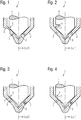
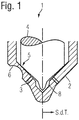
- FIGS. 1 to 4 an embodiment of the invention is shown in each case on a left side of an unnumbered, dot-dashed central axis and right of the central axis of an injector tip according to the prior art (S. d.
- FIG. 1 shows a section through a tip of a fuel injector 1 according to the invention for a first embodiment according to the invention.
- the fuel injector 1 is provided for an injection of fuel, preferably gasoline, directly into a cylinder, not shown, of an internal combustion engine, with an injector 2 at which, in an installed state facing the cylinder end, a spray hole 3 is arranged for introducing the fuel into the Cylinder, wherein the injection hole 3 of a arranged in the injector 2, by an actuating element, not shown, (eg piezo or magnetic actuator), variable position valve element 4 via a sealing seat 5 can be closed, wherein the injection hole 3 is traversed by fuel when the valve element 4 is in a position remote from the cylinder.
- an elasticity is introduced in a region of the sealing seat 5 in the valve element 4 and / or in the injector housing 2.
- the elasticity is generated by a material weakening.
- the material weakening is generated by an outer, radially circumferential annular groove 6 in the injector housing 2.
- FIG. 2 shows a section through a tip of a fuel injector 1 according to the invention for a second embodiment.
- the object in FIG. 2 is different from the object in FIG. 1 in that the elasticity is generated by a material weakening by a radially outer circumferential annular groove 6 in the valve element 4.
- FIG. 3 shows a section through a tip of a fuel injector 1 according to the invention for a third embodiment.
- the object in FIG. 3 is different from the objects in FIGS. 1 and 2 in that the elasticity is generated by a radially outwardly encircling, elastic raised region 7 at the tip of the valve element 4.
- FIG. 4 shows a section through a tip of a fuel injector 1 according to the invention for a fourth embodiment.
- the object in FIG. 4 is different from the objects in the FIGS. 1 to 3 in that the elasticity is generated by a radially inwardly encircling, elastic raised region 7 in the injector housing 2 in the region of the tip of the valve element 4.
- the elasticity can also be generated by a softer material in the injector housing 2 and / or in the valve element 4 in the region of the sealing seat 5.
- a dead volume 8 downstream of the sealing seat 5 between the injector housing 2 and the valve element 4 there is a dead volume 8, by which the sucking back of the fuel from the injection hole 3 is assisted.
- valve element 4 in the closed state is assisted by the actuating element (piezo or magnetic actuator), not shown.
- actuating element piezo or magnetic actuator
- FIG. 5 shows in a diagram energization of the control element, in this case, a solenoid actuator, a fuel injector 1 gem. the prior art and a second diagram energization of the control element of the fuel injector 1 according to the invention.
- a current flow I (t) for the actuating element is shown via a y-axis, and the time t is shown over an x-axis.
- SOI start of injection
- EOI end of injection
- valve element 4 a relief of the valve element 4 is represented by a temporally downstream energizing the control element 4.
- the control element 4 EOI for a defined period of time again energized a little, whereby the valve member 4 is relieved to suck back the fuel from the injection hole 3, without the valve element 4 lifts from the sealing seat 5 and fuel into the cylinder is injected.
- a resiliently shaped sealing region 5 slightly spring-mounted needle tip 4 in the fuel nozzle 2.
- an elastically designed needle tip 4 possibly by a circumferential groove, which gives the needle tip 4 the function of a, in the broadest sense of a spring plate or a suitable material pairing (partially softer material) for the needle tip 4 and / or the fuel nozzle 2 in the region of Sealing area 5.
- An electrical control of the actuating element is also conceivable in that at the moment of closing the needle tip 4 a higher closing force acts on the needle tip 4 than in the adjoining time range in the closed state ( FIG. 5 , below).
- Essential to the invention is that the needle 4 after the completion of the flow of the fuel easily moved back and thereby - without releasing the flow again - the dead volume 8 between the sealing region 5 and the injection hole 3 again increases slightly.
- the fuel is sucked back slightly by the invention in the spray holes 3, whereby at least a negative meniscus arises in the spray hole 3. It can also go so far that the injection hole or the injection holes 3 are partially emptied of fuel. As a result, no fuel from the injection hole 3 can reach the surface of the fuel nozzle 2 and coke or burn there.
Landscapes
- Engineering & Computer Science (AREA)
- Chemical & Material Sciences (AREA)
- Combustion & Propulsion (AREA)
- Mechanical Engineering (AREA)
- General Engineering & Computer Science (AREA)
- Fuel-Injection Apparatus (AREA)
Abstract
Description
- Die Erfindung betrifft einen Kraftstoffinjektor mit den Merkmalen aus dem Oberbegriff des Patentanspruchs 1.
- Aktuelle Hochdruck-Einspritzinjektoren für Brennkraftmaschinen, insbesondere für Benzin-Direkteinspritzung, werden derzeit auf dem Markt grundsätzlich entweder als Spritzlochinjektoren angeboten, bei denen sich die Düsennadel nach innen hin öffnet oder als Ringspaltinjektoren, bei denen sich die Düsennadel nach außen hin öffnet. Als Antrieb dienen in der Regel entweder ein Magnet-Aktor oder ein Piezo-Aktor. Die am Weitesten verbreitete Bauform ist ein magnetisch angetriebener Spritzlochinjektor mit einer nach innen öffnender Nadel.
- Bei dieser Bauform wird der Kraftstoffzufluss dadurch unterbrochen, dass eine im Weitesten Sinne spitze, kegelförmige Nadel mit einem Dichtbereich in der Nähe des Grundkreises des Kegels gegen einen weiteren Dichtbereich auf der Innenseite einer an der Spitze weitestgehend kegelförmig ausgebildeten Düse drückt. Zwischen dem Dichtbereich und dem Spritzloch (den Spritzlöchern bei Mehrlochdüsen) befindet sich ein kleines Totvolumen. Zur Einspritzung wird die Nadel angehoben, so dass der Durchfluss vom Kraftstoff in Richtung Spritzloch freigegeben wird. Zur Beendigung der Kraftstoffeinspritzung wird die Nadel wieder gesenkt und der Durchfluss von Kraftstoff gestoppt.
- Nach Beenden der Einspritzung sind somit das gesamte Totvolumen sowie auch der gesamte Innenbereich des Spritzloches (der Spritzlöcher) mit Kraftstoff gefüllt. An der Außenseite der Spritzlöcher, die weitgehend in einen Brennraum der Brennkraftmaschine ragen, kommt es nun dazu, dass Kraftstoff vom Spritzlochrand aufgrund verschiedener physikalischer Effekte, wie z.B. dem Kapillareffekt, auf die äußere Oberfläche der Düse gelangt und dort entweder verbrennt, kaltverbrennt, sauerstoffarm verbrennt oder verkohlt. Hierdurch entsteht eine große Anzahl von Russpartikel im Abgas, was sich negativ auf das Erreichen einer Emissionsgesetzgebung, wie z. B. EU 6c auswirkt. Dies ist in nachteiliger Weise sogar der Fall, wenn durch eine optimierte Gestaltung von Nadel und Düse das Totvolumen minimiert wird.
- Mit diesem Problem befasst sich beispielsweise die Deutsche Patentschrift
DE 10 2009 009 796 B3 . Aus dieser Patentschrift ist ein Verfahren zur Diagnose und/oder Steuerung von Brennkraftmaschinen bekannt. Bei diesem Verfahren zur Diagnose und/oder Steuerung von Brennkraftmaschinen mit über Spritzlöcher einspritzenden Kraftstoffinjektoren werden Querschnittsänderungen, insbesondere durch Verkokung der Spritzlöcher festgestellt und es werden bei auftretenden Querschnittsänderungen Korrekturmaßnahmen, insbesondere auch Maßnahmen zur Reinigung der Spritzlöcher eingeleitet. - Auch wenn ein derartiges Verfahren beim Betrieb der Brennkraftmaschine von großem Vorteil ist, so wäre es besser, die Verkokung der Spritzlöcher eines Kraftstoffinjektors für eine Brennkraftmaschine zu vermeiden.
- Weiter ist mit der Deutschen Offenlegungsschrift
DE 103 00 177 A1 , von der die vorliegende Erfindung ausgeht, die Aufgabe gelöst, eine Kraftstoff-Einspritzvorrichtung aufzuzeigen, die ein besseres Emissions- und Verbrauchsverhalten aufweist. Aus dieser Offenlegungsschrift ist eine Kraftstoff-Einspritzvorrichtung bekannt, mit einem Gehäuse mit einem Ventilsitz, mit mindestens einer Kraftstoff-Auslassvorrichtung, welche stromabwärts vom Ventilsitz angeordnet ist, mit mindestens einem Ventilelement, welches mit dem gehäuseseitigen Ventilsitz zusammenarbeitet und einen Wandabschnitt aufweist, welcher der Kraftstoff-Auslassöffnung gegenüber liegt. Die Aufgabe wird dadurch gelöst, dass der der Kraftstoff-Auslassöffnung gegenüber liegende Wandabschnitt des Ventilelements wenigstens in etwa parallel zur Wand des Gehäuses im Bereich der Kraftstoff-Auslassöffnung ist. - Auch wenn dieser bekannte Kraftstoffinjektor das Emissions- und Verbrauchsproblem einigermaßen löst, liegt der vorliegenden Erfindung die Aufgabe vor, einen Kraftstoffinjektor aufzuzeigen, bei dem ein Verkoken der Spritzlöcher und der Injektorspitze (Düse) vermieden ist.
- Diese Aufgabe wird durch das Merkmal im kennzeichnenden Teil des Patentanspruchs 1 gelöst.
- Durch die Erfindung wird in den Spritzlöchern der Kraftstoff nach erfolgter Kraftstoff-Einspritzung in den Zylinder der Brennkraftmaschine aufgrund der rückfedernden erfindungsgemäßen Elastizität etwas zurückgesaugt, wodurch mindestens ein negativer Meniskus an der Kraftstoff-Oberfläche im Spritzloch entsteht. Es kann auch so weit gehen, dass das Spritzloch, bzw. die Spritzlöcher teilweise von Kraftstoff durch Rücksaugen entleert werden. Dadurch kann kein Kraftstoff aus dem Spritzloch auf die Oberfläche der Düse gelangen und dort verkoken oder verbrennen. Ein weiterer Vorteil ist die reduzierte Verkokungsneigung des Spritzlochs selbst. Mit der erfindungsgemäßen Maßnahme können die zukünftigen Emissionsgesetze leichter erfüllt werden ohne gegebenenfalls weiterer teurer Zusatzmaßnahmen.
- Vorteilhafte Weiterbildungen der Erfindung und besonders bevorzugte Ausführungsbeispiele sind in den Unteransprüchen beschrieben.
- Im Folgenden ist die Erfindung anhand von 5 Figuren mit 4 Ausführungsbeispielen und zwei Bestromungsdiagrammen eines Kraftstoffinjektors näher erläutert.
- Figur 1
- zeigt einen Schnitt durch einen erfindungsgemäßen Kraftstoffinjektor für ein erstes Ausführungsbeispiel.
- Figur 2
- zeigt einen Schnitt durch einen erfindungsgemäßen Kraftstoffinjektor für ein zweites Ausführungsbeispiel.
- Figur 3
- zeigt einen Schnitt durch einen erfindungsgemäßen Kraftstoffinjektor für ein drittes Ausführungsbeispiel.
- Figur 4
- zeigt einen Schnitt durch einen erfindungsgemäßen Kraftstoffinjektor für ein viertes Ausführungsbeispiel.
- Figur 5
- zeigt in einem Diagramm eine Bestromung eines Kraftstoffinjektors gem. dem Stand der Technik und einem zweiten Diagramm eine Bestromung eines erfindungsgemäßen Kraftstoffinjektors.
- Im Folgenden gelten in den
Figuren 1 bis 4 für gleiche Bauelemente die gleichen Bezugsziffern. - In den
Figuren 1 bis 4 ist jeweils auf einer linken Seite einer nicht bezifferten, strichpunktierten Mittelachse eine erfindungsgemäße Ausgestaltung dargestellt und rechts der Mittelachse eine Injektorspitze gemäß dem Stand der Technik (S. d. T.). -
Figur 1 zeigt einen Schnitt durch eine Spitze eines erfindungsgemäßen Kraftstoffinjektors 1 für ein erstes erfindungsgemäßes Ausführungsbeispiel. Der Kraftstoffinjektor 1 ist für eine Einspritzung von Kraftstoff, vorzugsweise Benzin, direkt in einen nicht dargestellten Zylinder einer Brennkraftmaschine vorgesehen, mit einem Injektorgehäuse 2 an dessen, in einem eingebauten Zustand dem Zylinder zugewandten Ende ein Spritzloch 3 angeordnet ist, zum Einbringen des Kraftstoffs in den Zylinder, wobei das Spritzloch 3 von einem in dem Injektorgehäuse 2 angeordneten, von einem nicht dargestellten Stellelement (z. B. Piezo- oder Magnet-Aktor), lageveränderbarem Ventilelement 4 über einen Dichtsitz 5 schließbar ist, wobei das Spritzloch 3 von Kraftstoff durchströmt ist, wenn das Ventilelement 4 in einer zylinderfernen Lage ist. Erfindungsgemäß ist in einem Bereich des Dichtsitzes 5 in dem Ventilelement 4 und/oder in dem Injektorgehäuse 2 eine Elastizität eingebracht. - In diesem ersten Ausführungsbeispiel ist die Elastizität durch eine Materialschwächung erzeugt. In diesem ersten Ausführungsbeispiel ist die Materialschwächung durch eine außen radial umlaufende Ringnut 6 in dem Injektorgehäuse 2 erzeugt.
-
Figur 2 zeigt einen Schnitt durch eine Spitze eines erfindungsgemäßen Kraftstoffinjektors 1 für ein zweites Ausführungsbeispiel. Der Gegenstand inFigur 2 unterscheidet sich vom Gegenstand inFigur 1 dadurch, dass die Elastizität durch eine Materialschwächung durch eine radial außen umlaufende Ringnut 6 in dem Ventilelement 4 erzeugt ist. -
Figur 3 zeigt einen Schnitt durch eine Spitze eines erfindungsgemäßen Kraftstoffinjektors 1 für ein drittes Ausführungsbeispiel. Der Gegenstand inFigur 3 unterscheidet sich von den Gegenständen inFigur 1 und 2 dadurch, dass die Elastizität durch einen radial außen umlaufenden, elastischen erhabenen Bereich 7 an der Spitze des Ventilelements 4 erzeugt ist. -
Figur 4 zeigt einen Schnitt durch eine Spitze eines erfindungsgemäßen Kraftstoffinjektors 1 für ein viertes Ausführungsbeispiel. Der Gegenstand inFigur 4 unterscheidet sich von den Gegenständen in denFiguren 1 bis 3 dadurch, dass die Elastizität durch einen radial innen umlaufenden, elastischen erhabenen Bereich 7 in dem Injektorgehäuse 2 im Bereich der Spitze des Ventilelementes 4 erzeugt ist. - In einem weiteren bevorzugten Ausführungsbeispiel, welches figürlich nicht dargestellt ist, kann die Elastizität auch durch einen weicheren Werkstoff in dem Injektorgehäuse 2 und/oder in dem Ventilelement 4 im Bereich des Dichtsitzes 5 erzeugt sein.
- Bevorzugt befindet sich stromabwärts des Dichtsitzes 5 zwischen dem Injektorgehäuse 2 und dem Ventilelement 4 ein Totvolumen 8, durch welches das Rücksaugen des Kraftstoffs aus dem Spritzloch 3 unterstützt wird.
- In einem weiteren bevorzugten Ausführungsbeispiel wird ein Rückfedern des Ventilelements 4 in geschlossenem Zustand von dem nicht dargestellten Stellelement (Piezo- oder Magnet-Aktor) unterstützt. Dies ist in
Figur 5 anhand in zwei Diagrammen anhand des Standes der Technik und gemäß der Erfindung näher erläutert. -
Figur 5 zeigt in einem Diagramm eine Bestromung des Stellelementes, in diesem Fall ein Magnet-Aktor, eines Kraftstoffinjektors 1 gem. dem Stand der Technik und einem zweiten Diagramm eine Bestromung des Stellelementes des erfindungsgemäßen Kraftstoffinjektors 1. - Über eine y-Achse ist jeweils ein Bestromungsstrom I (t) für das Stellelement und über eine x-Achse ist die Zeit t dargestellt. Direkt auf der Zeitachse x ist das Stellelement unbestromt (I = 0), SOI bedeutet "start of injection" (Start der Einspritzung), EOI bedeutet "end of injection" (Ende der Einspritzung). Durch Bestromen des Stellelements zum Zeitpunkt SOI wird das Ventilelement 4 von seinem Sitz abgehoben und der Kraftstoff tritt durch Spritzloch 3 in den Brennraum ein. Ab dem Zeitpunkt EOI ist das Stellelement unbestromt und das Ventilelement 4 verschließt wieder das Spritzloch 3. Dies entspricht im oberen Diagramm dem bekannten Stand der Technik.
- Im zweiten Diagramm, unten, ist dieser Sachverhalt, nochmal verdeutlicht, jedoch ist auch eine Entlastung des Ventilelements 4 durch ein zeitlich nachgelagertes Bestromen des Stellelementes 4 dargestellt. In dieser erfindungsgemäßen Ausführungsform wird das Stellelement 4 nach EOI für einen definierten Zeitraum nochmals ein wenig bestromt, wodurch das Ventilelement 4 eine Entlastung zum Rücksaugen des Kraftstoffs aus dem Spritzloch 3 erfährt, ohne dass das Ventilelement 4 von dem Dichtsitz 5 abhebt und Kraftstoff in den Zylinder eingespritzt wird.
- Es wird somit erfindungsgemäß eine, durch einen elastisch gestalteten Dichtbereich 5 leicht federnd gelagerte Nadelspitze 4 in der Kraftstoffdüse 2 vorgeschlagen. Beispielsweise durch eine elastisch gestaltete Nadelspitze 4, durch gegebenenfalls eine umlaufende Rille, die der Nadelspitze 4 die Funktion eines, im weitesten Sinne eines Federtellers gibt oder eine geeignete Materialpaarung (partiell weicheres Material) für die Nadelspitze 4 und/oder die Kraftstoffdüse 2 im Bereich des Dichtbereichs 5.
- Ebenfalls ist eine elektrische Ansteuerung des Stellelementes dahingehend denkbar, dass im Augenblick des Schließens der Nadelspitze 4 eine höhere Schließkraft auf die Nadelspitze 4 wirkt als in den daran anschließenden Zeitbereich im geschlossenen Zustand (
Figur 5 , unten). Wesentlich für die Erfindung ist, dass die Nadel 4 nach Beendigung des Durchflusses des Kraftstoffes sich leicht zurückbewegt und dadurch - ohne den Durchfluss erneut freizugeben - das Totvolumen 8 zwischen dem Dichtbereich 5 und dem Spritzloch 3 wieder etwas vergrößert. Somit wird durch die Erfindung in den Spritzlöchern 3 der Kraftstoff etwas zurückgesaugt, wodurch mindestens ein negativer Meniskus im Spritzloch 3 entsteht. Es kann auch so weit gehen, dass das Spritzloch oder die Spritzlöcher 3 teilweise von Kraftstoff entleert werden. Dadurch kann kein Kraftstoff aus dem Spritzloch 3 auf die Oberfläche der Kraftstoffdüse 2 gelangen und dort verkoken oder verbrennen. - Mit dieser erfindungsgemäßen Maßnahme können die zukünftigen Emissionsgesetze leichter erfüllt werden ohne gegebenenfalls teure Zusatzmaßnahmen.
-
- 1.
- Kraftstoffinjektor
- 2.
- Injektorgehäuse
- 3.
- Spritzloch
- 4.
- Ventilelement
- 5.
- Dichtsitz
- 6.
- Ringnut
- 7.
- erhabener Bereich
- 8.
- Totvolumen
Claims (7)
- Kraftstoffinjektor (1) für die Einspritzung von Kraftstoff direkt in einen Zylinder einer Brennkraftmaschine, mit einem Injektorgehäuse (2) an dessen, in einem eingebauten Zustand dem Zylinder zugewandten Ende ein Spritzloch (3) angeordnet ist, zum Einbringen des Kraftstoffs in den Zylinder, wobei das Spritzloch (3) von einem in dem Injektorgehäuse (2) angeordneten, von einem Stellelement lageveränderbarem Ventilelement (4) über einen Dichtsitz (5) verschließbar ist, wobei das Spritzloch (3) von Kraftstoff durchströmbar ist wenn das Ventilelement (4) in einer zylinderfernen Lage ist, dadurch gekennzeichnet, dass in einem Bereich des Dichtsitzes (5) in dem Ventilelement (4) und/oder dem Injektorgehäuse (2) eine Elastizität eingebracht ist.
- Kraftstoffinjektor nach Patentanspruch 1,
dadurch gekennzeichnet, dass die Elastizität durch eine Materialschwächung erzeugt ist. - Kraftstoffinjektor nach Patentanspruch 2,
dadurch gekennzeichnet, dass die Materialschwächung durch eine Ringnut (6) in dem Injektorgehäuse (2) und/oder dem Ventilelement (4) erzeugt ist. - Kraftstoffinjektor nach Patentanspruch 1,
dadurch gekennzeichnet, dass die Elastizität durch einen ringförmigen elastischen erhabenen Bereich (7) in dem Injektorgehäuse (2) und/oder an dem Ventilelement (4) erzeugt ist. - Kraftstoffinjektor nach Patentanspruch 1,
dadurch gekennzeichnet, dass die Elastizität durch einen weicheren Werkstoff in dem Injektorgehäuse (2) und/oder in dem Ventilelement (4) erzeugt ist. - Kraftstoffinjektor nach einem der Patentansprühe 1 bis 5,
dadurch gekennzeichnet, dass stromabwärts des Dichtsitzes (5) zwischen dem Injektorgehäuse (2) und dem Ventilelement (4) ein Totvolumen ist. - Kraftstoffinjektor nach einem der Patentansprühe 1 bis 6,
dadurch gekennzeichnet, dass ein Rückfedern des Ventilelementes (4) in geschlossenem Zustand von dem Stellelement unterstützt ist.
Applications Claiming Priority (1)
| Application Number | Priority Date | Filing Date | Title |
|---|---|---|---|
| DE102016203028.0A DE102016203028A1 (de) | 2016-02-26 | 2016-02-26 | Kraftstoffinjektor |
Publications (2)
| Publication Number | Publication Date |
|---|---|
| EP3211210A1 true EP3211210A1 (de) | 2017-08-30 |
| EP3211210B1 EP3211210B1 (de) | 2019-06-12 |
Family
ID=58043932
Family Applications (1)
| Application Number | Title | Priority Date | Filing Date |
|---|---|---|---|
| EP17155942.0A Active EP3211210B1 (de) | 2016-02-26 | 2017-02-14 | Kraftstoffinjektor |
Country Status (2)
| Country | Link |
|---|---|
| EP (1) | EP3211210B1 (de) |
| DE (1) | DE102016203028A1 (de) |
Citations (6)
| Publication number | Priority date | Publication date | Assignee | Title |
|---|---|---|---|---|
| DE10318989A1 (de) * | 2002-05-18 | 2003-11-27 | Bosch Gmbh Robert | Kraftstoffeinspritzventil für Brennkraftmaschinen |
| DE10300177A1 (de) | 2003-01-08 | 2004-07-22 | Robert Bosch Gmbh | Kraftstoff-Einspritzvorrichtung |
| WO2005052354A1 (de) * | 2003-11-24 | 2005-06-09 | Robert Bosch Gmbh | Kraftstoff-einspritzvorrichtung, insbesondere für eine brennkraftmaschine mit kraftstoff-direkteinspritzung, sowie verfahren zu ihrer herstellung |
| WO2008113691A1 (de) * | 2007-03-20 | 2008-09-25 | Robert Bosch Gmbh | Dichtkante für kegelsitzventil |
| DE102009009796B3 (de) | 2009-02-20 | 2010-10-07 | L'orange Gmbh | Verfahren zur Diagnose und/oder Steuerung von Brennkraftmaschinen, insbesondere Diesel-Brennkraftmaschinen |
| DE102014220104B3 (de) * | 2014-10-02 | 2016-01-28 | Continental Automotive Gmbh | Kraftstoffeinspritzventil |
Family Cites Families (8)
| Publication number | Priority date | Publication date | Assignee | Title |
|---|---|---|---|---|
| DE19536330A1 (de) * | 1995-09-29 | 1997-04-03 | Bosch Gmbh Robert | Kraftstoffeinspritzventil für Brennkraftmaschinen |
| DE10054183A1 (de) * | 2000-11-02 | 2002-05-29 | Siemens Ag | Einspritznadel mit elastischer Nadelspitze |
| DE10115216A1 (de) * | 2001-03-28 | 2002-10-10 | Bosch Gmbh Robert | Kraftstoffeinspritzventil für Brennkraftmaschinen |
| DE10163908A1 (de) * | 2001-12-22 | 2003-07-03 | Bosch Gmbh Robert | Kraftstoffeinspritzventil für Brennkraftmaschinen |
| DE102005005713A1 (de) * | 2005-02-08 | 2006-08-10 | Siemens Ag | Düsenbaugruppe und Einspritzventil |
| DE102006052817A1 (de) * | 2006-11-09 | 2008-05-15 | Robert Bosch Gmbh | Brennstoffeinspritzventil |
| JP5708342B2 (ja) * | 2011-07-22 | 2015-04-30 | 株式会社デンソー | 弁装置およびそれを用いた流体制御弁 |
| DE102012211283A1 (de) * | 2012-06-29 | 2014-01-02 | Robert Bosch Gmbh | Leckage- und schlupfreduziertes Ventil |
-
2016
- 2016-02-26 DE DE102016203028.0A patent/DE102016203028A1/de not_active Withdrawn
-
2017
- 2017-02-14 EP EP17155942.0A patent/EP3211210B1/de active Active
Patent Citations (6)
| Publication number | Priority date | Publication date | Assignee | Title |
|---|---|---|---|---|
| DE10318989A1 (de) * | 2002-05-18 | 2003-11-27 | Bosch Gmbh Robert | Kraftstoffeinspritzventil für Brennkraftmaschinen |
| DE10300177A1 (de) | 2003-01-08 | 2004-07-22 | Robert Bosch Gmbh | Kraftstoff-Einspritzvorrichtung |
| WO2005052354A1 (de) * | 2003-11-24 | 2005-06-09 | Robert Bosch Gmbh | Kraftstoff-einspritzvorrichtung, insbesondere für eine brennkraftmaschine mit kraftstoff-direkteinspritzung, sowie verfahren zu ihrer herstellung |
| WO2008113691A1 (de) * | 2007-03-20 | 2008-09-25 | Robert Bosch Gmbh | Dichtkante für kegelsitzventil |
| DE102009009796B3 (de) | 2009-02-20 | 2010-10-07 | L'orange Gmbh | Verfahren zur Diagnose und/oder Steuerung von Brennkraftmaschinen, insbesondere Diesel-Brennkraftmaschinen |
| DE102014220104B3 (de) * | 2014-10-02 | 2016-01-28 | Continental Automotive Gmbh | Kraftstoffeinspritzventil |
Also Published As
| Publication number | Publication date |
|---|---|
| EP3211210B1 (de) | 2019-06-12 |
| DE102016203028A1 (de) | 2017-08-31 |
Similar Documents
| Publication | Publication Date | Title |
|---|---|---|
| EP2480783B1 (de) | Kraftstoff-einspritzventil für eine brennkraftmaschine | |
| DE102009000183A1 (de) | Brennstoffeinspritzventil | |
| EP2668392A1 (de) | Einspritzventil mit durchflussbegrenzer | |
| DE102008041676A1 (de) | Brennstoffeinspritzventil | |
| EP2428672A2 (de) | Kraftstoffinjektor | |
| WO2004074677A1 (de) | Injektor zum einspritzen von kraftstoff | |
| WO2014139706A1 (de) | Ventil zum steuern eines fluids mit erhöhter dichtheit | |
| DE102013001098B3 (de) | Kraftstoffinjektor | |
| EP3211210B1 (de) | Kraftstoffinjektor | |
| DE102016116690A1 (de) | Kraftstoffeinspritzventil | |
| DE102011089360A1 (de) | Kraftstoffeinspritzventil für Brennkraftmaschinen | |
| DE102008001895A1 (de) | Brennstoffeinspritzventil | |
| DE10063261B4 (de) | Brennstoffeinspritzventil | |
| DE102017218224A1 (de) | Ventil zum Zumessen eines Fluids, insbesondere Brennstoffeinspritzventil | |
| EP3655643B1 (de) | Vorrichtung zum steuern eines injektors | |
| DE102015211769A1 (de) | Einspritzventil mit verbessertem Einspritzverhalten | |
| DE102015226769A1 (de) | Brennstoffeinspritzventil | |
| DE102015221790A1 (de) | Elektromagnetisch betätigbares Ventil und Verfahren zur Herstellung einer Ventilnadel für ein elektromagnetisch betätigbares Ventil | |
| DE102010030934A1 (de) | Injektor, insbesondere Common-Rail-Injektor, und Kraftstoffeinspritzsystem mit einem Injektor | |
| DE102012221713A1 (de) | Einspritzventil | |
| DE102017005162A1 (de) | Injektor zum Einbringen von Kraftstoff in eine Verbrennungskraftmaschine, insbesondere eines Kraftfahrzeugs | |
| EP3775527B1 (de) | Injektor zum einspritzen von kraftstoff | |
| DE102009000283A1 (de) | Injektor zum Einspritzen von Kraftstoff | |
| DE102008055177A1 (de) | Kraftstoff-Injektor | |
| DE112017002148T5 (de) | Taschenlose Kraftstoffdüse umfassend eine Anordnung mit einer vorstehenden Spitze |
Legal Events
| Date | Code | Title | Description |
|---|---|---|---|
| PUAI | Public reference made under article 153(3) epc to a published international application that has entered the european phase |
Free format text: ORIGINAL CODE: 0009012 |
|
| STAA | Information on the status of an ep patent application or granted ep patent |
Free format text: STATUS: THE APPLICATION HAS BEEN PUBLISHED |
|
| AK | Designated contracting states |
Kind code of ref document: A1 Designated state(s): AL AT BE BG CH CY CZ DE DK EE ES FI FR GB GR HR HU IE IS IT LI LT LU LV MC MK MT NL NO PL PT RO RS SE SI SK SM TR |
|
| AX | Request for extension of the european patent |
Extension state: BA ME |
|
| STAA | Information on the status of an ep patent application or granted ep patent |
Free format text: STATUS: REQUEST FOR EXAMINATION WAS MADE |
|
| 17P | Request for examination filed |
Effective date: 20171106 |
|
| RBV | Designated contracting states (corrected) |
Designated state(s): AL AT BE BG CH CY CZ DE DK EE ES FI FR GB GR HR HU IE IS IT LI LT LU LV MC MK MT NL NO PL PT RO RS SE SI SK SM TR |
|
| STAA | Information on the status of an ep patent application or granted ep patent |
Free format text: STATUS: EXAMINATION IS IN PROGRESS |
|
| 17Q | First examination report despatched |
Effective date: 20181123 |
|
| GRAP | Despatch of communication of intention to grant a patent |
Free format text: ORIGINAL CODE: EPIDOSNIGR1 |
|
| STAA | Information on the status of an ep patent application or granted ep patent |
Free format text: STATUS: GRANT OF PATENT IS INTENDED |
|
| INTG | Intention to grant announced |
Effective date: 20190219 |
|
| GRAS | Grant fee paid |
Free format text: ORIGINAL CODE: EPIDOSNIGR3 |
|
| GRAA | (expected) grant |
Free format text: ORIGINAL CODE: 0009210 |
|
| STAA | Information on the status of an ep patent application or granted ep patent |
Free format text: STATUS: THE PATENT HAS BEEN GRANTED |
|
| AK | Designated contracting states |
Kind code of ref document: B1 Designated state(s): AL AT BE BG CH CY CZ DE DK EE ES FI FR GB GR HR HU IE IS IT LI LT LU LV MC MK MT NL NO PL PT RO RS SE SI SK SM TR |
|
| REG | Reference to a national code |
Ref country code: GB Ref legal event code: FG4D Free format text: NOT ENGLISH |
|
| REG | Reference to a national code |
Ref country code: CH Ref legal event code: EP |
|
| REG | Reference to a national code |
Ref country code: AT Ref legal event code: REF Ref document number: 1142875 Country of ref document: AT Kind code of ref document: T Effective date: 20190615 |
|
| REG | Reference to a national code |
Ref country code: DE Ref legal event code: R096 Ref document number: 502017001498 Country of ref document: DE |
|
| REG | Reference to a national code |
Ref country code: IE Ref legal event code: FG4D Free format text: LANGUAGE OF EP DOCUMENT: GERMAN |
|
| REG | Reference to a national code |
Ref country code: NL Ref legal event code: MP Effective date: 20190612 |
|
| REG | Reference to a national code |
Ref country code: LT Ref legal event code: MG4D |
|
| PG25 | Lapsed in a contracting state [announced via postgrant information from national office to epo] |
Ref country code: AL Free format text: LAPSE BECAUSE OF FAILURE TO SUBMIT A TRANSLATION OF THE DESCRIPTION OR TO PAY THE FEE WITHIN THE PRESCRIBED TIME-LIMIT Effective date: 20190612 Ref country code: FI Free format text: LAPSE BECAUSE OF FAILURE TO SUBMIT A TRANSLATION OF THE DESCRIPTION OR TO PAY THE FEE WITHIN THE PRESCRIBED TIME-LIMIT Effective date: 20190612 Ref country code: HR Free format text: LAPSE BECAUSE OF FAILURE TO SUBMIT A TRANSLATION OF THE DESCRIPTION OR TO PAY THE FEE WITHIN THE PRESCRIBED TIME-LIMIT Effective date: 20190612 Ref country code: LT Free format text: LAPSE BECAUSE OF FAILURE TO SUBMIT A TRANSLATION OF THE DESCRIPTION OR TO PAY THE FEE WITHIN THE PRESCRIBED TIME-LIMIT Effective date: 20190612 Ref country code: NO Free format text: LAPSE BECAUSE OF FAILURE TO SUBMIT A TRANSLATION OF THE DESCRIPTION OR TO PAY THE FEE WITHIN THE PRESCRIBED TIME-LIMIT Effective date: 20190912 Ref country code: SE Free format text: LAPSE BECAUSE OF FAILURE TO SUBMIT A TRANSLATION OF THE DESCRIPTION OR TO PAY THE FEE WITHIN THE PRESCRIBED TIME-LIMIT Effective date: 20190612 |
|
| PG25 | Lapsed in a contracting state [announced via postgrant information from national office to epo] |
Ref country code: LV Free format text: LAPSE BECAUSE OF FAILURE TO SUBMIT A TRANSLATION OF THE DESCRIPTION OR TO PAY THE FEE WITHIN THE PRESCRIBED TIME-LIMIT Effective date: 20190612 Ref country code: RS Free format text: LAPSE BECAUSE OF FAILURE TO SUBMIT A TRANSLATION OF THE DESCRIPTION OR TO PAY THE FEE WITHIN THE PRESCRIBED TIME-LIMIT Effective date: 20190612 Ref country code: BG Free format text: LAPSE BECAUSE OF FAILURE TO SUBMIT A TRANSLATION OF THE DESCRIPTION OR TO PAY THE FEE WITHIN THE PRESCRIBED TIME-LIMIT Effective date: 20190912 Ref country code: GR Free format text: LAPSE BECAUSE OF FAILURE TO SUBMIT A TRANSLATION OF THE DESCRIPTION OR TO PAY THE FEE WITHIN THE PRESCRIBED TIME-LIMIT Effective date: 20190913 |
|
| PG25 | Lapsed in a contracting state [announced via postgrant information from national office to epo] |
Ref country code: PT Free format text: LAPSE BECAUSE OF FAILURE TO SUBMIT A TRANSLATION OF THE DESCRIPTION OR TO PAY THE FEE WITHIN THE PRESCRIBED TIME-LIMIT Effective date: 20191014 Ref country code: RO Free format text: LAPSE BECAUSE OF FAILURE TO SUBMIT A TRANSLATION OF THE DESCRIPTION OR TO PAY THE FEE WITHIN THE PRESCRIBED TIME-LIMIT Effective date: 20190612 Ref country code: NL Free format text: LAPSE BECAUSE OF FAILURE TO SUBMIT A TRANSLATION OF THE DESCRIPTION OR TO PAY THE FEE WITHIN THE PRESCRIBED TIME-LIMIT Effective date: 20190612 Ref country code: CZ Free format text: LAPSE BECAUSE OF FAILURE TO SUBMIT A TRANSLATION OF THE DESCRIPTION OR TO PAY THE FEE WITHIN THE PRESCRIBED TIME-LIMIT Effective date: 20190612 Ref country code: EE Free format text: LAPSE BECAUSE OF FAILURE TO SUBMIT A TRANSLATION OF THE DESCRIPTION OR TO PAY THE FEE WITHIN THE PRESCRIBED TIME-LIMIT Effective date: 20190612 Ref country code: SK Free format text: LAPSE BECAUSE OF FAILURE TO SUBMIT A TRANSLATION OF THE DESCRIPTION OR TO PAY THE FEE WITHIN THE PRESCRIBED TIME-LIMIT Effective date: 20190612 |
|
| PG25 | Lapsed in a contracting state [announced via postgrant information from national office to epo] |
Ref country code: IS Free format text: LAPSE BECAUSE OF FAILURE TO SUBMIT A TRANSLATION OF THE DESCRIPTION OR TO PAY THE FEE WITHIN THE PRESCRIBED TIME-LIMIT Effective date: 20191012 Ref country code: SM Free format text: LAPSE BECAUSE OF FAILURE TO SUBMIT A TRANSLATION OF THE DESCRIPTION OR TO PAY THE FEE WITHIN THE PRESCRIBED TIME-LIMIT Effective date: 20190612 Ref country code: ES Free format text: LAPSE BECAUSE OF FAILURE TO SUBMIT A TRANSLATION OF THE DESCRIPTION OR TO PAY THE FEE WITHIN THE PRESCRIBED TIME-LIMIT Effective date: 20190612 |
|
| REG | Reference to a national code |
Ref country code: DE Ref legal event code: R097 Ref document number: 502017001498 Country of ref document: DE |
|
| PG25 | Lapsed in a contracting state [announced via postgrant information from national office to epo] |
Ref country code: TR Free format text: LAPSE BECAUSE OF FAILURE TO SUBMIT A TRANSLATION OF THE DESCRIPTION OR TO PAY THE FEE WITHIN THE PRESCRIBED TIME-LIMIT Effective date: 20190612 |
|
| PLBE | No opposition filed within time limit |
Free format text: ORIGINAL CODE: 0009261 |
|
| STAA | Information on the status of an ep patent application or granted ep patent |
Free format text: STATUS: NO OPPOSITION FILED WITHIN TIME LIMIT |
|
| PG25 | Lapsed in a contracting state [announced via postgrant information from national office to epo] |
Ref country code: DK Free format text: LAPSE BECAUSE OF FAILURE TO SUBMIT A TRANSLATION OF THE DESCRIPTION OR TO PAY THE FEE WITHIN THE PRESCRIBED TIME-LIMIT Effective date: 20190612 Ref country code: PL Free format text: LAPSE BECAUSE OF FAILURE TO SUBMIT A TRANSLATION OF THE DESCRIPTION OR TO PAY THE FEE WITHIN THE PRESCRIBED TIME-LIMIT Effective date: 20190612 |
|
| 26N | No opposition filed |
Effective date: 20200313 |
|
| PG25 | Lapsed in a contracting state [announced via postgrant information from national office to epo] |
Ref country code: SI Free format text: LAPSE BECAUSE OF FAILURE TO SUBMIT A TRANSLATION OF THE DESCRIPTION OR TO PAY THE FEE WITHIN THE PRESCRIBED TIME-LIMIT Effective date: 20190612 Ref country code: IS Free format text: LAPSE BECAUSE OF FAILURE TO SUBMIT A TRANSLATION OF THE DESCRIPTION OR TO PAY THE FEE WITHIN THE PRESCRIBED TIME-LIMIT Effective date: 20200224 |
|
| PG2D | Information on lapse in contracting state deleted |
Ref country code: IS |
|
| REG | Reference to a national code |
Ref country code: CH Ref legal event code: PL |
|
| REG | Reference to a national code |
Ref country code: BE Ref legal event code: MM Effective date: 20200229 |
|
| PG25 | Lapsed in a contracting state [announced via postgrant information from national office to epo] |
Ref country code: LU Free format text: LAPSE BECAUSE OF NON-PAYMENT OF DUE FEES Effective date: 20200214 Ref country code: MC Free format text: LAPSE BECAUSE OF FAILURE TO SUBMIT A TRANSLATION OF THE DESCRIPTION OR TO PAY THE FEE WITHIN THE PRESCRIBED TIME-LIMIT Effective date: 20190612 |
|
| PG25 | Lapsed in a contracting state [announced via postgrant information from national office to epo] |
Ref country code: CH Free format text: LAPSE BECAUSE OF NON-PAYMENT OF DUE FEES Effective date: 20200229 Ref country code: LI Free format text: LAPSE BECAUSE OF NON-PAYMENT OF DUE FEES Effective date: 20200229 |
|
| PG25 | Lapsed in a contracting state [announced via postgrant information from national office to epo] |
Ref country code: IE Free format text: LAPSE BECAUSE OF NON-PAYMENT OF DUE FEES Effective date: 20200214 |
|
| PG25 | Lapsed in a contracting state [announced via postgrant information from national office to epo] |
Ref country code: BE Free format text: LAPSE BECAUSE OF NON-PAYMENT OF DUE FEES Effective date: 20200229 |
|
| PGFP | Annual fee paid to national office [announced via postgrant information from national office to epo] |
Ref country code: IT Payment date: 20210226 Year of fee payment: 5 Ref country code: FR Payment date: 20210218 Year of fee payment: 5 |
|
| PGFP | Annual fee paid to national office [announced via postgrant information from national office to epo] |
Ref country code: DE Payment date: 20210217 Year of fee payment: 5 Ref country code: GB Payment date: 20210222 Year of fee payment: 5 |
|
| PG25 | Lapsed in a contracting state [announced via postgrant information from national office to epo] |
Ref country code: MT Free format text: LAPSE BECAUSE OF FAILURE TO SUBMIT A TRANSLATION OF THE DESCRIPTION OR TO PAY THE FEE WITHIN THE PRESCRIBED TIME-LIMIT Effective date: 20190612 Ref country code: CY Free format text: LAPSE BECAUSE OF FAILURE TO SUBMIT A TRANSLATION OF THE DESCRIPTION OR TO PAY THE FEE WITHIN THE PRESCRIBED TIME-LIMIT Effective date: 20190612 |
|
| PG25 | Lapsed in a contracting state [announced via postgrant information from national office to epo] |
Ref country code: MK Free format text: LAPSE BECAUSE OF FAILURE TO SUBMIT A TRANSLATION OF THE DESCRIPTION OR TO PAY THE FEE WITHIN THE PRESCRIBED TIME-LIMIT Effective date: 20190612 |
|
| REG | Reference to a national code |
Ref country code: DE Ref legal event code: R119 Ref document number: 502017001498 Country of ref document: DE |
|
| GBPC | Gb: european patent ceased through non-payment of renewal fee |
Effective date: 20220214 |
|
| PG25 | Lapsed in a contracting state [announced via postgrant information from national office to epo] |
Ref country code: FR Free format text: LAPSE BECAUSE OF NON-PAYMENT OF DUE FEES Effective date: 20220228 |
|
| PG25 | Lapsed in a contracting state [announced via postgrant information from national office to epo] |
Ref country code: GB Free format text: LAPSE BECAUSE OF NON-PAYMENT OF DUE FEES Effective date: 20220214 Ref country code: DE Free format text: LAPSE BECAUSE OF NON-PAYMENT OF DUE FEES Effective date: 20220901 |
|
| REG | Reference to a national code |
Ref country code: AT Ref legal event code: MM01 Ref document number: 1142875 Country of ref document: AT Kind code of ref document: T Effective date: 20220214 |
|
| PG25 | Lapsed in a contracting state [announced via postgrant information from national office to epo] |
Ref country code: AT Free format text: LAPSE BECAUSE OF NON-PAYMENT OF DUE FEES Effective date: 20220214 |
|
| PG25 | Lapsed in a contracting state [announced via postgrant information from national office to epo] |
Ref country code: IT Free format text: LAPSE BECAUSE OF NON-PAYMENT OF DUE FEES Effective date: 20220214 |
|
| P01 | Opt-out of the competence of the unified patent court (upc) registered |
Effective date: 20230523 |