EP3211172A1 - Device for securing roller shutters and roller doors - Google Patents
Device for securing roller shutters and roller doors Download PDFInfo
- Publication number
- EP3211172A1 EP3211172A1 EP17156617.7A EP17156617A EP3211172A1 EP 3211172 A1 EP3211172 A1 EP 3211172A1 EP 17156617 A EP17156617 A EP 17156617A EP 3211172 A1 EP3211172 A1 EP 3211172A1
- Authority
- EP
- European Patent Office
- Prior art keywords
- shaft
- end member
- suspension
- recess
- securing
- Prior art date
- Legal status (The legal status is an assumption and is not a legal conclusion. Google has not performed a legal analysis and makes no representation as to the accuracy of the status listed.)
- Granted
Links
- 239000000725 suspension Substances 0.000 claims abstract description 16
- 238000002347 injection Methods 0.000 claims description 2
- 239000007924 injection Substances 0.000 claims description 2
- 239000002184 metal Substances 0.000 claims description 2
- 238000004519 manufacturing process Methods 0.000 abstract description 4
- 239000000243 solution Substances 0.000 description 3
- 240000006829 Ficus sundaica Species 0.000 description 1
- 238000005553 drilling Methods 0.000 description 1
- 230000002093 peripheral effect Effects 0.000 description 1
- 238000005096 rolling process Methods 0.000 description 1
Images


Classifications
-
- E—FIXED CONSTRUCTIONS
- E06—DOORS, WINDOWS, SHUTTERS, OR ROLLER BLINDS IN GENERAL; LADDERS
- E06B—FIXED OR MOVABLE CLOSURES FOR OPENINGS IN BUILDINGS, VEHICLES, FENCES OR LIKE ENCLOSURES IN GENERAL, e.g. DOORS, WINDOWS, BLINDS, GATES
- E06B9/00—Screening or protective devices for wall or similar openings, with or without operating or securing mechanisms; Closures of similar construction
- E06B9/56—Operating, guiding or securing devices or arrangements for roll-type closures; Spring drums; Tape drums; Counterweighting arrangements therefor
- E06B9/80—Safety measures against dropping or unauthorised opening; Braking or immobilising devices; Devices for limiting unrolling
- E06B9/82—Safety measures against dropping or unauthorised opening; Braking or immobilising devices; Devices for limiting unrolling automatic
- E06B9/86—Safety measures against dropping or unauthorised opening; Braking or immobilising devices; Devices for limiting unrolling automatic against unauthorised opening
-
- E—FIXED CONSTRUCTIONS
- E06—DOORS, WINDOWS, SHUTTERS, OR ROLLER BLINDS IN GENERAL; LADDERS
- E06B—FIXED OR MOVABLE CLOSURES FOR OPENINGS IN BUILDINGS, VEHICLES, FENCES OR LIKE ENCLOSURES IN GENERAL, e.g. DOORS, WINDOWS, BLINDS, GATES
- E06B9/00—Screening or protective devices for wall or similar openings, with or without operating or securing mechanisms; Closures of similar construction
- E06B9/02—Shutters, movable grilles, or other safety closing devices, e.g. against burglary
- E06B9/08—Roll-type closures
- E06B9/11—Roller shutters
- E06B9/17—Parts or details of roller shutters, e.g. suspension devices, shutter boxes, wicket doors, ventilation openings
- E06B9/171—Rollers therefor; Fastening roller shutters to rollers
-
- E—FIXED CONSTRUCTIONS
- E06—DOORS, WINDOWS, SHUTTERS, OR ROLLER BLINDS IN GENERAL; LADDERS
- E06B—FIXED OR MOVABLE CLOSURES FOR OPENINGS IN BUILDINGS, VEHICLES, FENCES OR LIKE ENCLOSURES IN GENERAL, e.g. DOORS, WINDOWS, BLINDS, GATES
- E06B9/00—Screening or protective devices for wall or similar openings, with or without operating or securing mechanisms; Closures of similar construction
- E06B9/56—Operating, guiding or securing devices or arrangements for roll-type closures; Spring drums; Tape drums; Counterweighting arrangements therefor
- E06B9/80—Safety measures against dropping or unauthorised opening; Braking or immobilising devices; Devices for limiting unrolling
- E06B2009/801—Locking arrangements
- E06B2009/802—Locking arrangements located in or close to shutter box
Definitions
- the invention relates to a device for securing roller shutters and roller shutters, which are formed from one consisting of numerous, interconnected blind roller shutter blinds, which is arranged with at least one suspension wound in at least one recess of a shaft, wherein the suspension of articulated interconnected pontics and the shaft-facing end member of the suspension has a hand-operable rotative actuator for releasably securing the device to the shaft.
- Such a device is for example from the EP 2 589 742 B1 the applicant known.
- This known device basically has the advantage that with her in a very simple manner, in particular with little effort, a reliable connection of the shutter securing the shaft is made possible. Also, the dismantling is just as easy to reach.
- this solution has manufacturing advantages, since the basic version according to the invention can be easily adapted to different waves and their recess characterized in that the actuating arms are exchanged with the molded-on locking hooks.
- the object of the invention is to simplify the structure of the known device for securing roller shutters and shutters of the applicant still further, so while maintaining the basic advantages, the production costs are significantly reduced.
- Device for securing roller shutters and roller shutters which are formed from one consisting of numerous, interconnected blind roller shutter blinds, which is arranged with at least one suspension wound in at least one recess of a shaft, wherein the suspension consists of articulated interconnected pontics and the Shaft-facing end member of the suspension has a handbetätigbares, rotary actuator for releasably securing the device to the shaft, characterized in that the rotary actuator is provided facing the shaft with an eccentric protruding into a recess of the shaft projection by the rotational movement of the actuating element there is a translational movement of the end member and arranged thereon, also projecting into the recesses of the shaft and extending in the same direction locking hook.
- the main advantage of the solution according to the invention is that the rotary actuator causing the translational movement is very simple and inexpensive to produce and moreover, the end member can be reliably mounted on the shaft only by a quarter turn of the rotary actuator.
- the projection arranged eccentrically on the rotary actuator to the shaft additionally has a locking hook, so that the end member is fastened to the shaft not only with two locking hooks but with three locking hooks.
- the locking hooks can extend parallel or transverse to the longitudinal axis of the shaft.
- the rotary actuator is designed so that by a quarter turn a translational movement in the longitudinal direction of the shaft is caused and in the second case a translational movement transverse to the longitudinal axis of the shaft.
- the end member and the actuating element may be formed as a plastic injection molded part. This results in a further significant reduction in manufacturing costs.
- the locking hooks are integrally arranged cohesively on the end member.
- the locking hooks are formed of metal and attached to the end member. Although this is less cost, but then this arrangement has a greater stability.
- the rotary actuator is provided with a projection for hand or tool operation, which can be configured differently.
- the embodiment with an actuating slot, which is actuated by means of a coin or a screwdriver, possible.
- a device for securing the shutters and rolling doors to a shaft 11 is generally designated by the reference numeral 10.
- the device 10 (s. Fig. 1 ) is used to attach a roller shutter, not shown, by means of some intermediate members 12 and an end member 13 on the shaft eleventh
- the intermediate members 12 and the end member 13 are hinged together. While the roller shutter armor facing intermediate member 12 is laterally, positively pushed onto the last to the shaft 11 facing roller shutter profile, which provided for attachment to the shaft 11 end member 13 has a special releasable fastening means 14, the recesses 15 of the shaft 11 engages behind.
- a substantially round rotatives actuating element 17 is arranged in the middle of the end member 13 in a recess 16 in a substantially round rotatives actuating element 17 is arranged.
- the rotary actuator 17 is - like the Fig. 7 and 8th point - provided by the shaft 11 pioneering with an actuating plate 18 on which a projection 19 with an actuating slot 20 is present.
- a protrusion 21 is formed eccentrically to the shaft 11, which in turn is provided with a locking hook 22 facing the shaft 11.
- the actuating plate 18 of the rotary actuator 17 has on its periphery two recesses 23 which define the rotational movement of the rotary actuator 17 in the end member 13.
- the edge of the actuator plate 18 engages behind the small projection 24 on the one hand and on the other hand engages the rotary actuator 17 in the region of the spring clip 26 in a rotatable end position within the end member 13 a.
- the end member 13 at the outer edges each have a window-like opening 27, wherein the window-like opening 27 facing the shaft 11 opposite to the underside of the end member 13 respectively a locking hook 28 is formed, the hooks are in the same direction in the x direction extend.
- a depression 29 with a bore 30 is finally arranged in each case, which open the possibility, in principle, also the To arrange device 10 by means of simple fastening means on the shaft 11.
- FIG. 3 In the Fig. 3 can be seen the situation in which the device 10 is arranged unlocked on the shaft 11, where the rear view is shown.
- the essential feature of this illustration is that the locking hooks 28, which are formed on the end member 13 and the locking hook 22 while the recess 15 of the shaft 11 pass through, but not the recess 15 of the shaft 11 engage behind, so that still no locking state is reached.
Landscapes
- Engineering & Computer Science (AREA)
- Structural Engineering (AREA)
- Architecture (AREA)
- Civil Engineering (AREA)
- Operating, Guiding And Securing Of Roll- Type Closing Members (AREA)
Abstract
Die Erfindung betrifft eine Vorrichtung zur Sicherung von Rollläden und Rolltoren, welche aus einem aus zahlreichen, gelenkig miteinander verbundenen Rollladenlamellen bestehenden Rollladenpanzer gebildet sind, die mit mindestens einer Aufhängung in wenigstens einer Ausnehmung einer Welle aufwickelbar angeordnet ist, wobei die Aufhängung aus gelenkig miteinander verbundenen Zwischengliedern besteht und das zur Welle weisende Endglied der Aufhängung ein handbetätigbares, rotatives Betätigungselement zur lösbaren Befestigung der Vorrichtung an der Welle aufweist. Die Aufgabe der Erfindung besteht darin, den Aufbau der bekannten Vorrichtung zur Sicherung von Rollläden und Rolltoren der Anmelderin noch weiter zu vereinfachen, damit bei Beibehaltung der grundsätzlichen Vorteile die Herstellungskosten noch deutlich verringert werden. Die Aufgabe wird gelöst, indem das rotative Betätigungselement zur Welle weisend mit einem exzentrischen in eine Ausnehmung der Welle ragenden Vorsprung versehen ist, durch den bei rotativer Bewegung des Betätigungselementes sich eine translative Bewegung des Endglieds und der daran angeordneten, ebenfalls in die Ausnehmungen der Welle ragenden sowie sich in gleicher Richtung erstreckenden Verriegelungshaken ergibt.The invention relates to a device for securing roller shutters and roller shutters, which are formed from one consisting of numerous, interconnected blind roller shutter blinds, which is arranged with at least one suspension wound in at least one recess of a shaft, wherein the suspension of articulated interconnected pontics and the shaft-facing end member of the suspension has a hand-operable rotative actuator for releasably securing the device to the shaft. The object of the invention is to further simplify the structure of the known device for securing roller shutters and shutters of the applicant, so while maintaining the basic advantages, the production costs are significantly reduced. The object is achieved by the rotary actuator to the shaft pointing is provided with an eccentric projecting into a recess of the shaft projection through which rotative movement of the actuating element is a translational movement of the end member and arranged thereon, also projecting into the recesses of the shaft as well as extending in the same direction locking hook results.
Description
Die Erfindung betrifft eine Vorrichtung zur Sicherung von Rollläden und Rolltoren, welche aus einem aus zahlreichen, gelenkig miteinander verbundenen Rollladenlamellen bestehenden Rollladenpanzer gebildet sind, die mit mindestens einer Aufhängung in wenigstens einer Ausnehmung einer Welle aufwickelbar angeordnet ist, wobei die Aufhängung aus gelenkig miteinander verbundenen Zwischengliedern besteht und das zur Welle weisende Endglied der Aufhängung ein handbetätigbares, rotatives Betätigungselement zur lösbaren Befestigung der Vorrichtung an der Welle aufweist.The invention relates to a device for securing roller shutters and roller shutters, which are formed from one consisting of numerous, interconnected blind roller shutter blinds, which is arranged with at least one suspension wound in at least one recess of a shaft, wherein the suspension of articulated interconnected pontics and the shaft-facing end member of the suspension has a hand-operable rotative actuator for releasably securing the device to the shaft.
Eine derartige Vorrichtung ist beispielsweise aus der
Unabhängig davon besteht jedoch die Aufgabe der Erfindung darin, den Aufbau der bekannten Vorrichtung zur Sicherung von Rollläden und Rolltoren der Anmelderin noch weiter zu vereinfachen, damit bei Beibehaltung der grundsätzlichen Vorteile die Herstellungskosten noch deutlich verringert werden.Regardless, however, the object of the invention is to simplify the structure of the known device for securing roller shutters and shutters of the applicant still further, so while maintaining the basic advantages, the production costs are significantly reduced.
Die Lösung der Aufgabe ergibt sich aus den Merkmalen des nachfolgenden Anspruchs 1. Er lautet:The solution of the problem arises from the features of the following
Vorrichtung zur Sicherung von Rollläden und Rolltoren, welche aus einem aus zahlreichen, gelenkig miteinander verbundenen Rollladenlamellen bestehenden Rollladenpanzer gebildet sind, die mit mindestens einer Aufhängung in wenigstens einer Ausnehmung einer Welle aufwickelbar angeordnet ist, wobei die Aufhängung aus gelenkig miteinander verbundenen Zwischengliedern besteht und das zur Welle weisende Endglied der Aufhängung ein handbetätigbares, rotatives Betätigungselement zur lösbaren Befestigung der Vorrichtung an der Welle aufweist, dadurch gekennzeichnet, dass das rotative Betätigungselement zur Welle weisend mit einem exzentrischen in eine Ausnehmung der Welle ragenden Vorsprung versehen ist, durch den bei rotativer Bewegung des Betätigungselementes sich eine translative Bewegung des Endglieds und der daran angeordneten, ebenfalls in die Ausnehmungen der Welle ragenden sowie sich in gleicher Richtung erstreckenden Verriegelungshaken ergibt.Device for securing roller shutters and roller shutters, which are formed from one consisting of numerous, interconnected blind roller shutter blinds, which is arranged with at least one suspension wound in at least one recess of a shaft, wherein the suspension consists of articulated interconnected pontics and the Shaft-facing end member of the suspension has a handbetätigbares, rotary actuator for releasably securing the device to the shaft, characterized in that the rotary actuator is provided facing the shaft with an eccentric protruding into a recess of the shaft projection by the rotational movement of the actuating element there is a translational movement of the end member and arranged thereon, also projecting into the recesses of the shaft and extending in the same direction locking hook.
Der wesentliche Vorteil der erfindungsgemäßen Lösung besteht darin, dass das die translative Bewegung hervorrufende rotative Betätigungselement sehr einfach und kostengünstig herstellbar ist und darüber hinaus auch lediglich durch eine Vierteldrehung des rotativen Betätigungselements das Endglied zuverlässig an der Welle montiert werden kann.The main advantage of the solution according to the invention is that the rotary actuator causing the translational movement is very simple and inexpensive to produce and moreover, the end member can be reliably mounted on the shaft only by a quarter turn of the rotary actuator.
Bei einer vorteilhaften Ausführungsform der Erfindung weist der exzentrisch am rotativen Betätigungselement angeordnete Vorsprung zur Welle weisend zusätzlich noch einen Verriegelungshaken auf, so dass das Endglied nicht nur mit zwei Verriegelungshaken, sondern mit drei Verriegelungshaken an der Welle befestigbar ist.In an advantageous embodiment of the invention, the projection arranged eccentrically on the rotary actuator to the shaft additionally has a locking hook, so that the end member is fastened to the shaft not only with two locking hooks but with three locking hooks.
Grundsätzlich können die Verriegelungshaken sich parallel oder quer zur Längsachse der Welle erstrecken. Im ersten Fall ist das rotative Betätigungselement so ausgestaltet, dass durch eine Vierteldrehung eine translative Bewegung in Längsrichtung der Welle hervorgerufen wird und im zweiten Fall eine translative Bewegung quer zur Längsachse der Welle.In principle, the locking hooks can extend parallel or transverse to the longitudinal axis of the shaft. In the first case, the rotary actuator is designed so that by a quarter turn a translational movement in the longitudinal direction of the shaft is caused and in the second case a translational movement transverse to the longitudinal axis of the shaft.
Auf vorteilhafte Weise kann bei einer weiteren Ausführungsform das Endglied und das Betätigungselement als Kunststoffspritzgussteil ausgebildet sein. Dadurch ergibt sich eine noch weitere deutliche Reduzierung der Herstellungskosten. In diesem Zusammenhang ist es auch möglich, dass die Verriegelungshaken einstückig stoffschlüssig am Endglied angeordnet sind.Advantageously, in a further embodiment, the end member and the actuating element may be formed as a plastic injection molded part. This results in a further significant reduction in manufacturing costs. In this context, it is also possible that the locking hooks are integrally arranged cohesively on the end member.
Jedoch ist es auch denkbar, dass die Verriegelungshaken aus Metall gebildet und am Endglied befestigt sind. Dies ist zwar weniger kostengünstig, jedoch weist dann diese Anordnung eine größere Stabilität auf.However, it is also conceivable that the locking hooks are formed of metal and attached to the end member. Although this is less cost, but then this arrangement has a greater stability.
Letztlich ist das rotative Betätigungselement mit einem Vorsprung zur Hand- oder Werkzeugbetätigung versehen, der unterschiedlich ausgestaltet sein kann. Beispielsweise ist die Ausgestaltung mit einem Betätigungsschlitz, der mit Hilfe eines Geldstückes oder eines Schraubendrehers betätigbar ist, möglich.Finally, the rotary actuator is provided with a projection for hand or tool operation, which can be configured differently. For example, the embodiment with an actuating slot, which is actuated by means of a coin or a screwdriver, possible.
Weitere Vorteile der Erfindung ergeben sich aus der nachfolgenden Beschreibung eines Ausführungsbeispiels. Es zeigen:
-
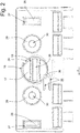
Fig. 1 eine partielle Diagonalansicht einer Welle sowie der Aufhängung eines Rollladenpanzers, -
Fig. 2 eine vergrößerte Darstellung eines in derFig. 1 dargestellten Endglieds einer Aufhängung im nicht verriegelten Zustand, -
Fig. 3 eine rückwärtige Teilansicht der Welle nebst Aufhängung gemäßFig. 1 , -
Fig. 4 eine Draufsicht auf das Endglied in der verriegelten Stellung, -
Fig. 5 eine rückwärtige Ansicht einer Welle nebst Aufhängung in der verriegelten Stellung, -
Fig. 6 eine Längsschnittdarstellung des Endglieds gemäß Schnittlinie VI VI inFig. 4 , -
Fig. 7 eine perspektivische Darstellung des rotativen Betätigungselements und -
Fig. 8 eine Unteransicht des inFig. 7 dargestellten rotativen Betätigungselements.
-
Fig. 1 a partial diagonal view of a shaft and the suspension of a roller shutter, -
Fig. 2 an enlarged view of one in theFig. 1 illustrated end member of a suspension in the unlocked state, -
Fig. 3 a rear partial view of the shaft and suspension according toFig. 1 . -
Fig. 4 a plan view of the end member in the locked position, -
Fig. 5 a rear view of a shaft and suspension in the locked position, -
Fig. 6 a longitudinal sectional view of the end member according to section line VI VI inFig. 4 . -
Fig. 7 a perspective view of the rotary actuator and -
Fig. 8 a bottom view of the inFig. 7 shown rotary actuator.
In den Zeichnungen ist eine Vorrichtung zur Sicherung der Rollläden und Rolltore an eine Welle 11 insgesamt mit der Bezugsziffer 10 bezeichnet.In the drawings, a device for securing the shutters and rolling doors to a
Die Vorrichtung 10 (s.
Die Zwischenglieder 12 und das Endglied 13 sind untereinander gelenkig verbunden. Während das zum Rollladenpanzer weisende Zwischenglied 12 auf das letzte zur Welle 11 weisende Rollladenprofil seitlich, formschlüssig aufgeschoben wird, weist das zur Befestigung an der Welle 11 vorgesehene Endglied 13 eine spezielle lösbare Befestigungseinrichtung 14 auf, die Ausnehmungen 15 der Welle 11 hintergreift.The
In der
Letztlich weist die Betätigungsplatte 18 des rotativen Betätigungselements 17 an ihrem Umfang zwei Aussparungen 23 auf, die den Drehbewegungsspielraum des rotativen Betätigungselements 17 im Endglied 13 definieren.Finally, the
Wie in der
Bei der Montage des rotativen Betätigungselementes 17 im Endglied 13 hintergreift der Rand der Betätigungsplatte 18 einerseits den kleinen Vorsprung 24 und andererseits rastet das rotative Betätigungselement 17 im Bereich der Federlasche 26 in eine drehbare Endposition innerhalb des Endglieds 13 ein.When mounting the
Beidseitig des rotativen Betätigungselements 17 weist das Endglied 13 an den Außenkanten jeweils eine fensterartige Öffnung 27 auf, wobei der fensterartigen Öffnung 27 zur Welle 11 weisend gegenüberliegend an der Unterseite des Endglieds 13 jeweils ein Verriegelungshaken 28 angeformt ist, deren Haken sich gleichsinnig in x-Richtung erstrecken. Zwischen den fensterartigen Öffnungen 27 und dem rotativen Betätigungselement 17 ist letztlich jeweils auch eine Einsenkung 29 mit einer Bohrung 30 angeordnet, welche die Möglichkeit eröffnen, grundsätzlich auch die Vorrichtung 10 mittels einfacher Befestigungsmittel an der Welle 11 anzuordnen.On both sides of the
In der
In der
Den Verriegelungszustand, also das Hintergreifen der Wandung der Welle 11 durch die Verriegelungshaken 22, 28, erkennt man zum einen in der
- 1010
- Vorrichtungcontraption
- 1111
- Wellewave
- 1212
- Zwischengliederbetween members
- 1313
- Endgliedend link
- 1414
- Befestigungseinrichtungfastening device
- 1515
-
Ausnehmung der Welle 11Recess of the
shaft 11 - 1616
- Ausnehmung im Endglied 13Recess in the end member 13th
- 1717
- rotatives Betätigungselementrotary actuator
- 1818
- Betätigungsplatteoperating plate
- 1919
- Vorsprunghead Start
- 2020
- Betätigungsschlitzactuating slot
- 2121
- exzentrischer Vorsprungeccentric projection
- 2222
- Verriegelungshakenlocking hook
- 2323
- Aussparungen in der Umfangsfläche der BetätigungsplatteRecesses in the peripheral surface of the actuator plate
- 2424
- kleiner Vorsprungsmall lead
- 2525
- Ausnehmungrecess
- 2626
- Federlaschespring shackle
- 2727
- fensterartige Öffnungwindow-like opening
- 2828
- Verriegelungshakenlocking hook
- 2929
- Einsenkungdepression
- 3030
- Bohrungdrilling
Claims (8)
Priority Applications (1)
| Application Number | Priority Date | Filing Date | Title |
|---|---|---|---|
| PL17156617T PL3211172T3 (en) | 2016-02-25 | 2017-02-17 | Device for securing roller shutters and roller doors |
Applications Claiming Priority (1)
| Application Number | Priority Date | Filing Date | Title |
|---|---|---|---|
| DE102016103305.7A DE102016103305B3 (en) | 2016-02-25 | 2016-02-25 | Device for securing roller shutters and roller shutters |
Publications (3)
| Publication Number | Publication Date |
|---|---|
| EP3211172A1 true EP3211172A1 (en) | 2017-08-30 |
| EP3211172B1 EP3211172B1 (en) | 2018-07-18 |
| EP3211172B8 EP3211172B8 (en) | 2018-10-24 |
Family
ID=58057014
Family Applications (1)
| Application Number | Title | Priority Date | Filing Date |
|---|---|---|---|
| EP17156617.7A Active EP3211172B8 (en) | 2016-02-25 | 2017-02-17 | Device for securing roller shutters and roller doors |
Country Status (3)
| Country | Link |
|---|---|
| EP (1) | EP3211172B8 (en) |
| DE (1) | DE102016103305B3 (en) |
| PL (1) | PL3211172T3 (en) |
Families Citing this family (1)
| Publication number | Priority date | Publication date | Assignee | Title |
|---|---|---|---|---|
| DE102022112976A1 (en) * | 2022-05-23 | 2023-11-23 | Selve Vermögensverwaltung GmbH & Co. KG | Device for securing roller shutters and roller doors |
Citations (1)
| Publication number | Priority date | Publication date | Assignee | Title |
|---|---|---|---|---|
| EP2589742B1 (en) | 2011-10-21 | 2013-12-04 | SELVE Vermögensverwaltung GmbH & Co. KG | Device for securing roller blinds and roller doors |
Family Cites Families (2)
| Publication number | Priority date | Publication date | Assignee | Title |
|---|---|---|---|---|
| FR2821113B1 (en) * | 2001-02-20 | 2003-09-26 | Deprat Jean Sa | ANTI-LIFT TIE FOR SHUTTERS |
| EA027412B1 (en) * | 2013-12-19 | 2017-07-31 | Общество С Ограниченной Ответственностью "Алютех Инкорпорейтед" | Device for connection of a roll-down shutter to a shaft |
-
2016
- 2016-02-25 DE DE102016103305.7A patent/DE102016103305B3/en not_active Expired - Fee Related
-
2017
- 2017-02-17 EP EP17156617.7A patent/EP3211172B8/en active Active
- 2017-02-17 PL PL17156617T patent/PL3211172T3/en unknown
Patent Citations (1)
| Publication number | Priority date | Publication date | Assignee | Title |
|---|---|---|---|---|
| EP2589742B1 (en) | 2011-10-21 | 2013-12-04 | SELVE Vermögensverwaltung GmbH & Co. KG | Device for securing roller blinds and roller doors |
Also Published As
| Publication number | Publication date |
|---|---|
| EP3211172B8 (en) | 2018-10-24 |
| PL3211172T3 (en) | 2018-12-31 |
| EP3211172B1 (en) | 2018-07-18 |
| DE102016103305B3 (en) | 2017-04-13 |
Similar Documents
| Publication | Publication Date | Title |
|---|---|---|
| EP2873792B1 (en) | Hinges | |
| DE2808057C2 (en) | Grate covering for mechanically moved step-shaped furnace grates of large furnaces | |
| EP2875199B1 (en) | Guide for espagnolette bar | |
| DE69909153T2 (en) | Automatic lock for blinds | |
| EP3684223B1 (en) | Coupling device for drawer with subsequent latching | |
| CH633344A5 (en) | FIXING THE SLATS OF A SLATER BLINDS TO A FLEXIBLE SUPPORTING ELEMENT. | |
| WO2008083865A1 (en) | Lock furniture, and lock furniture set | |
| DE102015004515A1 (en) | fastening device | |
| EP2546438B1 (en) | Fitting part intended for mobile assembly in a fitting groove comprising an undercut | |
| DE3618973C2 (en) | ||
| EP3326249B1 (en) | Arrangement comprising a roof system and a fastening system for the fastening of the roof system on the roof of an electrical cabinet | |
| EP3211172B1 (en) | Device for securing roller shutters and roller doors | |
| EP0616108B1 (en) | Venetian blind | |
| EP2784248B1 (en) | Drive unit for a fitting on a connecting rod | |
| DE102019114332A1 (en) | Lock device | |
| DE202016100985U1 (en) | Device for securing roller shutters and roller shutters | |
| WO2008151697A1 (en) | Fastener for detachably connecting a profile to a counterprofile | |
| EP1777363B1 (en) | Stop device for a door of a housing | |
| EP0685373B1 (en) | Adjustable shoulder anchorage for a vehicle seat belt system | |
| DE102011078754B4 (en) | Hinge with two relative to each other about a common axis of rotation rotatable spring-biased hinge parts | |
| DE102022112968B3 (en) | Device for securing roller shutters and roller doors | |
| EP2149658B1 (en) | Self-adjusting twistlock for an espagnolette locking device | |
| EP1216336B1 (en) | Armature component | |
| EP1213436B1 (en) | Device for connecting a roller shutter to a roller | |
| DE1908478B2 (en) | Swing and tilt window or door drive rods - have engaging serrations in slot side and on second shank counter-piece |
Legal Events
| Date | Code | Title | Description |
|---|---|---|---|
| PUAI | Public reference made under article 153(3) epc to a published international application that has entered the european phase |
Free format text: ORIGINAL CODE: 0009012 |
|
| STAA | Information on the status of an ep patent application or granted ep patent |
Free format text: STATUS: THE APPLICATION HAS BEEN PUBLISHED |
|
| STAA | Information on the status of an ep patent application or granted ep patent |
Free format text: STATUS: REQUEST FOR EXAMINATION WAS MADE |
|
| AK | Designated contracting states |
Kind code of ref document: A1 Designated state(s): AL AT BE BG CH CY CZ DE DK EE ES FI FR GB GR HR HU IE IS IT LI LT LU LV MC MK MT NL NO PL PT RO RS SE SI SK SM TR |
|
| AX | Request for extension of the european patent |
Extension state: BA ME |
|
| 17P | Request for examination filed |
Effective date: 20170809 |
|
| RBV | Designated contracting states (corrected) |
Designated state(s): AL AT BE BG CH CY CZ DE DK EE ES FI FR GB GR HR HU IE IS IT LI LT LU LV MC MK MT NL NO PL PT RO RS SE SI SK SM TR |
|
| GRAP | Despatch of communication of intention to grant a patent |
Free format text: ORIGINAL CODE: EPIDOSNIGR1 |
|
| STAA | Information on the status of an ep patent application or granted ep patent |
Free format text: STATUS: GRANT OF PATENT IS INTENDED |
|
| INTG | Intention to grant announced |
Effective date: 20180226 |
|
| GRAS | Grant fee paid |
Free format text: ORIGINAL CODE: EPIDOSNIGR3 |
|
| GRAA | (expected) grant |
Free format text: ORIGINAL CODE: 0009210 |
|
| STAA | Information on the status of an ep patent application or granted ep patent |
Free format text: STATUS: THE PATENT HAS BEEN GRANTED |
|
| GRAT | Correction requested after decision to grant or after decision to maintain patent in amended form |
Free format text: ORIGINAL CODE: EPIDOSNCDEC |
|
| AK | Designated contracting states |
Kind code of ref document: B1 Designated state(s): AL AT BE BG CH CY CZ DE DK EE ES FI FR GB GR HR HU IE IS IT LI LT LU LV MC MK MT NL NO PL PT RO RS SE SI SK SM TR |
|
| REG | Reference to a national code |
Ref country code: GB Ref legal event code: FG4D Free format text: NOT ENGLISH |
|
| REG | Reference to a national code |
Ref country code: CH Ref legal event code: EP |
|
| REG | Reference to a national code |
Ref country code: IE Ref legal event code: FG4D Free format text: LANGUAGE OF EP DOCUMENT: GERMAN |
|
| RAP2 | Party data changed (patent owner data changed or rights of a patent transferred) |
Owner name: SELVE VERMOEGENSVERWALTUNG GMBH & CO. KG |
|
| REG | Reference to a national code |
Ref country code: AT Ref legal event code: REF Ref document number: 1019555 Country of ref document: AT Kind code of ref document: T Effective date: 20180815 |
|
| REG | Reference to a national code |
Ref country code: DE Ref legal event code: R096 Ref document number: 502017000076 Country of ref document: DE |
|
| REG | Reference to a national code |
Ref country code: CH Ref legal event code: PK Free format text: BERICHTIGUNG B8 |
|
| REG | Reference to a national code |
Ref country code: NL Ref legal event code: FP |
|
| REG | Reference to a national code |
Ref country code: LT Ref legal event code: MG4D |
|
| PG25 | Lapsed in a contracting state [announced via postgrant information from national office to epo] |
Ref country code: LT Free format text: LAPSE BECAUSE OF FAILURE TO SUBMIT A TRANSLATION OF THE DESCRIPTION OR TO PAY THE FEE WITHIN THE PRESCRIBED TIME-LIMIT Effective date: 20180718 Ref country code: FI Free format text: LAPSE BECAUSE OF FAILURE TO SUBMIT A TRANSLATION OF THE DESCRIPTION OR TO PAY THE FEE WITHIN THE PRESCRIBED TIME-LIMIT Effective date: 20180718 Ref country code: BG Free format text: LAPSE BECAUSE OF FAILURE TO SUBMIT A TRANSLATION OF THE DESCRIPTION OR TO PAY THE FEE WITHIN THE PRESCRIBED TIME-LIMIT Effective date: 20181018 Ref country code: SE Free format text: LAPSE BECAUSE OF FAILURE TO SUBMIT A TRANSLATION OF THE DESCRIPTION OR TO PAY THE FEE WITHIN THE PRESCRIBED TIME-LIMIT Effective date: 20180718 Ref country code: GR Free format text: LAPSE BECAUSE OF FAILURE TO SUBMIT A TRANSLATION OF THE DESCRIPTION OR TO PAY THE FEE WITHIN THE PRESCRIBED TIME-LIMIT Effective date: 20181019 Ref country code: IS Free format text: LAPSE BECAUSE OF FAILURE TO SUBMIT A TRANSLATION OF THE DESCRIPTION OR TO PAY THE FEE WITHIN THE PRESCRIBED TIME-LIMIT Effective date: 20181118 Ref country code: RS Free format text: LAPSE BECAUSE OF FAILURE TO SUBMIT A TRANSLATION OF THE DESCRIPTION OR TO PAY THE FEE WITHIN THE PRESCRIBED TIME-LIMIT Effective date: 20180718 Ref country code: NO Free format text: LAPSE BECAUSE OF FAILURE TO SUBMIT A TRANSLATION OF THE DESCRIPTION OR TO PAY THE FEE WITHIN THE PRESCRIBED TIME-LIMIT Effective date: 20181018 |
|
| PG25 | Lapsed in a contracting state [announced via postgrant information from national office to epo] |
Ref country code: LV Free format text: LAPSE BECAUSE OF FAILURE TO SUBMIT A TRANSLATION OF THE DESCRIPTION OR TO PAY THE FEE WITHIN THE PRESCRIBED TIME-LIMIT Effective date: 20180718 Ref country code: AL Free format text: LAPSE BECAUSE OF FAILURE TO SUBMIT A TRANSLATION OF THE DESCRIPTION OR TO PAY THE FEE WITHIN THE PRESCRIBED TIME-LIMIT Effective date: 20180718 Ref country code: HR Free format text: LAPSE BECAUSE OF FAILURE TO SUBMIT A TRANSLATION OF THE DESCRIPTION OR TO PAY THE FEE WITHIN THE PRESCRIBED TIME-LIMIT Effective date: 20180718 |
|
| REG | Reference to a national code |
Ref country code: DE Ref legal event code: R097 Ref document number: 502017000076 Country of ref document: DE |
|
| PG25 | Lapsed in a contracting state [announced via postgrant information from national office to epo] |
Ref country code: CZ Free format text: LAPSE BECAUSE OF FAILURE TO SUBMIT A TRANSLATION OF THE DESCRIPTION OR TO PAY THE FEE WITHIN THE PRESCRIBED TIME-LIMIT Effective date: 20180718 Ref country code: RO Free format text: LAPSE BECAUSE OF FAILURE TO SUBMIT A TRANSLATION OF THE DESCRIPTION OR TO PAY THE FEE WITHIN THE PRESCRIBED TIME-LIMIT Effective date: 20180718 Ref country code: ES Free format text: LAPSE BECAUSE OF FAILURE TO SUBMIT A TRANSLATION OF THE DESCRIPTION OR TO PAY THE FEE WITHIN THE PRESCRIBED TIME-LIMIT Effective date: 20180718 Ref country code: IT Free format text: LAPSE BECAUSE OF FAILURE TO SUBMIT A TRANSLATION OF THE DESCRIPTION OR TO PAY THE FEE WITHIN THE PRESCRIBED TIME-LIMIT Effective date: 20180718 Ref country code: EE Free format text: LAPSE BECAUSE OF FAILURE TO SUBMIT A TRANSLATION OF THE DESCRIPTION OR TO PAY THE FEE WITHIN THE PRESCRIBED TIME-LIMIT Effective date: 20180718 |
|
| PLBE | No opposition filed within time limit |
Free format text: ORIGINAL CODE: 0009261 |
|
| STAA | Information on the status of an ep patent application or granted ep patent |
Free format text: STATUS: NO OPPOSITION FILED WITHIN TIME LIMIT |
|
| PG25 | Lapsed in a contracting state [announced via postgrant information from national office to epo] |
Ref country code: DK Free format text: LAPSE BECAUSE OF FAILURE TO SUBMIT A TRANSLATION OF THE DESCRIPTION OR TO PAY THE FEE WITHIN THE PRESCRIBED TIME-LIMIT Effective date: 20180718 Ref country code: SM Free format text: LAPSE BECAUSE OF FAILURE TO SUBMIT A TRANSLATION OF THE DESCRIPTION OR TO PAY THE FEE WITHIN THE PRESCRIBED TIME-LIMIT Effective date: 20180718 Ref country code: SK Free format text: LAPSE BECAUSE OF FAILURE TO SUBMIT A TRANSLATION OF THE DESCRIPTION OR TO PAY THE FEE WITHIN THE PRESCRIBED TIME-LIMIT Effective date: 20180718 |
|
| 26N | No opposition filed |
Effective date: 20190423 |
|
| PG25 | Lapsed in a contracting state [announced via postgrant information from national office to epo] |
Ref country code: SI Free format text: LAPSE BECAUSE OF FAILURE TO SUBMIT A TRANSLATION OF THE DESCRIPTION OR TO PAY THE FEE WITHIN THE PRESCRIBED TIME-LIMIT Effective date: 20180718 |
|
| PG25 | Lapsed in a contracting state [announced via postgrant information from national office to epo] |
Ref country code: MC Free format text: LAPSE BECAUSE OF FAILURE TO SUBMIT A TRANSLATION OF THE DESCRIPTION OR TO PAY THE FEE WITHIN THE PRESCRIBED TIME-LIMIT Effective date: 20180718 Ref country code: LU Free format text: LAPSE BECAUSE OF NON-PAYMENT OF DUE FEES Effective date: 20190217 |
|
| REG | Reference to a national code |
Ref country code: IE Ref legal event code: MM4A |
|
| PG25 | Lapsed in a contracting state [announced via postgrant information from national office to epo] |
Ref country code: IE Free format text: LAPSE BECAUSE OF NON-PAYMENT OF DUE FEES Effective date: 20190217 |
|
| PG25 | Lapsed in a contracting state [announced via postgrant information from national office to epo] |
Ref country code: TR Free format text: LAPSE BECAUSE OF FAILURE TO SUBMIT A TRANSLATION OF THE DESCRIPTION OR TO PAY THE FEE WITHIN THE PRESCRIBED TIME-LIMIT Effective date: 20180718 |
|
| PG25 | Lapsed in a contracting state [announced via postgrant information from national office to epo] |
Ref country code: PT Free format text: LAPSE BECAUSE OF FAILURE TO SUBMIT A TRANSLATION OF THE DESCRIPTION OR TO PAY THE FEE WITHIN THE PRESCRIBED TIME-LIMIT Effective date: 20181118 Ref country code: MT Free format text: LAPSE BECAUSE OF FAILURE TO SUBMIT A TRANSLATION OF THE DESCRIPTION OR TO PAY THE FEE WITHIN THE PRESCRIBED TIME-LIMIT Effective date: 20180718 |
|
| REG | Reference to a national code |
Ref country code: CH Ref legal event code: PL |
|
| PG25 | Lapsed in a contracting state [announced via postgrant information from national office to epo] |
Ref country code: LI Free format text: LAPSE BECAUSE OF NON-PAYMENT OF DUE FEES Effective date: 20200229 Ref country code: CH Free format text: LAPSE BECAUSE OF NON-PAYMENT OF DUE FEES Effective date: 20200229 |
|
| PG25 | Lapsed in a contracting state [announced via postgrant information from national office to epo] |
Ref country code: CY Free format text: LAPSE BECAUSE OF FAILURE TO SUBMIT A TRANSLATION OF THE DESCRIPTION OR TO PAY THE FEE WITHIN THE PRESCRIBED TIME-LIMIT Effective date: 20180718 |
|
| PG25 | Lapsed in a contracting state [announced via postgrant information from national office to epo] |
Ref country code: HU Free format text: LAPSE BECAUSE OF FAILURE TO SUBMIT A TRANSLATION OF THE DESCRIPTION OR TO PAY THE FEE WITHIN THE PRESCRIBED TIME-LIMIT; INVALID AB INITIO Effective date: 20170217 |
|
| GBPC | Gb: european patent ceased through non-payment of renewal fee |
Effective date: 20210217 |
|
| PG25 | Lapsed in a contracting state [announced via postgrant information from national office to epo] |
Ref country code: GB Free format text: LAPSE BECAUSE OF NON-PAYMENT OF DUE FEES Effective date: 20210217 |
|
| PG25 | Lapsed in a contracting state [announced via postgrant information from national office to epo] |
Ref country code: MK Free format text: LAPSE BECAUSE OF FAILURE TO SUBMIT A TRANSLATION OF THE DESCRIPTION OR TO PAY THE FEE WITHIN THE PRESCRIBED TIME-LIMIT Effective date: 20180718 |
|
| PGFP | Annual fee paid to national office [announced via postgrant information from national office to epo] |
Ref country code: FR Payment date: 20230217 Year of fee payment: 7 |
|
| PGFP | Annual fee paid to national office [announced via postgrant information from national office to epo] |
Ref country code: PL Payment date: 20230118 Year of fee payment: 7 Ref country code: BE Payment date: 20230220 Year of fee payment: 7 |
|
| P01 | Opt-out of the competence of the unified patent court (upc) registered |
Effective date: 20230516 |
|
| P02 | Opt-out of the competence of the unified patent court (upc) changed |
Effective date: 20230517 |
|
| PGFP | Annual fee paid to national office [announced via postgrant information from national office to epo] |
Ref country code: NL Payment date: 20240220 Year of fee payment: 8 |
|
| PGFP | Annual fee paid to national office [announced via postgrant information from national office to epo] |
Ref country code: AT Payment date: 20240216 Year of fee payment: 8 |
|
| PGFP | Annual fee paid to national office [announced via postgrant information from national office to epo] |
Ref country code: DE Payment date: 20240130 Year of fee payment: 8 |