EP3210681A1 - Dispositif et procédé de laminage de matériau en bande à épaisseur variable - Google Patents
Dispositif et procédé de laminage de matériau en bande à épaisseur variable Download PDFInfo
- Publication number
- EP3210681A1 EP3210681A1 EP17155391.0A EP17155391A EP3210681A1 EP 3210681 A1 EP3210681 A1 EP 3210681A1 EP 17155391 A EP17155391 A EP 17155391A EP 3210681 A1 EP3210681 A1 EP 3210681A1
- Authority
- EP
- European Patent Office
- Prior art keywords
- roll
- rollers
- strip material
- dipping
- rolling
- Prior art date
- Legal status (The legal status is an assumption and is not a legal conclusion. Google has not performed a legal analysis and makes no representation as to the accuracy of the status listed.)
- Granted
Links
- 238000005096 rolling process Methods 0.000 title claims abstract description 55
- 239000000463 material Substances 0.000 title claims abstract description 49
- 238000000034 method Methods 0.000 title claims description 12
- 238000007598 dipping method Methods 0.000 claims abstract description 54
- 238000001514 detection method Methods 0.000 claims description 12
- 238000012806 monitoring device Methods 0.000 claims description 8
- 230000001105 regulatory effect Effects 0.000 claims description 2
- 238000007654 immersion Methods 0.000 claims 2
- 238000004804 winding Methods 0.000 abstract description 2
- 230000001133 acceleration Effects 0.000 description 3
- 238000012937 correction Methods 0.000 description 2
- 230000009189 diving Effects 0.000 description 2
- 229910000831 Steel Inorganic materials 0.000 description 1
- 230000006978 adaptation Effects 0.000 description 1
- 230000002950 deficient Effects 0.000 description 1
- 239000002184 metal Substances 0.000 description 1
- 230000000737 periodic effect Effects 0.000 description 1
- 230000002093 peripheral effect Effects 0.000 description 1
- 239000010959 steel Substances 0.000 description 1
- 238000011144 upstream manufacturing Methods 0.000 description 1
Images


Classifications
-
- B—PERFORMING OPERATIONS; TRANSPORTING
- B21—MECHANICAL METAL-WORKING WITHOUT ESSENTIALLY REMOVING MATERIAL; PUNCHING METAL
- B21B—ROLLING OF METAL
- B21B38/00—Methods or devices for measuring, detecting or monitoring specially adapted for metal-rolling mills, e.g. position detection, inspection of the product
- B21B38/10—Methods or devices for measuring, detecting or monitoring specially adapted for metal-rolling mills, e.g. position detection, inspection of the product for measuring roll-gap, e.g. pass indicators
-
- B—PERFORMING OPERATIONS; TRANSPORTING
- B21—MECHANICAL METAL-WORKING WITHOUT ESSENTIALLY REMOVING MATERIAL; PUNCHING METAL
- B21B—ROLLING OF METAL
- B21B1/00—Metal-rolling methods or mills for making semi-finished products of solid or profiled cross-section; Sequence of operations in milling trains; Layout of rolling-mill plant, e.g. grouping of stands; Succession of passes or of sectional pass alternations
- B21B1/22—Metal-rolling methods or mills for making semi-finished products of solid or profiled cross-section; Sequence of operations in milling trains; Layout of rolling-mill plant, e.g. grouping of stands; Succession of passes or of sectional pass alternations for rolling plates, strips, bands or sheets of indefinite length
-
- B—PERFORMING OPERATIONS; TRANSPORTING
- B21—MECHANICAL METAL-WORKING WITHOUT ESSENTIALLY REMOVING MATERIAL; PUNCHING METAL
- B21B—ROLLING OF METAL
- B21B37/00—Control devices or methods specially adapted for metal-rolling mills or the work produced thereby
- B21B37/16—Control of thickness, width, diameter or other transverse dimensions
- B21B37/24—Automatic variation of thickness according to a predetermined programme
- B21B37/26—Automatic variation of thickness according to a predetermined programme for obtaining one strip having successive lengths of different constant thickness
-
- B—PERFORMING OPERATIONS; TRANSPORTING
- B21—MECHANICAL METAL-WORKING WITHOUT ESSENTIALLY REMOVING MATERIAL; PUNCHING METAL
- B21B—ROLLING OF METAL
- B21B37/00—Control devices or methods specially adapted for metal-rolling mills or the work produced thereby
- B21B37/48—Tension control; Compression control
- B21B37/50—Tension control; Compression control by looper control
-
- B—PERFORMING OPERATIONS; TRANSPORTING
- B21—MECHANICAL METAL-WORKING WITHOUT ESSENTIALLY REMOVING MATERIAL; PUNCHING METAL
- B21B—ROLLING OF METAL
- B21B37/00—Control devices or methods specially adapted for metal-rolling mills or the work produced thereby
- B21B37/48—Tension control; Compression control
- B21B37/52—Tension control; Compression control by drive motor control
- B21B37/54—Tension control; Compression control by drive motor control including coiler drive control, e.g. reversing mills
-
- B—PERFORMING OPERATIONS; TRANSPORTING
- B21—MECHANICAL METAL-WORKING WITHOUT ESSENTIALLY REMOVING MATERIAL; PUNCHING METAL
- B21B—ROLLING OF METAL
- B21B2261/00—Product parameters
- B21B2261/02—Transverse dimensions
- B21B2261/04—Thickness, gauge
- B21B2261/05—Different constant thicknesses in one rolled product
-
- B—PERFORMING OPERATIONS; TRANSPORTING
- B21—MECHANICAL METAL-WORKING WITHOUT ESSENTIALLY REMOVING MATERIAL; PUNCHING METAL
- B21B—ROLLING OF METAL
- B21B2265/00—Forming parameters
- B21B2265/02—Tension
- B21B2265/08—Back or outlet tension
Definitions
- the invention relates to a device for rolling strip material with periodically varying strip thickness, wherein the apparatus comprises a roll stand with a set of rollers and a Anstellsystem for adjusting the roll gap of the set of rolls, which roll gap, the strip material is fed with an output thickness on the input side of a spool and from which from the strip material with the respective desired final thickness on the output side of a reel is supplied.
- the invention relates to a method for operating a device for rolling strip material with periodically varying strip thickness
- the apparatus comprises a roll stand with a set of rollers and a Anstellsystem for adjusting the roll gap of the set of rollers, wherein the roll gap, the strip material with an output thickness on the input side of a Uncoiler is supplied from and from which the strip material with the respective desired, by the Walzspalt certain end thickness on the output side of a coiler is supplied.
- a device of the generic type and a method of the generic type are known in the art.
- strip materials are processed from steel strip material.
- EP 1 121 990 B2 a generic device known.
- a possibility is shown in the prior art, with the wound in an economic manner to coils wound metal strips under train, reduced in thickness and then wound up again under train, wherein on the inlet side, a relatively constant strip thickness is provided and a periodic variable strip thickness to be achieved on the outlet side.
- the present invention seeks to provide an alternative solution for a corresponding device or a corresponding method available, the or the features of the force control of a balance or dancer role and a speed control of the reels no Use makes and achieves a faster automatic adjustment of the roll gap and thus a high quality of a periodically variable band material in adaptation to the high belt speeds, taking into account the different belt speeds at the inlet and outlet of the roll gap.
- the invention proposes that both between the reel and the rolling stand and between the rolling stand and the coiler, a roller assembly is arranged with a dipping roll around which the strip material is guided, and that the dipping rolls at a constant roll speed of the nip determining rollers of the roll stand in dependence on the employment of Rolls are position controlled to compensate for the changes in speed of the rolling stock at the inlet and at the outlet of the rolling stand, and that the uncoiler and the coiler are operated zuggeregelt.
- the dipping rollers are position-controlled directly by the adjustment of the nip, which results in a result in a significantly faster correct setting with changing nips and to an exact rolling result.
- both the uncoiler and the coiler operated zuggeregelt which is particularly advantageous for the use of the device.
- each support roll for the strip material is arranged, over which the strip material is guided, and that each support roll has a strip length detection device and / or a belt speed monitoring device.
- the uncoiler and the coiler are provided with a tension measuring device, by means of which the power supply to the drive motors of the reels can be regulated.
- a machine control which detects the employment of the rollers for a predeterminable nip and by means of which the dipping rollers are position-controllable in dependence thereon.
- the rolls of the rolling stand which determine the roll gap circulate at a constant roll speed.
- a method according to the invention is characterized in that both between the uncoiler and the rolling stand and between the rolling stand and the coiler a roller arrangement is arranged with a transverse adjustable to the direction of the strip material dipping roller around which the strip material is guided, wherein the dipping rollers in dependence the position of the rolls of the rolling stand are position-controlled, so that are compensated by the change in position speed changes of the rolling stock at the inlet and at the outlet of the rolling stand, and that the uncoiler and the coiler are operated zugeregelt.
- the strip length and the speed of the continuous strip material are detected in front of and behind each dipping roller and fed to a controller for the rolling mill Position detection and / or correction of the position of the dipping rollers are generated.
- the tensile forces of the reels detected and the data collected are fed to a control device by means of which the power supply to the drive systems of the reels is controlled such that the reel train adapted in each case to the requirements of the operating parameters becomes.
- the setting of the rollers for a predetermined roll gap detected and these are supplied as signals of a control device by means of which the dipping rollers are placed in a roll gap associated in the control as a data pattern stored target movement.
- the rolls of the roll stand determining the roll gap are operated at a constant roll speed.
- FIG. 1 In general, a device according to the invention for rolling strip material 1 with periodically variable strip thickness is shown.
- the device is shown schematically in side view.
- the direction of passage of the strip material is indicated at 2.
- the apparatus comprises a roll stand 3, of which the essential components, namely a roll set with two rolls 4 and 5 is shown.
- a positioning system 6 is shown schematically, which is designed to adjust the roll gap of the set of rollers 4, 5.
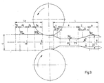
- the nip in particular in FIG. 2 and 3 is clearly visible, is set according to the desired band thickness to be generated.
- the strip gap 1 the strip material is fed with an initial thickness on the input side of a take-off reel 7 and from the nip of the strip material 1 with the respective desired final thickness on the output side of a reel 8 is supplied.
- a roller assembly with at least one dipping roller 9 and 10 is arranged.
- tape guide rollers 13, 14, 15, 16 are arranged, wherein between the guide roller 13 and the take-off reel 7 another guide and guide roller 17 and also between the guide roller 16 and the coiler 8 another guide and guide roller 18th arranged.
- the continuous strip material 1 is guided around the rollers 17, 13, 9, 14 and 15, 10, 16, 18, respectively.
- the dipping rollers are seen by means of an actuator 19 and 20 in the direction of the movement arrows 11 and 12 up or down in the plane of the drawing adjustable and are at constant roller speed of the roll gap determining rollers 4, 5 of the roll stand 3 in dependence on the Positioning of the rollers 4, 5 controlled to compensate for the changes in speed of the rolling stock, ie the strip material 1, at the inlet and at the outlet of the roll stand 3.
- the uncoiler 7 and the reel 8 are operated zuggeregelt.
- each dipping roller 9 and behind each dipping roll 10 arranged support rollers 13, 14 and 15, 16, over which the strip material 1 is guided each have a tape length detection device and a belt speed monitoring device 21, 22 and 23, 24.
- the uncoiler 7 and the coiler 8 are each provided with a tension measuring device ZM, by means of which the power supply, which is indicated at 25, 26, to the drive motors MA of the reels 7, 8 is adjustable to the reel train adapted to the requirements of the operating parameters to keep.
- a machine control 27 which detect and process or store the setting values for the setting of the rolls 4, 5 for a predeterminable roll gap and by means of of which the dipping rollers 9, 10 are position-controllable depending thereon.
- the machine control communicates 27 with the Anstellsystem 6, with the tape length detection devices and belt speed monitoring devices 21, 22, 23, 24 with the adjusting devices 19, 20 for the dipping rollers 9, 10, so that by means of the machine control 27, the employment of the rollers 4, 5 for the detected predetermined roll gap and the dipping rollers 9, 10 are position-controlled in dependence thereon.
- roller gap determining rollers 4, 5 of the roll stand 3 are operated at a constant roller speed.
- the entire area from the uncoiler 7 to the rolling mill 3 is referred to as the lead-in area and the area from the rolling stand 3 to the reel 8 as the lead-out area.
- the speed changes of the rolling stock (strip material 1) resulting from the rolling of periodically variable strip thicknesses at a constant roll speed in the inlet and outlet of the roll stand 3 are compensated by the movement of the two dipping rolls 9 and 10.
- the dipping rollers 9, 10 are position-controlled. The control takes place directly from the employment of the rollers 4, 5 in Connection with signals to the rolled strip length.
- the operation of the two reels 7 and 8 is zuggeregelt.
- the aim is to derive the movement of the dipping rollers 9, 10 directly from the operating parameters of the rolling process.
- the direction of movement and the type of movement (constant speed, acceleration or deceleration) of the dipping rollers 9, 10 should be determined by the profile of the rolled material.
- the movement of the dipping rollers 9, 10 takes place periodically.
- Each period of the dipping rollers 9, 10 in the inlet and outlet is assigned to exactly one rolling period.
- the profile of the rolled material of a rolling period L is subdivided into segments.
- the individual segments each comprise areas with constant strip thickness (a with s 1 and b with s 2 ) and with variable strip thickness (Y and Z).
- a cross-sectional By determining the individual cross-sections can always be a segment in the outlet a cross-sectional equal and thus masse Swes segment in the roll inlet are assigned (a E and b E and y E and z E with the input tape thickness s).
- the result for a rolling period L is the mass of the same length in the inlet L E.
- an average band thickness s M in the outlet can be calculated.
- This average strip thickness is equivalent to the average speed in the roll outlet (V AM ) and thus also determines the average speed in the inlet (V EM ).
- the reel speeds in the inlet and outlet then each correspond to these average speeds, as if under constant conditions the incoming strip of thickness s would be rolled down to the thickness s M.
- the movements of the roller adjustment and thus the rolling profile are also decisive for the current speed.
- the infeed speed is higher with a low pass decrease than with a large pass decrease.
- the segments in the outlet can always be cross-sectionally equal segments in the roll inlet assign. From the segments of a complete period, it is then possible to determine both an average speed in the inlet and to determine the movement of the dipping rollers 9, 10 according to segments.
- the segment b is thicker than the average thickness s M with the thickness s 2 .
- a constant upward movement of the dipping roller is required.
- the segment Z is divided into two sections (Z 1 and Z 2 ) by crossing the thickness of the medium-thickness rolled profile. In the area Z 1 , the thickness is reduced to the average thickness. This means that the speed of the outgoing band is accelerated, up to the average speed v AM . At the crossing point, the average speed and the speed of the outgoing band are identical. For the dipping roll this results in that the upward movement of the dipping roll is braked and in the crossing point the roll reaches its top dead center. In the area Z 2 , the thickness continues reduced to the thickness s 1 . The speed of the outgoing belt is accelerated up to the speed v A1 . The dipping roller is accelerated downwards in this area.
- the segment a is thinner than the average thickness s M with the thickness s 1 .
- the speed of the outgoing band v A1 is thus greater than the average speed v AM .
- the dive roller compensates for this by a constant downward movement.
- the speed of the outgoing band is reduced to the speed v A2 .
- the downward movement is slowed down to the bottom dead center and in the area Y 2 the dipping roller is accelerated upward again.
- the control of the dipping roller movement in the inlet follows the dipping roller control of the outlet.
- the dipping roller movement compensates for this and goes upwards in the segment b E at constant speed and also downwards in the segment a E.
- the segments Z E and Y E are also characterized by braking, dead center and acceleration. The dead points are each controlled simultaneously with the outlet-side dead centers.
- the rollers in each case before the inlet and after the exit of a dipping roller are provided with pulse detectors for the detection of the belt lengths and the speed.
- the signals for the dipping roller movement can therefore be matched exactly to the roller adjustment and thus to the rolled section.
- Corrections may be necessary, for example, if during very rapid movements of the roll adjustment, the influence of the roll diameter is so large that the additional in the inlet displaced or released material shares affect the Tauchrollenzi or if thickness deviations of the strip influence the rolling process.
Applications Claiming Priority (1)
| Application Number | Priority Date | Filing Date | Title |
|---|---|---|---|
| DE102016103088 | 2016-02-23 |
Publications (2)
| Publication Number | Publication Date |
|---|---|
| EP3210681A1 true EP3210681A1 (fr) | 2017-08-30 |
| EP3210681B1 EP3210681B1 (fr) | 2020-01-15 |
Family
ID=58009739
Family Applications (1)
| Application Number | Title | Priority Date | Filing Date |
|---|---|---|---|
| EP17155391.0A Active EP3210681B1 (fr) | 2016-02-23 | 2017-02-09 | Dispositif et procédé de laminage de matériau en bande à épaisseur variable |
Country Status (3)
| Country | Link |
|---|---|
| US (1) | US10413949B2 (fr) |
| EP (1) | EP3210681B1 (fr) |
| ES (1) | ES2769264T3 (fr) |
Cited By (3)
| Publication number | Priority date | Publication date | Assignee | Title |
|---|---|---|---|---|
| WO2020114976A1 (fr) * | 2018-12-06 | 2020-06-11 | Sms Group Gmbh | Procédé servant à faire fonctionner une cage de laminoir de laminage à gradins |
| CN112605124A (zh) * | 2020-11-27 | 2021-04-06 | 广州普德机电设备有限公司 | 一种连续变截面薄钢板的轧制设备及成型方法 |
| WO2021175636A1 (fr) * | 2020-03-06 | 2021-09-10 | Sms Group Gmbh | Cage de laminage |
Families Citing this family (4)
| Publication number | Priority date | Publication date | Assignee | Title |
|---|---|---|---|---|
| HUE063023T2 (hu) * | 2016-12-30 | 2023-12-28 | Outokumpu Oy | Eljárás és berendezés fémszalagok rugalmas hengerlésére |
| CN107716550B (zh) * | 2017-09-09 | 2019-03-29 | 首钢集团有限公司 | 一种低合金纵向变厚度钢板的生产方法 |
| JP7135991B2 (ja) * | 2019-04-25 | 2022-09-13 | トヨタ自動車株式会社 | 校正判断装置、及び校正判断方法 |
| BR112022021572A2 (pt) | 2020-05-14 | 2022-12-06 | Nippon Steel Corp | Método para produzir ferro reduzido |
Citations (4)
| Publication number | Priority date | Publication date | Assignee | Title |
|---|---|---|---|---|
| JPH1034204A (ja) * | 1996-07-29 | 1998-02-10 | Kawasaki Steel Corp | 可逆圧延機における張力制御装置 |
| EP1454681A2 (fr) * | 2003-03-07 | 2004-09-08 | Sundwig GmbH | Dispositif et procédé pour le laminage de bandes métalliques |
| EP1908534A1 (fr) * | 2006-10-07 | 2008-04-09 | ACHENBACH BUSCHHÜTTEN GmbH | Laminoir et procédé de laminage flexible à froid ou à chaud à voie unique ou inverse d'une bande de métal |
| EP1121990B2 (fr) | 2000-02-02 | 2012-02-29 | Josef Fröhling GmbH & Co. KG | Dispositif pour le laminage de bandes d'épaisseur variable périodiquement |
-
2017
- 2017-02-09 EP EP17155391.0A patent/EP3210681B1/fr active Active
- 2017-02-09 ES ES17155391T patent/ES2769264T3/es active Active
- 2017-02-21 US US15/438,396 patent/US10413949B2/en active Active
Patent Citations (4)
| Publication number | Priority date | Publication date | Assignee | Title |
|---|---|---|---|---|
| JPH1034204A (ja) * | 1996-07-29 | 1998-02-10 | Kawasaki Steel Corp | 可逆圧延機における張力制御装置 |
| EP1121990B2 (fr) | 2000-02-02 | 2012-02-29 | Josef Fröhling GmbH & Co. KG | Dispositif pour le laminage de bandes d'épaisseur variable périodiquement |
| EP1454681A2 (fr) * | 2003-03-07 | 2004-09-08 | Sundwig GmbH | Dispositif et procédé pour le laminage de bandes métalliques |
| EP1908534A1 (fr) * | 2006-10-07 | 2008-04-09 | ACHENBACH BUSCHHÜTTEN GmbH | Laminoir et procédé de laminage flexible à froid ou à chaud à voie unique ou inverse d'une bande de métal |
Cited By (4)
| Publication number | Priority date | Publication date | Assignee | Title |
|---|---|---|---|---|
| WO2020114976A1 (fr) * | 2018-12-06 | 2020-06-11 | Sms Group Gmbh | Procédé servant à faire fonctionner une cage de laminoir de laminage à gradins |
| WO2021175636A1 (fr) * | 2020-03-06 | 2021-09-10 | Sms Group Gmbh | Cage de laminage |
| CN112605124A (zh) * | 2020-11-27 | 2021-04-06 | 广州普德机电设备有限公司 | 一种连续变截面薄钢板的轧制设备及成型方法 |
| CN112605124B (zh) * | 2020-11-27 | 2022-07-05 | 苏州吉润汽车零部件有限公司 | 一种连续变截面薄钢板的轧制设备及成型方法 |
Also Published As
| Publication number | Publication date |
|---|---|
| US20170239700A1 (en) | 2017-08-24 |
| ES2769264T3 (es) | 2020-06-25 |
| US10413949B2 (en) | 2019-09-17 |
| EP3210681B1 (fr) | 2020-01-15 |
Similar Documents
| Publication | Publication Date | Title |
|---|---|---|
| EP3210681B1 (fr) | Dispositif et procédé de laminage de matériau en bande à épaisseur variable | |
| EP2477764B1 (fr) | Procédé et dispositif pour le dressage par traction et flexion continu de bandes métalliques | |
| EP3584016B1 (fr) | Réduction de l'usure des rouleaux de caisse à rouleaux | |
| EP1784266B1 (fr) | Laminoir destine a laminer une bande metallique | |
| EP2418031A1 (fr) | Procédé de fabrication d'une bande métallique à l'aide d'une installation de laminage par coulée, dispositif de commande et/ou de réglage pour une installation composite de laminage par coulée et installation composite de laminage par coulée | |
| EP1908534B1 (fr) | Laminoir et procédé de laminage flexible à froid ou à chaud à voie unique ou inverse d'une bande de métal | |
| AT410767B (de) | Verfahren und vorrichtung zur kontinuierlichen herstellung eines gewalzten metallbandes aus einermetallschmelze | |
| EP2741870B1 (fr) | Installation de laminage et procédé de laminage | |
| EP2621645B1 (fr) | Procédé de commande d'un train de laminoir tandem, dispositif de commande et/ou de régulation pour un train de laminoir tandem, code de programme lisible par machine, support de stockage et train de laminoir tandem | |
| DE1427888B2 (de) | Einrichtung zur Dickenverringerung von Bandmaterial | |
| EP1121990B2 (fr) | Dispositif pour le laminage de bandes d'épaisseur variable périodiquement | |
| EP3720623B1 (fr) | Système d'étirement, de courbure et de redressement et son procédé d'actionnement | |
| DE2857504C2 (de) | Vorrichtung zur Regelung der Dicke von thermoplastischen Folien | |
| EP0734795B1 (fr) | Procédé pour la régulation à action directe d'épaisseur dans le laminage de feuillards | |
| EP0752285A2 (fr) | Procédé et dispositif de laminage de bandes ayant transversalement des irrégularités d'épaisseur et/ou de longeur | |
| WO2011095265A2 (fr) | Train de laminage à chaud pour le laminage d'un feuillard à chaud, procédé pour faire fonctionner un train de laminage à chaud pour le laminage d'un feuillard à chaud, ainsi que dispositif de commande et/ou de régulation | |
| DE102020117682A1 (de) | Richtmaschine und Verfahren zum Richten eines Metallbandes oder eines flächigen Metallteils | |
| EP1669141B1 (fr) | Procédé pour le réglage de la section des fils sortant d'un train de laminage de fil et train de laminage de fil | |
| EP2283941A1 (fr) | Procédé de commande et/ou de réglage d'un leveur de boucle se trouvant dans une chaîne de laminage, commande et/ou dispositif de réglage pour une chaîne de laminage et chaîne de laminage | |
| DE102018127672A1 (de) | Verfahren für eine Kontrolle eines Randabschnitts einer Folienbahn | |
| EP4103339B1 (fr) | Détermination de la sensibilité d'une grandeur cible d'une matière à laminer pour un paramètre de fonctionnement d'un train de laminage à chaud | |
| EP3873685B1 (fr) | Ligne de laminage | |
| DE102008037520B4 (de) | Vorrichtung und Verfahren zur Herstellung einer Metallfolie | |
| WO2024099701A1 (fr) | Procédé et système d'enroulement | |
| EP2279805A1 (fr) | Procédé de commande et/ou de réglage d'une position d'une bande métallique passant dans une chaîne de laminage, dispositif de commande et/ou de réglage et chaîne de laminage |
Legal Events
| Date | Code | Title | Description |
|---|---|---|---|
| PUAI | Public reference made under article 153(3) epc to a published international application that has entered the european phase |
Free format text: ORIGINAL CODE: 0009012 |
|
| STAA | Information on the status of an ep patent application or granted ep patent |
Free format text: STATUS: THE APPLICATION HAS BEEN PUBLISHED |
|
| AK | Designated contracting states |
Kind code of ref document: A1 Designated state(s): AL AT BE BG CH CY CZ DE DK EE ES FI FR GB GR HR HU IE IS IT LI LT LU LV MC MK MT NL NO PL PT RO RS SE SI SK SM TR |
|
| AX | Request for extension of the european patent |
Extension state: BA ME |
|
| STAA | Information on the status of an ep patent application or granted ep patent |
Free format text: STATUS: REQUEST FOR EXAMINATION WAS MADE |
|
| 17P | Request for examination filed |
Effective date: 20180117 |
|
| RBV | Designated contracting states (corrected) |
Designated state(s): AL AT BE BG CH CY CZ DE DK EE ES FI FR GB GR HR HU IE IS IT LI LT LU LV MC MK MT NL NO PL PT RO RS SE SI SK SM TR |
|
| STAA | Information on the status of an ep patent application or granted ep patent |
Free format text: STATUS: EXAMINATION IS IN PROGRESS |
|
| 17Q | First examination report despatched |
Effective date: 20181108 |
|
| GRAP | Despatch of communication of intention to grant a patent |
Free format text: ORIGINAL CODE: EPIDOSNIGR1 |
|
| STAA | Information on the status of an ep patent application or granted ep patent |
Free format text: STATUS: GRANT OF PATENT IS INTENDED |
|
| INTG | Intention to grant announced |
Effective date: 20190925 |
|
| GRAS | Grant fee paid |
Free format text: ORIGINAL CODE: EPIDOSNIGR3 |
|
| GRAA | (expected) grant |
Free format text: ORIGINAL CODE: 0009210 |
|
| STAA | Information on the status of an ep patent application or granted ep patent |
Free format text: STATUS: THE PATENT HAS BEEN GRANTED |
|
| REG | Reference to a national code |
Ref country code: DE Ref legal event code: R081 Ref document number: 502017003484 Country of ref document: DE Owner name: BILSTEIN GMBH & CO. KG, DE Free format text: FORMER OWNER: BILSTEIN GMBH & CO. KG, 58119 HAGEN, DE |
|
| AK | Designated contracting states |
Kind code of ref document: B1 Designated state(s): AL AT BE BG CH CY CZ DE DK EE ES FI FR GB GR HR HU IE IS IT LI LT LU LV MC MK MT NL NO PL PT RO RS SE SI SK SM TR |
|
| REG | Reference to a national code |
Ref country code: CH Ref legal event code: EP Ref country code: GB Ref legal event code: FG4D Free format text: NOT ENGLISH |
|
| REG | Reference to a national code |
Ref country code: IE Ref legal event code: FG4D Free format text: LANGUAGE OF EP DOCUMENT: GERMAN |
|
| REG | Reference to a national code |
Ref country code: AT Ref legal event code: REF Ref document number: 1224700 Country of ref document: AT Kind code of ref document: T Effective date: 20200215 |
|
| REG | Reference to a national code |
Ref country code: DE Ref legal event code: R096 Ref document number: 502017003484 Country of ref document: DE |
|
| REG | Reference to a national code |
Ref country code: NL Ref legal event code: FP |
|
| REG | Reference to a national code |
Ref country code: SE Ref legal event code: TRGR |
|
| REG | Reference to a national code |
Ref country code: ES Ref legal event code: FG2A Ref document number: 2769264 Country of ref document: ES Kind code of ref document: T3 Effective date: 20200625 |
|
| REG | Reference to a national code |
Ref country code: LT Ref legal event code: MG4D |
|
| PG25 | Lapsed in a contracting state [announced via postgrant information from national office to epo] |
Ref country code: PT Free format text: LAPSE BECAUSE OF FAILURE TO SUBMIT A TRANSLATION OF THE DESCRIPTION OR TO PAY THE FEE WITHIN THE PRESCRIBED TIME-LIMIT Effective date: 20200607 Ref country code: NO Free format text: LAPSE BECAUSE OF FAILURE TO SUBMIT A TRANSLATION OF THE DESCRIPTION OR TO PAY THE FEE WITHIN THE PRESCRIBED TIME-LIMIT Effective date: 20200415 Ref country code: FI Free format text: LAPSE BECAUSE OF FAILURE TO SUBMIT A TRANSLATION OF THE DESCRIPTION OR TO PAY THE FEE WITHIN THE PRESCRIBED TIME-LIMIT Effective date: 20200115 Ref country code: RS Free format text: LAPSE BECAUSE OF FAILURE TO SUBMIT A TRANSLATION OF THE DESCRIPTION OR TO PAY THE FEE WITHIN THE PRESCRIBED TIME-LIMIT Effective date: 20200115 |
|
| PG25 | Lapsed in a contracting state [announced via postgrant information from national office to epo] |
Ref country code: LV Free format text: LAPSE BECAUSE OF FAILURE TO SUBMIT A TRANSLATION OF THE DESCRIPTION OR TO PAY THE FEE WITHIN THE PRESCRIBED TIME-LIMIT Effective date: 20200115 Ref country code: IS Free format text: LAPSE BECAUSE OF FAILURE TO SUBMIT A TRANSLATION OF THE DESCRIPTION OR TO PAY THE FEE WITHIN THE PRESCRIBED TIME-LIMIT Effective date: 20200515 Ref country code: GR Free format text: LAPSE BECAUSE OF FAILURE TO SUBMIT A TRANSLATION OF THE DESCRIPTION OR TO PAY THE FEE WITHIN THE PRESCRIBED TIME-LIMIT Effective date: 20200416 Ref country code: HR Free format text: LAPSE BECAUSE OF FAILURE TO SUBMIT A TRANSLATION OF THE DESCRIPTION OR TO PAY THE FEE WITHIN THE PRESCRIBED TIME-LIMIT Effective date: 20200115 Ref country code: BG Free format text: LAPSE BECAUSE OF FAILURE TO SUBMIT A TRANSLATION OF THE DESCRIPTION OR TO PAY THE FEE WITHIN THE PRESCRIBED TIME-LIMIT Effective date: 20200415 |
|
| REG | Reference to a national code |
Ref country code: CH Ref legal event code: PL |
|
| REG | Reference to a national code |
Ref country code: DE Ref legal event code: R097 Ref document number: 502017003484 Country of ref document: DE |
|
| REG | Reference to a national code |
Ref country code: BE Ref legal event code: MM Effective date: 20200229 |
|
| PG25 | Lapsed in a contracting state [announced via postgrant information from national office to epo] |
Ref country code: LT Free format text: LAPSE BECAUSE OF FAILURE TO SUBMIT A TRANSLATION OF THE DESCRIPTION OR TO PAY THE FEE WITHIN THE PRESCRIBED TIME-LIMIT Effective date: 20200115 Ref country code: EE Free format text: LAPSE BECAUSE OF FAILURE TO SUBMIT A TRANSLATION OF THE DESCRIPTION OR TO PAY THE FEE WITHIN THE PRESCRIBED TIME-LIMIT Effective date: 20200115 Ref country code: SM Free format text: LAPSE BECAUSE OF FAILURE TO SUBMIT A TRANSLATION OF THE DESCRIPTION OR TO PAY THE FEE WITHIN THE PRESCRIBED TIME-LIMIT Effective date: 20200115 Ref country code: LU Free format text: LAPSE BECAUSE OF NON-PAYMENT OF DUE FEES Effective date: 20200209 Ref country code: RO Free format text: LAPSE BECAUSE OF FAILURE TO SUBMIT A TRANSLATION OF THE DESCRIPTION OR TO PAY THE FEE WITHIN THE PRESCRIBED TIME-LIMIT Effective date: 20200115 Ref country code: MC Free format text: LAPSE BECAUSE OF FAILURE TO SUBMIT A TRANSLATION OF THE DESCRIPTION OR TO PAY THE FEE WITHIN THE PRESCRIBED TIME-LIMIT Effective date: 20200115 Ref country code: SK Free format text: LAPSE BECAUSE OF FAILURE TO SUBMIT A TRANSLATION OF THE DESCRIPTION OR TO PAY THE FEE WITHIN THE PRESCRIBED TIME-LIMIT Effective date: 20200115 Ref country code: DK Free format text: LAPSE BECAUSE OF FAILURE TO SUBMIT A TRANSLATION OF THE DESCRIPTION OR TO PAY THE FEE WITHIN THE PRESCRIBED TIME-LIMIT Effective date: 20200115 |
|
| PLBE | No opposition filed within time limit |
Free format text: ORIGINAL CODE: 0009261 |
|
| STAA | Information on the status of an ep patent application or granted ep patent |
Free format text: STATUS: NO OPPOSITION FILED WITHIN TIME LIMIT |
|
| PG25 | Lapsed in a contracting state [announced via postgrant information from national office to epo] |
Ref country code: CH Free format text: LAPSE BECAUSE OF NON-PAYMENT OF DUE FEES Effective date: 20200229 Ref country code: LI Free format text: LAPSE BECAUSE OF NON-PAYMENT OF DUE FEES Effective date: 20200229 |
|
| 26N | No opposition filed |
Effective date: 20201016 |
|
| REG | Reference to a national code |
Ref country code: DE Ref legal event code: R082 Ref document number: 502017003484 Country of ref document: DE Representative=s name: PATENTANWAELTE KOECHLING, DOERING PARTG MBB, DE Ref country code: DE Ref legal event code: R081 Ref document number: 502017003484 Country of ref document: DE Owner name: BILSTEIN GMBH & CO. KG, DE Free format text: FORMER OWNERS: BILSTEIN GMBH & CO. KG, 58119 HAGEN, DE; TILGERT WALZMASCHINENBAU GMBH, 58642 ISERLOHN, DE |
|
| REG | Reference to a national code |
Ref country code: NL Ref legal event code: PD Owner name: BILSTEIN GMBH & CO. KG; DE Free format text: DETAILS ASSIGNMENT: CHANGE OF OWNER(S), ASSIGNMENT; FORMER OWNER NAME: TILGERT WALZWERKSMASCHINENBAU GMBH Effective date: 20210108 |
|
| PG25 | Lapsed in a contracting state [announced via postgrant information from national office to epo] |
Ref country code: IE Free format text: LAPSE BECAUSE OF NON-PAYMENT OF DUE FEES Effective date: 20200209 |
|
| REG | Reference to a national code |
Ref country code: ES Ref legal event code: PC2A Owner name: BILSTEIN GMBH & CO. KG Effective date: 20210216 |
|
| PG25 | Lapsed in a contracting state [announced via postgrant information from national office to epo] |
Ref country code: SI Free format text: LAPSE BECAUSE OF FAILURE TO SUBMIT A TRANSLATION OF THE DESCRIPTION OR TO PAY THE FEE WITHIN THE PRESCRIBED TIME-LIMIT Effective date: 20200115 Ref country code: BE Free format text: LAPSE BECAUSE OF NON-PAYMENT OF DUE FEES Effective date: 20200229 Ref country code: PL Free format text: LAPSE BECAUSE OF FAILURE TO SUBMIT A TRANSLATION OF THE DESCRIPTION OR TO PAY THE FEE WITHIN THE PRESCRIBED TIME-LIMIT Effective date: 20200115 |
|
| REG | Reference to a national code |
Ref country code: GB Ref legal event code: 732E Free format text: REGISTERED BETWEEN 20210211 AND 20210217 |
|
| PG25 | Lapsed in a contracting state [announced via postgrant information from national office to epo] |
Ref country code: MT Free format text: LAPSE BECAUSE OF FAILURE TO SUBMIT A TRANSLATION OF THE DESCRIPTION OR TO PAY THE FEE WITHIN THE PRESCRIBED TIME-LIMIT Effective date: 20200115 Ref country code: CY Free format text: LAPSE BECAUSE OF FAILURE TO SUBMIT A TRANSLATION OF THE DESCRIPTION OR TO PAY THE FEE WITHIN THE PRESCRIBED TIME-LIMIT Effective date: 20200115 |
|
| PG25 | Lapsed in a contracting state [announced via postgrant information from national office to epo] |
Ref country code: MK Free format text: LAPSE BECAUSE OF FAILURE TO SUBMIT A TRANSLATION OF THE DESCRIPTION OR TO PAY THE FEE WITHIN THE PRESCRIBED TIME-LIMIT Effective date: 20200115 Ref country code: AL Free format text: LAPSE BECAUSE OF FAILURE TO SUBMIT A TRANSLATION OF THE DESCRIPTION OR TO PAY THE FEE WITHIN THE PRESCRIBED TIME-LIMIT Effective date: 20200115 |
|
| REG | Reference to a national code |
Ref country code: AT Ref legal event code: MM01 Ref document number: 1224700 Country of ref document: AT Kind code of ref document: T Effective date: 20220209 |
|
| PG25 | Lapsed in a contracting state [announced via postgrant information from national office to epo] |
Ref country code: AT Free format text: LAPSE BECAUSE OF NON-PAYMENT OF DUE FEES Effective date: 20220209 |
|
| PGFP | Annual fee paid to national office [announced via postgrant information from national office to epo] |
Ref country code: FR Payment date: 20230216 Year of fee payment: 7 Ref country code: ES Payment date: 20230317 Year of fee payment: 7 Ref country code: CZ Payment date: 20230130 Year of fee payment: 7 |
|
| PGFP | Annual fee paid to national office [announced via postgrant information from national office to epo] |
Ref country code: TR Payment date: 20230208 Year of fee payment: 7 Ref country code: SE Payment date: 20230216 Year of fee payment: 7 Ref country code: IT Payment date: 20230217 Year of fee payment: 7 Ref country code: GB Payment date: 20230217 Year of fee payment: 7 |
|
| P01 | Opt-out of the competence of the unified patent court (upc) registered |
Effective date: 20230509 |
|
| PGFP | Annual fee paid to national office [announced via postgrant information from national office to epo] |
Ref country code: DE Payment date: 20230502 Year of fee payment: 7 |
|
| PGFP | Annual fee paid to national office [announced via postgrant information from national office to epo] |
Ref country code: NL Payment date: 20240220 Year of fee payment: 8 Ref country code: ES Payment date: 20240319 Year of fee payment: 8 |
|
| PGFP | Annual fee paid to national office [announced via postgrant information from national office to epo] |
Ref country code: CZ Payment date: 20240205 Year of fee payment: 8 Ref country code: GB Payment date: 20240228 Year of fee payment: 8 |