EP3210681A1 - Device and method for rolling a strip of material with variable thickness - Google Patents
Device and method for rolling a strip of material with variable thickness Download PDFInfo
- Publication number
- EP3210681A1 EP3210681A1 EP17155391.0A EP17155391A EP3210681A1 EP 3210681 A1 EP3210681 A1 EP 3210681A1 EP 17155391 A EP17155391 A EP 17155391A EP 3210681 A1 EP3210681 A1 EP 3210681A1
- Authority
- EP
- European Patent Office
- Prior art keywords
- roll
- rollers
- strip material
- dipping
- rolling
- Prior art date
- Legal status (The legal status is an assumption and is not a legal conclusion. Google has not performed a legal analysis and makes no representation as to the accuracy of the status listed.)
- Granted
Links
Images


Classifications
-
- B—PERFORMING OPERATIONS; TRANSPORTING
- B21—MECHANICAL METAL-WORKING WITHOUT ESSENTIALLY REMOVING MATERIAL; PUNCHING METAL
- B21B—ROLLING OF METAL
- B21B38/00—Methods or devices for measuring, detecting or monitoring specially adapted for metal-rolling mills, e.g. position detection, inspection of the product
- B21B38/10—Methods or devices for measuring, detecting or monitoring specially adapted for metal-rolling mills, e.g. position detection, inspection of the product for measuring roll-gap, e.g. pass indicators
-
- B—PERFORMING OPERATIONS; TRANSPORTING
- B21—MECHANICAL METAL-WORKING WITHOUT ESSENTIALLY REMOVING MATERIAL; PUNCHING METAL
- B21B—ROLLING OF METAL
- B21B1/00—Metal-rolling methods or mills for making semi-finished products of solid or profiled cross-section; Sequence of operations in milling trains; Layout of rolling-mill plant, e.g. grouping of stands; Succession of passes or of sectional pass alternations
- B21B1/22—Metal-rolling methods or mills for making semi-finished products of solid or profiled cross-section; Sequence of operations in milling trains; Layout of rolling-mill plant, e.g. grouping of stands; Succession of passes or of sectional pass alternations for rolling plates, strips, bands or sheets of indefinite length
-
- B—PERFORMING OPERATIONS; TRANSPORTING
- B21—MECHANICAL METAL-WORKING WITHOUT ESSENTIALLY REMOVING MATERIAL; PUNCHING METAL
- B21B—ROLLING OF METAL
- B21B37/00—Control devices or methods specially adapted for metal-rolling mills or the work produced thereby
- B21B37/16—Control of thickness, width, diameter or other transverse dimensions
- B21B37/24—Automatic variation of thickness according to a predetermined programme
- B21B37/26—Automatic variation of thickness according to a predetermined programme for obtaining one strip having successive lengths of different constant thickness
-
- B—PERFORMING OPERATIONS; TRANSPORTING
- B21—MECHANICAL METAL-WORKING WITHOUT ESSENTIALLY REMOVING MATERIAL; PUNCHING METAL
- B21B—ROLLING OF METAL
- B21B37/00—Control devices or methods specially adapted for metal-rolling mills or the work produced thereby
- B21B37/48—Tension control; Compression control
- B21B37/50—Tension control; Compression control by looper control
-
- B—PERFORMING OPERATIONS; TRANSPORTING
- B21—MECHANICAL METAL-WORKING WITHOUT ESSENTIALLY REMOVING MATERIAL; PUNCHING METAL
- B21B—ROLLING OF METAL
- B21B37/00—Control devices or methods specially adapted for metal-rolling mills or the work produced thereby
- B21B37/48—Tension control; Compression control
- B21B37/52—Tension control; Compression control by drive motor control
- B21B37/54—Tension control; Compression control by drive motor control including coiler drive control, e.g. reversing mills
-
- B—PERFORMING OPERATIONS; TRANSPORTING
- B21—MECHANICAL METAL-WORKING WITHOUT ESSENTIALLY REMOVING MATERIAL; PUNCHING METAL
- B21B—ROLLING OF METAL
- B21B2261/00—Product parameters
- B21B2261/02—Transverse dimensions
- B21B2261/04—Thickness, gauge
- B21B2261/05—Different constant thicknesses in one rolled product
-
- B—PERFORMING OPERATIONS; TRANSPORTING
- B21—MECHANICAL METAL-WORKING WITHOUT ESSENTIALLY REMOVING MATERIAL; PUNCHING METAL
- B21B—ROLLING OF METAL
- B21B2265/00—Forming parameters
- B21B2265/02—Tension
- B21B2265/08—Back or outlet tension
Definitions
- the invention relates to a device for rolling strip material with periodically varying strip thickness, wherein the apparatus comprises a roll stand with a set of rollers and a Anstellsystem for adjusting the roll gap of the set of rolls, which roll gap, the strip material is fed with an output thickness on the input side of a spool and from which from the strip material with the respective desired final thickness on the output side of a reel is supplied.
- the invention relates to a method for operating a device for rolling strip material with periodically varying strip thickness
- the apparatus comprises a roll stand with a set of rollers and a Anstellsystem for adjusting the roll gap of the set of rollers, wherein the roll gap, the strip material with an output thickness on the input side of a Uncoiler is supplied from and from which the strip material with the respective desired, by the Walzspalt certain end thickness on the output side of a coiler is supplied.
- a device of the generic type and a method of the generic type are known in the art.
- strip materials are processed from steel strip material.
- EP 1 121 990 B2 a generic device known.
- a possibility is shown in the prior art, with the wound in an economic manner to coils wound metal strips under train, reduced in thickness and then wound up again under train, wherein on the inlet side, a relatively constant strip thickness is provided and a periodic variable strip thickness to be achieved on the outlet side.
- the present invention seeks to provide an alternative solution for a corresponding device or a corresponding method available, the or the features of the force control of a balance or dancer role and a speed control of the reels no Use makes and achieves a faster automatic adjustment of the roll gap and thus a high quality of a periodically variable band material in adaptation to the high belt speeds, taking into account the different belt speeds at the inlet and outlet of the roll gap.
- the invention proposes that both between the reel and the rolling stand and between the rolling stand and the coiler, a roller assembly is arranged with a dipping roll around which the strip material is guided, and that the dipping rolls at a constant roll speed of the nip determining rollers of the roll stand in dependence on the employment of Rolls are position controlled to compensate for the changes in speed of the rolling stock at the inlet and at the outlet of the rolling stand, and that the uncoiler and the coiler are operated zuggeregelt.
- the dipping rollers are position-controlled directly by the adjustment of the nip, which results in a result in a significantly faster correct setting with changing nips and to an exact rolling result.
- both the uncoiler and the coiler operated zuggeregelt which is particularly advantageous for the use of the device.
- each support roll for the strip material is arranged, over which the strip material is guided, and that each support roll has a strip length detection device and / or a belt speed monitoring device.
- the uncoiler and the coiler are provided with a tension measuring device, by means of which the power supply to the drive motors of the reels can be regulated.
- a machine control which detects the employment of the rollers for a predeterminable nip and by means of which the dipping rollers are position-controllable in dependence thereon.
- the rolls of the rolling stand which determine the roll gap circulate at a constant roll speed.
- a method according to the invention is characterized in that both between the uncoiler and the rolling stand and between the rolling stand and the coiler a roller arrangement is arranged with a transverse adjustable to the direction of the strip material dipping roller around which the strip material is guided, wherein the dipping rollers in dependence the position of the rolls of the rolling stand are position-controlled, so that are compensated by the change in position speed changes of the rolling stock at the inlet and at the outlet of the rolling stand, and that the uncoiler and the coiler are operated zugeregelt.
- the strip length and the speed of the continuous strip material are detected in front of and behind each dipping roller and fed to a controller for the rolling mill Position detection and / or correction of the position of the dipping rollers are generated.
- the tensile forces of the reels detected and the data collected are fed to a control device by means of which the power supply to the drive systems of the reels is controlled such that the reel train adapted in each case to the requirements of the operating parameters becomes.
- the setting of the rollers for a predetermined roll gap detected and these are supplied as signals of a control device by means of which the dipping rollers are placed in a roll gap associated in the control as a data pattern stored target movement.
- the rolls of the roll stand determining the roll gap are operated at a constant roll speed.
- FIG. 1 In general, a device according to the invention for rolling strip material 1 with periodically variable strip thickness is shown.
- the device is shown schematically in side view.
- the direction of passage of the strip material is indicated at 2.
- the apparatus comprises a roll stand 3, of which the essential components, namely a roll set with two rolls 4 and 5 is shown.
- a positioning system 6 is shown schematically, which is designed to adjust the roll gap of the set of rollers 4, 5.
- the nip in particular in FIG. 2 and 3 is clearly visible, is set according to the desired band thickness to be generated.
- the strip gap 1 the strip material is fed with an initial thickness on the input side of a take-off reel 7 and from the nip of the strip material 1 with the respective desired final thickness on the output side of a reel 8 is supplied.
- a roller assembly with at least one dipping roller 9 and 10 is arranged.
- tape guide rollers 13, 14, 15, 16 are arranged, wherein between the guide roller 13 and the take-off reel 7 another guide and guide roller 17 and also between the guide roller 16 and the coiler 8 another guide and guide roller 18th arranged.
- the continuous strip material 1 is guided around the rollers 17, 13, 9, 14 and 15, 10, 16, 18, respectively.
- the dipping rollers are seen by means of an actuator 19 and 20 in the direction of the movement arrows 11 and 12 up or down in the plane of the drawing adjustable and are at constant roller speed of the roll gap determining rollers 4, 5 of the roll stand 3 in dependence on the Positioning of the rollers 4, 5 controlled to compensate for the changes in speed of the rolling stock, ie the strip material 1, at the inlet and at the outlet of the roll stand 3.
- the uncoiler 7 and the reel 8 are operated zuggeregelt.
- each dipping roller 9 and behind each dipping roll 10 arranged support rollers 13, 14 and 15, 16, over which the strip material 1 is guided each have a tape length detection device and a belt speed monitoring device 21, 22 and 23, 24.
- the uncoiler 7 and the coiler 8 are each provided with a tension measuring device ZM, by means of which the power supply, which is indicated at 25, 26, to the drive motors MA of the reels 7, 8 is adjustable to the reel train adapted to the requirements of the operating parameters to keep.
- a machine control 27 which detect and process or store the setting values for the setting of the rolls 4, 5 for a predeterminable roll gap and by means of of which the dipping rollers 9, 10 are position-controllable depending thereon.
- the machine control communicates 27 with the Anstellsystem 6, with the tape length detection devices and belt speed monitoring devices 21, 22, 23, 24 with the adjusting devices 19, 20 for the dipping rollers 9, 10, so that by means of the machine control 27, the employment of the rollers 4, 5 for the detected predetermined roll gap and the dipping rollers 9, 10 are position-controlled in dependence thereon.
- roller gap determining rollers 4, 5 of the roll stand 3 are operated at a constant roller speed.
- the entire area from the uncoiler 7 to the rolling mill 3 is referred to as the lead-in area and the area from the rolling stand 3 to the reel 8 as the lead-out area.
- the speed changes of the rolling stock (strip material 1) resulting from the rolling of periodically variable strip thicknesses at a constant roll speed in the inlet and outlet of the roll stand 3 are compensated by the movement of the two dipping rolls 9 and 10.
- the dipping rollers 9, 10 are position-controlled. The control takes place directly from the employment of the rollers 4, 5 in Connection with signals to the rolled strip length.
- the operation of the two reels 7 and 8 is zuggeregelt.
- the aim is to derive the movement of the dipping rollers 9, 10 directly from the operating parameters of the rolling process.
- the direction of movement and the type of movement (constant speed, acceleration or deceleration) of the dipping rollers 9, 10 should be determined by the profile of the rolled material.
- the movement of the dipping rollers 9, 10 takes place periodically.
- Each period of the dipping rollers 9, 10 in the inlet and outlet is assigned to exactly one rolling period.
- the profile of the rolled material of a rolling period L is subdivided into segments.
- the individual segments each comprise areas with constant strip thickness (a with s 1 and b with s 2 ) and with variable strip thickness (Y and Z).
- a cross-sectional By determining the individual cross-sections can always be a segment in the outlet a cross-sectional equal and thus masse Swes segment in the roll inlet are assigned (a E and b E and y E and z E with the input tape thickness s).
- the result for a rolling period L is the mass of the same length in the inlet L E.
- an average band thickness s M in the outlet can be calculated.
- This average strip thickness is equivalent to the average speed in the roll outlet (V AM ) and thus also determines the average speed in the inlet (V EM ).
- the reel speeds in the inlet and outlet then each correspond to these average speeds, as if under constant conditions the incoming strip of thickness s would be rolled down to the thickness s M.
- the movements of the roller adjustment and thus the rolling profile are also decisive for the current speed.
- the infeed speed is higher with a low pass decrease than with a large pass decrease.
- the segments in the outlet can always be cross-sectionally equal segments in the roll inlet assign. From the segments of a complete period, it is then possible to determine both an average speed in the inlet and to determine the movement of the dipping rollers 9, 10 according to segments.
- the segment b is thicker than the average thickness s M with the thickness s 2 .
- a constant upward movement of the dipping roller is required.
- the segment Z is divided into two sections (Z 1 and Z 2 ) by crossing the thickness of the medium-thickness rolled profile. In the area Z 1 , the thickness is reduced to the average thickness. This means that the speed of the outgoing band is accelerated, up to the average speed v AM . At the crossing point, the average speed and the speed of the outgoing band are identical. For the dipping roll this results in that the upward movement of the dipping roll is braked and in the crossing point the roll reaches its top dead center. In the area Z 2 , the thickness continues reduced to the thickness s 1 . The speed of the outgoing belt is accelerated up to the speed v A1 . The dipping roller is accelerated downwards in this area.
- the segment a is thinner than the average thickness s M with the thickness s 1 .
- the speed of the outgoing band v A1 is thus greater than the average speed v AM .
- the dive roller compensates for this by a constant downward movement.
- the speed of the outgoing band is reduced to the speed v A2 .
- the downward movement is slowed down to the bottom dead center and in the area Y 2 the dipping roller is accelerated upward again.
- the control of the dipping roller movement in the inlet follows the dipping roller control of the outlet.
- the dipping roller movement compensates for this and goes upwards in the segment b E at constant speed and also downwards in the segment a E.
- the segments Z E and Y E are also characterized by braking, dead center and acceleration. The dead points are each controlled simultaneously with the outlet-side dead centers.
- the rollers in each case before the inlet and after the exit of a dipping roller are provided with pulse detectors for the detection of the belt lengths and the speed.
- the signals for the dipping roller movement can therefore be matched exactly to the roller adjustment and thus to the rolled section.
- Corrections may be necessary, for example, if during very rapid movements of the roll adjustment, the influence of the roll diameter is so large that the additional in the inlet displaced or released material shares affect the Tauchrollenzi or if thickness deviations of the strip influence the rolling process.
Abstract
Die Erfindung betrifft eine Vorrichtung zum Walzen von Bandmaterial (1) mit periodisch veränderlicher Banddicke, wobei die Vorrichtung ein Walzgerüst (3) mit einem Walzensatz und einem Anstellsystem (6) zur Einstellung des Walzspaltes des Walzensatzes aufweist, welchem Walzspalt das Bandmaterial (1) mit einer Ausgangsdicke eingangsseitig von einer Abhaspel (7) aus zugeführt wird und von welchem aus das Bandmaterial (1) mit der jeweils gewollten Enddicke ausgangsseitig einer Aufhaspel (8) zugeführt wird, wobei sowohl zwischen der Abhaspel (7) und dem Walzgerüst (3) als auch zwischen dem Walzgerüst (3) und der Aufhaspel (8) eine Rollenanordnung mit einer Tauchrolle (9, 10) angeordnet ist, um die das Bandmaterial (1) herumgeführt ist, und die Tauchrollen (9, 10) bei konstanter Walzendrehzahl der den Walzspalt bestimmenden Walzen (4, 5) des Walzgerüstes (3) in Abhängigkeit von der Anstellung der Walzen (4, 5) positionsgesteuert sind, um die Geschwindigkeitsänderungen des Walzgutes am Einlauf und am Auslauf des Walzgerüstes (3) auszugleichen, und die Abhaspel (7) und die Aufhaspel (8) zuggeregelt betrieben sind, so dass die Wickelzüge des Bandmaterials (1) konstant gehalten sind.The invention relates to a device for rolling strip material (1) with periodically variable strip thickness, wherein the device comprises a rolling stand (3) with a set of rollers and a Anstellsystem (6) for adjusting the roll gap of the set of rolls, which roll gap, the strip material (1) an output thickness is supplied on the input side of a take-off reel (7) and from which the strip material (1) with the respective desired final thickness on the output side of a reel (8) is supplied, both between the uncoiler (7) and the rolling stand (3) as between the rolling stand (3) and the reel (8) is arranged a roller assembly with a dipping roller (9, 10) around which the strip material (1) is guided, and the dipping rollers (9, 10) at a constant roller speed of the nip determining rollers (4, 5) of the roll stand (3) in dependence on the position of the rollers (4, 5) are position-controlled to the speed changes of the rolled good s at the inlet and at the outlet of the roll stand (3) to compensate, and the uncoiler (7) and the reel (8) are operated zuggeregelt, so that the winding lines of the strip material (1) are kept constant.
Description
Die Erfindung betrifft eine Vorrichtung zum Walzen von Bandmaterial mit periodisch veränderlicher Banddicke, wobei die Vorrichtung ein Walzgerüst mit einem Walzensatz und einem Anstellsystem zur Einstellung des Walzspaltes des Walzensatzes aufweist, welchem Walzspalt das Bandmaterial mit einer Ausgangsdicke eingangsseitig von einer Abhaspel aus zugeführt wird und von welchem aus das Bandmaterial mit der jeweils gewollten Enddicke ausgangsseitig einer Aufhaspel zugeführt wird.The invention relates to a device for rolling strip material with periodically varying strip thickness, wherein the apparatus comprises a roll stand with a set of rollers and a Anstellsystem for adjusting the roll gap of the set of rolls, which roll gap, the strip material is fed with an output thickness on the input side of a spool and from which from the strip material with the respective desired final thickness on the output side of a reel is supplied.
Des Weiteren betrifft die Erfindung ein Verfahren zum Betrieb einer Vorrichtung zum Walzen von Bandmaterial mit periodisch veränderlicher Banddicke, wobei die Vorrichtung ein Walzgerüst mit einem Walzensatz und einem Anstellsystem zur Einstellung des Walzspaltes des Walzensatzes aufweist, wobei dem Walzspalt das Bandmaterial mit einer Ausgangsdicke eingangsseitig von einer Abhaspel aus zugeführt wird und von dem aus das Bandmaterial mit der jeweils gewollten, durch den Walzspalt bestimmten Enddicke ausgangsseitig einer Aufhaspel zugeführt wird.Furthermore, the invention relates to a method for operating a device for rolling strip material with periodically varying strip thickness, wherein the apparatus comprises a roll stand with a set of rollers and a Anstellsystem for adjusting the roll gap of the set of rollers, wherein the roll gap, the strip material with an output thickness on the input side of a Uncoiler is supplied from and from which the strip material with the respective desired, by the Walzspalt certain end thickness on the output side of a coiler is supplied.
Eine Vorrichtung gattungsgemäßer Art sowie ein Verfahren gattungsgemäßer Art sind im Stand der Technik bekannt. Bei solchen Vorrichtungen bzw. Verfahren werden üblicherweise Bandmaterialien aus Stahlbandmaterial verarbeitet. Insbesondere ist aus der
Diese vorgeschlagene Vorrichtung ist zwar im Prinzip brauchbar, jedoch ist insbesondere die Kraftregelung der Ausgleichs- oder Tänzerrollen nur mit einem relativ großem Zeitaufwand möglich, so dass Walzfehler aufgrund der periodisch veränderlichen Banddicke nicht schnell genug ausgeglichen werden können. Dies führt dazu, dass mit der Vorrichtung erzeugte Bänder mit periodisch veränderlicher Banddicke wegen der hohen Bandlaufgeschwindigkeiten fehlerhaft sind.Although this proposed device is useful in principle, but in particular the force control of balancing or dancer rolls is possible only with a relatively large amount of time, so that rolling errors due to the periodically variable Tape thickness can not be compensated fast enough. As a result, bands of periodically varying tape thickness produced by the apparatus are defective due to the high tape speeds.
Auch ist die Drehzahlregelung der Haspeln aufwendig und kann ebenfalls zu Fehlern beim Betrieb der entsprechenden Vorrichtung führen.Also, the speed control of the reels is expensive and can also lead to errors in the operation of the corresponding device.
Ausgehend von diesem Stand der Technik liegt der Erfindung die Aufgabe zugrunde, eine alternative Lösung für eine entsprechende Vorrichtung bzw. ein entsprechendes Verfahren zur Verfügung zu stellen, die bzw. das von den Merkmalen der Kraftregelung einer Ausgleichs- oder Tänzerrolle sowie einer Drehzahlregelung der Haspeln keinen Gebrauch macht und die in Anpassung an die hohen Banddurchlaufgeschwindigkeiten eine schnellere automatische Einstellung des Walzspaltes und damit eine hohe Qualität eines periodisch veränderlichen Bandmaterials erreichbar macht und zwar unter Berücksichtigung der unterschiedlichen Bandgeschwindigkeiten am Einlauf und Auslauf des Walzspaltes.Based on this prior art, the present invention seeks to provide an alternative solution for a corresponding device or a corresponding method available, the or the features of the force control of a balance or dancer role and a speed control of the reels no Use makes and achieves a faster automatic adjustment of the roll gap and thus a high quality of a periodically variable band material in adaptation to the high belt speeds, taking into account the different belt speeds at the inlet and outlet of the roll gap.
Zur Lösung dieser Aufgabe schlägt die Erfindung vor, dass sowohl zwischen der Abhaspel und dem Walzgerüst als auch zwischen dem Walzgerüst und der Aufhaspel eine Rollenanordnung mit einer Tauchrolle angeordnet ist, um die das Bandmaterial herumgeführt ist, und dass die Tauchrollen bei konstanter Walzendrehzahl der den Walzspalt bestimmenden Walzen des Walzgerüstes in Abhängigkeit von der Anstellung der Walzen positionsgesteuert sind, um die Geschwindigkeitsänderungen des Walzgutes am Einlauf und am Auslauf des Walzgerüstes auszugleichen, und dass die Abhaspel und die Aufhaspel zuggeregelt betrieben sind.To achieve this object, the invention proposes that both between the reel and the rolling stand and between the rolling stand and the coiler, a roller assembly is arranged with a dipping roll around which the strip material is guided, and that the dipping rolls at a constant roll speed of the nip determining rollers of the roll stand in dependence on the employment of Rolls are position controlled to compensate for the changes in speed of the rolling stock at the inlet and at the outlet of the rolling stand, and that the uncoiler and the coiler are operated zuggeregelt.
Gemäß der Erfindung sind die Tauchrollen unmittelbar durch die Einstellung des Walzspaltes positionsgesteuert, was im Ergebnis zu einer deutlich schnelleren korrekten Einstellung bei wechselnden Walzspalten führt und zu einem exakten Walzergebnis. Zudem sind sowohl die Abhaspel als auch die Aufhaspel zuggeregelt betrieben, was für den Einsatz der Vorrichtung besonders vorteilhaft ist.According to the invention, the dipping rollers are position-controlled directly by the adjustment of the nip, which results in a result in a significantly faster correct setting with changing nips and to an exact rolling result. In addition, both the uncoiler and the coiler operated zuggeregelt, which is particularly advantageous for the use of the device.
Bevorzugt ist zudem vorgesehen, dass vor jeder Tauchrolle und hinter jeder Tauchrolle eine Stützrolle für das Bandmaterial angeordnet ist, über die das Bandmaterial geführt ist, und dass jede Stützrolle eine Bandlängenerfassungseinrichtung und/oder eine Bandgeschwindigkeitsüberwachungseinrichtung aufweist.In addition, it is preferably provided that before each dipping roll and behind each dipping roll a support roll for the strip material is arranged, over which the strip material is guided, and that each support roll has a strip length detection device and / or a belt speed monitoring device.
Durch eine solche Anordnung und Ausgestaltung ist es möglich, die Position der Tauchrolle nicht nur in Abhängigkeit von der Einstellung des Walzspaltes zu steuern, sondern zusätzlich wird auch die jeweils erzeugte Bandlänge und die Bandgeschwindigkeit bei der Verstellung der Tauchrolle mit berücksichtigt. Dies führt zu einem noch besseren Ergebnis bezüglich des Walzvorganges.Such an arrangement and configuration, it is possible to control the position of the dipping roller not only in dependence on the setting of the roll gap, but in addition, the respectively produced strip length and the belt speed in the adjustment of the dipping roll is taken into account. This leads to an even better result with respect to the rolling process.
Zudem kann vorgesehen sein, dass die Abhaspel und die Aufhaspel mit einer Zugmesseinrichtung versehen sind, mittels derer die Stromzufuhr zu den Antriebsmotoren der Haspeln regelbar ist.In addition, it can be provided that the uncoiler and the coiler are provided with a tension measuring device, by means of which the power supply to the drive motors of the reels can be regulated.
Insbesondere kann auch vorgesehen sein, dass eine Maschinensteuerung vorgesehen ist, die die Anstellung der Walzen für einen vorbestimmbaren Walzspalt erfasst und mittels derer die Tauchrollen in Abhängigkeit davon positionssteuerbar sind.In particular, it can also be provided that a machine control is provided, which detects the employment of the rollers for a predeterminable nip and by means of which the dipping rollers are position-controllable in dependence thereon.
Zudem ist bevorzugt vorgesehen, dass die den Walzspalt bestimmenden Walzen des Walzgerüstes mit konstanter Walzendrehzahl umlaufen.In addition, it is preferably provided that the rolls of the rolling stand which determine the roll gap circulate at a constant roll speed.
Ein erfindungsgemäßes Verfahren ist dadurch gekennzeichnet, dass sowohl zwischen der Abhaspel und dem Walzgerüst als auch zwischen dem Walzgerüst und der Aufhaspel eine Rollenanordnung mit einer quer zur Laufrichtung des Bandmaterials verstellbaren Tauchrolle angeordnet wird, um die das Bandmaterial herumgeführt ist, wobei die Tauchrollen in Abhängigkeit von der Anstellung der Walzen des Walzgerüstes positionsgesteuert werden, so dass durch die Positionsänderung Geschwindigkeitsänderungen des durchlaufenden Walzgutes am Einlauf und am Auslauf des Walzgerüstes ausgeglichen werden, und dass die Abhaspel und die Aufhaspel zugeregelt betrieben werden.A method according to the invention is characterized in that both between the uncoiler and the rolling stand and between the rolling stand and the coiler a roller arrangement is arranged with a transverse adjustable to the direction of the strip material dipping roller around which the strip material is guided, wherein the dipping rollers in dependence the position of the rolls of the rolling stand are position-controlled, so that are compensated by the change in position speed changes of the rolling stock at the inlet and at the outlet of the rolling stand, and that the uncoiler and the coiler are operated zugeregelt.
Hierbei ist bevorzugt vorgesehen, dass vor und hinter jeder Tauchrolle die Bandlänge und die Geschwindigkeit des durchlaufenden Bandmaterials erfasst und einer Steuerung für die Walzanlage zugeführt wird, aus den erfassten Daten Signale zur Positionserfassung und/oder Korrektur der Position der Tauchrollen generiert werden.In this case, it is preferably provided that the strip length and the speed of the continuous strip material are detected in front of and behind each dipping roller and fed to a controller for the rolling mill Position detection and / or correction of the position of the dipping rollers are generated.
Des Weiteren ist bevorzugt vorgesehen, dass zum Zwecke der Zugregelung der Haspeln die Zugkräfte der Haspeln erfasst und die erfassten Daten einer Regeleinrichtung zugeführt werden, mittels derer die Stromzufuhr zu den Antriebssystemen der Haspeln derart geregelt wird, dass der Haspelzug jeweils den Erfordernissen aus den Betriebsparametern angepasst wird.Furthermore, it is preferably provided that for the purpose of tension control of the reels, the tensile forces of the reels detected and the data collected are fed to a control device by means of which the power supply to the drive systems of the reels is controlled such that the reel train adapted in each case to the requirements of the operating parameters becomes.
Auch ist bevorzugt vorgesehen, dass die Anstellung der Walzen für einen vorbestimmten Walzspalt erfasst und diese als Signale einer Steuereinrichtung zugeführt werden, mittels derer die Tauchrollen in eine dem Walzspalt zugeordnete in der Steuerung als Datenmuster abgelegte Sollbewegung versetzt werden.It is also preferably provided that the setting of the rollers for a predetermined roll gap detected and these are supplied as signals of a control device by means of which the dipping rollers are placed in a roll gap associated in the control as a data pattern stored target movement.
Des Weiteren ist bevorzugt vorgesehen, dass die den Walzspalt bestimmenden Walzen des Walzgerüstes mit konstanter Walzendrehzahl betrieben werden.Furthermore, it is preferably provided that the rolls of the roll stand determining the roll gap are operated at a constant roll speed.
Ein Ausführungsbeispiel der Erfindung ist in der Zeichnung dargestellt und im Folgenden näher beschrieben. Es zeigt:
- Figur 1
- eine schematische Darstellung einer Vorrichtung zum Walzen von Bandmaterial in Seitenansicht;
Figur 2- Besonderheiten einer erfindungsgemäßen Ausgestaltung;
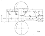
Figur 3- weitere Einzelheiten der erfindungsgemäßen Ausgestaltung.
- FIG. 1
- a schematic representation of an apparatus for rolling strip material in side view;
- FIG. 2
- Special features of an embodiment according to the invention;
- FIG. 3
- further details of the embodiment according to the invention.
In
Der Walzspalt, der insbesondere in
Die Tauchrollen sind mittels jeweils eines Stellantriebes 19 bzw. 20 in Richtung der Bewegungspfeile 11 bzw. 12 nach oben bzw. nach unten in der Zeichnungsebene gesehen verstellbar und werden bei konstanter Walzendrehzahl der den Walzspalt bestimmenden Walzen 4, 5 des Walzgerüstes 3 in Abhängigkeit von der Anstellung der Walzen 4, 5 positionsgesteuert, um die Geschwindigkeitsänderungen des Walzgutes, also des Bandmaterials 1, am Einlauf und am Auslauf des Walzgerüstes 3 auszugleichen. Die Abhaspel 7 und die Aufhaspel 8 sind zuggeregelt betrieben.The dipping rollers are seen by means of an
Die vor jeder Tauchrolle 9 und hinter jeder Tauchrolle 10 angeordneten Stützrollen 13, 14 bzw. 15, 16, über die das Bandmaterial 1 geführt ist, weisen jeweils eine Bandlängenerfassungseinrichtung und eine Bandgeschwindigkeitsüberwachungseinrichtung 21, 22 bzw. 23, 24 auf. Ferner ist die Abhaspel 7 und die Aufhaspel 8 jeweils mit einer Zugmesseinrichtung ZM versehen, mittels derer die Stromzufuhr, die bei 25, 26 angedeutet ist, zu den Antriebsmotoren MA der Haspeln 7, 8 regelbar ist, um den Haspelzug den Erfordernissen aus den Betriebsparametern angepasst zu halten.The upstream of each dipping
Des Weiteren ist eine Maschinensteuerung 27 vorgesehen, die die Stellwerte für die Anstellung der Walzen 4, 5 für einen vorbestimmbaren Walzspalt erfassen und verarbeiten bzw. speichern und mittels derer die Tauchrollen 9, 10 in Abhängigkeit davon positionssteuerbar sind. Dazu kommuniziert die Maschinensteuerung 27 mit dem Anstellsystem 6, mit den Bandlängenerfassungseinrichtungen und Bandgeschwindigkeitsüberwachungseinrichtungen 21, 22, 23, 24 mit den Stelleinrichtungen 19, 20 für die Tauchrollen 9, 10, so dass mittels der Maschinensteuerung 27 die Anstellung der Walzen 4, 5 für den vorbestimmten Walzspalt erfasst und die Tauchrollen 9, 10 in Abhängigkeit davon positionsgesteuert werden.Furthermore, a
Die den Walzspalt bestimmenden Walzen 4, 5 des Walzgerüstes 3 werden mit konstanter Walzendrehzahl betrieben. In der Zeichnung sind in
Der gesamte Bereich von der Abhaspel 7 bis zum Walzgerüst 3 wird als Einlaufbereich und der Bereich von dem Walzgerüst 3 bis zur Aufhaspel 8 als Auslaufbereich bezeichnet.The entire area from the
Die durch das Walzen von periodisch veränderlichen Banddicken bei konstanter Walzendrehzahl entstehenden Geschwindigkeitsänderungen des Walzgutes (Bandmaterials 1) im Einlauf und Auslauf des Walzgerüstes 3 werden durch die Bewegung der beiden Tauchrollen 9 und 10 ausgeglichen. Die Tauchrollen 9, 10 werden positionsgesteuert. Die Steuerung erfolgt direkt aus der Anstellung der Walzen 4, 5 in Verbindung mit Signalen zur gewalzten Bandlänge. Der Betrieb der beiden Haspeln 7 und 8 erfolgt zuggeregelt.The speed changes of the rolling stock (strip material 1) resulting from the rolling of periodically variable strip thicknesses at a constant roll speed in the inlet and outlet of the
Ziel ist es, die Bewegung der Tauchrollen 9, 10 direkt aus den Betriebsparametern des Walzvorganges abzuleiten. Auf diese Weise soll die Bewegungsrichtung und die Art der Bewegung (konstante Geschwindigkeit, Beschleunigung oder Verzögerung) der Tauchrollen 9, 10 durch das Profil des gewalzten Materials bestimmt werden.The aim is to derive the movement of the
Was die Ansteuerung der Tauchrollenbewegung betrifft, so wird diese direkt aus den Signalen für die Walzenanstellung sowie den Bandlängensignalen abgeleitet, die mittels der Erfassungseinrichtungen 21, 22, 23, 24 erfasst werden.As regards the control of the dipping roller movement, this is derived directly from the signals for the roller adjustment and the band length signals, which are detected by means of the
Die Bewegung der Tauchrollen 9, 10 erfolgt periodisch. Jede Periode der Tauchrollen 9, 10 im Ein- und Auslauf ist zeitlich exakt einer Walzperiode zugeordnet.The movement of the dipping
Zur weiteren Erläuterung wird nun auf die
Um die Bewegung T der Tauchrollen 9, 10 exakt zuordnen zu können, wird das Profil des gewalzten Materials einer Walzperiode L in Segmente unterteilt. Die einzelnen Segmente umfassen jeweils Bereiche mit konstanter Banddicke (a mit s1 und b mit s2) sowie mit veränderlicher Banddicke (Y und Z). Durch Ermittlung der Einzelquerschnitte kann immer einem Segment im Auslauf ein querschnittsgleiches und somit massegleiches Segment im Walzeneinlauf zugeordnet werden (aE und bE sowie yE und zE mit der Eingangsbanddicke s). Daraus ergibt sich für eine Walzperiode L die massegleiche Bandlänge im Einlauf LE.In order to be able to assign the movement T of the dipping
Aus den einzelnen Segmenten einer Walzperiode lässt sich eine durchschnittliche Banddicke sM im Auslauf errechnen. Diese durchschnittliche Banddicke ist ein Äquivalent für die durchschnittliche Geschwindigkeit im Walzenauslauf (VAM) und bestimmt somit auch die durchschnittliche Geschwindigkeit im Einlauf (VEM). Die Haspelgeschwindigkeiten in dem Ein- und Auslauf entsprechen dann jeweils diesen durchschnittlichen Geschwindigkeiten, so als ob unter konstanten Bedingungen das einlaufende Band der Dicke s auf die Dicke sM abgewalzt würde.From the individual segments of a rolling period, an average band thickness s M in the outlet can be calculated. This average strip thickness is equivalent to the average speed in the roll outlet (V AM ) and thus also determines the average speed in the inlet (V EM ). The reel speeds in the inlet and outlet then each correspond to these average speeds, as if under constant conditions the incoming strip of thickness s would be rolled down to the thickness s M.
Die segmentweise Betrachtung der Verhältnisse zwischen durchschnittlicher Banddicke und der Dicke in einem Segment lässt einen Rückschluss auf das jeweilige Geschwindigkeitsverhältnis zu. Je größer die Dickenunterschiede sind, desto größer ist auch der Geschwindigkeitsunterschied in diesem Segment des Walzenauslaufes.The segment-by-segment analysis of the ratios between the average strip thickness and the thickness in a segment allows a conclusion about the respective speed ratio. The greater the differences in thickness, the greater the speed difference in this segment of the roll outlet.
Für den Walzeneinlauf sind ebenfalls die Bewegungen der Walzenanstellung und somit das Walzprofil maßgebend für die aktuelle Geschwindigkeit. Bei konstanter Walzengeschwindigkeit und gleichbleibenden Zügen ist bei geringer Stichabnahme die Einlaufgeschwindigkeit höher als bei großer Stichabnahme. Den Segmenten im Auslauf lassen sich immer querschnittsgleiche Segmente im Walzeneinlauf zuordnen. Aus den Segmenten einer kompletten Periode lässt sich dann sowohl eine durchschnittliche Geschwindigkeit im Einlauf bestimmen, als auch nach Segmenten zugeordnet die Bewegung der Tauchrollen 9, 10 ermitteln.For the roller inlet, the movements of the roller adjustment and thus the rolling profile are also decisive for the current speed. At constant roll speed and consistent traction, the infeed speed is higher with a low pass decrease than with a large pass decrease. The segments in the outlet can always be cross-sectionally equal segments in the roll inlet assign. From the segments of a complete period, it is then possible to determine both an average speed in the inlet and to determine the movement of the dipping
Die Art und Richtung der Tauchrollenbewegungen 11, 12 (konstante Geschwindigkeit auf/ab, Verzögerung, Totpunkt oder Beschleunigung) ergeben sich somit aus den Walzparametern. Um die Bewegung der Tauchrollen 9, 10 exakt dem Walzprozess zuzuordnen, wird das auslaufende Walzprofil einer Periode L segmentweise verglichen mit einem volumengleichen Abschnitt gleicher Länge L mit der durchschnittlichen Dicke sM.The type and direction of the
Das Segment b ist mit der Dicke s2 dicker als die durchschnittliche Dicke sM. Dies bedeutet, dass die Geschwindigkeit des auslaufenden Bandes vA2 geringer ist als die durchschnittliche Geschwindigkeit vAM. Um dies auszugleichen ist eine konstante Aufwärtsbewegung der Tauchrolle erforderlich. Das Segment Z wird durch die Kreuzung der Dicke vom gewalzten Profil mit der mittleren Dicke in zwei Abschnitte geteilt (Z1 und Z2). Im Bereich Z1 wird die Dicke reduziert bis zur durchschnittlichen Dicke. Dies bedeutet, dass die Geschwindigkeit des auslaufenden Bandes beschleunigt wird, bis zur durchschnittlichen Geschwindigkeit vAM. Im Kreuzungspunkt sind durchschnittliche Geschwindigkeit und Geschwindigkeit des auslaufenden Bandes identisch. Für die Tauchrolle ergib sich daraus, dass die Aufwärtsbewegung der Tauchrolle gebremst wird und im Kreuzungspunkt die Rolle ihren oberen Totpunkt erreicht. Im Bereich Z2 wird die Dicke weiter reduziert bis zur Dicke s1. Die Geschwindigkeit des auslaufenden Bandes wird beschleunigt bis zur Geschwindigkeit vA1. Die Tauchrolle wird in diesem Bereich nach unten beschleunigt.The segment b is thicker than the average thickness s M with the thickness s 2 . This means that the speed of the outgoing band v A2 is less than the average speed v AM . To compensate for this, a constant upward movement of the dipping roller is required. The segment Z is divided into two sections (Z 1 and Z 2 ) by crossing the thickness of the medium-thickness rolled profile. In the area Z 1 , the thickness is reduced to the average thickness. This means that the speed of the outgoing band is accelerated, up to the average speed v AM . At the crossing point, the average speed and the speed of the outgoing band are identical. For the dipping roll this results in that the upward movement of the dipping roll is braked and in the crossing point the roll reaches its top dead center. In the area Z 2 , the thickness continues reduced to the thickness s 1 . The speed of the outgoing belt is accelerated up to the speed v A1 . The dipping roller is accelerated downwards in this area.
Das Segment a ist mit der Dicke s1 dünner als die durchschnittliche Dicke sM. Die Geschwindigkeit des auslaufenden Bandes vA1 ist somit größer als die durchschnittliche Geschwindigkeit vAM. Die Tauchrolle gleicht dies durch eine konstante Abwärtsbewegung aus.The segment a is thinner than the average thickness s M with the thickness s 1 . The speed of the outgoing band v A1 is thus greater than the average speed v AM . The dive roller compensates for this by a constant downward movement.
Für das Segment Y gilt, dass die Geschwindigkeit des auslaufenden Bandes reduziert wird bis zur Geschwindigkeit vA2. Im Bereich Y1 wird die Abwärtsbewegung gebremst bis zum unteren Totpunkt und im Bereich Y2 wird die Tauchrolle wieder nach oben beschleunigt. Die Steuerung der Tauchrollenbewegung im Einlauf folgt der Tauchrollensteuerung des Auslaufes.For the segment Y, the speed of the outgoing band is reduced to the speed v A2 . In the area Y 1 , the downward movement is slowed down to the bottom dead center and in the area Y 2 the dipping roller is accelerated upward again. The control of the dipping roller movement in the inlet follows the dipping roller control of the outlet.
Im Segment bE ist die Geschwindigkeit des einlaufenden Bandes vE2 höher als die durchschnittliche Geschwindigkeit und im Segment aE ist die Geschwindigkeit vE1 geringer.In the segment b E the speed of the incoming band v E2 is higher than the average speed and in the segment a E the speed v E1 is lower.
Die Tauchrollenbewegung gleicht dies aus und geht im Segment bE mit konstanter Geschwindigkeit nach oben und im Segment aE ebenso nach unten. Die Segmente ZE und YE sind ebenso durch Abbremsen, Totpunkt und Beschleunigen gekennzeichnet. Die Totpunkte werden jeweils zeitgleich mit den auslaufseitigen Totpunkten gesteuert.The dipping roller movement compensates for this and goes upwards in the segment b E at constant speed and also downwards in the segment a E. The segments Z E and Y E are also characterized by braking, dead center and acceleration. The dead points are each controlled simultaneously with the outlet-side dead centers.
Um die Bewegungen der Tauchrollen zu überwachen und gegebenenfalls zu korrigieren, sind jeweils die Rollen vor dem Einlauf und nach dem Auslauf einer Tauchrolle mit Impulsgebern zur Bandlängenerfassung und Geschwindigkeitsüberwachung versehen.In order to monitor and, if necessary, correct the movements of the dipping rollers, the rollers in each case before the inlet and after the exit of a dipping roller are provided with pulse detectors for the detection of the belt lengths and the speed.
Die Signale für die Tauchrollenbewegung können also exakt auf die Walzenanstellung und somit auf das Walzprofil abgestimmt werden.The signals for the dipping roller movement can therefore be matched exactly to the roller adjustment and thus to the rolled section.
Korrekturen können zum Beispiel notwendig werden, wenn bei sehr schnellen Bewegungen der Walzenanstellung der Einfluss der Walzendurchmesser so groß wird, dass die zusätzlich im Einlauf verdrängten oder freiwerdende Materialanteile die Tauchrollenbewegung beeinflussen oder wenn Dickenabweichungen des Bandes den Walzprozess beeinflussen.Corrections may be necessary, for example, if during very rapid movements of the roll adjustment, the influence of the roll diameter is so large that the additional in the inlet displaced or released material shares affect the Tauchrollenbewegung or if thickness deviations of the strip influence the rolling process.
Da die Bewegung der Tauchrollen sehr genau an die Walzenanstellung und somit an die jeweilige Profiländerung angepasst werden kann, ist eine konstante Wickelgeschwindigkeit und damit eine exakte Zugregelung für beide Haspeln problemlos möglich.Since the movement of the dipping rollers can be adapted very precisely to the roller adjustment and thus to the respective profile change, a constant winding speed and thus an exact tension control for both reels is possible without problems.
Es bleibt noch anzumerken, dass die im Ausführungsbeispiel dargestellten Vorgänge nur ein Beispiel sind. Es sind auch mehr als vier Segmente für eine Walzperiode möglich.It remains to be noted that the operations shown in the embodiment are only an example. There are also more than four segments possible for a rolling period.
Die Erfindung ist nicht auf die Ausführungsbeispiele beschränkt, sondern im Rahmen der Offenbarung vielfach variabel.The invention is not limited to the embodiments, but in the context of the disclosure often variable.
Alle in der Beschreibung und/oder Zeichnung offenbarten Einzel- und Kombinationsmerkmale werden als erfindungswesentlich angesehen.All disclosed in the description and / or drawing single and combination features are considered essential to the invention.
- 11
- Bandmaterialband material
- 22
- Bewegungsrichtung von 1Movement direction of 1
- 33
- Walzgerüstrolling mill
- 44
- Walzeroller
- 55
- Walzeroller
- 66
- Anstellsystemadjustment system
- 77
- Abhaspeluncoiler
- 88th
- Aufhaspelcoiler
- 99
- Tauchrollediving role
- 1010
- Tauchrollediving role
- 1111
- Bewegungsrichtung von 9Movement direction of 9
- 1212
- Bewegungsrichtung von 10Movement direction of 10
- 1313
- Umlenkrolleidler pulley
- 1414
- Umlenkrolleidler pulley
- 1515
- Umlenkrolleidler pulley
- 1616
- Umlenkrolleidler pulley
- 1717
- Führungsrolleleadership
- 1818
- Führungsrolleleadership
- 1919
- Stelleinrichtung von 9Setting device of 9
- 2020
- Stelleinrichtung von 10Actuator of 10
- 2121
- Bandlängenerfassungs- und Bandlängengeschwindigkeitsüberwachungs-einrichtungTape length detection and tape length speed monitoring device
- 2222
- Bandlängenerfassungs- und Bandlängengeschwindigkeitsüberwachungs-einrichtungTape length detection and tape length speed monitoring device
- 2323
- Bandlängenerfassungs- und Bandlängengeschwindigkeitsüberwachungs-einrichtungTape length detection and tape length speed monitoring device
- 2424
- Bandlängenerfassungs- und Bandlängengeschwindigkeitsüberwachungs-einrichtungTape length detection and tape length speed monitoring device
- 2525
- Stromversorgung von 7Power supply of 7
- 2626
- Stromversorgung von 8Power supply of 8
- ZMZM
- Zugmesseinrichtungtensile gauge
- MAMA
- Antriebsmotordrive motor
- 2727
- Maschinensteuerungmachine control
- TT
- Bewegung der TauchrollenMovement of dipping rollers
- LL
- Walzperioderolling period
Claims (10)
Applications Claiming Priority (1)
| Application Number | Priority Date | Filing Date | Title |
|---|---|---|---|
| DE102016103088 | 2016-02-23 |
Publications (2)
| Publication Number | Publication Date |
|---|---|
| EP3210681A1 true EP3210681A1 (en) | 2017-08-30 |
| EP3210681B1 EP3210681B1 (en) | 2020-01-15 |
Family
ID=58009739
Family Applications (1)
| Application Number | Title | Priority Date | Filing Date |
|---|---|---|---|
| EP17155391.0A Active EP3210681B1 (en) | 2016-02-23 | 2017-02-09 | Device and method for rolling a strip of material with variable thickness |
Country Status (3)
| Country | Link |
|---|---|
| US (1) | US10413949B2 (en) |
| EP (1) | EP3210681B1 (en) |
| ES (1) | ES2769264T3 (en) |
Cited By (3)
| Publication number | Priority date | Publication date | Assignee | Title |
|---|---|---|---|---|
| WO2020114976A1 (en) * | 2018-12-06 | 2020-06-11 | Sms Group Gmbh | Method for operating a roll stand for stepped rolling |
| CN112605124A (en) * | 2020-11-27 | 2021-04-06 | 广州普德机电设备有限公司 | Rolling equipment and forming method for continuous variable cross-section thin steel plate |
| WO2021175636A1 (en) * | 2020-03-06 | 2021-09-10 | Sms Group Gmbh | Roll stand |
Families Citing this family (4)
| Publication number | Priority date | Publication date | Assignee | Title |
|---|---|---|---|---|
| HUE063023T2 (en) * | 2016-12-30 | 2023-12-28 | Outokumpu Oy | Method and device for flexible rolling metal strips |
| CN107716550B (en) * | 2017-09-09 | 2019-03-29 | 首钢集团有限公司 | A kind of production method of low-alloy longitudinal thickness-variable steel plate |
| JP7135991B2 (en) * | 2019-04-25 | 2022-09-13 | トヨタ自動車株式会社 | Calibration judgment device and calibration judgment method |
| WO2021230307A1 (en) | 2020-05-14 | 2021-11-18 | 日本製鉄株式会社 | Method for producing reduced iron |
Citations (4)
| Publication number | Priority date | Publication date | Assignee | Title |
|---|---|---|---|---|
| JPH1034204A (en) * | 1996-07-29 | 1998-02-10 | Kawasaki Steel Corp | Tension controller for reversible rolling mill |
| EP1454681A2 (en) * | 2003-03-07 | 2004-09-08 | Sundwig GmbH | Device and method for rolling metal strips |
| EP1908534A1 (en) * | 2006-10-07 | 2008-04-09 | ACHENBACH BUSCHHÜTTEN GmbH | Rolling mill and method for flexible cold or hot one-way or reverse rolling of a metal strip |
| EP1121990B2 (en) | 2000-02-02 | 2012-02-29 | Josef Fröhling GmbH & Co. KG | Device for rolling strips with a periodically variable thickness |
-
2017
- 2017-02-09 EP EP17155391.0A patent/EP3210681B1/en active Active
- 2017-02-09 ES ES17155391T patent/ES2769264T3/en active Active
- 2017-02-21 US US15/438,396 patent/US10413949B2/en active Active
Patent Citations (4)
| Publication number | Priority date | Publication date | Assignee | Title |
|---|---|---|---|---|
| JPH1034204A (en) * | 1996-07-29 | 1998-02-10 | Kawasaki Steel Corp | Tension controller for reversible rolling mill |
| EP1121990B2 (en) | 2000-02-02 | 2012-02-29 | Josef Fröhling GmbH & Co. KG | Device for rolling strips with a periodically variable thickness |
| EP1454681A2 (en) * | 2003-03-07 | 2004-09-08 | Sundwig GmbH | Device and method for rolling metal strips |
| EP1908534A1 (en) * | 2006-10-07 | 2008-04-09 | ACHENBACH BUSCHHÜTTEN GmbH | Rolling mill and method for flexible cold or hot one-way or reverse rolling of a metal strip |
Cited By (4)
| Publication number | Priority date | Publication date | Assignee | Title |
|---|---|---|---|---|
| WO2020114976A1 (en) * | 2018-12-06 | 2020-06-11 | Sms Group Gmbh | Method for operating a roll stand for stepped rolling |
| WO2021175636A1 (en) * | 2020-03-06 | 2021-09-10 | Sms Group Gmbh | Roll stand |
| CN112605124A (en) * | 2020-11-27 | 2021-04-06 | 广州普德机电设备有限公司 | Rolling equipment and forming method for continuous variable cross-section thin steel plate |
| CN112605124B (en) * | 2020-11-27 | 2022-07-05 | 苏州吉润汽车零部件有限公司 | Rolling equipment and forming method for continuous variable cross-section thin steel plate |
Also Published As
| Publication number | Publication date |
|---|---|
| US10413949B2 (en) | 2019-09-17 |
| EP3210681B1 (en) | 2020-01-15 |
| US20170239700A1 (en) | 2017-08-24 |
| ES2769264T3 (en) | 2020-06-25 |
Similar Documents
| Publication | Publication Date | Title |
|---|---|---|
| EP3210681B1 (en) | Device and method for rolling a strip of material with variable thickness | |
| EP2477764B1 (en) | Method and device for continuously stretch-bend-leveling metal strips | |
| EP3584016B1 (en) | Wear reduction in coil box rollers | |
| EP1784266B1 (en) | Rolling mill for rolling a metallic strip | |
| EP2418031A1 (en) | Method for producing a metal strip using a casting rolling assembly and control and/or regulating device for a compound casting rolling assembly | |
| EP1908534B1 (en) | Rolling mill and method for flexible cold or hot one-way or reverse rolling of a metal strip | |
| AT410767B (en) | METHOD AND DEVICE FOR THE CONTINUOUS PRODUCTION OF A ROLLED METAL STRIP FROM A METAL MELT | |
| EP2741870B1 (en) | Rolling system and rolling method | |
| EP2621645B1 (en) | Method for actuating a tandem roll train, control and/or regulating device for a tandem roll train, machine-readable program code, storage medium and tandem roll train | |
| DE1427888B2 (en) | Device for reducing the thickness of strip material | |
| EP1121990B2 (en) | Device for rolling strips with a periodically variable thickness | |
| DE112007000641T5 (en) | Continuous cold rolling plants | |
| EP3720623B1 (en) | Stretching-bending-straightening system and method for the actuation thereof | |
| EP0734795B1 (en) | Method for feedforward thickness control in rolling of foils | |
| EP0752285A2 (en) | Method and apparatus for rolling strips with transversely irregularities in thickness and/or in length | |
| WO2011095265A2 (en) | Hot rolling train for rolling hot-rolled strip, method for operating a hot rolling train for rolling hot-rolled strip, and control device | |
| EP1669141B1 (en) | Process for the control of the cross-section of wires running out from a wire rolling mill and metal wire rolling mill | |
| EP2283941A1 (en) | Method for controlling and/or regulating a loop lifter surrounded by a mill train, control and/or regulating device for a mill train and mill train | |
| DE102018127672A1 (en) | Method for checking an edge section of a film web | |
| EP4103339B1 (en) | Determining a sensitivity of a target size of a rolling stock for an operating variable of a hot rolling mill | |
| EP3873685B1 (en) | Roll line | |
| DE102008037520B4 (en) | Apparatus and method for producing a metal foil | |
| EP2279805A1 (en) | Method for controlling and/or regulating a bearing on a metal band that passes through a mill train, control and/or regulating device and mill train | |
| DE1427812B2 (en) | Control device for guiding rolled strip in a rolling train | |
| DE102020117682A1 (en) | Straightening machine and method for straightening a metal strip or a flat metal part |
Legal Events
| Date | Code | Title | Description |
|---|---|---|---|
| PUAI | Public reference made under article 153(3) epc to a published international application that has entered the european phase |
Free format text: ORIGINAL CODE: 0009012 |
|
| STAA | Information on the status of an ep patent application or granted ep patent |
Free format text: STATUS: THE APPLICATION HAS BEEN PUBLISHED |
|
| AK | Designated contracting states |
Kind code of ref document: A1 Designated state(s): AL AT BE BG CH CY CZ DE DK EE ES FI FR GB GR HR HU IE IS IT LI LT LU LV MC MK MT NL NO PL PT RO RS SE SI SK SM TR |
|
| AX | Request for extension of the european patent |
Extension state: BA ME |
|
| STAA | Information on the status of an ep patent application or granted ep patent |
Free format text: STATUS: REQUEST FOR EXAMINATION WAS MADE |
|
| 17P | Request for examination filed |
Effective date: 20180117 |
|
| RBV | Designated contracting states (corrected) |
Designated state(s): AL AT BE BG CH CY CZ DE DK EE ES FI FR GB GR HR HU IE IS IT LI LT LU LV MC MK MT NL NO PL PT RO RS SE SI SK SM TR |
|
| STAA | Information on the status of an ep patent application or granted ep patent |
Free format text: STATUS: EXAMINATION IS IN PROGRESS |
|
| 17Q | First examination report despatched |
Effective date: 20181108 |
|
| GRAP | Despatch of communication of intention to grant a patent |
Free format text: ORIGINAL CODE: EPIDOSNIGR1 |
|
| STAA | Information on the status of an ep patent application or granted ep patent |
Free format text: STATUS: GRANT OF PATENT IS INTENDED |
|
| INTG | Intention to grant announced |
Effective date: 20190925 |
|
| GRAS | Grant fee paid |
Free format text: ORIGINAL CODE: EPIDOSNIGR3 |
|
| GRAA | (expected) grant |
Free format text: ORIGINAL CODE: 0009210 |
|
| STAA | Information on the status of an ep patent application or granted ep patent |
Free format text: STATUS: THE PATENT HAS BEEN GRANTED |
|
| REG | Reference to a national code |
Ref country code: DE Ref legal event code: R081 Ref document number: 502017003484 Country of ref document: DE Owner name: BILSTEIN GMBH & CO. KG, DE Free format text: FORMER OWNER: BILSTEIN GMBH & CO. KG, 58119 HAGEN, DE |
|
| AK | Designated contracting states |
Kind code of ref document: B1 Designated state(s): AL AT BE BG CH CY CZ DE DK EE ES FI FR GB GR HR HU IE IS IT LI LT LU LV MC MK MT NL NO PL PT RO RS SE SI SK SM TR |
|
| REG | Reference to a national code |
Ref country code: CH Ref legal event code: EP Ref country code: GB Ref legal event code: FG4D Free format text: NOT ENGLISH |
|
| REG | Reference to a national code |
Ref country code: IE Ref legal event code: FG4D Free format text: LANGUAGE OF EP DOCUMENT: GERMAN |
|
| REG | Reference to a national code |
Ref country code: AT Ref legal event code: REF Ref document number: 1224700 Country of ref document: AT Kind code of ref document: T Effective date: 20200215 |
|
| REG | Reference to a national code |
Ref country code: DE Ref legal event code: R096 Ref document number: 502017003484 Country of ref document: DE |
|
| REG | Reference to a national code |
Ref country code: NL Ref legal event code: FP |
|
| REG | Reference to a national code |
Ref country code: SE Ref legal event code: TRGR |
|
| REG | Reference to a national code |
Ref country code: ES Ref legal event code: FG2A Ref document number: 2769264 Country of ref document: ES Kind code of ref document: T3 Effective date: 20200625 |
|
| REG | Reference to a national code |
Ref country code: LT Ref legal event code: MG4D |
|
| PG25 | Lapsed in a contracting state [announced via postgrant information from national office to epo] |
Ref country code: PT Free format text: LAPSE BECAUSE OF FAILURE TO SUBMIT A TRANSLATION OF THE DESCRIPTION OR TO PAY THE FEE WITHIN THE PRESCRIBED TIME-LIMIT Effective date: 20200607 Ref country code: NO Free format text: LAPSE BECAUSE OF FAILURE TO SUBMIT A TRANSLATION OF THE DESCRIPTION OR TO PAY THE FEE WITHIN THE PRESCRIBED TIME-LIMIT Effective date: 20200415 Ref country code: FI Free format text: LAPSE BECAUSE OF FAILURE TO SUBMIT A TRANSLATION OF THE DESCRIPTION OR TO PAY THE FEE WITHIN THE PRESCRIBED TIME-LIMIT Effective date: 20200115 Ref country code: RS Free format text: LAPSE BECAUSE OF FAILURE TO SUBMIT A TRANSLATION OF THE DESCRIPTION OR TO PAY THE FEE WITHIN THE PRESCRIBED TIME-LIMIT Effective date: 20200115 |
|
| PG25 | Lapsed in a contracting state [announced via postgrant information from national office to epo] |
Ref country code: LV Free format text: LAPSE BECAUSE OF FAILURE TO SUBMIT A TRANSLATION OF THE DESCRIPTION OR TO PAY THE FEE WITHIN THE PRESCRIBED TIME-LIMIT Effective date: 20200115 Ref country code: IS Free format text: LAPSE BECAUSE OF FAILURE TO SUBMIT A TRANSLATION OF THE DESCRIPTION OR TO PAY THE FEE WITHIN THE PRESCRIBED TIME-LIMIT Effective date: 20200515 Ref country code: GR Free format text: LAPSE BECAUSE OF FAILURE TO SUBMIT A TRANSLATION OF THE DESCRIPTION OR TO PAY THE FEE WITHIN THE PRESCRIBED TIME-LIMIT Effective date: 20200416 Ref country code: HR Free format text: LAPSE BECAUSE OF FAILURE TO SUBMIT A TRANSLATION OF THE DESCRIPTION OR TO PAY THE FEE WITHIN THE PRESCRIBED TIME-LIMIT Effective date: 20200115 Ref country code: BG Free format text: LAPSE BECAUSE OF FAILURE TO SUBMIT A TRANSLATION OF THE DESCRIPTION OR TO PAY THE FEE WITHIN THE PRESCRIBED TIME-LIMIT Effective date: 20200415 |
|
| REG | Reference to a national code |
Ref country code: CH Ref legal event code: PL |
|
| REG | Reference to a national code |
Ref country code: DE Ref legal event code: R097 Ref document number: 502017003484 Country of ref document: DE |
|
| REG | Reference to a national code |
Ref country code: BE Ref legal event code: MM Effective date: 20200229 |
|
| PG25 | Lapsed in a contracting state [announced via postgrant information from national office to epo] |
Ref country code: LT Free format text: LAPSE BECAUSE OF FAILURE TO SUBMIT A TRANSLATION OF THE DESCRIPTION OR TO PAY THE FEE WITHIN THE PRESCRIBED TIME-LIMIT Effective date: 20200115 Ref country code: EE Free format text: LAPSE BECAUSE OF FAILURE TO SUBMIT A TRANSLATION OF THE DESCRIPTION OR TO PAY THE FEE WITHIN THE PRESCRIBED TIME-LIMIT Effective date: 20200115 Ref country code: SM Free format text: LAPSE BECAUSE OF FAILURE TO SUBMIT A TRANSLATION OF THE DESCRIPTION OR TO PAY THE FEE WITHIN THE PRESCRIBED TIME-LIMIT Effective date: 20200115 Ref country code: LU Free format text: LAPSE BECAUSE OF NON-PAYMENT OF DUE FEES Effective date: 20200209 Ref country code: RO Free format text: LAPSE BECAUSE OF FAILURE TO SUBMIT A TRANSLATION OF THE DESCRIPTION OR TO PAY THE FEE WITHIN THE PRESCRIBED TIME-LIMIT Effective date: 20200115 Ref country code: MC Free format text: LAPSE BECAUSE OF FAILURE TO SUBMIT A TRANSLATION OF THE DESCRIPTION OR TO PAY THE FEE WITHIN THE PRESCRIBED TIME-LIMIT Effective date: 20200115 Ref country code: SK Free format text: LAPSE BECAUSE OF FAILURE TO SUBMIT A TRANSLATION OF THE DESCRIPTION OR TO PAY THE FEE WITHIN THE PRESCRIBED TIME-LIMIT Effective date: 20200115 Ref country code: DK Free format text: LAPSE BECAUSE OF FAILURE TO SUBMIT A TRANSLATION OF THE DESCRIPTION OR TO PAY THE FEE WITHIN THE PRESCRIBED TIME-LIMIT Effective date: 20200115 |
|
| PLBE | No opposition filed within time limit |
Free format text: ORIGINAL CODE: 0009261 |
|
| STAA | Information on the status of an ep patent application or granted ep patent |
Free format text: STATUS: NO OPPOSITION FILED WITHIN TIME LIMIT |
|
| PG25 | Lapsed in a contracting state [announced via postgrant information from national office to epo] |
Ref country code: CH Free format text: LAPSE BECAUSE OF NON-PAYMENT OF DUE FEES Effective date: 20200229 Ref country code: LI Free format text: LAPSE BECAUSE OF NON-PAYMENT OF DUE FEES Effective date: 20200229 |
|
| 26N | No opposition filed |
Effective date: 20201016 |
|
| REG | Reference to a national code |
Ref country code: DE Ref legal event code: R082 Ref document number: 502017003484 Country of ref document: DE Representative=s name: PATENTANWAELTE KOECHLING, DOERING PARTG MBB, DE Ref country code: DE Ref legal event code: R081 Ref document number: 502017003484 Country of ref document: DE Owner name: BILSTEIN GMBH & CO. KG, DE Free format text: FORMER OWNERS: BILSTEIN GMBH & CO. KG, 58119 HAGEN, DE; TILGERT WALZMASCHINENBAU GMBH, 58642 ISERLOHN, DE |
|
| REG | Reference to a national code |
Ref country code: NL Ref legal event code: PD Owner name: BILSTEIN GMBH & CO. KG; DE Free format text: DETAILS ASSIGNMENT: CHANGE OF OWNER(S), ASSIGNMENT; FORMER OWNER NAME: TILGERT WALZWERKSMASCHINENBAU GMBH Effective date: 20210108 |
|
| PG25 | Lapsed in a contracting state [announced via postgrant information from national office to epo] |
Ref country code: IE Free format text: LAPSE BECAUSE OF NON-PAYMENT OF DUE FEES Effective date: 20200209 |
|
| REG | Reference to a national code |
Ref country code: ES Ref legal event code: PC2A Owner name: BILSTEIN GMBH & CO. KG Effective date: 20210216 |
|
| PG25 | Lapsed in a contracting state [announced via postgrant information from national office to epo] |
Ref country code: SI Free format text: LAPSE BECAUSE OF FAILURE TO SUBMIT A TRANSLATION OF THE DESCRIPTION OR TO PAY THE FEE WITHIN THE PRESCRIBED TIME-LIMIT Effective date: 20200115 Ref country code: BE Free format text: LAPSE BECAUSE OF NON-PAYMENT OF DUE FEES Effective date: 20200229 Ref country code: PL Free format text: LAPSE BECAUSE OF FAILURE TO SUBMIT A TRANSLATION OF THE DESCRIPTION OR TO PAY THE FEE WITHIN THE PRESCRIBED TIME-LIMIT Effective date: 20200115 |
|
| REG | Reference to a national code |
Ref country code: GB Ref legal event code: 732E Free format text: REGISTERED BETWEEN 20210211 AND 20210217 |
|
| PG25 | Lapsed in a contracting state [announced via postgrant information from national office to epo] |
Ref country code: MT Free format text: LAPSE BECAUSE OF FAILURE TO SUBMIT A TRANSLATION OF THE DESCRIPTION OR TO PAY THE FEE WITHIN THE PRESCRIBED TIME-LIMIT Effective date: 20200115 Ref country code: CY Free format text: LAPSE BECAUSE OF FAILURE TO SUBMIT A TRANSLATION OF THE DESCRIPTION OR TO PAY THE FEE WITHIN THE PRESCRIBED TIME-LIMIT Effective date: 20200115 |
|
| PG25 | Lapsed in a contracting state [announced via postgrant information from national office to epo] |
Ref country code: MK Free format text: LAPSE BECAUSE OF FAILURE TO SUBMIT A TRANSLATION OF THE DESCRIPTION OR TO PAY THE FEE WITHIN THE PRESCRIBED TIME-LIMIT Effective date: 20200115 Ref country code: AL Free format text: LAPSE BECAUSE OF FAILURE TO SUBMIT A TRANSLATION OF THE DESCRIPTION OR TO PAY THE FEE WITHIN THE PRESCRIBED TIME-LIMIT Effective date: 20200115 |
|
| PGFP | Annual fee paid to national office [announced via postgrant information from national office to epo] |
Ref country code: NL Payment date: 20230221 Year of fee payment: 7 |
|
| REG | Reference to a national code |
Ref country code: AT Ref legal event code: MM01 Ref document number: 1224700 Country of ref document: AT Kind code of ref document: T Effective date: 20220209 |
|
| PG25 | Lapsed in a contracting state [announced via postgrant information from national office to epo] |
Ref country code: AT Free format text: LAPSE BECAUSE OF NON-PAYMENT OF DUE FEES Effective date: 20220209 |
|
| PGFP | Annual fee paid to national office [announced via postgrant information from national office to epo] |
Ref country code: FR Payment date: 20230216 Year of fee payment: 7 Ref country code: ES Payment date: 20230317 Year of fee payment: 7 Ref country code: CZ Payment date: 20230130 Year of fee payment: 7 |
|
| PGFP | Annual fee paid to national office [announced via postgrant information from national office to epo] |
Ref country code: TR Payment date: 20230208 Year of fee payment: 7 Ref country code: SE Payment date: 20230216 Year of fee payment: 7 Ref country code: IT Payment date: 20230217 Year of fee payment: 7 Ref country code: GB Payment date: 20230217 Year of fee payment: 7 |
|
| P01 | Opt-out of the competence of the unified patent court (upc) registered |
Effective date: 20230509 |
|
| PGFP | Annual fee paid to national office [announced via postgrant information from national office to epo] |
Ref country code: DE Payment date: 20230502 Year of fee payment: 7 |