EP3209975B1 - Ensemble capteur de position - Google Patents
Ensemble capteur de position Download PDFInfo
- Publication number
- EP3209975B1 EP3209975B1 EP15790766.8A EP15790766A EP3209975B1 EP 3209975 B1 EP3209975 B1 EP 3209975B1 EP 15790766 A EP15790766 A EP 15790766A EP 3209975 B1 EP3209975 B1 EP 3209975B1
- Authority
- EP
- European Patent Office
- Prior art keywords
- housing
- moving element
- stator
- temperature
- signal
- Prior art date
- Legal status (The legal status is an assumption and is not a legal conclusion. Google has not performed a legal analysis and makes no representation as to the accuracy of the status listed.)
- Active
Links
- 238000004804 winding Methods 0.000 claims description 58
- 238000000034 method Methods 0.000 claims description 24
- 230000006870 function Effects 0.000 claims description 21
- 230000003750 conditioning effect Effects 0.000 claims description 20
- 230000005284 excitation Effects 0.000 claims description 16
- 238000009529 body temperature measurement Methods 0.000 claims description 4
- 239000000872 buffer Substances 0.000 claims description 3
- 238000012937 correction Methods 0.000 description 12
- 238000006243 chemical reaction Methods 0.000 description 6
- 238000010586 diagram Methods 0.000 description 5
- 239000004020 conductor Substances 0.000 description 4
- 230000008878 coupling Effects 0.000 description 4
- 238000010168 coupling process Methods 0.000 description 4
- 238000005859 coupling reaction Methods 0.000 description 4
- 238000006073 displacement reaction Methods 0.000 description 4
- 238000005070 sampling Methods 0.000 description 4
- 230000010354 integration Effects 0.000 description 3
- 125000006850 spacer group Chemical group 0.000 description 3
- 238000004519 manufacturing process Methods 0.000 description 2
- 230000004048 modification Effects 0.000 description 2
- 238000012986 modification Methods 0.000 description 2
- 230000008569 process Effects 0.000 description 2
- 230000001360 synchronised effect Effects 0.000 description 2
- XEEYBQQBJWHFJM-UHFFFAOYSA-N Iron Chemical group [Fe] XEEYBQQBJWHFJM-UHFFFAOYSA-N 0.000 description 1
- 230000003321 amplification Effects 0.000 description 1
- 230000001419 dependent effect Effects 0.000 description 1
- 238000001514 detection method Methods 0.000 description 1
- 239000000835 fiber Substances 0.000 description 1
- 238000001914 filtration Methods 0.000 description 1
- 230000004907 flux Effects 0.000 description 1
- 230000036039 immunity Effects 0.000 description 1
- 230000001939 inductive effect Effects 0.000 description 1
- 239000000463 material Substances 0.000 description 1
- 238000003199 nucleic acid amplification method Methods 0.000 description 1
- 238000012545 processing Methods 0.000 description 1
- 239000000523 sample Substances 0.000 description 1
- 230000009466 transformation Effects 0.000 description 1
Images


Classifications
-
- G—PHYSICS
- G01—MEASURING; TESTING
- G01D—MEASURING NOT SPECIALLY ADAPTED FOR A SPECIFIC VARIABLE; ARRANGEMENTS FOR MEASURING TWO OR MORE VARIABLES NOT COVERED IN A SINGLE OTHER SUBCLASS; TARIFF METERING APPARATUS; MEASURING OR TESTING NOT OTHERWISE PROVIDED FOR
- G01D5/00—Mechanical means for transferring the output of a sensing member; Means for converting the output of a sensing member to another variable where the form or nature of the sensing member does not constrain the means for converting; Transducers not specially adapted for a specific variable
- G01D5/12—Mechanical means for transferring the output of a sensing member; Means for converting the output of a sensing member to another variable where the form or nature of the sensing member does not constrain the means for converting; Transducers not specially adapted for a specific variable using electric or magnetic means
- G01D5/14—Mechanical means for transferring the output of a sensing member; Means for converting the output of a sensing member to another variable where the form or nature of the sensing member does not constrain the means for converting; Transducers not specially adapted for a specific variable using electric or magnetic means influencing the magnitude of a current or voltage
- G01D5/20—Mechanical means for transferring the output of a sensing member; Means for converting the output of a sensing member to another variable where the form or nature of the sensing member does not constrain the means for converting; Transducers not specially adapted for a specific variable using electric or magnetic means influencing the magnitude of a current or voltage by varying inductance, e.g. by a movable armature
- G01D5/22—Mechanical means for transferring the output of a sensing member; Means for converting the output of a sensing member to another variable where the form or nature of the sensing member does not constrain the means for converting; Transducers not specially adapted for a specific variable using electric or magnetic means influencing the magnitude of a current or voltage by varying inductance, e.g. by a movable armature differentially influencing two coils
- G01D5/2291—Linear or rotary variable differential transformers (LVDTs/RVDTs) having a single primary coil and two secondary coils
-
- G—PHYSICS
- G01—MEASURING; TESTING
- G01D—MEASURING NOT SPECIALLY ADAPTED FOR A SPECIFIC VARIABLE; ARRANGEMENTS FOR MEASURING TWO OR MORE VARIABLES NOT COVERED IN A SINGLE OTHER SUBCLASS; TARIFF METERING APPARATUS; MEASURING OR TESTING NOT OTHERWISE PROVIDED FOR
- G01D5/00—Mechanical means for transferring the output of a sensing member; Means for converting the output of a sensing member to another variable where the form or nature of the sensing member does not constrain the means for converting; Transducers not specially adapted for a specific variable
- G01D5/12—Mechanical means for transferring the output of a sensing member; Means for converting the output of a sensing member to another variable where the form or nature of the sensing member does not constrain the means for converting; Transducers not specially adapted for a specific variable using electric or magnetic means
- G01D5/14—Mechanical means for transferring the output of a sensing member; Means for converting the output of a sensing member to another variable where the form or nature of the sensing member does not constrain the means for converting; Transducers not specially adapted for a specific variable using electric or magnetic means influencing the magnitude of a current or voltage
- G01D5/20—Mechanical means for transferring the output of a sensing member; Means for converting the output of a sensing member to another variable where the form or nature of the sensing member does not constrain the means for converting; Transducers not specially adapted for a specific variable using electric or magnetic means influencing the magnitude of a current or voltage by varying inductance, e.g. by a movable armature
- G01D5/204—Mechanical means for transferring the output of a sensing member; Means for converting the output of a sensing member to another variable where the form or nature of the sensing member does not constrain the means for converting; Transducers not specially adapted for a specific variable using electric or magnetic means influencing the magnitude of a current or voltage by varying inductance, e.g. by a movable armature by influencing the mutual induction between two or more coils
-
- G—PHYSICS
- G01—MEASURING; TESTING
- G01D—MEASURING NOT SPECIALLY ADAPTED FOR A SPECIFIC VARIABLE; ARRANGEMENTS FOR MEASURING TWO OR MORE VARIABLES NOT COVERED IN A SINGLE OTHER SUBCLASS; TARIFF METERING APPARATUS; MEASURING OR TESTING NOT OTHERWISE PROVIDED FOR
- G01D5/00—Mechanical means for transferring the output of a sensing member; Means for converting the output of a sensing member to another variable where the form or nature of the sensing member does not constrain the means for converting; Transducers not specially adapted for a specific variable
- G01D5/12—Mechanical means for transferring the output of a sensing member; Means for converting the output of a sensing member to another variable where the form or nature of the sensing member does not constrain the means for converting; Transducers not specially adapted for a specific variable using electric or magnetic means
- G01D5/14—Mechanical means for transferring the output of a sensing member; Means for converting the output of a sensing member to another variable where the form or nature of the sensing member does not constrain the means for converting; Transducers not specially adapted for a specific variable using electric or magnetic means influencing the magnitude of a current or voltage
- G01D5/20—Mechanical means for transferring the output of a sensing member; Means for converting the output of a sensing member to another variable where the form or nature of the sensing member does not constrain the means for converting; Transducers not specially adapted for a specific variable using electric or magnetic means influencing the magnitude of a current or voltage by varying inductance, e.g. by a movable armature
- G01D5/22—Mechanical means for transferring the output of a sensing member; Means for converting the output of a sensing member to another variable where the form or nature of the sensing member does not constrain the means for converting; Transducers not specially adapted for a specific variable using electric or magnetic means influencing the magnitude of a current or voltage by varying inductance, e.g. by a movable armature differentially influencing two coils
-
- H—ELECTRICITY
- H02—GENERATION; CONVERSION OR DISTRIBUTION OF ELECTRIC POWER
- H02K—DYNAMO-ELECTRIC MACHINES
- H02K24/00—Machines adapted for the instantaneous transmission or reception of the angular displacement of rotating parts, e.g. synchro, selsyn
Definitions
- the present invention relates generally to the field of position sensors, and more particularly to a fully integrated position sensor assembly.
- Position sensors are used in many applications, including aircraft, military, transportation, energy, automation and industrial. Such sensors may include encoders, hall position sensors, potentiometers, resolvers and rotary variable differential transformers (RVDTs). RVDTs and resolvers are used in critical applications where more reliable solutions are required. For example, in the aircraft market, the use of fly-by-wire and fly-by-light architectures means that more position sensors are required on each airframe. RVDTs are well known in the market. An electromechanical transducer is used to provide a variable alternating current output voltage that is generally linearly proportional to the angular displacement of an input shaft.
- US5811967A relates to a valve position sensor apparatus for measuring the linear position of an EGR valve, the apparatus comprising a probe includinding parallel, spaced apart, coextensive primary and secondary windings having a transformer coupling.
- the tubular member is movable with the EGR valve stem and is comprised of a material adapted to alter the transformer coupling of the overlaid windings.
- An AC signal is supplied to the primary winding thereby inducing a signal in the secondary winding, the magnitude of the induced signal being dependent on the transformer coupling.
- An output means monitors the signal induced in the secondary winding and provides an output signal related to the linear position of the EGR valve.
- EP2530284A2 relates to a motor-driven throttle valve control device in which an excitation conductor is attached to the tip of a throttle shaft to which the throttle valve is attached.
- a gear cover is provided with a magnetic field exciting conductor and a signal detection conductor facing the excitation conductor.
- a position sensor assembly comprising a housing (16) having a least one inner cavity (20, 21), a stator (22) disposed within the housing, a moving element (23) disposed within the housing and configured and arranged to move relative to the stator, the stator comprising primary windings (24) and secondary windings (25, 26), the secondary windings configured and arranged to provide an output signal (27) as a function of movement of the moving element relative to the stator, signal conditioning electronics (28) disposed in the housing and communicating with the primary windings and the secondary windings, the signal conditioning electronics comprising an integrated circuit (29) configured and arranged to provide excitation of the primary windings and to demodulate the output signal of the secondary wind
- the housing may comprise a sensor housing subassembly (18) having a first inner cavity (20) and an electronics housing subassembly (19) having a second inner cavity (21), and the stator and the moving element may be disposed within the first inner cavity of the sensor housing subassembly, and the signal conditioning electronics may be disposed within the second inner cavity of the electronics housing subassembly.
- the electronics housing subassembly may be removably connected to the sensor housing subassembly.
- the sensor housing subassembly may comprise a bearing end portion (36), a sensor body portion (38) and an intermediate portion (39), and the electronics housing subassembly may comprise an electronics body portion (40) and a second end portion (41).
- the sensor housing subassembly may comprise a signal output port.
- the moving element may be configured and arranged to move linearly along a central axis relative to the stator or to rotate about a central axis relative to the stator.
- the moving element may comprise a magnet.
- the stator and moving element may be selected from a group consisting of a rotary variable differential transformer and a resolver.
- the signal conditioning electronics may comprise a converter configured and arranged to convert the output signal to a digital signal.
- the signal conditioning electronics may comprise a signal filter configured and arranged to filter out a carrier frequency.
- the signal conditioning electronics may comprise a DC signal buffer.
- the assembly may comprise a temperature sensor (55) configured and arranged to provide a temperature signal (101) to the integrated circuit and the integrated circuit is configured and arranged to provide mover position output (104) compensated (84) as a function of the temperature signal.
- the assembly may comprise a mover positional calibration data (127) and the integrated circuit is configured and arranged to provide a mover position output (94) compensated (83) as a function of the calibration data.
- the assembly may comprise a temperature sensor (55) configured and arranged to provide a temperature signal (101) to the integrated circuit and a mover positional calibration data (117, 127), and the integrated circuit is configured and arranged to provide a mover position output (85) compensated as a function of the calibration data and the temperature signal.
- a method of calibrating a position sensor assembly comprising the steps of providing a position sensor assembly having a housing with at least one inner cavity, a stator disposed within the housing, a moving element disposed within the housing and configured and arranged to move relative to the stator, an input element extending through the housing and connected to the moving element, the stator comprising primary windings and secondary windings, the secondary windings configured and arranged to provide an output signal as a function of movement of the moving element relative to the stator.
- the calibration method further comprises providing signal conditioning electronics in the housing having a memory and an integrated circuit communicating with the primary windings and the secondary windings and configured and arranged to provide excitation of the primary windings and to condition the output signal of the secondary windings, providing a temperature sensor in said housing, mounting the position sensor assembly on an external actuator (111, 121), wherein the external actuator is configured and arranged to drive the moving element of the position sensor assembly through a range of reference positions, operating the external actuator through the range of reference positions, calculating a position error (115) as a function of the output signal of the secondary windings (113) and the reference position (112), sensing a measured temperature (124) with the temperature sensor of the position sensor assembly, calculating a temperature error (125) as a function of the output signal of the secondary windings (123), the measured temperature (124), and a temperature reference (122), and storing the position error (116) and the temperature error (126) in the memory (59).
- the method further comprises the step of providing a mover position output (85) compensate
- a method of compensating a position sensor assembly comprising the steps of providing a position sensor assembly having a housing with at least one inner cavity, a stator disposed within said housing, a moving element disposed within the housing and configured and arranged to move relative to the stator, an input element extending through the housing and connected to the moving element, the stator comprising primary windings and secondary windings, the secondary windings configured and arranged to provide an output signal as a function of movement of the moving element relative to the stator; providing signal conditioning electronics in the housing having a memory and an integrated circuit communicating with the primary windings and said secondary windings and configured and arranged to provide excitation of the primary windings and to condition the output signal of the secondary windings, providing a positional calibration dataset (117), providing a temperature calibration dataset (127), providing a temperature sensor in the housing; connecting the moving element to an external actuator; operating the external actuator; taking temperature measurements with the temperature sensor, and providing a mover position output (85) compensated as a function of the
- the terms “horizontal”, “vertical”, “left”, “right”, “up” and “down”, as well as adjectival and adverbial derivatives thereof simply refer to the orientation of the illustrated structure as the particular drawing figure faces the reader.
- the terms “inwardly” and “outwardly” generally refer to the orientation of a surface relative to its axis of elongation, or axis of rotation, as appropriate.
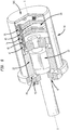
- assembly 15 generally includes RVDT 17, integrated conversion and signal conditioning electronics 28 and housing 16.
- RVDT 17 is an electromechanical transducer that provides a variable alternating current output voltage that is linearly proportional to the angular displacement of input shaft 35. When energized by electronics 28 with a fixed AC source 32, output signal 27 is linear within a specific range over the angular displacement.
- RVDT 17 generally comprises iron core rotor 23 rotationally supported within cavity 20 of subassembly housing 18.
- Stator 22 includes primary longitudinally extending linked excitation coils 24 and a pair of secondary longitudinally extending linked output coils 25 and 26.
- a fixed alternating current excitation 32 is applied to primary stator coils 24, which are electromagnetically coupled to secondary coils 25 and 26. This coupling is proportional to the angular displacement of rotor 23 and input shaft 35 about axis x-x.
- Output pairs 25 and 26 are structured so that one coil set 25 is in phase with excitation coils 24, and the second set 26 is 180 degrees out of phase with excitation coils 24.
- the output voltage is cancelled and results in a zero value signal. This is referred to as the electrical zero position or E.Z.
- E.Z electrical zero position
- the resulting output signal 27 has a magnitude in phase relationship proportional to the direction of rotation.
- RVDT 17 performs essentially like a transformer, excitation voltage changes will cause direction proportional changes to the output (transformation ratio).
- a MOOG-MCG-MURPHY AS-827 RVDT may be used.
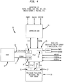
- integrated electronics 28 generally includes circuit board 30 and mezzanine or expansion board 31.
- Circuit board 30 includes microcontroller integrated circuit 29, having configurable blocks 33 and 34 that excite 32 primary windings 24 and filter signal 27 from secondary windings 25 and 26, and interface 44.
- Integrated circuit 29 controls the frequency and amplitude of excitation signal 32, demodulates signal 27 from the secondary windings, filters to eliminate the carrier frequency, samples and converts 82 the received analog signal 27 into digital format, and calibrates 110, 120, compensates 83, 84, amplifies, scales and buffers the signal for output 85.
- Mezzanine board 31 is provided to allow for custom interfaces, such as a digital interface for a standard digital bus.
- circuit board 30 includes additional chip set 58, which in this embodiment includes temperature sensor 55, voltage reference chip 56 and oscillator 57, with outputs to integrated circuit 29.
- housing 16 generally comprises sensor housing subassembly 18 having cavity 20, and electronics housing subassembly 19 having cavity 21.
- Sensor housing subassembly 18 is formed by annular bearing end portion 36, hollow cylindrical body portion 38 and circular intermediate end plate 39.
- the left end of cylindrical portion 38 includes inwardly extending double seat 48, defined by rightwardly-facing annular surface 49, inwardly-facing cylindrical surface 50, and rightwardly-facing annular surface 51.
- the left ends of coils 24, 25 and 26 abut against and are axially restrained by surface 49 and the left annular face of bearing 42 abuts against and is axially restrained by surface 51.
- Annular bearings 42 and 43 positioned axially along axis x-x on the left and right outer sides, respectively, of cavity 20, support rotor 23 within cavity 20 of housing subassembly 18 so as to allow rotor 23 to rotate about axis x-x relative to housing 16.
- Coil assembly 22 is positioned axially interior to bearings 42 and 43, respectively, within cavity 20.
- Coil 24 is positioned circumferentially between coils 25 and 26.
- Electronic housing subassembly 19 generally comprises hollow cylindrical body 40 having circular end plate 41 and forming inner cylindrical cavity 21.
- Integrated electronics 28 are stacked axially along axis x-x within cavity 21 of subassembly housing 19.
- circuit board 30 is positioned axially to the right of intermediate housing plate 39 and mezzanine board 31 is positioned axially to the right of board 30.
- each of coils 24-26, bearing 43, intermediate housing plate 39, board 30 and mezzanine board 31 has an outer diameter slightly less than the inner diameter of cylindrical housing portions 38 and 40 so as to allow for the axial stacking transversely along axis x-x described above.
- housing 16 contains both RVDT 17 and electronics 28 in a fully integrated package.
- Microcontroller integrated circuit 29 is configured to provide initial calibration for inherent non-linearity in the stator 22, rotor 23 and their mechanical assembly, as well as for thermal non-linearity, of each assembly 15 and to provide operational compensation 80 for such linearity and temperature variations.
- compensation routine 80 is directed to producing a linear output signal 85 and is described with reference to FIGS. 8-14 .
- signal 27 is received 81 as an output from RVDT 17 in the form of an AC signal (sine wave) of varying amplitude and phase with respect to excitation signal 32.
- Output signal 27 is then converted from analog to digital at step 82.
- the voltage reference from voltage chip 56 is used to provide an accurate and stable voltage reference in the conversion and the signal from oscillator 57 is applied to provide more accurate timing during sampling.
- Sampling can be synchronous with demodulation occurring in the analog domain, or sampling can be asynchronous with demodulation occurring in the digital or software domain.
- the ability of integrated circuit 29 to handle both synchronous and asynchronous sampling provides flexibility regarding execution of the signal acquisition and processing techniques described herein, and further allows for the implementation of all described position sensor assembly 15 embodiments.
- the signal is compensated for linearity at step 83 and temperature at step 84.
- a method of linear compensation 83 is further shown and described with reference to FIG. 9 .
- the system acquires a measured position 91 from the raw position value output from the demodulation and analog to digital conversion at step 82. From here, the system may perform either of error correction or error lookup at step 92.
- Error correction, or polynomial correction maps the error as a function of a measured position of rotor 23. Constants are generated, which provide a polynomial fit to the measured error. The generated polynomial can be used to compensate for any error that is present in the measured position.
- Polynomial correction requires less memory than error lookup, but may not be able to compensate all situations. Conversely, utilizing error lookup at step 92 may require more memory than error correction, but error lookup can compensate all situations.
- linear compensation method 83 After performing either error correction or error lookup at step 92, linear compensation method 83 then performs error subtraction at step 93, wherein a linearized (compensated) position 94 is calculated as being equal to the measured position 91 minus the error (taken from step 92).
- the linear compensation steps of FIG. 9 may be performed at a production factory, resulting in a position sensor assembly that will be able to be continuously corrected for linear compensation during operation using the factory corrected values.
- the linearized (compensated) position 94 is a position that has been fully compensated for linear errors in the assembly 15. However, errors due to temperature may still be present.
- position sensor method 80 of FIG. 8 proceeds to temperature compensation method 84, which is herein described in detail with reference to FIG. 10 .
- linearized position 94 is calculated with respect to the procedure illustrated in FIG. 9 and disclosed hereinabove.
- temperature of the position sensor assembly is measured.
- the temperature is measured by discrete temperature sensor 55 on main processor board 30 of position sensor assembly 15.
- temperature is alternatively measured by means of a thermistor embedded within stator 22, or by any other thermal transducer or sensor disposed at any other location within housing 16.
- step 102 temperature compensation method 84 proceeds to step 102, wherein either polynomial error correction or error lookup is performed.
- the procedure of step 102 is substantially the same as the error correction/lookup step 92 described with reference to FIG. 9 hereinabove, however constants a n ...a 0 (if using error correction) and/or position errors (if using error lookup) used in the corresponding error calculations will have been determined during temperature calibration 120 (as opposed to during linear calibration), discussed below in more detail with reference to FIG. 12 .
- Temperature compensation method 84 next proceeds to step 103, wherein a temperature compensated position104 is calculated by subtracting the error calculated in step 102 from linearized position 94.
- the temperature compensation steps of FIG. 10 may be performed at a production factory, resulting in a position sensor assembly that will be able to be continuously corrected for temperature compensation during operation using the factory corrected values.
- the resulting compensated position 104 is a position that has now been fully compensated for both linearity errors in the sensor in addition to errors resulting from fluctuations in the sensor temperature.
- compensated position 104 is now stored within memory 59 of microcontroller integrated circuit 29 as compensated output 85.
- integrated circuit 29 comprises an internal digital register 59 to store the compensated output 85, which may then be presented to a user via mezzanine board 31 as an analog or digital signal via RS-232, RS-48, CAN, USB, SPI, I2C, or any other means of signal delivery as known in the art.
- Position sensor assembly 15 is driven by an external actuator 111 through its entire position range while the temperature is held constant at a preferred 25 degrees Celsius, though any other suitable temperature may be used.
- An external reference position 112 for rotor 23 is provided to the system, preferably taken from a previously calibrated high resolution reference. Next, the system determines a sensor measured position 113 and compares this position to the known good reference position 112 in order to calculate a detected error 115.
- the detected error 115 is then preferably processed and/or stored in memory 59 in step 116, wherein depending on the type of compensation method being used (error correction or error lookup), polynomial constant(s) will be either generated for immediate output or stored in memory 59 in a lookup table for future use at step 117.
- Position sensor assembly 15 is driven by an external actuator 121, wherein the sensor may be driven through its entire position range. Alternatively, the sensor may be held in a stable position. Position sensor assembly 15 is then subjected to external temperatures over its entire temperature range, while the system measures and records the sensor position 123 and temperature 124. The measured position 123 and measured temperature 124 of the sensor are then compared to a known good reference position at a preferred 25 degrees Celsius 122, in order to calculate a detected error 125.
- the detected error 115 of temperature calibration method 120 is then preferably processed and/or stored in memory 59 in step 126, wherein depending on the type of compensation method being used (error correction or error lookup), polynomial constant(s) will be either generated for immediate output or stored in memory 59 in a lookup table for future use at step 127.
- FIG. 13 is a plot of measured and compensated angle (ordinate) vs. actual angle (abscissa) showing linearity compensation at a preferred constant temperature of 25 degrees Celsius.
- Solid line 131 illustrates an embodiment of measured positions of the sensor, while the dotted line 132 illustrates the preferred positions compensated for linearity.
- FIG. 14 is a plot of measured and compensated angle (ordinate) vs. sensor temperature angle (abscissa) showing temperature compensation at a preferred constant rotor angle of 30 degrees.
- Solid line 141 illustrates an embodiment of measured positions of the sensor, while the dotted line 142 illustrates the preferred positions compensated for temperature.
- the integration of the electronics and the use of a digital interface provides for improved noise immunity, reduces system weight and cost and provides ease of integration.
- the use of a digital bus interface also allows for a chaining of multiple devices.
- the output of assembly 15 can provide both position and rate information. Assembly 15 thereby simplifies the integration of an AC RVDT position transducer device by integrating the necessary conversion and conditioning electronics 28 in the body or housing 16 of the device.
- Integrated electronics 28 provide the excitation to the primary windings, demodulation of the secondary windings, conversion of the demodulated AC signal to a DC signal, provide amplification of the DC signal, provides for hardware/software signal filtering, and compensates for nonlinearity in the signal from the RVDT.
- the output signal of assembly 15 can be DC voltage or current or any standard digital bus signal. For fly-by-light applications, assembly 15 can also integrate a fiber optic front end.
- RVDT sensor While a RVDT sensor is shown and described in this embodiment, it is contemplated that other high reliability rotary or linear transducer types can be employed, including but not limited to resolvers, synchros and linear variable differential transformers (LVDTs).
- coils 25 and 26 may be oriented annularly about axis x-x and coil 24 may be positioned axially between coils 25 and 26 such that bearing 42, coil 25, coil 24, coil 26 and bearing 43 are stacked axially within housing subassembly 18, with end plate 39 separating cavity 20 from cavity 21 of electronics housing subassembly 19.
- FIGS. 5-7 A second embodiment 115 is shown in FIGS. 5-7 .
- This embodiment is generally the same as assembly 15 but differs in that housing 116 is not formed from two connected subassemblies and does not include intermediate housing portion 39, as in assembly 15. Rather, housing 116 is formed from a longer cylindrical body portion 118 and a circular end plate 141 fixed to the annular right end of cylinder 118 and has a unitary inner cavity 120.
Landscapes
- Physics & Mathematics (AREA)
- General Physics & Mathematics (AREA)
- Engineering & Computer Science (AREA)
- Power Engineering (AREA)
- Transmission And Conversion Of Sensor Element Output (AREA)
- Measurement Of Length, Angles, Or The Like Using Electric Or Magnetic Means (AREA)
Claims (13)
- Ensemble capteur de position (15) comprenant :un boîtier (16) ayant au moins une cavité interne (20, 21) ;un stator (22) disposé à l'intérieur dudit boîtier (16) ;un élément mobile (23) disposé à l'intérieur dudit boîtier (16) et configuré et agencé pour se déplacer par rapport audit stator (22) ;ledit stator (22) comprenant des enroulements primaires (24) et des enroulements secondaires (25, 26), lesdits enroulements secondaires (25, 26) étant configurés et agencés pour produire un signal de sortie (27) en fonction du mouvement dudit élément mobile (23) par rapport audit stator (22) ;un dispositif électronique de conditionnement de signal (28) disposé dans ledit boîtier (16) et communiquant avec lesdits enroulements primaires (24) et lesdits enroulements secondaires (25, 26) ;ledit dispositif électronique de conditionnement de signal (28) comprenant un circuit intégré (29) configuré et agencé pour produire une excitation desdits enroulements primaires (24) et pour démoduler ledit signal de sortie (27) desdits enroulements secondaires (25, 26) ;ledit dispositif électronique de conditionnement de signal (28) comprenant en outre une mémoire (59) mémorisant des données d'étalonnage de position d'élément mobile (117) ;ledit circuit intégré (29) étant configuré et agencé pour produire une sortie de position d'élément mobile (94) compensée (83) en fonction desdites données d'étalonnage de position d'élément mobile (117) ; etun élément d'entrée (35) s'étendant à travers ledit boîtier (16) et relié audit élément mobile (23).
- Ensemble selon la revendication 1, dans lequel :ledit boîtier (16) comprend un sous-ensemble boîtier de capteur (18) ayant une première cavité interne (20) et un sous-ensemble boîtier de dispositif électronique (19) ayant une deuxième cavité interne (21) ;ledit stator (22) et ledit élément mobile (23) sont disposés à l'intérieur de ladite première cavité interne (20) dudit sous-ensemble boîtier de capteur (18) ; etledit dispositif électronique de conditionnement de signal (28) est disposé à l'intérieur de ladite deuxième cavité interne (21) dudit sous-ensemble boîtier de dispositif électronique (19).
- Ensemble selon la revendication 2, dans lequel ledit sous-ensemble boîtier de dispositif électronique (19) est relié de façon amovible audit sous-ensemble boîtier de capteur (18) et dans lequel ledit sous-ensemble boîtier de dispositif électronique (19) est facultativement vissé sur ledit sous-ensemble boîtier de capteur (18).
- Ensemble selon la revendication 2, dans lequel ledit sous-ensemble boîtier de capteur (18) comprend une partie d'extrémité de support (36), une partie de corps de capteur (38) et une partie intermédiaire (39), et ledit sous-ensemble boîtier de dispositif électronique (19) comprend une partie de corps de dispositif électronique (40) et une deuxième partie d'extrémité (41), et dans lequel ledit sous-ensemble boîtier de capteur (18) comprend facultativement un orifice de sortie de signal.
- Ensemble selon la revendication 1, dans lequel ledit élément mobile (23) est configuré et agencé pour se déplacer linéairement le long d'un axe central (x-x) par rapport audit stator (22) ou ledit élément mobile (23) est configuré et agencé pour tourner autour d'un axe central (x-x) par rapport audit stator (22).
- Ensemble selon la revendication 1, dans lequel ledit élément mobile (23) comprend un aimant.
- Ensemble selon la revendication 1, dans lequel ledit stator (22) et ledit élément mobile (23) comprennent un transformateur différentiel variable rotatif.
- Ensemble selon la revendication 1, dans lequel ledit élément mobile (23) et ledit stator (22) comprennent un résolveur.
- Ensemble selon la revendication 1, dans lequel ledit dispositif électronique de conditionnement de signal (28) comprend au moins l'un parmi un convertisseur configuré et agencé pour convertir ledit signal de sortie en un signal numérique, un filtre de signal configuré et agencé pour filtrer une fréquence porteuse et/ou un amplificateur ou un tampon de signal en courant continu.
- Ensemble selon la revendication 1, dans lequel ledit ensemble comprend un capteur de température (55) configuré et agencé pour fournir un signal de température (101) audit circuit intégré (29) et ledit circuit intégré (29) est configuré et agencé pour produire une sortie de position d'élément mobile (104) compensée (84) en fonction dudit signal de température (101).
- Ensemble selon la revendication 10, dans lequel ledit capteur de température (55) est sur ledit circuit intégré (29) ou dans ledit stator (22).
- Procédé d'étalonnage d'un ensemble capteur de position, comprenant les étapes consistant à :fournir un ensemble capteur de position (15) comprenant un boîtier (16) ayant au moins une cavité interne (20, 21), un stator (22) disposé à l'intérieur dudit boîtier (16), un élément mobile (23) disposé à l'intérieur dudit boîtier (16) et configuré et agencé pour se déplacer par rapport audit stator (22), un élément d'entrée (35) s'étendant à travers ledit boîtier (16) et relié audit élément mobile (23), ledit stator (22) comprenant des enroulements primaires (24) et des enroulements secondaires (25, 26), lesdits enroulements secondaires (25, 26) étant configurés et agencés pour produire un signal de sortie (27) en fonction du déplacement dudit élément mobile (23) par rapport audit stator (22) ;fournir un dispositif électronique de conditionnement de signal (28) dans ledit boîtier (16) ayant une mémoire (59) et un circuit intégré (29) communiquant avec lesdits enroulements primaires (24) et lesdits enroulements secondaires (25, 26) et configuré et agencé pour produire une excitation desdits enroulements primaires (24) et pour conditionner ledit signal de sortie (27) desdits enroulements secondaires (25, 26) ;fournir un capteur de température (55) dans ledit boîtier (16) ;monter ledit ensemble capteur de position (15) sur un actionneur externe (111, 121), dans lequel ledit actionneur externe (111, 121) est configuré et agencé pour entraîner ledit élément mobile (23) dudit ensemble capteur de position (15) dans une plage de positions de référence ;actionner ledit actionneur externe (111, 121) dans ladite plage de positions de référence ;calculer une erreur de position (115) en fonction dudit signal de sortie desdits enroulements secondaires (113) et de ladite position de référence (112) ;détecter une température mesurée (124) au moyen dudit capteur de température (55) ;calculer une erreur de température (125) en fonction dudit signal de sortie desdits enroulements secondaires (123), de ladite température mesurée (124) et d'une référence de température (122) ;mémoriser (116, 126) ladite erreur de position (115) et ladite erreur de température (125) dans ladite mémoire (59) ; etfournir une sortie de position d'élément mobile (85) compensée en fonction de ladite erreur de position mémorisée (117) et de ladite erreur de température mémorisée (127).
- Procédé de compensation d'un ensemble capteur de position, comprenant les étapes consistant à :fournir un ensemble capteur de position (15) comprenant un boîtier (16) ayant au moins une cavité interne (20, 21), un stator (22) disposé à l'intérieur dudit boîtier (16), un élément mobile (23) disposé à l'intérieur dudit boîtier (16) et configuré et agencé pour se déplacer par rapport audit stator (22), un élément d'entrée (35) s'étendant à travers ledit boîtier (16) et relié audit élément mobile (23), ledit stator (22) comprenant des enroulements primaires (24) et des enroulements secondaires (25, 26), lesdits enroulements secondaires (25, 26) étant configurés et agencés pour produire un signal de sortie (27) en fonction du déplacement dudit élément mobile (23) par rapport audit stator (22) ;fournir un dispositif électronique de conditionnement de signal (28) dans ledit boîtier (16) ayant une mémoire (59) et un circuit intégré (29) communiquant avec lesdits enroulements primaires (24) et lesdits enroulements secondaires (25, 26) et configuré et agencé pour produire une excitation desdits enroulements primaires (24) et pour conditionner ledit signal de sortie (27) desdits enroulements secondaires (25, 26) ;produire un ensemble de données d'étalonnage de position (117) ;produire un ensemble de données d'étalonnage de température (127) ;fournir un capteur de température (55) dans ledit boîtier (16) ;relier ledit élément mobile (23) à un actionneur externe (111, 121) ;actionner ledit actionneur externe (111, 121) ;prendre des mesures de température (101) au moyen dudit capteur de température (55) ;fournir une sortie de position d'élément mobile (85) compensée en fonction dudit signal de sortie desdits enroulements secondaires (81), desdites mesures de température (101), dudit ensemble de données d'étalonnage de position (117) et dudit ensemble de données d'étalonnage de température (127).
Applications Claiming Priority (2)
| Application Number | Priority Date | Filing Date | Title |
|---|---|---|---|
| US201462068516P | 2014-10-24 | 2014-10-24 | |
| PCT/US2015/057141 WO2016065275A1 (fr) | 2014-10-24 | 2015-10-23 | Ensemble capteur de position |
Publications (2)
| Publication Number | Publication Date |
|---|---|
| EP3209975A1 EP3209975A1 (fr) | 2017-08-30 |
| EP3209975B1 true EP3209975B1 (fr) | 2020-12-02 |
Family
ID=54427883
Family Applications (1)
| Application Number | Title | Priority Date | Filing Date |
|---|---|---|---|
| EP15790766.8A Active EP3209975B1 (fr) | 2014-10-24 | 2015-10-23 | Ensemble capteur de position |
Country Status (7)
| Country | Link |
|---|---|
| US (1) | US10436609B2 (fr) |
| EP (1) | EP3209975B1 (fr) |
| JP (1) | JP6438580B2 (fr) |
| CN (1) | CN107209027B (fr) |
| AU (1) | AU2015335646B2 (fr) |
| CA (1) | CA2965662C (fr) |
| WO (1) | WO2016065275A1 (fr) |
Families Citing this family (8)
| Publication number | Priority date | Publication date | Assignee | Title |
|---|---|---|---|---|
| KR101852059B1 (ko) * | 2016-05-12 | 2018-04-26 | 주식회사 윈젠 | 권선형 회전 가변식 차등변환기 |
| US10648691B2 (en) * | 2018-03-06 | 2020-05-12 | Johnson Controls Technology Company | HVAC actuator with contactless adjustable settings |
| US11002569B2 (en) * | 2018-04-06 | 2021-05-11 | Hamilton Sundstrand Corporation | Actuator control system utilizing circuit card assembly |
| DE102018217517A1 (de) * | 2018-10-12 | 2020-04-16 | Continental Teves Ag & Co. Ohg | Wegsensor mit Rückschlusskern in einer Gehäusekavität |
| EP3686563B1 (fr) * | 2019-01-28 | 2022-10-26 | Ratier-Figeac SAS | Vdt redondant avec interface cc |
| CN110567502A (zh) * | 2019-08-29 | 2019-12-13 | 长沙格力暖通制冷设备有限公司 | 自动检测空调器的光湿度传感器的装置和方法 |
| CN111750903B (zh) * | 2020-07-07 | 2022-02-01 | 哈尔滨理工大学 | 一种绕组集成磁电编码器及其独立标定方法 |
| CN113916265A (zh) * | 2021-09-23 | 2022-01-11 | 苏州直为精驱控制技术有限公司 | 用于永磁同步直线电机的霍尔位置传感信号的处理方法 |
Family Cites Families (23)
| Publication number | Priority date | Publication date | Assignee | Title |
|---|---|---|---|---|
| US5216364A (en) | 1989-01-11 | 1993-06-01 | Nartron Corporation | Variable transformer position sensor |
| US5811967A (en) * | 1989-01-11 | 1998-09-22 | Nartron Corporation | EGR valve linear position sensor having variable coupling transformer |
| JP3208429B2 (ja) | 1993-04-12 | 2001-09-10 | 株式会社ジャパンエナジー | 復調器およびそれを用いた変位測定器 |
| DE69601404T2 (de) | 1995-10-16 | 1999-06-10 | Texas Instruments Inc | Schaltung für einen veränderlichen Differentialtransformator und Betriebsverfahren |
| US5777468A (en) | 1996-12-19 | 1998-07-07 | Texas Instruments Incorporated | Variable differential transformer system and method providing improved temperature stability and sensor fault detection apparatus |
| JP3799270B2 (ja) | 2001-12-21 | 2006-07-19 | 株式会社日立製作所 | 自動車の駆動状態を切り換える為の制御装置 |
| US6903525B2 (en) * | 2003-08-05 | 2005-06-07 | Kendro Laboratory Products, Lp | Motor temperature sensor system and method to determine motor performance |
| US7023201B2 (en) * | 2003-12-15 | 2006-04-04 | Texas Instruments Incorporated | Magnetic position sensor apparatus and method |
| JP2006030217A (ja) * | 2005-09-20 | 2006-02-02 | Hitachi Ltd | 出力回転軸の位置を切り換えるための制御装置モジュール及びそれを用いた自動車の駆動状態を切り換える為の制御装置 |
| US7816881B2 (en) * | 2006-06-29 | 2010-10-19 | Exlar Corporation | Method and apparatus for utilizing commutation sensors for speed and position control |
| DE112007003357A5 (de) * | 2006-12-21 | 2009-12-03 | Micro-Epsilon Messtechnik Gmbh & Co. Kg | Verfahren und Sensoranordnung zum Bestimmen der Position und/oder Positionsänderung eines Messobjekts relativ zu einem Sensor |
| JP2008170178A (ja) * | 2007-01-09 | 2008-07-24 | Jtekt Corp | レゾルバシステムおよびこれを用いた電気式動力舵取装置 |
| DE102007032139A1 (de) * | 2007-06-30 | 2009-01-02 | Robert Bosch Gmbh | Steuervorrichtung mit Positionssensor |
| JP5550032B2 (ja) | 2008-08-05 | 2014-07-16 | 株式会社メガチップス | トランスコーダ |
| DE102008051524A1 (de) * | 2008-10-13 | 2010-05-12 | Tyco Electronics Amp Gmbh | Rotor mit Ausgleichsmasse für einen Reluktanzresolver und Reluktanzresolver |
| DE102009061032A1 (de) * | 2009-05-15 | 2010-11-18 | Tyco Electronics Belgium Ec Bvba | Magnetoelektronischer Winkelsensor, insbesondere Reluktanzresolver |
| CN102597709B (zh) * | 2009-07-24 | 2014-12-24 | 丰田自动车株式会社 | 旋转角检测装置 |
| JP5422401B2 (ja) * | 2010-01-07 | 2014-02-19 | 川崎重工業株式会社 | レゾルバ信号変換装置及び方法 |
| JP2012168041A (ja) * | 2011-02-15 | 2012-09-06 | Toshiba Mach Co Ltd | 回転位相検出装置、レゾルバ装置、駆動装置、回転位相検出回路、および回転位相検出方法 |
| JP2012247323A (ja) | 2011-05-30 | 2012-12-13 | Hitachi Automotive Systems Ltd | インダクタンス式回転角度検出装置及びそれを備えたモータ駆動式の絞り弁制御装置 |
| JP3170948U (ja) * | 2011-07-27 | 2011-10-06 | 株式会社島津製作所 | 操舵翼駆動装置 |
| WO2013142121A1 (fr) * | 2012-03-20 | 2013-09-26 | World Heart Corporation | Procédé et appareil permettant de détecter la position d'un rotor à lévitation |
| JP2013231651A (ja) * | 2012-04-27 | 2013-11-14 | Toyota Motor Corp | 回転角度検出装置 |
-
2015
- 2015-10-23 EP EP15790766.8A patent/EP3209975B1/fr active Active
- 2015-10-23 CN CN201580066683.3A patent/CN107209027B/zh active Active
- 2015-10-23 JP JP2017522372A patent/JP6438580B2/ja active Active
- 2015-10-23 AU AU2015335646A patent/AU2015335646B2/en not_active Ceased
- 2015-10-23 WO PCT/US2015/057141 patent/WO2016065275A1/fr active Application Filing
- 2015-10-23 CA CA2965662A patent/CA2965662C/fr active Active
- 2015-10-23 US US15/521,611 patent/US10436609B2/en active Active
Non-Patent Citations (1)
| Title |
|---|
| None * |
Also Published As
| Publication number | Publication date |
|---|---|
| CA2965662A1 (fr) | 2016-04-28 |
| JP2017532567A (ja) | 2017-11-02 |
| AU2015335646B2 (en) | 2018-11-08 |
| US20170241810A1 (en) | 2017-08-24 |
| EP3209975A1 (fr) | 2017-08-30 |
| JP6438580B2 (ja) | 2018-12-12 |
| CN107209027A (zh) | 2017-09-26 |
| WO2016065275A1 (fr) | 2016-04-28 |
| CA2965662C (fr) | 2023-08-29 |
| CN107209027B (zh) | 2019-11-22 |
| US10436609B2 (en) | 2019-10-08 |
| AU2015335646A1 (en) | 2017-05-18 |
Similar Documents
| Publication | Publication Date | Title |
|---|---|---|
| EP3209975B1 (fr) | Ensemble capteur de position | |
| Kumar et al. | Technologies and applications of angle sensors: A review | |
| US9645022B2 (en) | Magneto-elastic force sensor and method for compensating distance dependency in a measurement signal of such a sensor | |
| KR101476564B1 (ko) | 마그네틱 다중-회전 절대 위치 추적 장치 | |
| EP2792528B1 (fr) | Dispositif de détection de position | |
| EP2006648A2 (fr) | Detecteur d'angle de rotation | |
| US4829247A (en) | Angle sensor with inductive coil coupling | |
| Anandan et al. | A flexible, planar-coil-based sensor for through-shaft angle sensing | |
| US6851324B2 (en) | Non-contacting compliant torque sensor | |
| US5490431A (en) | Magnetic torsion meter for measuring torques | |
| Chesmond | Control system technology | |
| US6843142B2 (en) | Torque sensor | |
| Anoop et al. | A new variable reluctance-Hall effect based angle sensor | |
| EP0286223A2 (fr) | Transducteur de couple à perméabilité variable | |
| US6851325B2 (en) | DSP based algorithm for non-contacting torque sensor | |
| Arionfard et al. | Measuring Absolute Rotation and Torque in Series Elastic Actuators With a Single Sensor | |
| GB2405208A (en) | Linear variable displacement transducer with trigonometric output | |
| EP2187176B1 (fr) | Capteur de vitesse rotative et position rotative et capteur de vitesse | |
| JP2712365B2 (ja) | 位置検出器における自動誤差補正方法 | |
| EP3686563B1 (fr) | Vdt redondant avec interface cc | |
| EP4056955B1 (fr) | Composants de détection de position linéaire | |
| Manjula et al. | Signal conditioning circuit of linear variable differential transformer | |
| US20200284618A1 (en) | Method for measuring a displacement | |
| JP2007024863A (ja) | 回転センサ | |
| BK et al. | Development of Displacement Measurement Circuit of Linear Variable Differential Transformer. |
Legal Events
| Date | Code | Title | Description |
|---|---|---|---|
| STAA | Information on the status of an ep patent application or granted ep patent |
Free format text: STATUS: THE INTERNATIONAL PUBLICATION HAS BEEN MADE |
|
| PUAI | Public reference made under article 153(3) epc to a published international application that has entered the european phase |
Free format text: ORIGINAL CODE: 0009012 |
|
| STAA | Information on the status of an ep patent application or granted ep patent |
Free format text: STATUS: REQUEST FOR EXAMINATION WAS MADE |
|
| 17P | Request for examination filed |
Effective date: 20170510 |
|
| AK | Designated contracting states |
Kind code of ref document: A1 Designated state(s): AL AT BE BG CH CY CZ DE DK EE ES FI FR GB GR HR HU IE IS IT LI LT LU LV MC MK MT NL NO PL PT RO RS SE SI SK SM TR |
|
| AX | Request for extension of the european patent |
Extension state: BA ME |
|
| DAV | Request for validation of the european patent (deleted) | ||
| DAX | Request for extension of the european patent (deleted) | ||
| STAA | Information on the status of an ep patent application or granted ep patent |
Free format text: STATUS: EXAMINATION IS IN PROGRESS |
|
| 17Q | First examination report despatched |
Effective date: 20180313 |
|
| GRAP | Despatch of communication of intention to grant a patent |
Free format text: ORIGINAL CODE: EPIDOSNIGR1 |
|
| STAA | Information on the status of an ep patent application or granted ep patent |
Free format text: STATUS: GRANT OF PATENT IS INTENDED |
|
| INTG | Intention to grant announced |
Effective date: 20200619 |
|
| GRAS | Grant fee paid |
Free format text: ORIGINAL CODE: EPIDOSNIGR3 |
|
| GRAA | (expected) grant |
Free format text: ORIGINAL CODE: 0009210 |
|
| STAA | Information on the status of an ep patent application or granted ep patent |
Free format text: STATUS: THE PATENT HAS BEEN GRANTED |
|
| AK | Designated contracting states |
Kind code of ref document: B1 Designated state(s): AL AT BE BG CH CY CZ DE DK EE ES FI FR GB GR HR HU IE IS IT LI LT LU LV MC MK MT NL NO PL PT RO RS SE SI SK SM TR |
|
| REG | Reference to a national code |
Ref country code: GB Ref legal event code: FG4D |
|
| REG | Reference to a national code |
Ref country code: AT Ref legal event code: REF Ref document number: 1341425 Country of ref document: AT Kind code of ref document: T Effective date: 20201215 Ref country code: CH Ref legal event code: EP |
|
| REG | Reference to a national code |
Ref country code: IE Ref legal event code: FG4D |
|
| REG | Reference to a national code |
Ref country code: DE Ref legal event code: R096 Ref document number: 602015062959 Country of ref document: DE |
|
| PG25 | Lapsed in a contracting state [announced via postgrant information from national office to epo] |
Ref country code: NO Free format text: LAPSE BECAUSE OF FAILURE TO SUBMIT A TRANSLATION OF THE DESCRIPTION OR TO PAY THE FEE WITHIN THE PRESCRIBED TIME-LIMIT Effective date: 20210302 Ref country code: RS Free format text: LAPSE BECAUSE OF FAILURE TO SUBMIT A TRANSLATION OF THE DESCRIPTION OR TO PAY THE FEE WITHIN THE PRESCRIBED TIME-LIMIT Effective date: 20201202 Ref country code: FI Free format text: LAPSE BECAUSE OF FAILURE TO SUBMIT A TRANSLATION OF THE DESCRIPTION OR TO PAY THE FEE WITHIN THE PRESCRIBED TIME-LIMIT Effective date: 20201202 Ref country code: GR Free format text: LAPSE BECAUSE OF FAILURE TO SUBMIT A TRANSLATION OF THE DESCRIPTION OR TO PAY THE FEE WITHIN THE PRESCRIBED TIME-LIMIT Effective date: 20210303 |
|
| REG | Reference to a national code |
Ref country code: NL Ref legal event code: MP Effective date: 20201202 |
|
| REG | Reference to a national code |
Ref country code: AT Ref legal event code: MK05 Ref document number: 1341425 Country of ref document: AT Kind code of ref document: T Effective date: 20201202 |
|
| PG25 | Lapsed in a contracting state [announced via postgrant information from national office to epo] |
Ref country code: LV Free format text: LAPSE BECAUSE OF FAILURE TO SUBMIT A TRANSLATION OF THE DESCRIPTION OR TO PAY THE FEE WITHIN THE PRESCRIBED TIME-LIMIT Effective date: 20201202 Ref country code: SE Free format text: LAPSE BECAUSE OF FAILURE TO SUBMIT A TRANSLATION OF THE DESCRIPTION OR TO PAY THE FEE WITHIN THE PRESCRIBED TIME-LIMIT Effective date: 20201202 Ref country code: PL Free format text: LAPSE BECAUSE OF FAILURE TO SUBMIT A TRANSLATION OF THE DESCRIPTION OR TO PAY THE FEE WITHIN THE PRESCRIBED TIME-LIMIT Effective date: 20201202 Ref country code: BG Free format text: LAPSE BECAUSE OF FAILURE TO SUBMIT A TRANSLATION OF THE DESCRIPTION OR TO PAY THE FEE WITHIN THE PRESCRIBED TIME-LIMIT Effective date: 20210302 |
|
| PG25 | Lapsed in a contracting state [announced via postgrant information from national office to epo] |
Ref country code: HR Free format text: LAPSE BECAUSE OF FAILURE TO SUBMIT A TRANSLATION OF THE DESCRIPTION OR TO PAY THE FEE WITHIN THE PRESCRIBED TIME-LIMIT Effective date: 20201202 Ref country code: NL Free format text: LAPSE BECAUSE OF FAILURE TO SUBMIT A TRANSLATION OF THE DESCRIPTION OR TO PAY THE FEE WITHIN THE PRESCRIBED TIME-LIMIT Effective date: 20201202 |
|
| REG | Reference to a national code |
Ref country code: LT Ref legal event code: MG9D |
|
| PG25 | Lapsed in a contracting state [announced via postgrant information from national office to epo] |
Ref country code: PT Free format text: LAPSE BECAUSE OF FAILURE TO SUBMIT A TRANSLATION OF THE DESCRIPTION OR TO PAY THE FEE WITHIN THE PRESCRIBED TIME-LIMIT Effective date: 20210405 Ref country code: SK Free format text: LAPSE BECAUSE OF FAILURE TO SUBMIT A TRANSLATION OF THE DESCRIPTION OR TO PAY THE FEE WITHIN THE PRESCRIBED TIME-LIMIT Effective date: 20201202 Ref country code: RO Free format text: LAPSE BECAUSE OF FAILURE TO SUBMIT A TRANSLATION OF THE DESCRIPTION OR TO PAY THE FEE WITHIN THE PRESCRIBED TIME-LIMIT Effective date: 20201202 Ref country code: LT Free format text: LAPSE BECAUSE OF FAILURE TO SUBMIT A TRANSLATION OF THE DESCRIPTION OR TO PAY THE FEE WITHIN THE PRESCRIBED TIME-LIMIT Effective date: 20201202 Ref country code: SM Free format text: LAPSE BECAUSE OF FAILURE TO SUBMIT A TRANSLATION OF THE DESCRIPTION OR TO PAY THE FEE WITHIN THE PRESCRIBED TIME-LIMIT Effective date: 20201202 Ref country code: CZ Free format text: LAPSE BECAUSE OF FAILURE TO SUBMIT A TRANSLATION OF THE DESCRIPTION OR TO PAY THE FEE WITHIN THE PRESCRIBED TIME-LIMIT Effective date: 20201202 Ref country code: EE Free format text: LAPSE BECAUSE OF FAILURE TO SUBMIT A TRANSLATION OF THE DESCRIPTION OR TO PAY THE FEE WITHIN THE PRESCRIBED TIME-LIMIT Effective date: 20201202 |
|
| PG25 | Lapsed in a contracting state [announced via postgrant information from national office to epo] |
Ref country code: AT Free format text: LAPSE BECAUSE OF FAILURE TO SUBMIT A TRANSLATION OF THE DESCRIPTION OR TO PAY THE FEE WITHIN THE PRESCRIBED TIME-LIMIT Effective date: 20201202 |
|
| REG | Reference to a national code |
Ref country code: DE Ref legal event code: R097 Ref document number: 602015062959 Country of ref document: DE |
|
| PG25 | Lapsed in a contracting state [announced via postgrant information from national office to epo] |
Ref country code: IS Free format text: LAPSE BECAUSE OF FAILURE TO SUBMIT A TRANSLATION OF THE DESCRIPTION OR TO PAY THE FEE WITHIN THE PRESCRIBED TIME-LIMIT Effective date: 20210402 |
|
| PLBE | No opposition filed within time limit |
Free format text: ORIGINAL CODE: 0009261 |
|
| STAA | Information on the status of an ep patent application or granted ep patent |
Free format text: STATUS: NO OPPOSITION FILED WITHIN TIME LIMIT |
|
| PG25 | Lapsed in a contracting state [announced via postgrant information from national office to epo] |
Ref country code: AL Free format text: LAPSE BECAUSE OF FAILURE TO SUBMIT A TRANSLATION OF THE DESCRIPTION OR TO PAY THE FEE WITHIN THE PRESCRIBED TIME-LIMIT Effective date: 20201202 |
|
| 26N | No opposition filed |
Effective date: 20210903 |
|
| PG25 | Lapsed in a contracting state [announced via postgrant information from national office to epo] |
Ref country code: DK Free format text: LAPSE BECAUSE OF FAILURE TO SUBMIT A TRANSLATION OF THE DESCRIPTION OR TO PAY THE FEE WITHIN THE PRESCRIBED TIME-LIMIT Effective date: 20201202 Ref country code: SI Free format text: LAPSE BECAUSE OF FAILURE TO SUBMIT A TRANSLATION OF THE DESCRIPTION OR TO PAY THE FEE WITHIN THE PRESCRIBED TIME-LIMIT Effective date: 20201202 |
|
| PG25 | Lapsed in a contracting state [announced via postgrant information from national office to epo] |
Ref country code: ES Free format text: LAPSE BECAUSE OF FAILURE TO SUBMIT A TRANSLATION OF THE DESCRIPTION OR TO PAY THE FEE WITHIN THE PRESCRIBED TIME-LIMIT Effective date: 20201202 |
|
| REG | Reference to a national code |
Ref country code: CH Ref legal event code: PL |
|
| PG25 | Lapsed in a contracting state [announced via postgrant information from national office to epo] |
Ref country code: IS Free format text: LAPSE BECAUSE OF FAILURE TO SUBMIT A TRANSLATION OF THE DESCRIPTION OR TO PAY THE FEE WITHIN THE PRESCRIBED TIME-LIMIT Effective date: 20210402 |
|
| REG | Reference to a national code |
Ref country code: BE Ref legal event code: MM Effective date: 20211031 |
|
| PG25 | Lapsed in a contracting state [announced via postgrant information from national office to epo] |
Ref country code: MC Free format text: LAPSE BECAUSE OF FAILURE TO SUBMIT A TRANSLATION OF THE DESCRIPTION OR TO PAY THE FEE WITHIN THE PRESCRIBED TIME-LIMIT Effective date: 20201202 |
|
| PG25 | Lapsed in a contracting state [announced via postgrant information from national office to epo] |
Ref country code: LU Free format text: LAPSE BECAUSE OF NON-PAYMENT OF DUE FEES Effective date: 20211023 Ref country code: BE Free format text: LAPSE BECAUSE OF NON-PAYMENT OF DUE FEES Effective date: 20211031 |
|
| PG25 | Lapsed in a contracting state [announced via postgrant information from national office to epo] |
Ref country code: LI Free format text: LAPSE BECAUSE OF NON-PAYMENT OF DUE FEES Effective date: 20211031 Ref country code: CH Free format text: LAPSE BECAUSE OF NON-PAYMENT OF DUE FEES Effective date: 20211031 |
|
| PG25 | Lapsed in a contracting state [announced via postgrant information from national office to epo] |
Ref country code: HU Free format text: LAPSE BECAUSE OF FAILURE TO SUBMIT A TRANSLATION OF THE DESCRIPTION OR TO PAY THE FEE WITHIN THE PRESCRIBED TIME-LIMIT; INVALID AB INITIO Effective date: 20151023 |
|
| PG25 | Lapsed in a contracting state [announced via postgrant information from national office to epo] |
Ref country code: CY Free format text: LAPSE BECAUSE OF FAILURE TO SUBMIT A TRANSLATION OF THE DESCRIPTION OR TO PAY THE FEE WITHIN THE PRESCRIBED TIME-LIMIT Effective date: 20201202 |
|
| PGFP | Annual fee paid to national office [announced via postgrant information from national office to epo] |
Ref country code: GB Payment date: 20231027 Year of fee payment: 9 |
|
| PGFP | Annual fee paid to national office [announced via postgrant information from national office to epo] |
Ref country code: IT Payment date: 20231122 Year of fee payment: 9 Ref country code: IE Payment date: 20231027 Year of fee payment: 9 Ref country code: FR Payment date: 20231025 Year of fee payment: 9 Ref country code: DE Payment date: 20231027 Year of fee payment: 9 |
|
| PG25 | Lapsed in a contracting state [announced via postgrant information from national office to epo] |
Ref country code: MK Free format text: LAPSE BECAUSE OF FAILURE TO SUBMIT A TRANSLATION OF THE DESCRIPTION OR TO PAY THE FEE WITHIN THE PRESCRIBED TIME-LIMIT Effective date: 20201202 |