EP3209809B1 - Conduite d'arrivée de gaz thermo-régulée comprenant des courants de gaz de dilution injectés à plusieurs endroits - Google Patents
Conduite d'arrivée de gaz thermo-régulée comprenant des courants de gaz de dilution injectés à plusieurs endroits Download PDFInfo
- Publication number
- EP3209809B1 EP3209809B1 EP15781046.6A EP15781046A EP3209809B1 EP 3209809 B1 EP3209809 B1 EP 3209809B1 EP 15781046 A EP15781046 A EP 15781046A EP 3209809 B1 EP3209809 B1 EP 3209809B1
- Authority
- EP
- European Patent Office
- Prior art keywords
- temperature
- gas
- line
- dilution
- controlling
- Prior art date
- Legal status (The legal status is an assumption and is not a legal conclusion. Google has not performed a legal analysis and makes no representation as to the accuracy of the status listed.)
- Active
Links
- 238000010790 dilution Methods 0.000 title claims description 24
- 239000012895 dilution Substances 0.000 title claims description 24
- 239000007789 gas Substances 0.000 claims description 206
- 239000007858 starting material Substances 0.000 claims description 77
- 238000000034 method Methods 0.000 claims description 48
- 239000012159 carrier gas Substances 0.000 claims description 33
- 238000011144 upstream manufacturing Methods 0.000 claims description 30
- 239000000758 substrate Substances 0.000 claims description 21
- 239000007788 liquid Substances 0.000 claims description 13
- 239000007787 solid Substances 0.000 claims description 13
- 239000010410 layer Substances 0.000 claims description 11
- 238000009833 condensation Methods 0.000 claims description 10
- 230000005494 condensation Effects 0.000 claims description 10
- 238000000151 deposition Methods 0.000 claims description 7
- 230000008021 deposition Effects 0.000 claims description 3
- 239000012044 organic layer Substances 0.000 claims description 3
- 230000032258 transport Effects 0.000 description 51
- 239000003085 diluting agent Substances 0.000 description 35
- 238000002156 mixing Methods 0.000 description 22
- 238000005496 tempering Methods 0.000 description 21
- 238000010438 heat treatment Methods 0.000 description 18
- 238000001816 cooling Methods 0.000 description 10
- 239000002184 metal Substances 0.000 description 6
- 229910052751 metal Inorganic materials 0.000 description 6
- XKRFYHLGVUSROY-UHFFFAOYSA-N Argon Chemical compound [Ar] XKRFYHLGVUSROY-UHFFFAOYSA-N 0.000 description 4
- IJGRMHOSHXDMSA-UHFFFAOYSA-N Atomic nitrogen Chemical compound N#N IJGRMHOSHXDMSA-UHFFFAOYSA-N 0.000 description 4
- 239000000203 mixture Substances 0.000 description 4
- 125000002915 carbonyl group Chemical group [*:2]C([*:1])=O 0.000 description 3
- 238000000576 coating method Methods 0.000 description 3
- 239000011261 inert gas Substances 0.000 description 3
- 230000008016 vaporization Effects 0.000 description 3
- UFHFLCQGNIYNRP-UHFFFAOYSA-N Hydrogen Chemical compound [H][H] UFHFLCQGNIYNRP-UHFFFAOYSA-N 0.000 description 2
- 229910052786 argon Inorganic materials 0.000 description 2
- 239000011248 coating agent Substances 0.000 description 2
- 239000001257 hydrogen Substances 0.000 description 2
- 229910052739 hydrogen Inorganic materials 0.000 description 2
- 229910052757 nitrogen Inorganic materials 0.000 description 2
- 239000011368 organic material Substances 0.000 description 2
- 230000001105 regulatory effect Effects 0.000 description 2
- 230000007423 decrease Effects 0.000 description 1
- 238000009795 derivation Methods 0.000 description 1
- 238000001704 evaporation Methods 0.000 description 1
- 230000008020 evaporation Effects 0.000 description 1
- 150000002739 metals Chemical class 0.000 description 1
- 239000000843 powder Substances 0.000 description 1
- 238000004886 process control Methods 0.000 description 1
- 230000005855 radiation Effects 0.000 description 1
- 230000000284 resting effect Effects 0.000 description 1
- 239000000243 solution Substances 0.000 description 1
- 238000005979 thermal decomposition reaction Methods 0.000 description 1
- 238000009834 vaporization Methods 0.000 description 1
Images

Classifications
-
- C—CHEMISTRY; METALLURGY
- C23—COATING METALLIC MATERIAL; COATING MATERIAL WITH METALLIC MATERIAL; CHEMICAL SURFACE TREATMENT; DIFFUSION TREATMENT OF METALLIC MATERIAL; COATING BY VACUUM EVAPORATION, BY SPUTTERING, BY ION IMPLANTATION OR BY CHEMICAL VAPOUR DEPOSITION, IN GENERAL; INHIBITING CORROSION OF METALLIC MATERIAL OR INCRUSTATION IN GENERAL
- C23C—COATING METALLIC MATERIAL; COATING MATERIAL WITH METALLIC MATERIAL; SURFACE TREATMENT OF METALLIC MATERIAL BY DIFFUSION INTO THE SURFACE, BY CHEMICAL CONVERSION OR SUBSTITUTION; COATING BY VACUUM EVAPORATION, BY SPUTTERING, BY ION IMPLANTATION OR BY CHEMICAL VAPOUR DEPOSITION, IN GENERAL
- C23C14/00—Coating by vacuum evaporation, by sputtering or by ion implantation of the coating forming material
- C23C14/06—Coating by vacuum evaporation, by sputtering or by ion implantation of the coating forming material characterised by the coating material
- C23C14/12—Organic material
-
- C—CHEMISTRY; METALLURGY
- C23—COATING METALLIC MATERIAL; COATING MATERIAL WITH METALLIC MATERIAL; CHEMICAL SURFACE TREATMENT; DIFFUSION TREATMENT OF METALLIC MATERIAL; COATING BY VACUUM EVAPORATION, BY SPUTTERING, BY ION IMPLANTATION OR BY CHEMICAL VAPOUR DEPOSITION, IN GENERAL; INHIBITING CORROSION OF METALLIC MATERIAL OR INCRUSTATION IN GENERAL
- C23C—COATING METALLIC MATERIAL; COATING MATERIAL WITH METALLIC MATERIAL; SURFACE TREATMENT OF METALLIC MATERIAL BY DIFFUSION INTO THE SURFACE, BY CHEMICAL CONVERSION OR SUBSTITUTION; COATING BY VACUUM EVAPORATION, BY SPUTTERING, BY ION IMPLANTATION OR BY CHEMICAL VAPOUR DEPOSITION, IN GENERAL
- C23C14/00—Coating by vacuum evaporation, by sputtering or by ion implantation of the coating forming material
- C23C14/22—Coating by vacuum evaporation, by sputtering or by ion implantation of the coating forming material characterised by the process of coating
- C23C14/228—Gas flow assisted PVD deposition
-
- C—CHEMISTRY; METALLURGY
- C23—COATING METALLIC MATERIAL; COATING MATERIAL WITH METALLIC MATERIAL; CHEMICAL SURFACE TREATMENT; DIFFUSION TREATMENT OF METALLIC MATERIAL; COATING BY VACUUM EVAPORATION, BY SPUTTERING, BY ION IMPLANTATION OR BY CHEMICAL VAPOUR DEPOSITION, IN GENERAL; INHIBITING CORROSION OF METALLIC MATERIAL OR INCRUSTATION IN GENERAL
- C23C—COATING METALLIC MATERIAL; COATING MATERIAL WITH METALLIC MATERIAL; SURFACE TREATMENT OF METALLIC MATERIAL BY DIFFUSION INTO THE SURFACE, BY CHEMICAL CONVERSION OR SUBSTITUTION; COATING BY VACUUM EVAPORATION, BY SPUTTERING, BY ION IMPLANTATION OR BY CHEMICAL VAPOUR DEPOSITION, IN GENERAL
- C23C14/00—Coating by vacuum evaporation, by sputtering or by ion implantation of the coating forming material
- C23C14/22—Coating by vacuum evaporation, by sputtering or by ion implantation of the coating forming material characterised by the process of coating
- C23C14/24—Vacuum evaporation
- C23C14/243—Crucibles for source material
-
- C—CHEMISTRY; METALLURGY
- C23—COATING METALLIC MATERIAL; COATING MATERIAL WITH METALLIC MATERIAL; CHEMICAL SURFACE TREATMENT; DIFFUSION TREATMENT OF METALLIC MATERIAL; COATING BY VACUUM EVAPORATION, BY SPUTTERING, BY ION IMPLANTATION OR BY CHEMICAL VAPOUR DEPOSITION, IN GENERAL; INHIBITING CORROSION OF METALLIC MATERIAL OR INCRUSTATION IN GENERAL
- C23C—COATING METALLIC MATERIAL; COATING MATERIAL WITH METALLIC MATERIAL; SURFACE TREATMENT OF METALLIC MATERIAL BY DIFFUSION INTO THE SURFACE, BY CHEMICAL CONVERSION OR SUBSTITUTION; COATING BY VACUUM EVAPORATION, BY SPUTTERING, BY ION IMPLANTATION OR BY CHEMICAL VAPOUR DEPOSITION, IN GENERAL
- C23C14/00—Coating by vacuum evaporation, by sputtering or by ion implantation of the coating forming material
- C23C14/22—Coating by vacuum evaporation, by sputtering or by ion implantation of the coating forming material characterised by the process of coating
- C23C14/54—Controlling or regulating the coating process
- C23C14/541—Heating or cooling of the substrates
-
- C—CHEMISTRY; METALLURGY
- C23—COATING METALLIC MATERIAL; COATING MATERIAL WITH METALLIC MATERIAL; CHEMICAL SURFACE TREATMENT; DIFFUSION TREATMENT OF METALLIC MATERIAL; COATING BY VACUUM EVAPORATION, BY SPUTTERING, BY ION IMPLANTATION OR BY CHEMICAL VAPOUR DEPOSITION, IN GENERAL; INHIBITING CORROSION OF METALLIC MATERIAL OR INCRUSTATION IN GENERAL
- C23C—COATING METALLIC MATERIAL; COATING MATERIAL WITH METALLIC MATERIAL; SURFACE TREATMENT OF METALLIC MATERIAL BY DIFFUSION INTO THE SURFACE, BY CHEMICAL CONVERSION OR SUBSTITUTION; COATING BY VACUUM EVAPORATION, BY SPUTTERING, BY ION IMPLANTATION OR BY CHEMICAL VAPOUR DEPOSITION, IN GENERAL
- C23C16/00—Chemical coating by decomposition of gaseous compounds, without leaving reaction products of surface material in the coating, i.e. chemical vapour deposition [CVD] processes
- C23C16/44—Chemical coating by decomposition of gaseous compounds, without leaving reaction products of surface material in the coating, i.e. chemical vapour deposition [CVD] processes characterised by the method of coating
- C23C16/448—Chemical coating by decomposition of gaseous compounds, without leaving reaction products of surface material in the coating, i.e. chemical vapour deposition [CVD] processes characterised by the method of coating characterised by the method used for generating reactive gas streams, e.g. by evaporation or sublimation of precursor materials
- C23C16/4481—Chemical coating by decomposition of gaseous compounds, without leaving reaction products of surface material in the coating, i.e. chemical vapour deposition [CVD] processes characterised by the method of coating characterised by the method used for generating reactive gas streams, e.g. by evaporation or sublimation of precursor materials by evaporation using carrier gas in contact with the source material
-
- C—CHEMISTRY; METALLURGY
- C23—COATING METALLIC MATERIAL; COATING MATERIAL WITH METALLIC MATERIAL; CHEMICAL SURFACE TREATMENT; DIFFUSION TREATMENT OF METALLIC MATERIAL; COATING BY VACUUM EVAPORATION, BY SPUTTERING, BY ION IMPLANTATION OR BY CHEMICAL VAPOUR DEPOSITION, IN GENERAL; INHIBITING CORROSION OF METALLIC MATERIAL OR INCRUSTATION IN GENERAL
- C23C—COATING METALLIC MATERIAL; COATING MATERIAL WITH METALLIC MATERIAL; SURFACE TREATMENT OF METALLIC MATERIAL BY DIFFUSION INTO THE SURFACE, BY CHEMICAL CONVERSION OR SUBSTITUTION; COATING BY VACUUM EVAPORATION, BY SPUTTERING, BY ION IMPLANTATION OR BY CHEMICAL VAPOUR DEPOSITION, IN GENERAL
- C23C16/00—Chemical coating by decomposition of gaseous compounds, without leaving reaction products of surface material in the coating, i.e. chemical vapour deposition [CVD] processes
- C23C16/44—Chemical coating by decomposition of gaseous compounds, without leaving reaction products of surface material in the coating, i.e. chemical vapour deposition [CVD] processes characterised by the method of coating
- C23C16/455—Chemical coating by decomposition of gaseous compounds, without leaving reaction products of surface material in the coating, i.e. chemical vapour deposition [CVD] processes characterised by the method of coating characterised by the method used for introducing gases into reaction chamber or for modifying gas flows in reaction chamber
- C23C16/45561—Gas plumbing upstream of the reaction chamber
-
- C—CHEMISTRY; METALLURGY
- C23—COATING METALLIC MATERIAL; COATING MATERIAL WITH METALLIC MATERIAL; CHEMICAL SURFACE TREATMENT; DIFFUSION TREATMENT OF METALLIC MATERIAL; COATING BY VACUUM EVAPORATION, BY SPUTTERING, BY ION IMPLANTATION OR BY CHEMICAL VAPOUR DEPOSITION, IN GENERAL; INHIBITING CORROSION OF METALLIC MATERIAL OR INCRUSTATION IN GENERAL
- C23C—COATING METALLIC MATERIAL; COATING MATERIAL WITH METALLIC MATERIAL; SURFACE TREATMENT OF METALLIC MATERIAL BY DIFFUSION INTO THE SURFACE, BY CHEMICAL CONVERSION OR SUBSTITUTION; COATING BY VACUUM EVAPORATION, BY SPUTTERING, BY ION IMPLANTATION OR BY CHEMICAL VAPOUR DEPOSITION, IN GENERAL
- C23C16/00—Chemical coating by decomposition of gaseous compounds, without leaving reaction products of surface material in the coating, i.e. chemical vapour deposition [CVD] processes
- C23C16/44—Chemical coating by decomposition of gaseous compounds, without leaving reaction products of surface material in the coating, i.e. chemical vapour deposition [CVD] processes characterised by the method of coating
- C23C16/52—Controlling or regulating the coating process
Definitions
- the invention relates to an apparatus and a method for depositing one or more particular organic layers on a substrate, with a process gas source having an evaporator, in which evaporator a solid or liquid starting material by supplying heat generated by a Jomperier founded at a source temperature in a gaseous starting material vaporizable, wherein in the evaporator, a carrier gas supply line opens, for feeding a carrier gas stream for transporting the gaseous starting material from the evaporator into a first transport line, wherein the first transport line is temperature-controlled with a line temperature to a line temperature, and in the first transport line, a first diluent gas supply line opens for feeding a dilution gas stream into the first transport line, the first diluent gas feed line being arranged upstream of the line tempering device, and e Inemem by means of a Gaseinlasstemperier worn to a gas inlet temperature tempered gas inlet member which is line connected to the first transport line, wherein a further
- a device for depositing metals in which metal carbonyls in a source are heated to an evaporation temperature.
- the metal carbonyls are fed through a heated gas line in a gas inlet member of a process chamber, in addition to a diluent gas is fed.
- a metal is to be deposited by thermal decomposition of the metal carbonyls.
- the WO 01/61071 A2 describes an apparatus and method for condensation coating. Liquid, stored in a reservoir starting materials are evaporated by the addition of heat. The vapor is passed in gas lines warmer than the sources to a gas inlet member from which the starting materials flow into a process chamber containing a substrate upon which the source is to condense.
- the EP 0 849 375 A2 describes a method and apparatus for vaporizing a liquid source. This is conveyed by a pump from a reservoir and then evaporated by supplying heat.
- a device for vaporizing a solid starting material describes the WO 2012/175128 , It is an organic starting material, which is stored in a heatable process gas source in a porous storage. Through the porous memory, a carrier gas flow is passed. Of the Storage is heated so that the solid starting material evaporates. The resulting gaseous starting material is brought into a process chamber of a reactor having a susceptor on which a substrate is located, on which the gaseous starting material condenses.
- the DE 10 212 923 A1 describes a method for coating a substrate and an associated apparatus, wherein process gas sources are provided, each having a container, each containing a powdery starting material. By adding heat, the powdery starting material is converted into a gaseous starting material, which is transported by means of a carrier gas into a process chamber.
- the WO 01/61071 A2 describes a condensation coating process in which a process gas source is provided, which supplies by the supply of heat, a gaseous starting material, which is transported by means of a carrier gas to a gas inlet member of a reactor. This is done by means of a transport line into which a diluent gas supply line opens.
- a gaseous starting material is provided by means of a process gas source, the condensation temperature is significantly higher than room temperature. This not only has the consequence that the entire transport line from the evaporator to the gas inlet member must be heated. Also, the gas inlet member must be heated so that no condensation of the starting material takes place in the gas inlet member.
- the gas inlet member forms the ceiling of a process chamber. It has a gas outlet surface with a plurality of gas outlet openings, through which the process gas transported by the carrier gas flows into the process chamber. Only a short distance below the Exit surface is the top of the susceptor on which rest one or more substrates.
- a layer of the vaporized organic material is to be deposited. This is done by condensation.
- the surface of the substrate must therefore be at a relatively low temperature.
- the susceptor, on which the substrates rest actively cooled.
- the gas outlet surface leads to heat radiation, but also by heat conduction of the substrate surface. This heat must be removed by maintaining a temperature gradient from the substrate surface to the cooling device of the susceptor. This is only possible by applying external power.
- the invention has for its object to provide measures with which the cooling capacity of the susceptor cooling can be reduced.
- each claim represents an independent solution to the problem.
- the first dilution gas line is arranged upstream of the line temperature control device. Furthermore, a further diluent gas line opens into the gas inlet element upstream of the gas inlet tempering device. Inert gas streams are introduced into the line connection between the process gas source and the gas inlet member through the diluent gas supply lines.
- the diluent gas is preferably the same gas which also forms the carrier gas, for example an inert gas such as argon, nitrogen or hydrogen. There is thus at least a two-stage dilution of the gaseous starting material on the transport path from the evaporator to the gas inlet member.
- a steady or gradual dilution forms the condition that the line temperature of the gas transport line from the evaporator to the gas inlet member If necessary, it can also be gradually lowered. It is therefore provided that the source temperature is greater than the line temperature, the line temperature is in turn greater than the gas inlet temperature and the gas inlet temperature is in turn greater than the susceptor temperature.
- the device according to the invention has a control device with which the source tempering device is regulated to the source temperature, the line tempering device to the line temperature, the gas inlet tempering device to the gas inlet temperature and the Suszeptortemperier adopted to the susceptor temperature.
- Each of the two or more process gas sources has an evaporator in which a solid or liquid feedstock is vaporized by supplying heat into a gaseous feedstock. For this purpose, heat is supplied to the evaporator.
- Each evaporator has a source tempering device for generating the heat of vaporization.
- Each of the sources is kept at a source temperature. The two source temperatures may be different. Likewise, the starting materials may be different from each other.
- the two or more evaporators are each via transport lines with a mixer connected. Each of the transport lines has a line temperature control, which is temperature-controlled to a line temperature. In each transport line, a dilution gas stream is fed upstream of the line tempering device. These gas mixtures are fed into a mixing device.
- the mixing device has a mixer heater, with which the mixing device is heated to a mixer temperature.
- the mixer temperature is lower than each of the line temperatures.
- the mixer temperature is greater than the gas inlet temperature.
- the mixing device is line-connected to the gas inlet element via a further, in particular a third, transport line.
- This third transport line likewise has a line temperature control device which can be temperature-controlled to a line temperature, in particular a third line temperature.
- a further diluent gas feed line opens into the third transport line, through which a dilution gas stream is fed into the transport line.
- the third line temperature is between the mixer temperature and the gas inlet temperature.
- the temperature of the continuously or stepwise diluted process gas stream is lowered continuously or stepwise from the evaporator to the gas outlet surface of the gas inlet member. This is possible because the partial pressure of the gaseous starting material in the gas stream is gradually or continuously lowered as a result of the dilution. Nevertheless, the temperature of the gas stream is above the condensation point of the gaseous starting material at each point of the gas line system between the evaporator and gas outlet opening of the gas inlet member.
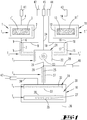
- the in the FIG. 1 only schematically illustrated device has a reactor 10, which is a gas-tight closed to the outside housing.
- the housing is evacuated by means of a drain 36 connected to a pump.
- an existing metal susceptor 35 are arranged in the cooling channels 27, with which the upper side of the configured as a cooling block susceptor 35 to a susceptor temperature T 6 of -50 to 10 ° C is temperature controlled.
- the upper side of the susceptor 35 forms the bottom of a process chamber 30, on which one or more substrates 20 are arranged.
- the ceiling of the process chamber 30 is formed by a gas outlet surface of a gas inlet member 31.
- the gas outlet surface of the gas inlet member 31 has a plurality of sieve-like and uniformly distributed over the entire gas outlet surface gas outlet openings 33, from which a process gas can flow into the process chamber 30.
- the gas inlet member 31 may be formed like a shower head.
- the process gas contains a gaseous starting material, which is at a temperature T 5 , which is above its condensation point, in the process chamber 30 is fed.
- the temperature of the surface of the substrate 20 is lower than the condensation temperature of the gaseous starting material, so that the gaseous starting material condenses on the upper side of the substrate 20 as a layer.
- a tempering device 32 is provided within the gas inlet member 31 .
- this tempering device 32 which is formed in the embodiment as a heater, the gaseous starting material to the temperature T 5 (gas inlet temperature) is controlled.
- the device has at least one source 1, in which a solid or liquid starting material 3 is kept ready.
- the starting material 3 is maintained at a source temperature T 1 which is greater than the gas inlet temperature T 5 .
- the starting material 3 may be stored as a porous body, a powder or the like.
- the starting material may also be an occupancy on a porous body.
- a source tempering device 2 is provided, which is a heater. With the heating heat is continuously fed into an evaporator 1 ', which includes the starting material 3, so that the starting material 3 is brought into the gas form.
- a solid starting material but also a liquid starting material can be used.
- a carrier gas feed line 4 opens into the evaporator 1 '.
- a carrier gas stream is fed into the evaporator 1' by means of a mass flow controller 41. These are argon, nitrogen, hydrogen or another inert gas.
- the converted into the gas form starting material 3 is transported through a gas outlet 6 from the evaporator 1 '.
- the Gausaustritt 6 is connected to a transport line 5, so that the gaseous starting material from the gas outlet 6 can be fed into the transport line 5.
- a dilution feed line 8 opens into the subsequent transport line 5.
- a diluent gas is fed into the gas line through the diluent gas line 8.
- the mass flow of the gas fed into the carrier gas feed line and the mass flow of the gas fed into the diluent gas line 8 are controlled by mass flow controllers 41, 42.
- the carrier gas stream transporting the gaseous starting material thus mixes with the dilution gas stream at the feed point 9, the diluent gas being the same gas which also forms the carrier gas stream.
- This line temperature control device 7 is designed as a heating sleeve. It heats the transport line 5 to a transport line temperature T 2 which is lower than the source temperature Z 1 .
- a second process gas source 11 which has a second evaporator 11 'which is likewise provided with a heating device 12, with which a liquid or solid starting material 13 is heated to a second source temperature T 1 '.
- the carrier gas transports the vaporized starting material out of the evaporator 11 'through a gas outlet 16.
- a diluent gas is fed into the gas stream. This is done by means of a diluent gas supply line 18 through which a mass flow of a diluent gas controlled by a mass flow controller 44 is fed.
- a transport line 15 Downstream of the feed point 19 extends a transport line 15 which is surrounded by a heating jacket, which forms a line heating 17, with which the transport line 15 is maintained at a line temperature T 2 '.
- the line temperature T 2 ' is lower than the cell temperature T 1 '.
- the starting material 13 are various organic materials.
- the transport line 5 and the transport line 15 open into a mixing device 21, are arranged in the Gasumlenkrion 23 to mix the entering from the transport lines 5.15 in the mixing device 21 gas mixtures with each other.
- a Mischertemperier sensible 22 is provided within the mixing device 21, a Mischertemperier sensible 22 is provided.
- This is a heating device with which the mixing device 21 and in particular the gas deflecting elements 23 are kept at a mixer temperature T 3 .
- the mixer temperature T 3 is less than the line temperatures T 2 , T 2 '.
- the gas mixture entering the mixing device 21, consisting of carrier gas and gaseous starting material further diluted.
- a further diluent gas feed line 24 opens into the mixing chamber of the mixer 21 upstream of the gas deflecting elements 23 and in particular upstream of the heating device 22.
- the dilution gas stream which is fed through the diluent gas feed line 24 into the mixing chamber is controlled by a mass flow controller 45.
- the mixed gas mixture in the mixing device 21 passes out of the mixing device 21 through a gas outlet 26.
- a gas outlet 26 There is another one Infeed point 29, at which a further diluent gas feed line 28 opens into the gas stream.
- a further diluent gas feed line 28 opens into the gas stream.
- another diluent gas stream which is controlled by a mass flow controller 46, is directed into the gas stream.
- the feed point 29 is located immediately downstream of the gas outlet 26.
- the transport line 25 extending downstream of the feed point 29 is heated by a heating collar 27 to a line temperature T 4 which is lower than the mixer temperature T 3 and greater than the temperature T 5 within the gas inlet element 31.
- the transport line 25 opens into the gas inlet member 31, in which a heater 32 is located. Upstream of the heating device 32, a diluent gas feed line 34 opens into the gas inlet element 31, through which a further diluent gas stream, which is controlled by a mass flow regulator 47, is fed into the gas inlet element 31. The gas stream fed into the gas inlet element 31 is thereby further diluted upstream of the heating device 32.
- the gradual dilution of the gaseous starting material in the gas line between source 1, 11 or evaporator 1 ', 11' and gas inlet member 31 leads to a gradual reduction of the partial pressure of the gaseous starting material or the gaseous starting materials within the gas line system in the flow direction.
- the temperature difference between the temperatures T 5 and T 6 may be greater than the remaining temperature steps.
- the FIG. 3 clarifies the control.
- the device has a control device 38, with which the temperatures T 1 , T 2 , T 1 ', T 2 ', T 3 , T 4 , T 5 and T 6 can be adjusted. This is done by means of regulators and control members, which supply the heating devices 2, 7, 12, 17, 22, 27, 32 with heating power.
- the temperatures T 1 , T 2 , T 1 ', T 2 ', T 3 , T 4 , T 5 and T 6 are measured by means of thermocouples and provided to the controller 38 for control.
- the control device supplies the cooling device 27 with cooling power.
- the control device is able to control the mass flow controllers 41-47 with which the carrier gas flows or dilution gas flows are regulated.
- a device which is characterized in that the first diluent gas supply line 8, 18 is arranged upstream of the line temperature control device 7, 17 and a further diluent gas supply line 34 opens upstream of the gas inlet temperature control device 32 into the gas inlet element 31 for feeding a diluent gas stream into the gas inlet element 31.
- a device characterized in that the first source temperature T 1 , T 1 'is greater than the line temperature T 2 , T 2 ', the line temperature T 2 , T 2 'is greater than the gas inlet temperature T 5 and the gas inlet temperature T 5 greater than the one susceptor temperature T 6
- a device which is characterized by a process gas source having a second evaporator 11 ', in which second evaporator 11' a solid or liquid second starting material by supplying heat generated by a second source tempering device 12 at a second source temperature T 1 'into a second gaseous starting material is vaporizable, wherein in the second evaporator 11 ', a second carrier gas supply line 14 opens for feeding a second carrier gas stream for transporting the second gaseous starting material from the second evaporator 11' in a second transport line 15, wherein the second transport line 15 with a second line temperature control device 17 on a second line temperature T 2 'is tempered and in the second transport line 15, a second diluent gas supply line 18 opens, through which a second diluent gas flow is fed into the second transport line 18, wherein the first transport line 8 and the two te transport line 18 open into a mixer 21, by means of a Mischertemperier sensible 22 is heated to a mixer temperature T 3 , where
- a device which is characterized in that the mixer temperature T 3 is less than the first and the second line temperature T 2 , T 2 'and is greater than the gas inlet temperature T 5 .
- a device which is characterized by a transport line 25 arranged downstream of the mixing device 21 and upstream of the gas inlet element 31 for transporting the gaseous starting material from the mixing device 21 into the gas inlet element 31, which can be temperature-controlled to a line temperature T 4 by means of a line temperature control device 27, upstream of the line Line tempering 27 a diluent gas supply line 28 into the transport line 25 opens for feeding a diluent gas into the transport line 25th
- a method characterized in that by feeding a plurality of diluent gas streams at various locations spaced from each other in the flow direction into a heated conduit connection between evaporator 1 ', 11' and gas inlet member 31, the partial pressure of the gaseous Starting material in the carrier gas stream is gradually reduced, wherein the line connection is heated so that at each point of the line connection, the temperature in the gas stream is greater than the condensation temperature of the gaseous starting material.
Landscapes
- Chemical & Material Sciences (AREA)
- Chemical Kinetics & Catalysis (AREA)
- Engineering & Computer Science (AREA)
- Materials Engineering (AREA)
- Mechanical Engineering (AREA)
- Metallurgy (AREA)
- Organic Chemistry (AREA)
- General Chemical & Material Sciences (AREA)
- Chemical Vapour Deposition (AREA)
- Feeding, Discharge, Calcimining, Fusing, And Gas-Generation Devices (AREA)
Claims (13)
- Dispositif de dépôt d'au moins une couche sur un substrat (20), le dispositif comprenant une source de gaz de traitement (1, 11) comportant un évaporateur (1', 11') dans lequel une matière de départ solide ou liquide peut être vaporisée en une matière de départ gazeuse par apport de chaleur, générée par un dispositif de régulation de température de source (2, 12), à une température de source (T1, T1'), un conduit d'alimentation en gaz porteur (4, 14) débouchant dans l'évaporateur (1', 11"), pour introduire un flux de gaz porteur destiné à transporter la matière de départ gazeuse de l'évaporateur (1', 11') dans un premier conduit de transport (5, 15), le premier conduit de transport (5, 15) pouvant être régulé à une température de conduit (T2, T2') au moyen d'un dispositif de régulation de température de conduit (7, 17), et un premier conduit de gaz de dilution (8, 18) débouchant dans le premier conduit de transport (5, 15) pour introduire un flux de gaz de dilution dans le premier conduit de transport (5, 15), le premier conduit d'alimentation en gaz de dilution (8, 18) étant disposé en amont du dispositif de régulation de température de conduit (7, 17), et un élément d'entrée de gaz (31) qui peut être régulé à une température d'entrée de gaz (T5) au moyen d'un dispositif de régulation de température d'entrée de gaz (32) et qui est raccordé au premier conduit de transport (8, 18), un autre conduit d'alimentation en gaz de dilution (34) débouchant dans l'élément d'entrée de gaz (31) en amont du dispositif de régulation de température d'entrée de gaz (32) pour introduire dans l'élément d'entrée de gaz (31) un flux de gaz de dilution avec lequel la matière de départ gazeuse peut être introduit dans une chambre de traitement (30) qui comporte un suscepteur (35) qui peut être régulé à une température de suscepteur (T6) au moyen d'un dispositif de régulation de température de suscepteur (27) de manière à permettre la croissance d'une couche sur le substrat (20), situé sur le suscepteur (35), au moyen de la matière de départ gazeuse et un dispositif de commande régulant le dispositif de régulation de température de source (2, 12) à la température de source (T1, T1'), le dispositif de régulation de température de conduit (7, 17) à la température de conduit (T2, T2'), le dispositif de régulation de température d'entrée de gaz (32) à la température d'entrée de gaz (T5) et le dispositif de régulation de température de suscepteur (27) à la température de suscepteur (T6), caractérisé en ce que le dispositif de commande est adapté de telle sorte que lors du dépôt de la couche, la température de la source (T1, T1') est supérieure à la température de conduit (T2, T2'), la température de conduit (T2, T2') est supérieure à la température d'entrée de gaz (T5) et la température d'entrée de gaz (T5) est supérieure à la température de suscepteur (T6).
- Procédé de dépôt d'au moins une couche sur au moins un substrat (20), au moyen d'une source de gaz de traitement (1, 11) comportant un évaporateur (1', 11') dans lequel une matière de départ solide ou liquide peut être vaporisée en une matière de départ gazeuse par apport de chaleur, générée par un dispositif de régulation de température de source (2, 12), à une température de source (T1, T1'), un conduit d'alimentation en gaz porteur (4, 14) débouchant dans l'évaporateur (1', 11"), conduit d'alimentation en gaz porteur dans lequel un flux de gaz porteur est introduit au moyen duquel la matière de départ gazeuse est transportée de l'évaporateur (1', 11') dans un premier conduit de transport (5, 15), le premier conduit de transport (5, 15) pouvant être régulé à une température de conduit (T2, T2') au moyen d'un dispositif de régulation de température de conduit (7, 17), et un premier conduit de gaz de dilution (8, 18) débouchant dans le premier conduit de transport (5, 15), lequel premier conduit de gaz de dilution permet d'introduire un flux de gaz de dilution dans le premier conduit de transport (5, 15), le premier conduit d'alimentation en gaz de dilution (8, 18) étant disposé en amont du dispositif de régulation de température de conduit (7, 17), et au moyen d'un élément d'entrée de gaz (31) qui peut être régulé à une température d'entrée de gaz (T5) au moyen d'un dispositif de régulation de température d'entrée de gaz (32) et qui est raccordé au premier conduit de transport (8, 18), un autre conduit d'alimentation en gaz de dilution (34) débouchant dans l'élément d'entrée de gaz (31) en amont du dispositif de régulation de température d'entrée de gaz (32) pour introduire dans l'élément d'entrée de gaz (31) un flux de gaz de dilution avec lequel la matière de départ gazeuse est introduite dans une chambre de traitement (30) qui comporte un suscepteur (35) qui peut être régulé à une température de suscepteur (T6) au moyen d'un dispositif de régulation de température de suscepteur (27), une couche étant déposée sur l'au moins un substrat (20), situé sur le suscepteur (35), au moyen de la matière de départ gazeuse, caractérisé en ce que, lors du dépôt de la couche, la température de la source (T1, T1') est supérieure à la température de conduit (T2, T2'), la température de conduit (T2, T2') est supérieure à la température d'entrée de gaz (T5) et la température d'entrée de gaz (T5) est supérieure à la température de suscepteur (T6) .
- Dispositif selon la revendication 1, caractérisé par une source de gaz de traitement comportant un deuxième évaporateur (11') dans lequel une deuxième matière de départ solide ou liquide peut être vaporisée en une deuxième matière de départ gazeuse par apport de chaleur, générée par un deuxième dispositif de régulation de température de source (12), à une deuxième température de source (T1'), un deuxième conduit d'alimentation en gaz porteur (14) débouchant dans le deuxième évaporateur (11') pour introduire un flux de gaz porteur destiné à transporter la deuxième matière de départ gazeuse du deuxième évaporateur (11') dans un deuxième conduit de transport (15), le deuxième conduit de transport (15) pouvant être régulé à une deuxième température de conduit (T2') au moyen d'un deuxième dispositif de régulation de température de conduit (17), et un deuxième conduit de gaz de dilution (18) débouchant dans le deuxième conduit de transport (15) pour introduire un flux de gaz de dilution dans le deuxième conduit de transport (15), le premier conduit de transport (8) et le deuxième conduit de transport (18) débouchant dans un mélangeur (21) qui est régulé à une température de mélangeur (T3) au moyen d'un dispositif de régulation de température de mélangeur (22), un conduit d'alimentation en gaz de dilution (24), permettant d'introduire un flux de gaz de dilution dans le dispositif de mélange (21), débouchant dans le dispositif de mélange (21) en amont du dispositif de régulation de température de mélangeur (22).
- Procédé selon la revendication 2, caractérisé par une source de gaz de traitement comportant un deuxième évaporateur (11') dans lequel une deuxième matière de départ solide ou liquide peut être vaporisée en une deuxième matière de départ gazeuse par apport de chaleur, générée par un deuxième dispositif de régulation de température de source (12), à une deuxième température de source (T1'), un deuxième conduit d'alimentation en gaz porteur (14) débouchant dans le deuxième évaporateur (11') pour introduire un flux de gaz porteur au moyen duquel la deuxième matière de départ gazeuse est transportée du deuxième évaporateur (11') dans un deuxième conduit de transport (15), le deuxième conduit de transport (15) pouvant être régulé à une deuxième température de conduit (T2') au moyen d'un deuxième dispositif de régulation de température de conduit (17), et un deuxième conduit de gaz de dilution (18) débouchant dans le deuxième conduit de transport (15) et permettant d'introduire un flux de gaz de dilution dans le deuxième conduit de transport (15), le premier conduit de transport (8) et le deuxième conduit de transport (18) débouchant dans un mélangeur (21) qui est régulé à une température de mélangeur (T3) au moyen d'un dispositif de régulation de température de mélangeur (22), un conduit d'alimentation en gaz de dilution (24), permettant d'introduire un flux de gaz de dilution dans le dispositif de mélange (21), débouchant dans le dispositif de mélange (21) en amont du dispositif de régulation de température de mélangeur (22).
- Dispositif selon la revendication 3, caractérisé en ce que la température de mélangeur (T3) est inférieure à la première et à la deuxième température de conduit (T2, T2') et est supérieure à la température d'entrée de gaz (T5).
- Procédé selon la revendication 4, caractérisé en ce que la température de mélangeur (T3) est inférieure à la première température et à la deuxième température de conduit (T2, T2') et est supérieure à la température d'entrée de gaz (T5).
- Dispositif selon la revendication 3, caractérisé par un conduit de transport (25) situé en aval du dispositif de mélange (21) et en amont de l'élément d'entrée de gaz (31) et destiné à transporter la matière de départ gazeuse du dispositif de mélange (21) dans l'élément d'entrée de gaz (31), lequel conduit de transport peut être régulé à une température de conduit (T4) au moyen d'un dispositif de régulation de température de conduit (27), un conduit d'alimentation en gaz de dilution (28) débouchant dans le conduit de transport (25) en amont du dispositif de régulation de température de conduit (27) pour introduire un flux de gaz de dilution dans le conduit de transport (25).
- Procédé selon la revendication 4, caractérisé par un conduit de transport (25) situé en aval du dispositif de mélange (21) et en amont de l'élément d'entrée de gaz (31) et destiné à transporter la matière de départ gazeuse du dispositif de mélange (21) dans l'élément d'entrée de gaz (31), lequel conduit de transport peut être régulé à une température de conduit (T4) au moyen d'un dispositif de régulation de température de conduit (27), un conduit d'alimentation en gaz de dilution (28) débouchant dans le conduit de transport (25) en amont du dispositif de régulation de température de conduit (27) et permettant d'introduire un flux de gaz de dilution dans le conduit de transport (25).
- Dispositif selon l'une des revendications 3, 5 ou 7, caractérisé en ce que la température de mélangeur (T3) est supérieure à la température de conduite (T4) et la température de conduit (T4) est supérieure à la température d'entrée de gaz (T5) .
- Procédé selon l'une des revendications 4, 6 ou 8, caractérisé en ce que la température de mélangeur (T3) est supérieure à la température de conduit (T4) et la température de conduit (T4) est supérieure à la température d'entrée de gaz (T5) .
- Procédé selon l'une des revendications 2, 4, 6, 8 ou 10, caractérisé en ce que l'alimentation d'une pluralité de flux de gaz de dilution, en différents emplacements espacés les unes des autres dans le sens d'écoulement, dans un raccordement de conduites chauffé situé entre l'évaporateur (1', 11') et l'élément d'entrée de gaz (31) permet de réduire par étapes la pression partielle de la matière de départ gazeuse dans le flux de gaz porteur, le raccordement étant chauffé de telle sorte que, chaque emplacement du raccordement de conduites, la température dans le flux de gaz est supérieure à la température de condensation de la matière de départ gazeuse.
- Dispositif selon l'une des revendications 1, 3, 5 ou 7, caractérisé en ce que les couches sont des couches organiques.
- Procédé selon l'une des revendications 2, 4, 6, 8, 10 ou 11, caractérisé en ce que les couches sont des couches organiques.
Applications Claiming Priority (2)
| Application Number | Priority Date | Filing Date | Title |
|---|---|---|---|
| DE102014115497.5A DE102014115497A1 (de) | 2014-10-24 | 2014-10-24 | Temperierte Gaszuleitung mit an mehreren Stellen eingespeisten Verdünnungsgasströmen |
| PCT/EP2015/072669 WO2016062514A1 (fr) | 2014-10-24 | 2015-10-01 | Conduite d'arrivée de gaz thermo-régulée comprenant des courants de gaz de dilution injectés à plusieurs endroits |
Publications (2)
| Publication Number | Publication Date |
|---|---|
| EP3209809A1 EP3209809A1 (fr) | 2017-08-30 |
| EP3209809B1 true EP3209809B1 (fr) | 2018-12-05 |
Family
ID=54325520
Family Applications (1)
| Application Number | Title | Priority Date | Filing Date |
|---|---|---|---|
| EP15781046.6A Active EP3209809B1 (fr) | 2014-10-24 | 2015-10-01 | Conduite d'arrivée de gaz thermo-régulée comprenant des courants de gaz de dilution injectés à plusieurs endroits |
Country Status (8)
| Country | Link |
|---|---|
| US (1) | US10472718B2 (fr) |
| EP (1) | EP3209809B1 (fr) |
| JP (1) | JP6688290B2 (fr) |
| KR (1) | KR20170072906A (fr) |
| CN (1) | CN107075660B (fr) |
| DE (1) | DE102014115497A1 (fr) |
| TW (1) | TWI668316B (fr) |
| WO (1) | WO2016062514A1 (fr) |
Families Citing this family (4)
| Publication number | Priority date | Publication date | Assignee | Title |
|---|---|---|---|---|
| DE102014115497A1 (de) * | 2014-10-24 | 2016-05-12 | Aixtron Se | Temperierte Gaszuleitung mit an mehreren Stellen eingespeisten Verdünnungsgasströmen |
| DE102016100625A1 (de) * | 2016-01-15 | 2017-07-20 | Aixtron Se | Vorrichtung zum Bereitstellen eines Prozessgases in einer Beschichtungseinrichtung |
| CN112048711A (zh) * | 2019-06-06 | 2020-12-08 | 北京北方华创微电子装备有限公司 | 一种供气管路和气相沉积设备 |
| JP2021031769A (ja) * | 2019-08-21 | 2021-03-01 | エーエスエム アイピー ホールディング ビー.ブイ. | 成膜原料混合ガス生成装置及び成膜装置 |
Family Cites Families (26)
| Publication number | Priority date | Publication date | Assignee | Title |
|---|---|---|---|---|
| JPH04295089A (ja) * | 1991-03-26 | 1992-10-20 | Kokusai Chodendo Sangyo Gijutsu Kenkyu Center | 酸化物超電導膜製造装置 |
| US5776254A (en) * | 1994-12-28 | 1998-07-07 | Mitsubishi Denki Kabushiki Kaisha | Apparatus for forming thin film by chemical vapor deposition |
| US5670218A (en) * | 1995-10-04 | 1997-09-23 | Hyundai Electronics Industries Co., Ltd. | Method for forming ferroelectric thin film and apparatus therefor |
| US6195504B1 (en) * | 1996-11-20 | 2001-02-27 | Ebara Corporation | Liquid feed vaporization system and gas injection device |
| JP3582437B2 (ja) * | 1999-12-24 | 2004-10-27 | 株式会社村田製作所 | 薄膜製造方法及びそれに用いる薄膜製造装置 |
| JP4778655B2 (ja) * | 2000-02-04 | 2011-09-21 | アイクストロン、アーゲー | 1つまたは多くの被膜を基板に沈積する方法および装置 |
| DE10007059A1 (de) | 2000-02-16 | 2001-08-23 | Aixtron Ag | Verfahren und Vorrichtung zur Herstellung von beschichteten Substraten mittels Kondensationsbeschichtung |
| DE10212923A1 (de) | 2002-03-22 | 2004-01-08 | Aixtron Ag | Verfahren zum Beschichten eines Substrates und Vorrichtung zur Durchführung des Verfahrens |
| JP2004349439A (ja) * | 2003-05-22 | 2004-12-09 | Renesas Technology Corp | 基板処理装置 |
| DE102004021578A1 (de) * | 2003-09-17 | 2005-04-21 | Aixtron Ag | Verfahren und Vorrichtung zur Abscheidung von ein-oder mehrkomponentigen Schichten und Schichtfolgen unter Verwendung von nicht-kontinuierlicher Injektion von flüssigen und gelösten Ausgangssubstanzen über eine Mehrkanalinjektionseinheit |
| JP4502189B2 (ja) * | 2004-06-02 | 2010-07-14 | ルネサスエレクトロニクス株式会社 | 薄膜の形成方法および半導体装置の製造方法 |
| CN101268210A (zh) * | 2005-09-20 | 2008-09-17 | 国立大学法人东北大学 | 成膜装置、蒸发夹具及测定方法 |
| JP5179739B2 (ja) | 2006-09-27 | 2013-04-10 | 東京エレクトロン株式会社 | 蒸着装置、蒸着装置の制御装置、蒸着装置の制御方法および蒸着装置の使用方法 |
| US7586109B2 (en) * | 2007-01-25 | 2009-09-08 | Varian Semiconductor Equipment Associates, Inc. | Technique for improving the performance and extending the lifetime of an ion source with gas dilution |
| DE102007011589A1 (de) * | 2007-03-08 | 2008-09-11 | Schott Ag | Fördereinrichtung für Precursor |
| US7794788B2 (en) * | 2007-03-28 | 2010-09-14 | Tokyo Electron Limited | Method for pre-conditioning a precursor vaporization system for a vapor deposition process |
| DE102008026974A1 (de) * | 2008-06-03 | 2009-12-10 | Aixtron Ag | Verfahren und Vorrichtung zum Abscheiden dünner Schichten aus polymeren Para-Xylylene oder substituiertem Para-Xylylene |
| DE102009003781A1 (de) * | 2008-06-03 | 2009-12-10 | Aixtron Ag | Verfahren zum Abscheiden eines dünnschichtigen Polymers in einer Niederdruckgasphase |
| JP2011063850A (ja) * | 2009-09-17 | 2011-03-31 | Tokyo Electron Ltd | 成膜装置、成膜方法および記憶媒体 |
| DE102011051261A1 (de) * | 2011-06-22 | 2012-12-27 | Aixtron Se | Verfahren und Vorrichtung zum Abscheiden von OLEDs insbesondere Verdampfungsvorrichtung dazu |
| WO2012175128A1 (fr) | 2011-06-22 | 2012-12-27 | Aixtron Se | Système de dépôt en phase vapeur et tête d'alimentation |
| JP5652960B2 (ja) * | 2011-08-01 | 2015-01-14 | 株式会社フジキン | 原料気化供給装置 |
| US9523151B2 (en) * | 2014-02-21 | 2016-12-20 | Tokyo Electron Limited | Vaporizer unit with open cell core and method of operating |
| DE102014115497A1 (de) * | 2014-10-24 | 2016-05-12 | Aixtron Se | Temperierte Gaszuleitung mit an mehreren Stellen eingespeisten Verdünnungsgasströmen |
| JP6565645B2 (ja) * | 2015-12-02 | 2019-08-28 | 東京エレクトロン株式会社 | 原料ガス供給装置、原料ガス供給方法及び記憶媒体 |
| JP6242933B2 (ja) * | 2016-03-31 | 2017-12-06 | 株式会社日立国際電気 | 基板処理装置、半導体装置の製造方法およびプログラム |
-
2014
- 2014-10-24 DE DE102014115497.5A patent/DE102014115497A1/de not_active Withdrawn
-
2015
- 2015-10-01 CN CN201580057372.0A patent/CN107075660B/zh active Active
- 2015-10-01 EP EP15781046.6A patent/EP3209809B1/fr active Active
- 2015-10-01 WO PCT/EP2015/072669 patent/WO2016062514A1/fr active Application Filing
- 2015-10-01 US US15/517,461 patent/US10472718B2/en active Active
- 2015-10-01 JP JP2017518109A patent/JP6688290B2/ja not_active Expired - Fee Related
- 2015-10-01 KR KR1020177012636A patent/KR20170072906A/ko not_active Application Discontinuation
- 2015-10-19 TW TW104134216A patent/TWI668316B/zh active
Non-Patent Citations (1)
| Title |
|---|
| None * |
Also Published As
| Publication number | Publication date |
|---|---|
| US20180265984A1 (en) | 2018-09-20 |
| JP2017537220A (ja) | 2017-12-14 |
| DE102014115497A1 (de) | 2016-05-12 |
| JP6688290B2 (ja) | 2020-04-28 |
| CN107075660B (zh) | 2019-06-04 |
| TWI668316B (zh) | 2019-08-11 |
| EP3209809A1 (fr) | 2017-08-30 |
| WO2016062514A1 (fr) | 2016-04-28 |
| TW201623661A (zh) | 2016-07-01 |
| KR20170072906A (ko) | 2017-06-27 |
| CN107075660A (zh) | 2017-08-18 |
| US10472718B2 (en) | 2019-11-12 |
Similar Documents
| Publication | Publication Date | Title |
|---|---|---|
| EP3209809B1 (fr) | Conduite d'arrivée de gaz thermo-régulée comprenant des courants de gaz de dilution injectés à plusieurs endroits | |
| EP1774057B1 (fr) | Dispositif et procede de depot chimique en phase vapeur a haut rendement | |
| EP1252363B1 (fr) | Dispositif et procede pour deposer une ou plusieurs couches sur un substrat | |
| EP2470684B1 (fr) | Procédé cvd et réacteur cvd | |
| DE69433656T2 (de) | Verfahren zum Einleiten reaktiven Gases in eine Substratbearbeitungsvorrichtung | |
| DE102014104218A1 (de) | CVD-Reaktor mit Vorlaufzonen-Temperaturregelung | |
| DE102006044626B4 (de) | Aufkohlungsbehandlungsvorrichtung und -verfahren | |
| DE102011089501B4 (de) | Vorrichtung und Verfahren zum Verdampfen von Material aus einer Metallschmelze | |
| WO2016000944A1 (fr) | Procédé et dispositif de génération de la vapeur à partir de plusieurs matières de départ liquides ou solides pour dispositif cvd ou pvd | |
| EP1364076B1 (fr) | Procede et dispositif pour alimenter un reacteur de depot chimique en phase vapeur en materiau de base, passe de la phase liquide a la phase gazeuse | |
| WO2012143257A1 (fr) | Dispositif et procédé de dépôt de couches semi-conductrices sous apport de hcl pour éliminer la croissance parasitaire | |
| EP3523466A1 (fr) | Dispositif et procédé d'application d'une couche de carbone | |
| DE10212923A1 (de) | Verfahren zum Beschichten eines Substrates und Vorrichtung zur Durchführung des Verfahrens | |
| WO2011098420A1 (fr) | Organe d'admission de gaz muni d'un ensemble plaques de déviation | |
| EP1007761B1 (fr) | Systeme de conduite de gaz pour reacteur industriel et procede de traitement de substrats a semi-conducteurs | |
| EP4211290A2 (fr) | Réacteur cvd présentant une zone d'entrée de gaz thermo-régulable | |
| DE102006013801A1 (de) | Gaseinlassorgan mit gelochter Isolationsplatte | |
| WO2017121704A1 (fr) | Dispositif de fourniture d'un gaz de traitement dans un dispositif de revêtement | |
| DE102019217284A1 (de) | Dampfphasenabscheidungsvorrichtung | |
| DE102006023046B4 (de) | Verfahren und Ausgangsmaterial zum Bereitstellen eines gasförmigen Precursors | |
| DE102013109696B3 (de) | Beschichtungsverfahren und Beschichtungsvorrichtung | |
| EP3224385B1 (fr) | Dispositif pour déposer une couche sur un substrat | |
| DE102010036332A1 (de) | Verfahren zum Beschichten eines Substrats mittels eines Lichtbogens | |
| EP1393360A1 (fr) | Procede et dispositif pour le traitement thermique de courte duree d'objets plats | |
| DE102021200421A1 (de) | Sprüheinheit und Verfahren zum Aufsprühen eines aus einem Festkörper gewonnenen Materials |
Legal Events
| Date | Code | Title | Description |
|---|---|---|---|
| STAA | Information on the status of an ep patent application or granted ep patent |
Free format text: STATUS: THE INTERNATIONAL PUBLICATION HAS BEEN MADE |
|
| PUAI | Public reference made under article 153(3) epc to a published international application that has entered the european phase |
Free format text: ORIGINAL CODE: 0009012 |
|
| STAA | Information on the status of an ep patent application or granted ep patent |
Free format text: STATUS: REQUEST FOR EXAMINATION WAS MADE |
|
| 17P | Request for examination filed |
Effective date: 20170505 |
|
| AK | Designated contracting states |
Kind code of ref document: A1 Designated state(s): AL AT BE BG CH CY CZ DE DK EE ES FI FR GB GR HR HU IE IS IT LI LT LU LV MC MK MT NL NO PL PT RO RS SE SI SK SM TR |
|
| AX | Request for extension of the european patent |
Extension state: BA ME |
|
| RIN1 | Information on inventor provided before grant (corrected) |
Inventor name: GERSDORFF, MARKUS Inventor name: LONG, MICHAEL Inventor name: DAUELSBERG, MARTIN Inventor name: PAGADALA GOPI, BASKAR |
|
| DAV | Request for validation of the european patent (deleted) | ||
| DAX | Request for extension of the european patent (deleted) | ||
| GRAP | Despatch of communication of intention to grant a patent |
Free format text: ORIGINAL CODE: EPIDOSNIGR1 |
|
| STAA | Information on the status of an ep patent application or granted ep patent |
Free format text: STATUS: GRANT OF PATENT IS INTENDED |
|
| INTG | Intention to grant announced |
Effective date: 20180425 |
|
| GRAS | Grant fee paid |
Free format text: ORIGINAL CODE: EPIDOSNIGR3 |
|
| GRAA | (expected) grant |
Free format text: ORIGINAL CODE: 0009210 |
|
| STAA | Information on the status of an ep patent application or granted ep patent |
Free format text: STATUS: THE PATENT HAS BEEN GRANTED |
|
| AK | Designated contracting states |
Kind code of ref document: B1 Designated state(s): AL AT BE BG CH CY CZ DE DK EE ES FI FR GB GR HR HU IE IS IT LI LT LU LV MC MK MT NL NO PL PT RO RS SE SI SK SM TR |
|
| REG | Reference to a national code |
Ref country code: GB Ref legal event code: FG4D Free format text: NOT ENGLISH |
|
| REG | Reference to a national code |
Ref country code: CH Ref legal event code: EP |
|
| REG | Reference to a national code |
Ref country code: AT Ref legal event code: REF Ref document number: 1073159 Country of ref document: AT Kind code of ref document: T Effective date: 20181215 |
|
| REG | Reference to a national code |
Ref country code: IE Ref legal event code: FG4D Free format text: LANGUAGE OF EP DOCUMENT: GERMAN |
|
| REG | Reference to a national code |
Ref country code: DE Ref legal event code: R096 Ref document number: 502015007138 Country of ref document: DE |
|
| REG | Reference to a national code |
Ref country code: NL Ref legal event code: FP |
|
| REG | Reference to a national code |
Ref country code: LT Ref legal event code: MG4D |
|
| PG25 | Lapsed in a contracting state [announced via postgrant information from national office to epo] |
Ref country code: ES Free format text: LAPSE BECAUSE OF FAILURE TO SUBMIT A TRANSLATION OF THE DESCRIPTION OR TO PAY THE FEE WITHIN THE PRESCRIBED TIME-LIMIT Effective date: 20181205 Ref country code: LV Free format text: LAPSE BECAUSE OF FAILURE TO SUBMIT A TRANSLATION OF THE DESCRIPTION OR TO PAY THE FEE WITHIN THE PRESCRIBED TIME-LIMIT Effective date: 20181205 Ref country code: HR Free format text: LAPSE BECAUSE OF FAILURE TO SUBMIT A TRANSLATION OF THE DESCRIPTION OR TO PAY THE FEE WITHIN THE PRESCRIBED TIME-LIMIT Effective date: 20181205 Ref country code: BG Free format text: LAPSE BECAUSE OF FAILURE TO SUBMIT A TRANSLATION OF THE DESCRIPTION OR TO PAY THE FEE WITHIN THE PRESCRIBED TIME-LIMIT Effective date: 20190305 Ref country code: LT Free format text: LAPSE BECAUSE OF FAILURE TO SUBMIT A TRANSLATION OF THE DESCRIPTION OR TO PAY THE FEE WITHIN THE PRESCRIBED TIME-LIMIT Effective date: 20181205 Ref country code: NO Free format text: LAPSE BECAUSE OF FAILURE TO SUBMIT A TRANSLATION OF THE DESCRIPTION OR TO PAY THE FEE WITHIN THE PRESCRIBED TIME-LIMIT Effective date: 20190305 |
|
| PG25 | Lapsed in a contracting state [announced via postgrant information from national office to epo] |
Ref country code: SE Free format text: LAPSE BECAUSE OF FAILURE TO SUBMIT A TRANSLATION OF THE DESCRIPTION OR TO PAY THE FEE WITHIN THE PRESCRIBED TIME-LIMIT Effective date: 20181205 Ref country code: AL Free format text: LAPSE BECAUSE OF FAILURE TO SUBMIT A TRANSLATION OF THE DESCRIPTION OR TO PAY THE FEE WITHIN THE PRESCRIBED TIME-LIMIT Effective date: 20181205 Ref country code: GR Free format text: LAPSE BECAUSE OF FAILURE TO SUBMIT A TRANSLATION OF THE DESCRIPTION OR TO PAY THE FEE WITHIN THE PRESCRIBED TIME-LIMIT Effective date: 20190306 Ref country code: RS Free format text: LAPSE BECAUSE OF FAILURE TO SUBMIT A TRANSLATION OF THE DESCRIPTION OR TO PAY THE FEE WITHIN THE PRESCRIBED TIME-LIMIT Effective date: 20181205 |
|
| PG25 | Lapsed in a contracting state [announced via postgrant information from national office to epo] |
Ref country code: PT Free format text: LAPSE BECAUSE OF FAILURE TO SUBMIT A TRANSLATION OF THE DESCRIPTION OR TO PAY THE FEE WITHIN THE PRESCRIBED TIME-LIMIT Effective date: 20190405 Ref country code: IT Free format text: LAPSE BECAUSE OF FAILURE TO SUBMIT A TRANSLATION OF THE DESCRIPTION OR TO PAY THE FEE WITHIN THE PRESCRIBED TIME-LIMIT Effective date: 20181205 Ref country code: CZ Free format text: LAPSE BECAUSE OF FAILURE TO SUBMIT A TRANSLATION OF THE DESCRIPTION OR TO PAY THE FEE WITHIN THE PRESCRIBED TIME-LIMIT Effective date: 20181205 Ref country code: PL Free format text: LAPSE BECAUSE OF FAILURE TO SUBMIT A TRANSLATION OF THE DESCRIPTION OR TO PAY THE FEE WITHIN THE PRESCRIBED TIME-LIMIT Effective date: 20181205 |
|
| PG25 | Lapsed in a contracting state [announced via postgrant information from national office to epo] |
Ref country code: IS Free format text: LAPSE BECAUSE OF FAILURE TO SUBMIT A TRANSLATION OF THE DESCRIPTION OR TO PAY THE FEE WITHIN THE PRESCRIBED TIME-LIMIT Effective date: 20190405 Ref country code: SK Free format text: LAPSE BECAUSE OF FAILURE TO SUBMIT A TRANSLATION OF THE DESCRIPTION OR TO PAY THE FEE WITHIN THE PRESCRIBED TIME-LIMIT Effective date: 20181205 Ref country code: RO Free format text: LAPSE BECAUSE OF FAILURE TO SUBMIT A TRANSLATION OF THE DESCRIPTION OR TO PAY THE FEE WITHIN THE PRESCRIBED TIME-LIMIT Effective date: 20181205 Ref country code: EE Free format text: LAPSE BECAUSE OF FAILURE TO SUBMIT A TRANSLATION OF THE DESCRIPTION OR TO PAY THE FEE WITHIN THE PRESCRIBED TIME-LIMIT Effective date: 20181205 Ref country code: SM Free format text: LAPSE BECAUSE OF FAILURE TO SUBMIT A TRANSLATION OF THE DESCRIPTION OR TO PAY THE FEE WITHIN THE PRESCRIBED TIME-LIMIT Effective date: 20181205 |
|
| REG | Reference to a national code |
Ref country code: DE Ref legal event code: R097 Ref document number: 502015007138 Country of ref document: DE |
|
| PLBE | No opposition filed within time limit |
Free format text: ORIGINAL CODE: 0009261 |
|
| STAA | Information on the status of an ep patent application or granted ep patent |
Free format text: STATUS: NO OPPOSITION FILED WITHIN TIME LIMIT |
|
| PG25 | Lapsed in a contracting state [announced via postgrant information from national office to epo] |
Ref country code: SI Free format text: LAPSE BECAUSE OF FAILURE TO SUBMIT A TRANSLATION OF THE DESCRIPTION OR TO PAY THE FEE WITHIN THE PRESCRIBED TIME-LIMIT Effective date: 20181205 Ref country code: DK Free format text: LAPSE BECAUSE OF FAILURE TO SUBMIT A TRANSLATION OF THE DESCRIPTION OR TO PAY THE FEE WITHIN THE PRESCRIBED TIME-LIMIT Effective date: 20181205 |
|
| 26N | No opposition filed |
Effective date: 20190906 |
|
| PG25 | Lapsed in a contracting state [announced via postgrant information from national office to epo] |
Ref country code: TR Free format text: LAPSE BECAUSE OF FAILURE TO SUBMIT A TRANSLATION OF THE DESCRIPTION OR TO PAY THE FEE WITHIN THE PRESCRIBED TIME-LIMIT Effective date: 20181205 |
|
| REG | Reference to a national code |
Ref country code: FI Ref legal event code: MAE |
|
| PG25 | Lapsed in a contracting state [announced via postgrant information from national office to epo] |
Ref country code: MC Free format text: LAPSE BECAUSE OF FAILURE TO SUBMIT A TRANSLATION OF THE DESCRIPTION OR TO PAY THE FEE WITHIN THE PRESCRIBED TIME-LIMIT Effective date: 20181205 |
|
| REG | Reference to a national code |
Ref country code: CH Ref legal event code: PL |
|
| REG | Reference to a national code |
Ref country code: NL Ref legal event code: MM Effective date: 20191101 |
|
| PG25 | Lapsed in a contracting state [announced via postgrant information from national office to epo] |
Ref country code: FI Free format text: LAPSE BECAUSE OF NON-PAYMENT OF DUE FEES Effective date: 20191001 Ref country code: LU Free format text: LAPSE BECAUSE OF NON-PAYMENT OF DUE FEES Effective date: 20191001 Ref country code: CH Free format text: LAPSE BECAUSE OF NON-PAYMENT OF DUE FEES Effective date: 20191031 Ref country code: LI Free format text: LAPSE BECAUSE OF NON-PAYMENT OF DUE FEES Effective date: 20191031 |
|
| REG | Reference to a national code |
Ref country code: BE Ref legal event code: MM Effective date: 20191031 |
|
| PG25 | Lapsed in a contracting state [announced via postgrant information from national office to epo] |
Ref country code: NL Free format text: LAPSE BECAUSE OF NON-PAYMENT OF DUE FEES Effective date: 20191101 Ref country code: BE Free format text: LAPSE BECAUSE OF NON-PAYMENT OF DUE FEES Effective date: 20191031 |
|
| GBPC | Gb: european patent ceased through non-payment of renewal fee |
Effective date: 20191001 |
|
| PG25 | Lapsed in a contracting state [announced via postgrant information from national office to epo] |
Ref country code: GB Free format text: LAPSE BECAUSE OF NON-PAYMENT OF DUE FEES Effective date: 20191001 Ref country code: IE Free format text: LAPSE BECAUSE OF NON-PAYMENT OF DUE FEES Effective date: 20191001 Ref country code: FR Free format text: LAPSE BECAUSE OF NON-PAYMENT OF DUE FEES Effective date: 20191031 |
|
| PG25 | Lapsed in a contracting state [announced via postgrant information from national office to epo] |
Ref country code: CY Free format text: LAPSE BECAUSE OF FAILURE TO SUBMIT A TRANSLATION OF THE DESCRIPTION OR TO PAY THE FEE WITHIN THE PRESCRIBED TIME-LIMIT Effective date: 20181205 |
|
| PG25 | Lapsed in a contracting state [announced via postgrant information from national office to epo] |
Ref country code: MT Free format text: LAPSE BECAUSE OF FAILURE TO SUBMIT A TRANSLATION OF THE DESCRIPTION OR TO PAY THE FEE WITHIN THE PRESCRIBED TIME-LIMIT Effective date: 20181205 Ref country code: HU Free format text: LAPSE BECAUSE OF FAILURE TO SUBMIT A TRANSLATION OF THE DESCRIPTION OR TO PAY THE FEE WITHIN THE PRESCRIBED TIME-LIMIT; INVALID AB INITIO Effective date: 20151001 |
|
| REG | Reference to a national code |
Ref country code: AT Ref legal event code: MM01 Ref document number: 1073159 Country of ref document: AT Kind code of ref document: T Effective date: 20201001 |
|
| PG25 | Lapsed in a contracting state [announced via postgrant information from national office to epo] |
Ref country code: AT Free format text: LAPSE BECAUSE OF NON-PAYMENT OF DUE FEES Effective date: 20201001 |
|
| PG25 | Lapsed in a contracting state [announced via postgrant information from national office to epo] |
Ref country code: MK Free format text: LAPSE BECAUSE OF FAILURE TO SUBMIT A TRANSLATION OF THE DESCRIPTION OR TO PAY THE FEE WITHIN THE PRESCRIBED TIME-LIMIT Effective date: 20181205 |
|
| P01 | Opt-out of the competence of the unified patent court (upc) registered |
Effective date: 20230528 |
|
| PGFP | Annual fee paid to national office [announced via postgrant information from national office to epo] |
Ref country code: DE Payment date: 20231120 Year of fee payment: 9 |