EP3209236B1 - Vorrichtung zur abgabe gepulster rf-energie bei der katheterablation - Google Patents
Vorrichtung zur abgabe gepulster rf-energie bei der katheterablation Download PDFInfo
- Publication number
- EP3209236B1 EP3209236B1 EP16716145.4A EP16716145A EP3209236B1 EP 3209236 B1 EP3209236 B1 EP 3209236B1 EP 16716145 A EP16716145 A EP 16716145A EP 3209236 B1 EP3209236 B1 EP 3209236B1
- Authority
- EP
- European Patent Office
- Prior art keywords
- tip
- temperature
- ablation
- catheter
- generator
- Prior art date
- Legal status (The legal status is an assumption and is not a legal conclusion. Google has not performed a legal analysis and makes no representation as to the accuracy of the status listed.)
- Active
Links
- 238000013153 catheter ablation Methods 0.000 title claims description 12
- 238000002679 ablation Methods 0.000 claims description 96
- 238000000034 method Methods 0.000 claims description 32
- 230000004044 response Effects 0.000 claims description 7
- 238000004891 communication Methods 0.000 claims description 3
- 230000000541 pulsatile effect Effects 0.000 claims description 2
- 230000000630 rising effect Effects 0.000 claims 1
- BASFCYQUMIYNBI-UHFFFAOYSA-N platinum Chemical compound [Pt] BASFCYQUMIYNBI-UHFFFAOYSA-N 0.000 description 40
- 230000002262 irrigation Effects 0.000 description 39
- 238000003973 irrigation Methods 0.000 description 39
- 239000010410 layer Substances 0.000 description 32
- 230000008867 communication pathway Effects 0.000 description 22
- 229910052697 platinum Inorganic materials 0.000 description 20
- 239000000463 material Substances 0.000 description 12
- 230000008569 process Effects 0.000 description 11
- 230000003902 lesion Effects 0.000 description 10
- 230000005291 magnetic effect Effects 0.000 description 10
- 239000000126 substance Substances 0.000 description 10
- PCHJSUWPFVWCPO-UHFFFAOYSA-N gold Chemical compound [Au] PCHJSUWPFVWCPO-UHFFFAOYSA-N 0.000 description 9
- 229910052737 gold Inorganic materials 0.000 description 9
- 239000010931 gold Substances 0.000 description 9
- 230000008901 benefit Effects 0.000 description 8
- WABPQHHGFIMREM-UHFFFAOYSA-N lead(0) Chemical compound [Pb] WABPQHHGFIMREM-UHFFFAOYSA-N 0.000 description 8
- HWLDNSXPUQTBOD-UHFFFAOYSA-N platinum-iridium alloy Chemical compound [Ir].[Pt] HWLDNSXPUQTBOD-UHFFFAOYSA-N 0.000 description 8
- 239000007787 solid Substances 0.000 description 8
- 239000000853 adhesive Substances 0.000 description 6
- 230000001070 adhesive effect Effects 0.000 description 6
- 229910052797 bismuth Inorganic materials 0.000 description 6
- 238000010276 construction Methods 0.000 description 6
- 230000004907 flux Effects 0.000 description 6
- 239000002907 paramagnetic material Substances 0.000 description 6
- JCXGWMGPZLAOME-UHFFFAOYSA-N bismuth atom Chemical compound [Bi] JCXGWMGPZLAOME-UHFFFAOYSA-N 0.000 description 5
- 239000002889 diamagnetic material Substances 0.000 description 5
- 238000004519 manufacturing process Methods 0.000 description 5
- 238000003466 welding Methods 0.000 description 5
- 238000013459 approach Methods 0.000 description 4
- 230000005292 diamagnetic effect Effects 0.000 description 4
- 230000005298 paramagnetic effect Effects 0.000 description 4
- 230000037361 pathway Effects 0.000 description 4
- 239000008280 blood Substances 0.000 description 3
- 210000004369 blood Anatomy 0.000 description 3
- 230000000295 complement effect Effects 0.000 description 3
- 238000012544 monitoring process Methods 0.000 description 3
- 230000035699 permeability Effects 0.000 description 3
- 229920000642 polymer Polymers 0.000 description 3
- 229910052709 silver Inorganic materials 0.000 description 3
- 239000004332 silver Substances 0.000 description 3
- 239000002356 single layer Substances 0.000 description 3
- 238000005476 soldering Methods 0.000 description 3
- 238000012546 transfer Methods 0.000 description 3
- 230000007704 transition Effects 0.000 description 3
- 238000012935 Averaging Methods 0.000 description 2
- 239000004696 Poly ether ether ketone Substances 0.000 description 2
- 230000009286 beneficial effect Effects 0.000 description 2
- 239000000919 ceramic Substances 0.000 description 2
- 230000009977 dual effect Effects 0.000 description 2
- 230000005294 ferromagnetic effect Effects 0.000 description 2
- 230000000977 initiatory effect Effects 0.000 description 2
- 229910052752 metalloid Inorganic materials 0.000 description 2
- 150000002738 metalloids Chemical class 0.000 description 2
- 238000013021 overheating Methods 0.000 description 2
- 239000004033 plastic Substances 0.000 description 2
- 229920003023 plastic Polymers 0.000 description 2
- 229920002530 polyetherether ketone Polymers 0.000 description 2
- 238000004382 potting Methods 0.000 description 2
- 238000012545 processing Methods 0.000 description 2
- RYGMFSIKBFXOCR-UHFFFAOYSA-N Copper Chemical compound [Cu] RYGMFSIKBFXOCR-UHFFFAOYSA-N 0.000 description 1
- 239000004642 Polyimide Substances 0.000 description 1
- XUIMIQQOPSSXEZ-UHFFFAOYSA-N Silicon Chemical compound [Si] XUIMIQQOPSSXEZ-UHFFFAOYSA-N 0.000 description 1
- 229920004738 ULTEM® Polymers 0.000 description 1
- 230000002159 abnormal effect Effects 0.000 description 1
- 238000009825 accumulation Methods 0.000 description 1
- 230000009471 action Effects 0.000 description 1
- 239000000956 alloy Substances 0.000 description 1
- 229910045601 alloy Inorganic materials 0.000 description 1
- 230000004075 alteration Effects 0.000 description 1
- JUPQTSLXMOCDHR-UHFFFAOYSA-N benzene-1,4-diol;bis(4-fluorophenyl)methanone Chemical compound OC1=CC=C(O)C=C1.C1=CC(F)=CC=C1C(=O)C1=CC=C(F)C=C1 JUPQTSLXMOCDHR-UHFFFAOYSA-N 0.000 description 1
- 230000017531 blood circulation Effects 0.000 description 1
- 229910010293 ceramic material Inorganic materials 0.000 description 1
- 230000008859 change Effects 0.000 description 1
- 229910052802 copper Inorganic materials 0.000 description 1
- 239000010949 copper Substances 0.000 description 1
- 230000001419 dependent effect Effects 0.000 description 1
- 238000013461 design Methods 0.000 description 1
- 210000003238 esophagus Anatomy 0.000 description 1
- 230000001747 exhibiting effect Effects 0.000 description 1
- 238000005242 forging Methods 0.000 description 1
- 229910052732 germanium Inorganic materials 0.000 description 1
- GNPVGFCGXDBREM-UHFFFAOYSA-N germanium atom Chemical compound [Ge] GNPVGFCGXDBREM-UHFFFAOYSA-N 0.000 description 1
- 230000017525 heat dissipation Effects 0.000 description 1
- 238000003754 machining Methods 0.000 description 1
- 230000000116 mitigating effect Effects 0.000 description 1
- 239000000203 mixture Substances 0.000 description 1
- 238000012986 modification Methods 0.000 description 1
- 230000004048 modification Effects 0.000 description 1
- 229920001721 polyimide Polymers 0.000 description 1
- 229910001848 post-transition metal Inorganic materials 0.000 description 1
- 239000010970 precious metal Substances 0.000 description 1
- 230000009467 reduction Effects 0.000 description 1
- 230000000284 resting effect Effects 0.000 description 1
- 230000033764 rhythmic process Effects 0.000 description 1
- 238000005096 rolling process Methods 0.000 description 1
- 230000035945 sensitivity Effects 0.000 description 1
- 229910052710 silicon Inorganic materials 0.000 description 1
- 239000010703 silicon Substances 0.000 description 1
- 238000009987 spinning Methods 0.000 description 1
- 230000008542 thermal sensitivity Effects 0.000 description 1
- 238000004861 thermometry Methods 0.000 description 1
Images


Classifications
-
- A—HUMAN NECESSITIES
- A61—MEDICAL OR VETERINARY SCIENCE; HYGIENE
- A61B—DIAGNOSIS; SURGERY; IDENTIFICATION
- A61B18/00—Surgical instruments, devices or methods for transferring non-mechanical forms of energy to or from the body
- A61B18/04—Surgical instruments, devices or methods for transferring non-mechanical forms of energy to or from the body by heating
- A61B18/12—Surgical instruments, devices or methods for transferring non-mechanical forms of energy to or from the body by heating by passing a current through the tissue to be heated, e.g. high-frequency current
- A61B18/14—Probes or electrodes therefor
- A61B18/1492—Probes or electrodes therefor having a flexible, catheter-like structure, e.g. for heart ablation
-
- A—HUMAN NECESSITIES
- A61—MEDICAL OR VETERINARY SCIENCE; HYGIENE
- A61B—DIAGNOSIS; SURGERY; IDENTIFICATION
- A61B18/00—Surgical instruments, devices or methods for transferring non-mechanical forms of energy to or from the body
- A61B18/04—Surgical instruments, devices or methods for transferring non-mechanical forms of energy to or from the body by heating
- A61B18/12—Surgical instruments, devices or methods for transferring non-mechanical forms of energy to or from the body by heating by passing a current through the tissue to be heated, e.g. high-frequency current
- A61B18/1206—Generators therefor
- A61B18/1233—Generators therefor with circuits for assuring patient safety
-
- A—HUMAN NECESSITIES
- A61—MEDICAL OR VETERINARY SCIENCE; HYGIENE
- A61B—DIAGNOSIS; SURGERY; IDENTIFICATION
- A61B18/00—Surgical instruments, devices or methods for transferring non-mechanical forms of energy to or from the body
- A61B2018/00005—Cooling or heating of the probe or tissue immediately surrounding the probe
- A61B2018/00011—Cooling or heating of the probe or tissue immediately surrounding the probe with fluids
- A61B2018/00029—Cooling or heating of the probe or tissue immediately surrounding the probe with fluids open
-
- A—HUMAN NECESSITIES
- A61—MEDICAL OR VETERINARY SCIENCE; HYGIENE
- A61B—DIAGNOSIS; SURGERY; IDENTIFICATION
- A61B18/00—Surgical instruments, devices or methods for transferring non-mechanical forms of energy to or from the body
- A61B2018/00053—Mechanical features of the instrument of device
- A61B2018/00059—Material properties
- A61B2018/00071—Electrical conductivity
- A61B2018/00077—Electrical conductivity high, i.e. electrically conducting
-
- A—HUMAN NECESSITIES
- A61—MEDICAL OR VETERINARY SCIENCE; HYGIENE
- A61B—DIAGNOSIS; SURGERY; IDENTIFICATION
- A61B18/00—Surgical instruments, devices or methods for transferring non-mechanical forms of energy to or from the body
- A61B2018/00053—Mechanical features of the instrument of device
- A61B2018/00059—Material properties
- A61B2018/00071—Electrical conductivity
- A61B2018/00083—Electrical conductivity low, i.e. electrically insulating
-
- A—HUMAN NECESSITIES
- A61—MEDICAL OR VETERINARY SCIENCE; HYGIENE
- A61B—DIAGNOSIS; SURGERY; IDENTIFICATION
- A61B18/00—Surgical instruments, devices or methods for transferring non-mechanical forms of energy to or from the body
- A61B2018/00053—Mechanical features of the instrument of device
- A61B2018/00059—Material properties
- A61B2018/00089—Thermal conductivity
- A61B2018/00095—Thermal conductivity high, i.e. heat conducting
-
- A—HUMAN NECESSITIES
- A61—MEDICAL OR VETERINARY SCIENCE; HYGIENE
- A61B—DIAGNOSIS; SURGERY; IDENTIFICATION
- A61B18/00—Surgical instruments, devices or methods for transferring non-mechanical forms of energy to or from the body
- A61B2018/00053—Mechanical features of the instrument of device
- A61B2018/00059—Material properties
- A61B2018/00089—Thermal conductivity
- A61B2018/00101—Thermal conductivity low, i.e. thermally insulating
-
- A—HUMAN NECESSITIES
- A61—MEDICAL OR VETERINARY SCIENCE; HYGIENE
- A61B—DIAGNOSIS; SURGERY; IDENTIFICATION
- A61B18/00—Surgical instruments, devices or methods for transferring non-mechanical forms of energy to or from the body
- A61B2018/00315—Surgical instruments, devices or methods for transferring non-mechanical forms of energy to or from the body for treatment of particular body parts
- A61B2018/00345—Vascular system
- A61B2018/00351—Heart
-
- A—HUMAN NECESSITIES
- A61—MEDICAL OR VETERINARY SCIENCE; HYGIENE
- A61B—DIAGNOSIS; SURGERY; IDENTIFICATION
- A61B18/00—Surgical instruments, devices or methods for transferring non-mechanical forms of energy to or from the body
- A61B2018/00571—Surgical instruments, devices or methods for transferring non-mechanical forms of energy to or from the body for achieving a particular surgical effect
- A61B2018/00577—Ablation
-
- A—HUMAN NECESSITIES
- A61—MEDICAL OR VETERINARY SCIENCE; HYGIENE
- A61B—DIAGNOSIS; SURGERY; IDENTIFICATION
- A61B18/00—Surgical instruments, devices or methods for transferring non-mechanical forms of energy to or from the body
- A61B2018/00636—Sensing and controlling the application of energy
- A61B2018/00642—Sensing and controlling the application of energy with feedback, i.e. closed loop control
-
- A—HUMAN NECESSITIES
- A61—MEDICAL OR VETERINARY SCIENCE; HYGIENE
- A61B—DIAGNOSIS; SURGERY; IDENTIFICATION
- A61B18/00—Surgical instruments, devices or methods for transferring non-mechanical forms of energy to or from the body
- A61B2018/00636—Sensing and controlling the application of energy
- A61B2018/00666—Sensing and controlling the application of energy using a threshold value
- A61B2018/00678—Sensing and controlling the application of energy using a threshold value upper
-
- A—HUMAN NECESSITIES
- A61—MEDICAL OR VETERINARY SCIENCE; HYGIENE
- A61B—DIAGNOSIS; SURGERY; IDENTIFICATION
- A61B18/00—Surgical instruments, devices or methods for transferring non-mechanical forms of energy to or from the body
- A61B2018/00636—Sensing and controlling the application of energy
- A61B2018/00696—Controlled or regulated parameters
- A61B2018/00702—Power or energy
- A61B2018/00708—Power or energy switching the power on or off
-
- A—HUMAN NECESSITIES
- A61—MEDICAL OR VETERINARY SCIENCE; HYGIENE
- A61B—DIAGNOSIS; SURGERY; IDENTIFICATION
- A61B18/00—Surgical instruments, devices or methods for transferring non-mechanical forms of energy to or from the body
- A61B2018/00636—Sensing and controlling the application of energy
- A61B2018/00696—Controlled or regulated parameters
- A61B2018/00714—Temperature
-
- A—HUMAN NECESSITIES
- A61—MEDICAL OR VETERINARY SCIENCE; HYGIENE
- A61B—DIAGNOSIS; SURGERY; IDENTIFICATION
- A61B18/00—Surgical instruments, devices or methods for transferring non-mechanical forms of energy to or from the body
- A61B2018/00636—Sensing and controlling the application of energy
- A61B2018/00696—Controlled or regulated parameters
- A61B2018/0072—Current
-
- A—HUMAN NECESSITIES
- A61—MEDICAL OR VETERINARY SCIENCE; HYGIENE
- A61B—DIAGNOSIS; SURGERY; IDENTIFICATION
- A61B18/00—Surgical instruments, devices or methods for transferring non-mechanical forms of energy to or from the body
- A61B2018/00636—Sensing and controlling the application of energy
- A61B2018/00696—Controlled or regulated parameters
- A61B2018/00761—Duration
-
- A—HUMAN NECESSITIES
- A61—MEDICAL OR VETERINARY SCIENCE; HYGIENE
- A61B—DIAGNOSIS; SURGERY; IDENTIFICATION
- A61B18/00—Surgical instruments, devices or methods for transferring non-mechanical forms of energy to or from the body
- A61B2018/00636—Sensing and controlling the application of energy
- A61B2018/00773—Sensed parameters
- A61B2018/00791—Temperature
- A61B2018/00797—Temperature measured by multiple temperature sensors
-
- A—HUMAN NECESSITIES
- A61—MEDICAL OR VETERINARY SCIENCE; HYGIENE
- A61B—DIAGNOSIS; SURGERY; IDENTIFICATION
- A61B2217/00—General characteristics of surgical instruments
- A61B2217/002—Auxiliary appliance
- A61B2217/007—Auxiliary appliance with irrigation system
-
- A—HUMAN NECESSITIES
- A61—MEDICAL OR VETERINARY SCIENCE; HYGIENE
- A61B—DIAGNOSIS; SURGERY; IDENTIFICATION
- A61B2218/00—Details of surgical instruments, devices or methods for transferring non-mechanical forms of energy to or from the body
- A61B2218/001—Details of surgical instruments, devices or methods for transferring non-mechanical forms of energy to or from the body having means for irrigation and/or aspiration of substances to and/or from the surgical site
- A61B2218/002—Irrigation
Definitions
- the present disclosure relates to low thermal mass ablation catheter tips (also known as high-thermal-sensitivity catheter tips) and to systems for controlling the delivery of RF energy to such catheters during ablation procedures.
- US 2012/0245576 A1 discloses a merged image user interface and navigational tool for remote control of surgical, devices, according to the preamble of independent claim 1.
- RF generators used during catheter ablation procedures are often set in a "temperature control" mode, and the power is initially set to a value that is sufficiently high (for example, 35 Watts) to create lesions in tissue and the tip temperature is set to, for example, 40 °C. As soon as the tip reaches 40 °C, the power is titrated down to a lower power setting such as, for example, 15 Watts to maintain the 40 °C target temperature. This can, however, create problems in that such lower power settings (e.g., 15 Watts) may be too low to create lesions that are deep enough to be effective for treating abnormal heart rhythms.
- an ablation catheter tip having high-thermal-sensitivity comprises a thermally-insulative ablation tip insert comprising a first portion and a second portion, wherein the insert is adapted to support at least one temperature sensor; a conductive shell comprising a shell distal end portion and a shell proximal end portion, wherein the conductive shell is adapted to fit around the first portion of the insert in thermally-conductive contact with the at least one temperature sensor; and a shank adapted to cover the second portion of the insert, whereby the conductive shell and the shank are conductively connected and together effectively encase the ablation tip insert.
- the at least one temperature sensor may comprise a plurality of temperature sensors, and the first portion of the tip insert may comprise a plurality of longitudinally-extending sensor channels, wherein each temperature sensor in the plurality of temperature sensors is mounted in a corresponding one of the plurality of longitudinally-extending sensor channels.
- an ablation tip for an ablation catheter comprises (a) a thermally and electrically conductive housing comprising a conductive shell that comprises an inner surface; (b) a thermally-insulative tip insert, wherein the conductive shell surrounds at least a portion of the tip insert; (c) at least one thermal sensor mounted on the tip insert in thermally-transmissive contact with the inner surface of the conductive shell, wherein the at least one thermal sensor is configured to receive and report temperature feedback received via the conductive shell; and (d) a wired or wireless communication pathway communicatively connected to the at least one thermal sensor and configured to facilitate reporting the temperature feedback to an ablation control system.
- a system for delivering pulsed RF energy during catheter ablation comprises a generator configured to generate RF energy; a pulse control box operatively connected to the generator and configured to control delivery of the RF energy and adapted to deliver the RF energy in a pulsatile manner; and an ablation catheter comprising at least one temperature sensor mounted in a tip of the ablation catheter, and wherein the ablation catheter is operatively connected to the pulse control box and adapted to communicate tip temperature to the pulse control box.
- a system for controlling the delivery of energy to an ablation catheter during an ablation procedure comprises: an ablation generator capable of being operated in a power-control mode; an input device for entering a desired ablation power level; an input device for entering a desired temperature setpoint; and a pulse control box adapted to receive temperature feedback from the ablation catheter during a catheter ablation procedure, wherein the pulse control box is configured to pulse delivery of ablation energy to the ablation catheter at the desired ablation power level during the catheter ablation procedure while keeping the received temperature feedback at or close to the desired temperature setpoint.
- a method of controlling a temperature of a tip of an ablation catheter while creating a desired lesion in tissue comprises (A) placing a generator in a power-control mode; (B) setting the generator to deliver RF power to the tip (i) at a power level sufficient to create a lesion and (ii) for an initial time; (C) setting a pulse control to a first setpoint; (D) monitoring the temperature of the tip; (E) commencing pulsed control of the RF power delivered to the tip once the monitored tip temperature approaches the first setpoint; and (F) continuing to deliver pulsed RF power to the tip until the desired lesion is complete.
- a method for controlling the delivery of energy to an ablation catheter during an ablation procedure comprises (i) setting an ablation generator to a power-control mode; (ii) inputting a desired ablation power level; (iii) inputting a desired temperature setpoint; (iv) initiating an ablation cycle; (v) monitoring catheter tip temperature; and (vi) initiating pulsed control of the energy delivered to the ablation catheter when the monitored catheter tip temperature reaches or closely approaches the desired temperature setpoint.
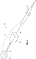
- Fig. 1 is a highly-schematic representation of one embodiment of a system 10 for delivering pulsed RF energy to an ablation catheter 12 during catheter ablation, showing possible communication pathways 14, 16, 18 between primary components in this embodiment.
- This figure depicts a generator 20 operatively connected to a pulse control box 22, which is operatively connected to the ablation catheter 12.
- a dashed line 14 represents temperature feedback from the catheter to the pulse control box 22 of readings from at least one temperature sensor mounted in the tip of the catheter 12.
- the catheter may comprise multiple thermal sensors (for example, thermocouples or thermistors), as described further below.
- the feedback shown in Fig. 1 from the catheter to the pulse control box may be, for example, the highest reading from among all of the individual temperature sensor readings, or it may be, for example, an average of all of the individual readings from all of the temperature sensors.
- Fig. 1 two communication options, represented by double-headed arrow 24 and single-headed arrow 26, are shown for delivering information to the generator 20 or exchanging information between the pulse control box 22 and the generator 20.
- the communication pathway 18 between the generator 20 and the pulse control box 22 could comprise, for example, multiple, separate electrical connection (not separately shown) between the generator 20 and the pulse control box 22.
- One of these communication lines could be, for example, a separate (possibly dedicated) line for communicating to the generator the highest temperature measured by any of a plurality of temperature sensors mounted in the catheter tip. This could be used to trigger a temperature-based shutdown feature in the generator for patient safety.
- the temperature reading or readings from the catheter may be sent to the pulse control box, which may then feed the highest temperature reading to the generator so that the generator can engage its safety features and shut down if the temperature reading appears to be getting undesirably or unsafely high.
- the generator 20 "thinks” it is delivering RF energy to the catheter, but that energy is being delivered instead to the pulse control box 22.
- the pulse control box determines, based upon the temperature feedback that it receives from the catheter, whether to drive the catheter at the power level coming from the generator or, alternatively, to pulse the delivery of RF energy to the catheter tip.
- the generator may be blind to the fact that the pulse control box 22 is determining whether to send power to the catheter tip or to momentarily suspend delivery of energy to the catheter tip as a means of effectively controlling tissue temperature by monitoring and controlling catheter tip temperature.
- Fig. 2 is similar to Fig. 1 , but depicts the components arranged in a slightly different configuration in an alternative embodiment of a system 10' for delivering pulsed RF energy during catheter ablation.
- the pulse control box 22 is again receiving temperature feedback from the catheter 12 along communication pathway 14.
- the pulse control box 22 is "telling" the generator (e.g., along communication pathway 18') to switch “off' and "on” based on the sensed temperature from the catheter 12.
- the generator 20 then delivers pulsed RF energy to the catheter 12 via communication pathway 28.
- this system 10' for delivering pulsed RF energy as in the system 10 depicted in Fig.
- the power can remain at a desired power level (e.g., 50 or 60 Watts) rather than being reduced to an ineffective level when excessive temperature is sensed by the catheter tip.
- a desired power level e.g., 50 or 60 Watts
- the power is delivered in a pulsed manner; and it is the control of the energy pulses, including control of the length of the time gaps between pulses, that is used to control the tip temperature as a surrogate for controlling the tissue temperature.
- the generator 20 may receive temperature feedback via communication pathway 28 and then pass temperature feedback information to the pulse control box 22, which would then control the generator 20 as described above.
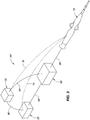
- Fig. 3 is similar to Figs. 1 and 2 , but depicts a system 10" with a dedicated central processing unit (CPU) 30 interfacing with the components 12, 20, 22 also depicted in Figs. 1 and 2 .
- a dedicated CPU is among the components in the system 10" for delivering pulsed RF energy during ablation.
- This figure also shows a number of potential communication pathways between and among the various components, including, for example, a temperature feedback pathway 32 between the catheter and the CPU, the temperature feedback pathway 14 between the catheter and the pulse control box 22, a communication pathway 34 between the generator 20 and the CPU 30, a communication pathway 18" between the generator and the pulse control box, the communication pathway 28 between the generator 20 and the catheter 12, and a communication pathway 36 between the CPU and the pulse control box.
- a temperature feedback pathway 32 between the catheter and the CPU the temperature feedback pathway 14 between the catheter and the pulse control box 22
- a communication pathway 34 between the generator 20 and the CPU 30
- a communication pathway 18" between the generator and the pulse control box
- the communication pathway 28 between the generator 20 and the catheter 12
- a communication pathway 36 between the CPU and the pulse control box
- the generator 20 may directly receive temperature feedback from the catheter 12 along, for example, communication pathway 28.
- the generator 20 could then share that temperature feedback information with the dedicated CPU 30 and/or the pulse control box 22 via one or more of the communication pathways 18", 34, 36.
- Yet another possible alternative to the system 10" depicted in Fig. 3 would be to switch the locations of the pulse control box 22 and the generator 20, similar to the configuration depicted in Fig. 1 , but also include the dedicated CPU 30 depicted in Fig. 3 .
- Fig. 4 schematically depicts a catheter 12 in use in a patient 38 and connected to a generator 40 comprising a pulsed RF control system according to the present disclosure.
- This figure depicts a portion of a human torso of the patient 38, a heart, a representative catheter tip located in the heart, a representative catheter handle, and the RF generator.
- the catheter is assumed to be connected to the RF generator 40.
- the pulse control hardware, software, and/or firmware is built into the generator itself.
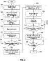
- Fig. 5 is a flowchart depicting one possible control flow, including various optional steps, for delivering pulsed RF energy to an ablation catheter.
- the process commences at block 502.
- the generator is placed in a "power-control" mode.
- the generator power is set to a desired power level for a desired initial time.
- that initial power level is shown as 50 Watts and the initial time is shown as 60 seconds; however, both of these are merely sample values.
- the pulse control may be set to setpoint 1.
- the pulse control box 22 (see, for example, Fig. 1 ) is a PID controller (also known as a proportional-integral-derivative controller or a three-term controller)
- setpoint 1 may relate to the measured process variable (PV). That measured process variable may be the temperature feedback coming from the catheter tip during the ablation cycle.
- a PID controller calculates an error value as the difference between a measured process variable - e.g., measured tip temperature - and a desired setpoint - e.g., a desired tip temperature. The controller then attempts to minimize the error by adjusting the process through use of a manipulated variable (MV) - e.g., the time that a selected power is actively delivered to an ablation tip.
- MV manipulated variable
- the controller calculates a weighted sum of P, I, and D, and then uses that value to adjust the process - here by adjusting the time when RF power is delivered to the ablation tip (e.g., by pulsing the delivery of RF energy to the tip).
- a user is allowed to "tune" the three values, namely the P, I, and D values.
- the controller may be a separate controller as discussed herein and shown in Figs.
- RF power is turned “on” and “off' based on the temperature feedback as it is interpreted and analyzed by the pulse control box.
- the ablation cycle begins.
- the control system monitors the catheter tip temperature. As noted above, this would be the "PV" value in a PID controller. As represented by block 514 and its loop back to block 512, as long as the tip temperature is not close to setpoint 1, the system continues to permit the delivery of full RF power to the ablation tip and continues to monitor catheter tip temperature at block 512. Once the measured tip temperature is approximately at the value of setpoint 1 (e.g., 40 °C in one example), the pulse control box (e.g., the PID controller) would begin to pulse the RF energy being delivered to the catheter tip (see block 516) in an effort to keep the tip temperature approximately at setpoint 1.
- setpoint 1 e.g. 40 °C in one example
- the temperature setting on the pulse control box 22 is changed to setpoint 2, which may be, for example, a higher value than setpoint 1.
- setpoint 2 is 55 °C.
- the full RF power may be delivered to the catheter tip (see block 520).
- the system may stop delivering pulsed RF energy to the ablation tip as the system tries to drive the tip temperature from the setpoint 1 temperature to the setpoint 2 temperature.
- the system monitors the tip temperature.
- decision block 524 the system compares the temperature at the ablation tip to setpoint 2. If the tip temperature is not yet approximately equal to the value of setpoint 2, the system repeatedly returns to block 522 and continues to monitor the tip temperature being reported to the pulse control box. Once the tip temperature is approximately equal to the value of setpoint 2, control transfers from block 524 to block 526 in Fig. 5 .
- Block 526 is similar to block 516 and, at this point, the control system begins again to pulse the delivery of RF energy in an effort to keep the tip temperature approximately at setpoint 2 without overheating the tissue.
- decision block 528 the system next attempts to determine whether the ablation is complete (e.g., a physician may stop calling for the delivery of ablation energy). Once it is determined that the ablation is complete (e.g., when, a physician determines that sufficient RF energy has been delivered to the tissue), control transfers to block 530; and all delivery of RF energy to the ablation tip is stopped.
- the PID controller receives values for setpoint 1 and setpoint 2, which may be entered by a user.
- the PID controller also receives the measured temperature (or multiple measured temperatures if multiple temperature sensors are present) from the catheter tip.
- the controller determines when to permit delivery of full power RF energy or pulsed RF energy to the ablation tip, including, in the latter case, the length of the pulses (i.e., the time periods when RF energy is being delivered to the catheter tip) and the length of the time periods when no RF energy is being delivered to the catheter tip.
- the length of the pulses and the length of the non-pulse time periods may vary continuously.
- the PID controller determines algorithmically when to turn the RF power "on” and “off' as it receives real-time (or near-real-time) tip temperature feedback from the ablation catheter.
- Fig. 6 depicts six representative controller response curves, showing how a measured process variable (which may be the measured tip temperature in the control systems disclosed herein) may approach a setpoint (which may be the desired tip temperature in the control systems disclosed herein), depending on how the controller is configured.
- the controller response curve labeled "Long Integral Action Time" in Fig. 6 may be a desirable controller response as the tip temperature is driven from its starting temperature to the desired ablation temperature.
- the temperature would never exceed the setpoint temperature (e.g., setpoint 1 or setpoint 2 in Fig. 5 ), but would reach the setpoint temperature in a timely and efficient manner.
- Fig. 7 depicts a representative controller response curve and depicts how a measured process variable (PV) at a first setpoint ("initial steady state value of PV”) may be driven to a second setpoint ("final steady state value of PV").
- PV process variable
- This 'dual setpoint' configuration is represented in the full flowchart of Fig. 5 , which is described above. It should be noted, however, that such a dual setpoint control scheme is not required. In other words, an effective controller could drive the catheter tip temperature directly to the setpoint ultimately desired, without driving to a first value (e.g., setpoint 1) and then driving to a second value (e.g., setpoint 2).
- blocks 518-526 are labeled "optional" in Fig. 5 .
- setpoint 1 could be an initial temperature that is somewhere between the starting temperature of the ablation tip and the ultimate desired temperature for the ablation tip. If the system is able to reach the setpoint 1 value effectively and while remaining under control, that would provide the user with confidence that the tip is in contact with the tissue and that the controller is working properly before the tip temperature reaches a potentially dangerously-high temperature.
- setpoint 1 i.e., where control transitions from block 514 to block 516 in Fig. 5
- the user with have confidence that the controller is functioning properly and could then, at block 518 of Fig. 5 , input a higher (ultimately desired) working temperature for creating lesions.
- an ablation tip having a relatively low thermal mass also known as ablation tip having high thermal sensitivity. If the ablation tip has a relatively low thermal mass, it more rapidly heats (i.e., it comes to temperature quickly) and cools (i.e., it does not remain hot for long after power is removed), enabling tighter control of the tip temperature and less "coasting" of the tip temperature past a desired setpoint as well as more rapid reduction in tip temperature when RF power is removed from the tip. In fact, such a tip may cool down at the same rate as the tissue, which would inform the user whether the tip became dislodged during ablation. Remaining Figs.
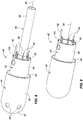
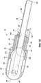
- Fig. 8 is a fragmentary, isometric view of various components comprising an embodiment of a tip 42 at the distal end of an ablation catheter that could be used with the pulsed RF control systems disclosed herein.
- a conductive shell 44 e.g., a platinum shell, a platinum iridium shell, or a gold shell
- the conductive shell 44 (which may weigh, for example, 0.027g) includes a shell distal end portion 48 and a shell proximal end portion 50, which may comprise one or more parts or components.
- the shell 44 includes six irrigation holes 46, two of which are visible in this isometric view.
- FIG. 8 Also visible in Fig. 8 is an optional shank 52 comprising an annular or washer-shaped brim 54 and a cylindrical open crown 56, which together define the top-hat-shaped shank.
- the conductive shell 44 and the shank 52 effectively encase an ablation tip insert 58, the proximal surface 60 of which is partially visible in Fig. 8 .
- An electrical lead wire 62 is shown connected (e.g., by soldering or welding) to the shank 52. Alternatively, the electrical lead wire 62 may be directly connected to the conductive shell 44.
- a number of lead wire pairs 64 for the temperature sensors comprising part of the tip may be seen extending rearwardly or proximally in Fig. 8 .
- FIG. 8 also shows two components of an irrigation tube assembly 66 extending proximally in Fig. 8 (i.e., rightwardly in this figure).
- the conductive shell 44 depicted in the figures includes six irrigation holes 46, more or fewer holes may be used, and the size of the holes may be larger, or smaller, or a mix of larger and smaller holes.
- Fig. 9 is similar to Fig. 8 , but the conductive shell 44' depicted in Fig. 9 does not include any irrigation ports or holes through it (compare element 46 in Fig. 8 ). Thus, this is a non-irrigated catheter tip 42' that could be used in combination with the pulsed RF control systems described herein.
- Most of the discussion below focuses on the irrigated catheter tip embodiment 42 of Fig. 8 , but much of what is said below regarding the embodiment 42 depicted in Fig. 8 applies equally well to the nonirrigated catheter tip embodiment 42' depicted in Fig. 9 , with the exception of the discussion of the irrigation features.
- the irrigation tube assembly 66 (shown in Fig. 8 ) is not necessary in the non-irrigated catheter tip embodiment 42' depicted in Fig. 9 (and, thus, is not shown in Fig. 9 ), the irrigation tube assembly 66 could be present on the non-irrigated catheter tip embodiment.
- the proximal surface 60' of the ablation tip insert of the non-irrigated embodiment 42' may be slightly different from the proximal surface 60 ( Fig. 8 ) of the ablation tip insert 58 (see also Fig. 10 ) of the irrigated embodiment 42 ( Fig. 8 ).
- the proximal surface 60' may not include the main channel 84, which is discussed further below in connection with Fig. 10 .
- the non-irrigated embodiment of Fig. 9 could, however, just as easily use the same ablation tip insert 58 and the irrigation tube assembly 66 shown in the irrigated catheter tip embodiment 42 of Fig. 8 , which would make it possible, for example, to manufacture both irrigated and non-irrigated embodiments on a single assembly line, and would likely result in the two embodiments exhibiting more similar structural integrity during use.
- Fig. 10 which is an exploded, isometric view of the catheter tip 42 depicted in Fig. 8 , is described next, starting with the elements shown in the upper left-hand portion of that figure and working toward the lower right-hand portion of the figure.
- Fig. 10 again depicts the conductive shell 44, but this time exploded away from the other components of the tip shown in Figs. 8 and 10 , thereby revealing additional features and components.
- To the right of the conductive shell in Fig. 10 is an assembly of an ablation tip insert 58 and one temperature sensor 68 (e.g., a thermocouple). As may be seen in Fig.
- the tip insert 58 includes a plurality of lateral irrigation channels 70 that are sized and arranged to align with complementary irrigation holes 46 through the conductive shell 44.
- the diameter of the lateral irrigation channels 70 in the tip insert 58 may be smaller than the complementary holes 46 through the conductive shell 44.
- the tip insert which may be a unitary piece, includes a main body 72 and a stem 74.
- the tip insert 58 can be constructed from, for example, plastic (such as PEEK, which is polyether ether ketone) or thermally-insulative ceramic.
- the main body portion 72 includes a plurality of optional, longitudinally-extending sensor channels or ditches 76.
- a thermal sensor 68 is shown mounted in one of these ditches 76.
- Each of the sensor ditches is separated from the next adjacent sensor ditch by a longitudinally-extending shell seat 78.
- the plurality of shell seats between the sensor ditches are configured to ride against, or very near to, the inner surface of the conductive shell 44.
- the stem 74 of the tip insert 58 defines a plurality of longitudinally-extending wire channels or ditches 80 separated by a plurality of longitudinally-extending shank seats 82.
- the ditches 76, 80 are configured to carry temperature sensor lead wires on their path to the proximal end of the catheter.
- the shank seats 82 are sized and configured to ride against, or very near to, the inner surface of the cylindrical open crown portion 56 of the shank 52.
- the tip insert 58 includes a main channel 84 having a circular cross-section that, as shown in the figures and as described further below, may include more than one inner diameter.
- the irrigation tube assembly comprises, in this embodiment, a central irrigation tube 86 and an optional seating sleeve 88.
- the central irrigation tube 86 has a distal end 90 and a proximal end 92 and may be constructed from a polymer, such as polyimide. This central irrigation tube may extend proximally toward a catheter handle, or may extend proximally all the way to the catheter handle.
- the optional seating sleeve 88 as shown in the embodiment depicted in Fig. 10 , may include a cylindrical portion and a frustoconical boss.
- the seating sleeve may be positioned at a desired longitudinal location along the outer surface of the central irrigation tube 86 and then may be fixed in place (for example, by an adhesive or sonic welding or via some other technique).
- the irrigation tube assembly would then be mounted in the tip insert by, for example, adhesive. If the optional seating sleeve is not included (e.g., to simplify tip construction and manufacturing), the central irrigation tube 86 could be adhered directly to the tip insert 58.
- the optional shank 52 To the right of the irrigation tube assembly in Fig. 10 is the optional shank 52. Details of the shank are described further below in connection with, for example, Fig. 14 . To the right of the shank are five additional temperature sensors 68.
- Fig. 8 six temperature sensors are radially disposed symmetrically about the catheter longitudinal axis 94 (see, for example, Fig. 8 ). Since one of those six thermal sensors is depicted already in position on the tip insert 58 in Fig. 10 , the remaining five temperature sensors are shown in the lower right-hand portion of Fig. 10 , oriented and arranged so as to slip into the remaining five complementary sensor ditches 76 formed in the tip insert.
- Figs. 11-13 are additional views of the conductive shell 44 depicted in, for example, Figs. 8 and 10 .
- the conductive shell may comprise a hemispherical or nearly-hemispherical domed distal end 48 and a cylindrical body 50.
- a 'seam' 96 is shown between the domed distal end 48 and the cylindrical body 50. This may be merely a circumferential transition line between the cylindrical body and the domed distal end of a unitary component; or, alternatively, it may be the location where the cylindrical body is connected to the domed distal end by, for example, welding.
- the wall thickness 98 of the shell is 0,0508 mm (0.002 inches), but alternative wall thicknesses also work.
- the conductive shell could be formed or manufactured by, for example, forging, machining, drawing, spinning, or coining. Also, the conductive shell could be constructed from molded ceramic that has, for example, sputtered platinum on its external surface. In another alternative embodiment, the conductive shell could be constructed from conductive ceramic material.
- Fig. 14 is an enlarged, isometric view of the shank 52 also depicted in, for example, Figs. 8-10 .
- the brim 54 may include a circumferential outward edge 100 that, as described below, may be connected by welding or soldering to a surface (e.g., the inner surface) of the cylindrical body 50 of the conductive shell.
- the shank includes a cylindrical open crown 56 that also defines an inner surface. As described above, the inner surface of the cylindrical open crown is sized and configured to slide over the shank seats 82 defined on the stem of the tip insert 58.
- the cylindrical open crown of the shank also defines a proximal end or edge 102.
- Fig. 15 is an isometric, cross-sectional view of various components of the catheter tip 42 also depicted in Fig. 8 and clearly shows two temperature sensors 68 mounted in their respective temperature sensor ditches 76.
- the sensor ditches may include a wire ramp 104 that allows the thermal sensor lead wires 64 to transition from the sensor ditches 76 (formed in the main body of the tip insert) to the wire ditches 80 (formed in the stem of the tip insert).
- the circumferential outer edge 100 of the brim 54 of the shank 52 is shown riding against the inner surface of the cylindrical body of the conductive shell 50.
- the shank may be welded or soldered to the conductive shell at this interface to ensure good electrical contact between the shank and the shell.
- the tip electrode lead wire 62 may be electrically connected to the cylindrical open crown 56 of the shank 52 in this embodiment, the shank must be conductively connected to the conductive shell 44 in a manner that permits transfer of energy from the tip electrode lead wire 62 to the shank 52 and then to the conductive shell 44.
- the irrigation tube assembly 66 shown in Fig. 15 it is possible to see that the distal end 90 of the central irrigation tube 86 rides against an inner annular ledge 106 formed as part of the tip insert 58. Further, the frustoconical boss defines a distally-facing ledge or lip that rides against the distal end of the stem 74 of the tip insert 58. Thus, the irrigation tube assembly seats against both the proximal surface 60 of the tip insert 58 as well as the inner annular ledge 106 defined along the longitudinal irrigation channel 84 extending through most of the tip insert 58.
- any voids in the assembled tip may be filled with potting material, providing a durable assembled set of components.
- the outer surface of the temperature sensors are mounted so as to at least be in close proximity to, and preferably so as to be in physical contact with, the inner surface of the conductive shell 44.
- "in close proximity to” means, for example, within 0,00508 to 0,0254 mm (0.0002 to 0.0010 inches), particularly if a conductive adhesive or other bonding technique is used to bond the temperature sensors to the inner surface of the shell.
- the distal end portions of the sensor ditches 76 may be shallower than the proximal end portions of the sensor ditches. In this manner, when a temperature sensor 68 is mounted in its respective sensor ditch, the distal most portion of the temperature sensor is "lifted” toward and possibly against the inner surface of the cylindrical body of the conductive shell 44. This helps to establish good thermal conductivity between the conductive shell and the thermal sensor or sensors mounted inside of the shell.
- Fig. 16 is similar to Fig. 15 , but is a cross-sectional view taken at a slightly different angular orientation from that shown in Fig. 15 , to thereby reveal two of the lateral irrigation channels 70 configured to deliver irrigant 108 outside of the tip 42. Since the conductive shell is very thin in these embodiments, and since the tip insert is constructed from an insulative material, the irrigant, when used, has very little ability or opportunity to influence the temperature of the conductive shell 44. As shown to good advantage in Fig. 16 , the irrigant exiting the lateral irrigation channels touches the inner edges of the holes 46 through the conductive shell before exiting to the surrounding blood. This may be contrasted to what is shown in Fig.
- Fig. 18 depicts a prior art catheter tip 42".
- Fig. 18 depicts a solid platinum (or platinum iridium) tip 110 with a polymer irrigation tube 86 mounted in it.
- the irrigant 108 flows through and directly contacts a portion of the platinum tip before reaching the lateral irrigation channels 70' and then exiting the tip.
- the cool irrigant rides directly against the platinum comprising the conductive tip.
- the irrigant has a much greater opportunity to influence the temperature of the tip than does the irrigant in the embodiment depicted in, for example, Fig. 16 .
- the temperature of the conductive shell in the immediate vicinity of the tissue-tip interface heats up quickly, and the sensor 68 closest to that portion of the conductive shell rapidly senses and reports a temperature rise in the immediate vicinity of the tissue-tip interface. It is not necessary for the entire tip to heat up before the sensor can report a temperature rise in the tissue, the blood flowing around the entire tip thus has less of an opportunity to distort the sensed tip temperature, and fewer temperature averaging issues come into play.
- Fig. 17 is an enlarged, fragmentary, cross-sectional view showing one possible interconnection between the cylindrical body 50 of the conductive shell 44, the shank 52, and the RF lead wire 62.
- a proximal edge 112 of the cylindrical body 50 of the conductive shell is bent around the circumferential outward edge 100 of the shank brim 54.
- the shank brim and the shell body are then connected by welding or soldering, for example.
- energy coming from the RF lead wire 62 can be delivered to the shank crown 56, conducted to the shank brim 54, and then delivered to the cylindrical body 50 of the conductive shell.
- Fig. 19 is similar to Figs. 15 and 16 , and depicts another fragmentary, isometric, cross-sectional view, but this time taken from an angular orientation that clearly shows a distal-most thermal sensor 114.
- this figure clearly depicts an arc-shaped channel 116 extension extending from one of the sensor ditches 76.
- the distal-most thermal sensor i.e., a seventh thermal sensor in this embodiment
- This distal-most thermal sensor is shown having a spherical shape in Fig. 19 and being placed ahead of (i.e., distally of) one of the radially-disposed thermal sensors 68.
- Fig. 20 is an isometric view of components of the tip also depicted in, for example, Figs. 8 , 10 , 15 , 16 , and 19 .
- all six of the radially-disposed thermal sensors 68 are in place in their respective sensor ditches 76.
- the seventh, distal-most thermal sensor may also be in place, but is not shown in this particular figure.
- This figure also clearly shows the frustoconical boss comprising part of the optional seating sleeve 88 with its distally-facing surface or tip resting against the proximally-facing surface 60 of the tip insert 58.
- Fig. 21 is similar to Fig. 20 , but shows components of the catheter tip from a different view, wherein the distal-most thermal sensor 114 (i.e., the seventh thermal sensor in this embodiment) is visible, and this view also includes the shank 52, which is not present in Fig. 20 .
- the shank is in place over the stem of the tip insert, which helps clarify the benefit of the wire ramps 104 connecting the sensor ditches 76 to the wire ditches, both of which are formed in the tip insert.
- Fig. 22 is an isometric view of just the thermally-insulative ablation tip insert 58 also depicted in Fig. 21 , but without any other tip components.
- All of the ablation tip inserts described herein are preferably constructed from thermally-insulative material. They could be constructed from, for example, ULTEM.
- the tip insert includes six laterally-extending irrigation channels 70, each of which has a longitudinal axis arranged substantially perpendicular to the longitudinal axis of the tube channel that is itself arranged substantially parallel to the catheter longitudinal axis 94.
- the laterally-extending irrigation channels connect a distal end of the tube channel 84 to an outer surface of the tip insert.
- the laterally-extending irrigation channels could be arranged at a different angle (i.e., different from 90°) relative to the tube channel longitudinal axis.
- more or fewer than six laterally-extending irrigation channels may be present in the tip insert.
- the outer surface of the tip insert may define a plurality of sensor ditches 76, and these ditches may be separated by a plurality of shell seats 78. These sensor ditches may be, for example, 0,254 mm (0.010 inches) deep.
- the shell seats, as described above, may be configured to ride against, or very near to, the inner surface of the conductive shell. A few of the sensor wire ramps are also clearly visible in Fig. 22 .
- the stem 74 of the tip insert may define a plurality of wire ditches 80 separated by a plurality of shank seats 82 as shown in Fig.22 .
- Fig. 23 depicts the tip insert 58 of Fig. 22 in a slightly different orientation, revealing the arc-shaped channel 116 (or sensor ditch extension) that extends toward the distal-most end of the catheter tip to position the distal-most thermal sensor 114 (see, for example, Fig. 21 ) at that location.
- this arc-shaped channel extension need not be present. It has been determined, however, that a number of advantages may be realized by positioning a thermal sensor as far distally on the catheter tip as possible. For example, in view of the rapid heat dissipation experienced by these catheter tips, it can be extremely helpful to sense temperature at this distal location since it may be in the best location for most accurately determining the temperature of the surrounding tissue during certain procedures.
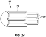
- Fig. 24 depicts an alternative thermally-insulative ablation tip insert 58'.
- This tip insert could be used in a non-irrigated embodiment of the catheter tip 42', such as the embodiment depicted in Fig. 9 .
- the control systems for delivering pulsed RF to ablation catheters described herein may completely eliminate the need for the use of irrigation.
- Fig. 24 depicts one possible configuration for a tip insert for use in a non-irrigated ablation catheter. This embodiment of the tip insert still includes sensor ditches 76 and sensor wire ditches 80 as described above.
- the thermally-insulative ablation tip insert there may be more or fewer sensor ditches 76.
- the sensor ditches may facilitate placement of the sensors 68 on the insert (e.g., during catheter assembly), the outer surface of the main body of the tip insert may be smooth (or at least ditchless). In such an embodiment, the sensors may be aligned on the smooth outer surface of the tip insert (and, possibly, held in place by, for example, adhesive).
- the gaps or voids between the inner surface of the conductive shell and the outer surface of the tip insert may be filled with material (e.g., potting material or adhesive).
- material e.g., potting material or adhesive.
- the sensors may be put in place before or after the conductive shell is placed over the tip insert. For instance, the sensors may be mounted on (e.g., adhered to) the smooth outer surface of the tip insert forming a tip-insert-sensor subassembly.
- the conductive shell may be placed over that tip-insert-sensor subassembly before the remaining voids between the tip-insert-sensor subassembly and the conductive shell are filled.
- the conductive shell may be held in place over the tip insert while one or more sensors are slid into the gap between the outer surface of the tip insert and the inner surface of the conductive shell. Subsequently, the voids could again be filled.
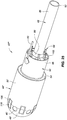
- Fig. 25 is most similar to Fig. 8 , but depicts one form of an alternative embodiment of a catheter tip 42'" comprising one or more isolated temperature-sensing islands 118 which, in this embodiment, reside partially on the doomed distal end 48' of the conductive shell 44" and partially on the cylindrical body 50' of the conductive shell 44".
- Each of these temperature-sensing islands 118 is outlined or circumscribed by a strip of insulative material 120 placed to reduce or eliminate any potential influence from irrigant flowing through the nearby holes 46' in the conductive shell.
- a single-layer conductive shell 44 (see, e.g., Figs. 10-13 and 15 ) constructed from a thin layer of gold, for example, may perform in an magnetic resonance (MR) environment without causing undesirable or unmanageable MR artifacts
- a conductive shell comprising an outer layer of a paramagnetic material such as platinum or platinum iridium, for example, may benefit from a multilayer construction as discussed below.
- Fig. 26 is most similar to Fig. 12 , but depicts a multilayer conductive shell 44'".
- a multilayer conductive shell may have just a multilayer cylindrical body portion, just a multilayer domed distal end portion, or both a multilayer domed distal end portion and a multilayer cylindrical body.
- both the domed distal end portion 48'" and the cylindrical body 50'" have a multilayer construction.
- the domed distal end portion 48'" comprises an inner layer 122 and an outer layer 124
- the cylindrical body 50'" similarly comprises an inner layer 126 and an outer layer 128.
- the domed distal end portion and the cylindrical body must both be constructed with the same number of layers or with the same thickness of layers.
- the walls of the conductive shell 44'" may, for example, be of a total thickness that is the same as, or nearly the same as, the thickness 98 (see Fig. 12 ) of the single-layer conductive shell 44 described above.
- the conductive shell could be formed or manufactured per, for example, the techniques already described herein.
- Figs. 27A, 27B, and 27C schematically depict various materials or substances in a magnetic field (e.g., in an MR environment).
- Fig. 27A schematically depicts magnetic flux lines reacting to a diamagnetic substance (the lines of force tend to avoid the substance when placed in a magnetic field)
- Fig. 27B schematically depicts magnetic flux lines reacting to a paramagnetic substance (the lines of force prefer to pass through the substance rather than air)
- Fig. 27C schematically depicts magnetic flux lines reacting to a ferromagnetic substance (the lines of force tend to crowd into the substance).
- Platinum iridium (a paramagnetic material) is commonly used for constructing catheter tips.
- a thin conductive shell e.g., conductive shell 44 depicted in Fig. 12
- a thin conductive shell constructed entirely from platinum or platinum iridium (or some other paramagnetic material) may induce MR artifacts.
- a more MR compatible catheter tip may comprise, for example, a single layer conductive shell 44 constructed entirely from a diamagnetic material (e.g., a thin gold conductive shell) or a multilayer conductive shell 44"'.
- the conductive shell 44'" comprises a shell distal end portion (shown as domed distal end 48'" in Fig. 26 ) and a shell proximal end portion (shown as cylindrical body 50'" in Fig. 26 ).
- the conductive shell 44'" may comprise a platinum iridium outer layer (or skin) 124, 128 and an inner layer (or liner or core) 122, 126 constructed from a diamagnetic material (e.g., gold or copper).
- a diamagnetic material e.g., gold or copper
- the paramagnetic outer layer 124, 128 and the diamagnetic inner layer 122, 126 ' cooperate' in a manner that minimizes or mitigates against the generation of undesirable MR artifacts.
- the multilayer conductive shell 44'" of the MR compatible catheter tip may have an outer layer constructed from a diamagnetic material (such as bismuth or gold) and an inner layer constructed from a paramagnetic material (such as platinum or platinum iridium).
- a diamagnetic material such as bismuth or gold
- a paramagnetic material such as platinum or platinum iridium
- a multilayer conductive shell may comprise more than two layers.
- the conductive shell may comprise three layers, including a very thin outer layer of a paramagnetic material, a somewhat thicker or much thicker intermediate layer of a diamagnetic material, and an oversized internal layer of a non-precious metal (or plastic or other material) sized to ensure that the finished geometry of the overall ablation tip is of a desired size for effective tissue ablation.
- one example multilayer shell configuration could comprise a platinum outer layer (or skin) and an inner layer (or liner or core) of gold or silver with a thickness ratio (e.g., platinum-to-gold thickness ratio) of at least 1/10 (i.e., the platinum layer being one-tenth as thick as the gold layer).
- a thickness ratio e.g., platinum-to-gold thickness ratio
- a multilayer conductive shell configuration 44'" could comprise a platinum outer layer and a bismuth inner layer with a thickness ratio (e.g., platinum-to-bismuth thickness ratio) of at least 1/2 (i.e., the platinum outer layer being one-half as think as the bismuth inner layer) since bismuth has a permeability that is about one-half the permeability of platinum.
- the layers may also be constructed from alloys, which may be used, for example, when a pure element material might otherwise be disqualified from use in the construction of a catheter tip.
- Fig. 28 is most similar to Fig. 20 , but depicts an embodiment having both distal temperature or thermal sensors 68 and proximal temperature or thermal sensors 68' mounted on a tip insert. As depicted in Fig. 28 , a plurality of temperature sensors 68' may be deployed around or near the proximal end of the tip 42. These temperature sensors 68' could be mounted, for example, on the ablation tip insert as already described above. Although Fig. 28 depicts an ablation tip insert 58 for an irrigated tip 42, the proximal temperature sensors 68' may also be used in nonirrigated embodiments such as the tip 42' depicted in Fig. 9 .
- the proximal thermal sensors 68' may be deployed, for example, in an angularly-spaced configuration similar to the configuration of the six radially-disposed distal temperature sensors 68 shown in, for example, Figs. 15 , 19 , 20 , and 21 (but located near the proximal end of the main body 72 of the ablation tip insert 58 rather than its distal end).
- the temperature sensor configuration depicted in Fig. 28 would provide a higher-resolution 'picture' of the thermal profile of the tip and, therefore, a better understanding of tissue temperature near the catheter tip during ablation. This is particularly beneficial when such a tip construction is used with the pulsed RF control systems disclosed herein.
- catheter tips having a variety of thermometry configurations could be deployed successfully with the pulsed RF control systems described herein.
- the representative catheter tips described herein include six or twelve radially-disposed temperature sensors and one distal temperature sensor placed close to the distal end of the catheter tip, the invention is not limited to such seven-sensor and thirteen-sensor configurations.
- catheters comprising various segmented tip designs may work to good advantage with the control systems described above.
- Some such tip configurations are disclosed in United States patent application no. 61/896,304, filed 28 October 2013 , and in related international patent application no. PCT/US2014/062562, filed 28 October 2014 and published 07 May 2015 in English as international publication no. WO 2015/065966 A2 .
- control systems described herein may use a "rolling thermocouple,” which would, for example, measure the temperature output from each of a plurality of thermocouples every 20 msec (for example) and report the highest of these temperatures to the pulse control box and, potentially, directly to the generator (at least for safety shutdown reasons).
- the controller is always working with the most accurate representation of the actual tissue temperature.
- any temperature sensors facing away from the tissue during use of the catheter in an ablation procedure would cool rapidly and their readings could be ignored or discounted, whereas the temperature sensor or sensors closest to the portion of the catheter tip that is in contact with tissue would heat rapidly and would, therefore, provide a temperature reading that is closest to the actual temperature of the tissue being ablated.
- the system is able to rapidly adjust for the widely varying readings being received from the thermal sensors as the catheter tip is rotated or pushed into tissue during actual use.
Landscapes
- Health & Medical Sciences (AREA)
- Life Sciences & Earth Sciences (AREA)
- Surgery (AREA)
- Engineering & Computer Science (AREA)
- Plasma & Fusion (AREA)
- General Health & Medical Sciences (AREA)
- Otolaryngology (AREA)
- Physics & Mathematics (AREA)
- Veterinary Medicine (AREA)
- Biomedical Technology (AREA)
- Heart & Thoracic Surgery (AREA)
- Medical Informatics (AREA)
- Molecular Biology (AREA)
- Animal Behavior & Ethology (AREA)
- Nuclear Medicine, Radiotherapy & Molecular Imaging (AREA)
- Public Health (AREA)
- Cardiology (AREA)
- Surgical Instruments (AREA)
- Media Introduction/Drainage Providing Device (AREA)
Claims (13)
- System zur Steuerung der Energiezufuhr an einen Ablationskatheter während eines Ablationsverfahrens, miteinem Ablationsgenerator (20), der in einem Leistungssteuerungsmodus betrieben werden kann,einer Eingabevorrichtung zum Eingeben einer gewünschten Ablationsleistungshöhe,einer Eingabevorrichtung zum Eingeben eines gewünschten Temperatursollwerts, undeiner Impulssteuerungsbox (22), die dazu angepasst ist, während eines Katheterablationsverfahrens eine Temperaturrückkoppelung von einem Ablationskatheter (12) zu empfangen, dadurch gekennzeichnet, dassdie Impulssteuerbox dazu konfiguriert ist, dass sie eine Ablationsenergie dem Ablationskatheter (12) mit der gewünschten Ablationsleistungshöhe während des Katheterablationsverfahrens impulsförmig zuführt, während sie die empfangene Temperaturrückkoppelung an oder nahe dem gewünschten Temperatursollwert hält.
- System nach Anspruch 1, bei demder Generator (20) dazu konfiguriert ist, eine RF-Energie zu erzeugen,die Impulssteuerbox (22) operativ mit dem Generator (20) verbunden ist und dazu konfiguriert ist, die Zufuhr von RF-Energie zu steuern, und dazu angepasst ist, die RF-Energie in einer pulsierenden Weise zuzuführen, undder Ablationskatheter (12) zumindest einen Temperatursensor aufweist, der in einer Spitze des Ablationskatheters (12) montiert ist, und bei dem der Ablationskatheter (12) operativ mit der Impulssteuerungsbox (22) verbunden ist und dazu angepasst ist, die Spitzentemperatur an die Impulssteuerungsbox (22) zu übermitteln.
- System nach Anspruch 2, bei dem der zumindest eine Temperatursensor ausgewählt ist aus der Gruppe, die aus Thermoelementen und Thermistoren besteht.
- System nach Anspruch 2 oder 3, bei dem der zumindest eine Temperatursensor eine Mehrzahl von Temperatursensoren aufweist, und bei dem die Spitzentemperaturinformation, die der Impulssteuerungsbox (22) zugeführt wird, eine höchste Temperatur aufweist, die durch einen von der Mehrzahl von Temperatursensoren erfasst wird.
- System nach Anspruch 4, das ferner eine dezidierte Kommunikationsleitung zum Übermitteln der höchsten Temperatur, die von einem der Mehrzahl von Temperatursensoren erfasst wird, an den Generator (20), bei dem der Generator (20) dazu konfiguriert ist, eine Leistung zu reduzieren oder abzuschalten, wenn immer die höchste Temperatur einen vorbestimmten Schwellenwert überschreitet.
- System nach Anspruch 2 oder 3, bei dem der zumindest eine Temperatursensor eine Mehrzahl von Temperatursensoren aufweist, und bei dem die Spitzentemperaturinformation, die der Impulssteuerungsbox (22) zugeführt wird, einen Durchschnittswert von allen individuellen Temperaturen aufweist, die von allen Temperatursensoren, die die Mehrzahl von Temperatursensoren aufweist, erfasst werden.
- System nach Anspruch 2 oder 3, bei dem der zumindest eine Temperatursensor eine Mehrzahl von Temperatursensoren aufweist, bei dem der Generator (20) dazu konfiguriert ist, dass er eine RF-Energie der Impulssteuerungsbox (22) zuführt, und bei dem die Impulssteuerungsbox (22) dazu konfiguriert ist, zu bestimmen, ob die RF-Energie, die von dem Generator (20) empfangen wird, zu der Spitze des Ablationskatheters (12) passiert, basierend auf zumindest den Temperaturen, die durch die Mehrzahl von Temperatursensoren erfasst werden.
- System nach Anspruch 2 oder 3, bei dem der zumindest eine Temperatursensor eine Mehrzahl von Temperatursensoren aufweist, bei dem der Generator (20) dazu konfiguriert ist, RF-Energie direkt dem Ablationskatheter zuzuführen, und bei dem die Impulssteuerungsbox (22) dazu konfiguriert ist, basierend auf zumindest den Temperaturen, die durch die Mehrzahl von Temperatursensoren erfasst werden, zu bestimmen, ob dem Generator (20) anzuweisen ist, eine RF-Energie der Spitze des Ablationskatheters (12) zuzuführen.
- System nach Anspruch 7 oder 8, bei dem der Generator dazu konfiguriert ist, eine RF-Leistung zuzuführen, ohne dass die Leistung titriert wird, in Reaktion auf ansteigende Temperaturen, die durch die Mehrzahl von Temperatursensoren erfasst werden.
- System nach einem der Ansprüche 1 bis 9, bei dem der Generator (20) dazu konfiguriert ist, pulsierende RF-Energie dem Ablationskatheter (12) zuzuführen, bei dem der Generator dazu konfiguriert ist, die Spitzentemperatur zu steuern, indem er (i) eine erste Zeitdauer zwischen aufeinanderfolgenden Impulsen der RF-Leistung und (ii) eine zweite Zeitdauer steuert, während die RF-Energie der Spitze des Ablationskatheters (12) zugeführt wird.
- System nach einem der Ansprüche 1 bis 10, das ferne eine CPU aufweist, die operativ mit zumindest einem von dem Generator (20), der Impulssteuerungsbox (22) und dem Ablationskatheter (12) verbunden ist.
- System nach einem der Ansprüche 1 bis 11, bei dem die Impulssteuerungsbox (22) ausgewählt ist aus der Gruppe, die aus einem PID-Regler, einer Mikrosteuerung und einer programmierbaren Logiksteuerung besteht.
- System nach einem der Ansprüche 1 bis 12, bei dem die Impulssteuerungsbox (22) einen integralen Teil des Generators (20) aufweist.
Priority Applications (1)
| Application Number | Priority Date | Filing Date | Title |
|---|---|---|---|
| EP20165976.0A EP3701899B1 (de) | 2015-03-31 | 2016-03-31 | Vorrichtungen zur abgabe gepulster rf-energie bei der katheterablation |
Applications Claiming Priority (3)
| Application Number | Priority Date | Filing Date | Title |
|---|---|---|---|
| US201562141066P | 2015-03-31 | 2015-03-31 | |
| US201562198114P | 2015-07-28 | 2015-07-28 | |
| PCT/US2016/025435 WO2016161211A1 (en) | 2015-03-31 | 2016-03-31 | Methods and devices for delivering pulsed rf energy during catheter ablation |
Related Child Applications (2)
| Application Number | Title | Priority Date | Filing Date |
|---|---|---|---|
| EP20165976.0A Division-Into EP3701899B1 (de) | 2015-03-31 | 2016-03-31 | Vorrichtungen zur abgabe gepulster rf-energie bei der katheterablation |
| EP20165976.0A Division EP3701899B1 (de) | 2015-03-31 | 2016-03-31 | Vorrichtungen zur abgabe gepulster rf-energie bei der katheterablation |
Publications (2)
| Publication Number | Publication Date |
|---|---|
| EP3209236A1 EP3209236A1 (de) | 2017-08-30 |
| EP3209236B1 true EP3209236B1 (de) | 2020-06-10 |
Family
ID=55750497
Family Applications (5)
| Application Number | Title | Priority Date | Filing Date |
|---|---|---|---|
| EP16716145.4A Active EP3209236B1 (de) | 2015-03-31 | 2016-03-31 | Vorrichtung zur abgabe gepulster rf-energie bei der katheterablation |
| EP16716388.0A Active EP3256065B1 (de) | 2015-03-31 | 2016-03-31 | Vorrichtungen zur abgabe gepulster rf-energie bei der katheterablation |
| EP24172408.7A Pending EP4382062A3 (de) | 2015-03-31 | 2016-03-31 | Verfahren und vorrichtungen zur abgabe gepulster hf-energie während der katheterablation |
| EP20199680.8A Active EP3777745B1 (de) | 2015-03-31 | 2016-03-31 | Vorrichtung zur abgabe gepulster hf-energie während der katheterablation |
| EP20165976.0A Active EP3701899B1 (de) | 2015-03-31 | 2016-03-31 | Vorrichtungen zur abgabe gepulster rf-energie bei der katheterablation |
Family Applications After (4)
| Application Number | Title | Priority Date | Filing Date |
|---|---|---|---|
| EP16716388.0A Active EP3256065B1 (de) | 2015-03-31 | 2016-03-31 | Vorrichtungen zur abgabe gepulster rf-energie bei der katheterablation |
| EP24172408.7A Pending EP4382062A3 (de) | 2015-03-31 | 2016-03-31 | Verfahren und vorrichtungen zur abgabe gepulster hf-energie während der katheterablation |
| EP20199680.8A Active EP3777745B1 (de) | 2015-03-31 | 2016-03-31 | Vorrichtung zur abgabe gepulster hf-energie während der katheterablation |
| EP20165976.0A Active EP3701899B1 (de) | 2015-03-31 | 2016-03-31 | Vorrichtungen zur abgabe gepulster rf-energie bei der katheterablation |
Country Status (5)
| Country | Link |
|---|---|
| US (2) | US11350986B2 (de) |
| EP (5) | EP3209236B1 (de) |
| JP (2) | JP6560762B2 (de) |
| CN (2) | CN107205773A (de) |
| WO (2) | WO2016161211A1 (de) |
Families Citing this family (131)
| Publication number | Priority date | Publication date | Assignee | Title |
|---|---|---|---|---|
| US11871901B2 (en) | 2012-05-20 | 2024-01-16 | Cilag Gmbh International | Method for situational awareness for surgical network or surgical network connected device capable of adjusting function based on a sensed situation or usage |
| US11504192B2 (en) | 2014-10-30 | 2022-11-22 | Cilag Gmbh International | Method of hub communication with surgical instrument systems |
| WO2016161211A1 (en) | 2015-03-31 | 2016-10-06 | St. Jude Medical, Cardiology Division, Inc. | Methods and devices for delivering pulsed rf energy during catheter ablation |
| US10869719B2 (en) | 2016-05-02 | 2020-12-22 | Affera, Inc. | Pulsed radiofrequency ablation |
| CN109788983B (zh) | 2016-10-04 | 2022-04-19 | 圣犹达医疗用品心脏病学部门有限公司 | 具有柔性电子电路的消融导管 |
| US20180092689A1 (en) * | 2016-10-04 | 2018-04-05 | St. Jude Medical, Cardiology Division, Inc. | Methods and devices for estimating tip-tissue coupling of an ablation catheter tip |
| WO2018067248A1 (en) | 2016-10-04 | 2018-04-12 | St. Jude Medical, Cardiology Division, Inc. | Ablation catheter tip |
| US11103304B2 (en) * | 2017-06-13 | 2021-08-31 | Biosense Webster (Israel) Ltd. | Catheter with composite insert support member |
| US20210022803A1 (en) * | 2017-08-17 | 2021-01-28 | St. Jude Medical, Cardiology Division, Inc. | Temperature sensor and three-dimensional electrode |
| US11911045B2 (en) | 2017-10-30 | 2024-02-27 | Cllag GmbH International | Method for operating a powered articulating multi-clip applier |
| US11406390B2 (en) | 2017-10-30 | 2022-08-09 | Cilag Gmbh International | Clip applier comprising interchangeable clip reloads |
| US11564756B2 (en) | 2017-10-30 | 2023-01-31 | Cilag Gmbh International | Method of hub communication with surgical instrument systems |
| US11291510B2 (en) | 2017-10-30 | 2022-04-05 | Cilag Gmbh International | Method of hub communication with surgical instrument systems |
| US11801098B2 (en) | 2017-10-30 | 2023-10-31 | Cilag Gmbh International | Method of hub communication with surgical instrument systems |
| US11317919B2 (en) | 2017-10-30 | 2022-05-03 | Cilag Gmbh International | Clip applier comprising a clip crimping system |
| US11311342B2 (en) | 2017-10-30 | 2022-04-26 | Cilag Gmbh International | Method for communicating with surgical instrument systems |
| US11793537B2 (en) | 2017-10-30 | 2023-10-24 | Cilag Gmbh International | Surgical instrument comprising an adaptive electrical system |
| US11510741B2 (en) | 2017-10-30 | 2022-11-29 | Cilag Gmbh International | Method for producing a surgical instrument comprising a smart electrical system |
| US11166772B2 (en) | 2017-12-28 | 2021-11-09 | Cilag Gmbh International | Surgical hub coordination of control and communication of operating room devices |
| US11571234B2 (en) | 2017-12-28 | 2023-02-07 | Cilag Gmbh International | Temperature control of ultrasonic end effector and control system therefor |
| US11540855B2 (en) | 2017-12-28 | 2023-01-03 | Cilag Gmbh International | Controlling activation of an ultrasonic surgical instrument according to the presence of tissue |
| US11857152B2 (en) | 2017-12-28 | 2024-01-02 | Cilag Gmbh International | Surgical hub spatial awareness to determine devices in operating theater |
| US11202570B2 (en) | 2017-12-28 | 2021-12-21 | Cilag Gmbh International | Communication hub and storage device for storing parameters and status of a surgical device to be shared with cloud based analytics systems |
| US11266468B2 (en) | 2017-12-28 | 2022-03-08 | Cilag Gmbh International | Cooperative utilization of data derived from secondary sources by intelligent surgical hubs |
| US11076921B2 (en) | 2017-12-28 | 2021-08-03 | Cilag Gmbh International | Adaptive control program updates for surgical hubs |
| US11432885B2 (en) | 2017-12-28 | 2022-09-06 | Cilag Gmbh International | Sensing arrangements for robot-assisted surgical platforms |
| US11559307B2 (en) | 2017-12-28 | 2023-01-24 | Cilag Gmbh International | Method of robotic hub communication, detection, and control |
| US11659023B2 (en) | 2017-12-28 | 2023-05-23 | Cilag Gmbh International | Method of hub communication |
| US11529187B2 (en) | 2017-12-28 | 2022-12-20 | Cilag Gmbh International | Surgical evacuation sensor arrangements |
| US11589888B2 (en) | 2017-12-28 | 2023-02-28 | Cilag Gmbh International | Method for controlling smart energy devices |
| US11903601B2 (en) | 2017-12-28 | 2024-02-20 | Cilag Gmbh International | Surgical instrument comprising a plurality of drive systems |
| US11559308B2 (en) | 2017-12-28 | 2023-01-24 | Cilag Gmbh International | Method for smart energy device infrastructure |
| US11424027B2 (en) | 2017-12-28 | 2022-08-23 | Cilag Gmbh International | Method for operating surgical instrument systems |
| US20190206569A1 (en) | 2017-12-28 | 2019-07-04 | Ethicon Llc | Method of cloud based data analytics for use with the hub |
| US11278281B2 (en) | 2017-12-28 | 2022-03-22 | Cilag Gmbh International | Interactive surgical system |
| US11896322B2 (en) | 2017-12-28 | 2024-02-13 | Cilag Gmbh International | Sensing the patient position and contact utilizing the mono-polar return pad electrode to provide situational awareness to the hub |
| US11744604B2 (en) | 2017-12-28 | 2023-09-05 | Cilag Gmbh International | Surgical instrument with a hardware-only control circuit |
| US11234756B2 (en) | 2017-12-28 | 2022-02-01 | Cilag Gmbh International | Powered surgical tool with predefined adjustable control algorithm for controlling end effector parameter |
| US11818052B2 (en) | 2017-12-28 | 2023-11-14 | Cilag Gmbh International | Surgical network determination of prioritization of communication, interaction, or processing based on system or device needs |
| US11253315B2 (en) | 2017-12-28 | 2022-02-22 | Cilag Gmbh International | Increasing radio frequency to create pad-less monopolar loop |
| US11389164B2 (en) | 2017-12-28 | 2022-07-19 | Cilag Gmbh International | Method of using reinforced flexible circuits with multiple sensors to optimize performance of radio frequency devices |
| US11419667B2 (en) | 2017-12-28 | 2022-08-23 | Cilag Gmbh International | Ultrasonic energy device which varies pressure applied by clamp arm to provide threshold control pressure at a cut progression location |
| US11419630B2 (en) | 2017-12-28 | 2022-08-23 | Cilag Gmbh International | Surgical system distributed processing |
| US11832899B2 (en) | 2017-12-28 | 2023-12-05 | Cilag Gmbh International | Surgical systems with autonomously adjustable control programs |
| US20190201146A1 (en) | 2017-12-28 | 2019-07-04 | Ethicon Llc | Safety systems for smart powered surgical stapling |
| US11771487B2 (en) | 2017-12-28 | 2023-10-03 | Cilag Gmbh International | Mechanisms for controlling different electromechanical systems of an electrosurgical instrument |
| US11179175B2 (en) | 2017-12-28 | 2021-11-23 | Cilag Gmbh International | Controlling an ultrasonic surgical instrument according to tissue location |
| US11291495B2 (en) | 2017-12-28 | 2022-04-05 | Cilag Gmbh International | Interruption of energy due to inadvertent capacitive coupling |
| US11602393B2 (en) | 2017-12-28 | 2023-03-14 | Cilag Gmbh International | Surgical evacuation sensing and generator control |
| US11896443B2 (en) | 2017-12-28 | 2024-02-13 | Cilag Gmbh International | Control of a surgical system through a surgical barrier |
| US11464535B2 (en) | 2017-12-28 | 2022-10-11 | Cilag Gmbh International | Detection of end effector emersion in liquid |
| US11109866B2 (en) | 2017-12-28 | 2021-09-07 | Cilag Gmbh International | Method for circular stapler control algorithm adjustment based on situational awareness |
| US11998193B2 (en) | 2017-12-28 | 2024-06-04 | Cilag Gmbh International | Method for usage of the shroud as an aspect of sensing or controlling a powered surgical device, and a control algorithm to adjust its default operation |
| US11612444B2 (en) | 2017-12-28 | 2023-03-28 | Cilag Gmbh International | Adjustment of a surgical device function based on situational awareness |
| US11284936B2 (en) | 2017-12-28 | 2022-03-29 | Cilag Gmbh International | Surgical instrument having a flexible electrode |
| US11317937B2 (en) | 2018-03-08 | 2022-05-03 | Cilag Gmbh International | Determining the state of an ultrasonic end effector |
| US11786251B2 (en) | 2017-12-28 | 2023-10-17 | Cilag Gmbh International | Method for adaptive control schemes for surgical network control and interaction |
| US11013563B2 (en) | 2017-12-28 | 2021-05-25 | Ethicon Llc | Drive arrangements for robot-assisted surgical platforms |
| US12096916B2 (en) | 2017-12-28 | 2024-09-24 | Cilag Gmbh International | Method of sensing particulate from smoke evacuated from a patient, adjusting the pump speed based on the sensed information, and communicating the functional parameters of the system to the hub |
| US10758310B2 (en) | 2017-12-28 | 2020-09-01 | Ethicon Llc | Wireless pairing of a surgical device with another device within a sterile surgical field based on the usage and situational awareness of devices |
| US11969142B2 (en) | 2017-12-28 | 2024-04-30 | Cilag Gmbh International | Method of compressing tissue within a stapling device and simultaneously displaying the location of the tissue within the jaws |
| US11364075B2 (en) | 2017-12-28 | 2022-06-21 | Cilag Gmbh International | Radio frequency energy device for delivering combined electrical signals |
| US11464559B2 (en) | 2017-12-28 | 2022-10-11 | Cilag Gmbh International | Estimating state of ultrasonic end effector and control system therefor |
| US11304745B2 (en) | 2017-12-28 | 2022-04-19 | Cilag Gmbh International | Surgical evacuation sensing and display |
| US11633237B2 (en) | 2017-12-28 | 2023-04-25 | Cilag Gmbh International | Usage and technique analysis of surgeon / staff performance against a baseline to optimize device utilization and performance for both current and future procedures |
| US10892995B2 (en) | 2017-12-28 | 2021-01-12 | Ethicon Llc | Surgical network determination of prioritization of communication, interaction, or processing based on system or device needs |
| US11937769B2 (en) | 2017-12-28 | 2024-03-26 | Cilag Gmbh International | Method of hub communication, processing, storage and display |
| US11304720B2 (en) | 2017-12-28 | 2022-04-19 | Cilag Gmbh International | Activation of energy devices |
| US11969216B2 (en) | 2017-12-28 | 2024-04-30 | Cilag Gmbh International | Surgical network recommendations from real time analysis of procedure variables against a baseline highlighting differences from the optimal solution |
| US12062442B2 (en) | 2017-12-28 | 2024-08-13 | Cilag Gmbh International | Method for operating surgical instrument systems |
| US11257589B2 (en) | 2017-12-28 | 2022-02-22 | Cilag Gmbh International | Real-time analysis of comprehensive cost of all instrumentation used in surgery utilizing data fluidity to track instruments through stocking and in-house processes |
| US11311306B2 (en) | 2017-12-28 | 2022-04-26 | Cilag Gmbh International | Surgical systems for detecting end effector tissue distribution irregularities |
| US11324557B2 (en) | 2017-12-28 | 2022-05-10 | Cilag Gmbh International | Surgical instrument with a sensing array |
| US11678881B2 (en) | 2017-12-28 | 2023-06-20 | Cilag Gmbh International | Spatial awareness of surgical hubs in operating rooms |
| US11864728B2 (en) | 2017-12-28 | 2024-01-09 | Cilag Gmbh International | Characterization of tissue irregularities through the use of mono-chromatic light refractivity |
| US11304763B2 (en) | 2017-12-28 | 2022-04-19 | Cilag Gmbh International | Image capturing of the areas outside the abdomen to improve placement and control of a surgical device in use |
| US11832840B2 (en) | 2017-12-28 | 2023-12-05 | Cilag Gmbh International | Surgical instrument having a flexible circuit |
| US11446052B2 (en) | 2017-12-28 | 2022-09-20 | Cilag Gmbh International | Variation of radio frequency and ultrasonic power level in cooperation with varying clamp arm pressure to achieve predefined heat flux or power applied to tissue |
| US11786245B2 (en) | 2017-12-28 | 2023-10-17 | Cilag Gmbh International | Surgical systems with prioritized data transmission capabilities |
| US11666331B2 (en) | 2017-12-28 | 2023-06-06 | Cilag Gmbh International | Systems for detecting proximity of surgical end effector to cancerous tissue |
| US11132462B2 (en) | 2017-12-28 | 2021-09-28 | Cilag Gmbh International | Data stripping method to interrogate patient records and create anonymized record |
| US11026751B2 (en) | 2017-12-28 | 2021-06-08 | Cilag Gmbh International | Display of alignment of staple cartridge to prior linear staple line |
| US11423007B2 (en) | 2017-12-28 | 2022-08-23 | Cilag Gmbh International | Adjustment of device control programs based on stratified contextual data in addition to the data |
| US11376002B2 (en) | 2017-12-28 | 2022-07-05 | Cilag Gmbh International | Surgical instrument cartridge sensor assemblies |
| US11576677B2 (en) | 2017-12-28 | 2023-02-14 | Cilag Gmbh International | Method of hub communication, processing, display, and cloud analytics |
| US11410259B2 (en) | 2017-12-28 | 2022-08-09 | Cilag Gmbh International | Adaptive control program updates for surgical devices |
| US11304699B2 (en) | 2017-12-28 | 2022-04-19 | Cilag Gmbh International | Method for adaptive control schemes for surgical network control and interaction |
| US11308075B2 (en) | 2017-12-28 | 2022-04-19 | Cilag Gmbh International | Surgical network, instrument, and cloud responses based on validation of received dataset and authentication of its source and integrity |
| US11054315B2 (en) * | 2018-01-10 | 2021-07-06 | Biosense Webster (Israel) Ltd. | Thermally isolated thermocouple |
| US10876902B2 (en) | 2018-01-10 | 2020-12-29 | Biosense Webster (Israel) Ltd. | Position-controlled thermocouple |
| US11233369B2 (en) * | 2018-03-06 | 2022-01-25 | Biosense Webster (Israel) Ltd. | Positioning cartridge for electrode |
| US11399858B2 (en) | 2018-03-08 | 2022-08-02 | Cilag Gmbh International | Application of smart blade technology |
| US11678927B2 (en) | 2018-03-08 | 2023-06-20 | Cilag Gmbh International | Detection of large vessels during parenchymal dissection using a smart blade |
| US11259830B2 (en) | 2018-03-08 | 2022-03-01 | Cilag Gmbh International | Methods for controlling temperature in ultrasonic device |
| US11213294B2 (en) | 2018-03-28 | 2022-01-04 | Cilag Gmbh International | Surgical instrument comprising co-operating lockout features |
| US11259806B2 (en) | 2018-03-28 | 2022-03-01 | Cilag Gmbh International | Surgical stapling devices with features for blocking advancement of a camming assembly of an incompatible cartridge installed therein |
| US11471156B2 (en) | 2018-03-28 | 2022-10-18 | Cilag Gmbh International | Surgical stapling devices with improved rotary driven closure systems |
| US11278280B2 (en) | 2018-03-28 | 2022-03-22 | Cilag Gmbh International | Surgical instrument comprising a jaw closure lockout |
| US11090047B2 (en) | 2018-03-28 | 2021-08-17 | Cilag Gmbh International | Surgical instrument comprising an adaptive control system |
| US11974798B2 (en) * | 2018-07-17 | 2024-05-07 | Biosense Webster (Israel) Ltd. | Temperature-controlled pulsed RF ablation |
| US20200078113A1 (en) | 2018-09-07 | 2020-03-12 | Ethicon Llc | Port presence detection system for modular energy system |
| US11923084B2 (en) | 2018-09-07 | 2024-03-05 | Cilag Gmbh International | First and second communication protocol arrangement for driving primary and secondary devices through a single port |
| US11350978B2 (en) | 2018-09-07 | 2022-06-07 | Cilag Gmbh International | Flexible neutral electrode |
| US11804679B2 (en) | 2018-09-07 | 2023-10-31 | Cilag Gmbh International | Flexible hand-switch circuit |
| US11357503B2 (en) | 2019-02-19 | 2022-06-14 | Cilag Gmbh International | Staple cartridge retainers with frangible retention features and methods of using same |
| US11369377B2 (en) | 2019-02-19 | 2022-06-28 | Cilag Gmbh International | Surgical stapling assembly with cartridge based retainer configured to unlock a firing lockout |
| US11317915B2 (en) | 2019-02-19 | 2022-05-03 | Cilag Gmbh International | Universal cartridge based key feature that unlocks multiple lockout arrangements in different surgical staplers |
| US11331100B2 (en) | 2019-02-19 | 2022-05-17 | Cilag Gmbh International | Staple cartridge retainer system with authentication keys |
| US11751872B2 (en) | 2019-02-19 | 2023-09-12 | Cilag Gmbh International | Insertable deactivator element for surgical stapler lockouts |
| WO2020194216A1 (en) * | 2019-03-27 | 2020-10-01 | St. Jude Medical, Cardiology Division, Inc. | Ablation catheter tip with flexible electronic circuitry |
| US11218822B2 (en) | 2019-03-29 | 2022-01-04 | Cilag Gmbh International | Audio tone construction for an energy module of a modular energy system |
| USD964564S1 (en) | 2019-06-25 | 2022-09-20 | Cilag Gmbh International | Surgical staple cartridge retainer with a closure system authentication key |
| USD950728S1 (en) | 2019-06-25 | 2022-05-03 | Cilag Gmbh International | Surgical staple cartridge |
| USD952144S1 (en) | 2019-06-25 | 2022-05-17 | Cilag Gmbh International | Surgical staple cartridge retainer with firing system authentication key |
| USD924139S1 (en) | 2019-09-05 | 2021-07-06 | Ethicon Llc | Energy module with a backplane connector |
| USD939545S1 (en) | 2019-09-05 | 2021-12-28 | Cilag Gmbh International | Display panel or portion thereof with graphical user interface for energy module |
| USD928726S1 (en) | 2019-09-05 | 2021-08-24 | Cilag Gmbh International | Energy module monopolar port |
| USD928725S1 (en) | 2019-09-05 | 2021-08-24 | Cilag Gmbh International | Energy module |
| CN110811820B (zh) * | 2019-12-11 | 2022-07-12 | 江西华晨医疗设备有限公司 | 一种直杆式冲洗吸引电凝切割器 |
| US20220008113A1 (en) * | 2020-07-09 | 2022-01-13 | Advanced Neuromodulation Systems, Inc. | Systems and methods for temperature control in rf ablation systems |
| US11978554B2 (en) | 2021-03-30 | 2024-05-07 | Cilag Gmbh International | Radio frequency identification token for wireless surgical instruments |
| US11980411B2 (en) | 2021-03-30 | 2024-05-14 | Cilag Gmbh International | Header for modular energy system |
| US11963727B2 (en) | 2021-03-30 | 2024-04-23 | Cilag Gmbh International | Method for system architecture for modular energy system |
| US12040749B2 (en) | 2021-03-30 | 2024-07-16 | Cilag Gmbh International | Modular energy system with dual amplifiers and techniques for updating parameters thereof |
| US11950860B2 (en) | 2021-03-30 | 2024-04-09 | Cilag Gmbh International | User interface mitigation techniques for modular energy systems |
| US11968776B2 (en) | 2021-03-30 | 2024-04-23 | Cilag Gmbh International | Method for mechanical packaging for modular energy system |
| US12004824B2 (en) | 2021-03-30 | 2024-06-11 | Cilag Gmbh International | Architecture for modular energy system |
| US11857252B2 (en) | 2021-03-30 | 2024-01-02 | Cilag Gmbh International | Bezel with light blocking features for modular energy system |
| USD1014762S1 (en) | 2021-06-16 | 2024-02-13 | Affera, Inc. | Catheter tip with electrode panel(s) |
| US12079460B2 (en) | 2022-06-28 | 2024-09-03 | Cilag Gmbh International | Profiles for modular energy system |
| WO2024178344A1 (en) * | 2023-02-24 | 2024-08-29 | Maquet Cardiovascular Llc | Systems for power control for a therapeutic tool an method for making it |
Family Cites Families (189)
| Publication number | Priority date | Publication date | Assignee | Title |
|---|---|---|---|---|
| SE336642B (de) | 1969-10-28 | 1971-07-12 | Astra Meditec Ab | |
| US3935766A (en) | 1973-10-09 | 1976-02-03 | Masters Christopher F | Method and apparatus for machining cylindrical tubes |
| US4809713A (en) | 1987-10-28 | 1989-03-07 | Joseph Grayzel | Catheter with magnetic fixation |
| US5180440A (en) | 1988-11-23 | 1993-01-19 | Pace Incorporated | Printed circuit thermocouple arrangements for personnel training and equipment evaluation purposes |
| US4945912A (en) | 1988-11-25 | 1990-08-07 | Sensor Electronics, Inc. | Catheter with radiofrequency heating applicator |
| US5056517A (en) | 1989-07-24 | 1991-10-15 | Consiglio Nazionale Delle Ricerche | Biomagnetically localizable multipurpose catheter and method for magnetocardiographic guided intracardiac mapping, biopsy and ablation of cardiac arrhythmias |
| US5057105A (en) * | 1989-08-28 | 1991-10-15 | The University Of Kansas Med Center | Hot tip catheter assembly |
| US5176144A (en) * | 1989-09-14 | 1993-01-05 | Terumo Kabushiki Kaisha | Cardiac output measuring catheter |
| US5156151A (en) | 1991-02-15 | 1992-10-20 | Cardiac Pathways Corporation | Endocardial mapping and ablation system and catheter probe |
| US5662647A (en) | 1991-07-22 | 1997-09-02 | Transamerican Technologies International | Electrode assembly for electrosurgical instrument |
| JP3530528B2 (ja) * | 1991-11-08 | 2004-05-24 | ボストン サイエンティフィック リミテッド | 絶縁された温度感知素子を有する切除電極 |
| US5363861A (en) | 1991-11-08 | 1994-11-15 | Ep Technologies, Inc. | Electrode tip assembly with variable resistance to bending |
| US5269759A (en) | 1992-07-28 | 1993-12-14 | Cordis Corporation | Magnetic guidewire coupling for vascular dilatation apparatus |
| US5545200A (en) | 1993-07-20 | 1996-08-13 | Medtronic Cardiorhythm | Steerable electrophysiology catheter |
| WO1995010978A1 (en) * | 1993-10-19 | 1995-04-27 | Ep Technologies, Inc. | Segmented electrode assemblies for ablation of tissue |
| US5378230A (en) | 1993-11-01 | 1995-01-03 | Mahurkar; Sakharam D. | Triple-lumen critical care catheter |
| CA2194062C (en) | 1994-06-27 | 2005-06-28 | Dorin Panescu | System for controlling tissue ablation using temperature sensors |
| JP3578460B2 (ja) | 1994-06-27 | 2004-10-20 | ボストン サイエンティフィック リミテッド | 体内の温度を感知するためのシステム及び方法 |
| US6113591A (en) | 1994-06-27 | 2000-09-05 | Ep Technologies, Inc. | Systems and methods for sensing sub-surface temperatures in body tissue |
| WO1996003087A1 (en) | 1994-07-22 | 1996-02-08 | University Of Washington | Methods for stereotactic implantation |
| US5810802A (en) | 1994-08-08 | 1998-09-22 | E.P. Technologies, Inc. | Systems and methods for controlling tissue ablation using multiple temperature sensing elements |
| US5706827A (en) | 1994-09-21 | 1998-01-13 | Scimed Life Systems, Inc. | Magnetic lumen catheter |
| US6690963B2 (en) | 1995-01-24 | 2004-02-10 | Biosense, Inc. | System for determining the location and orientation of an invasive medical instrument |
| DE69629865T2 (de) | 1995-04-14 | 2004-07-15 | B. Braun Medical Sas | Intraluminale medische Vorrichtung, insbesondere Blutfilter |
| US5688267A (en) | 1995-05-01 | 1997-11-18 | Ep Technologies, Inc. | Systems and methods for sensing multiple temperature conditions during tissue ablation |
| WO1996034567A1 (en) * | 1995-05-02 | 1996-11-07 | Heart Rhythm Technologies, Inc. | System for controlling the energy delivered to a patient for ablation |
| US5681280A (en) | 1995-05-02 | 1997-10-28 | Heart Rhythm Technologies, Inc. | Catheter control system |
| US6022346A (en) | 1995-06-07 | 2000-02-08 | Ep Technologies, Inc. | Tissue heating and ablation systems and methods using self-heated electrodes |
| US5810804A (en) | 1995-08-15 | 1998-09-22 | Rita Medical Systems | Multiple antenna ablation apparatus and method with cooling element |
| US5782810A (en) | 1995-11-22 | 1998-07-21 | O'donnell; Miles C. | Multipart radiopaque and/or magnetically detectable tube catheter and method of fabrication thereof |
| US5755760A (en) | 1996-03-11 | 1998-05-26 | Medtronic, Inc. | Deflectable catheter |
| US6180867B1 (en) | 1996-04-17 | 2001-01-30 | General Electric Company | Thermal sensor array and methods of fabrication and use |
| US6190180B1 (en) | 1996-04-18 | 2001-02-20 | Kim Purington | Swiveling electrical connector |
| US20050245894A1 (en) | 1996-05-20 | 2005-11-03 | Medtronic Vascular, Inc. | Methods and apparatuses for drug delivery to an intravascular occlusion |
| US5893885A (en) | 1996-11-01 | 1999-04-13 | Cordis Webster, Inc. | Multi-electrode ablation catheter |
| US5911720A (en) | 1996-11-26 | 1999-06-15 | Ep Technologies, Inc. | Ablation catheter with segmented tip |
| FR2757423B1 (fr) | 1996-12-19 | 1999-01-29 | Inst Francais Du Petrole | Procede et dispositif de traitement d'un gaz par refrigeration et mise en contact avec un solvant |
| US6626901B1 (en) | 1997-03-05 | 2003-09-30 | The Trustees Of Columbia University In The City Of New York | Electrothermal instrument for sealing and joining or cutting tissue |
| US6063078A (en) | 1997-03-12 | 2000-05-16 | Medtronic, Inc. | Method and apparatus for tissue ablation |
| US5849028A (en) | 1997-05-16 | 1998-12-15 | Irvine Biomedical, Inc. | Catheter and method for radiofrequency ablation of cardiac tissue |
| US5782900A (en) | 1997-06-23 | 1998-07-21 | Irvine Biomedical, Inc. | Catheter system having safety means |
| US6080151A (en) | 1997-07-21 | 2000-06-27 | Daig Corporation | Ablation catheter |
| DE19734506A1 (de) | 1997-08-08 | 1999-02-25 | Stockert Gmbh | Vorrichtung für die Hochfrequenzbehandlung von Körpergewebe |
| US6015414A (en) | 1997-08-29 | 2000-01-18 | Stereotaxis, Inc. | Method and apparatus for magnetically controlling motion direction of a mechanically pushed catheter |
| US6273876B1 (en) | 1997-12-05 | 2001-08-14 | Intratherapeutics, Inc. | Catheter segments having circumferential supports with axial projection |
| DE69835422T2 (de) | 1998-01-22 | 2006-12-21 | Biosense Webster, Inc., Diamond Bar | Messung im körperinneren |
| US7879022B2 (en) | 1998-02-06 | 2011-02-01 | Medrad, Inc. | Rapid exchange fluid jet thrombectomy device and method |
| US5951471A (en) | 1998-03-09 | 1999-09-14 | Irvine Biomedical, Inc. | Catheter-based coronary sinus mapping and ablation |
| US6045550A (en) | 1998-05-05 | 2000-04-04 | Cardiac Peacemakers, Inc. | Electrode having non-joined thermocouple for providing multiple temperature-sensitive junctions |
| US6312425B1 (en) | 1998-05-05 | 2001-11-06 | Cardiac Pacemakers, Inc. | RF ablation catheter tip electrode with multiple thermal sensors |
| US7263397B2 (en) | 1998-06-30 | 2007-08-28 | St. Jude Medical, Atrial Fibrillation Division, Inc. | Method and apparatus for catheter navigation and location and mapping in the heart |
| US6889089B2 (en) | 1998-07-28 | 2005-05-03 | Scimed Life Systems, Inc. | Apparatus and method for treating tumors near the surface of an organ |
| US6322584B2 (en) | 1998-07-31 | 2001-11-27 | Surx, Inc. | Temperature sensing devices and methods to shrink tissues |
| JP2003524443A (ja) | 1998-08-02 | 2003-08-19 | スーパー ディメンション リミテッド | 医療用体内誘導装置 |
| US6068641A (en) | 1998-08-25 | 2000-05-30 | Linvatec Corporation | Irrigated burr |
| US6123702A (en) | 1998-09-10 | 2000-09-26 | Scimed Life Systems, Inc. | Systems and methods for controlling power in an electrosurgical probe |
| US6385472B1 (en) | 1999-09-10 | 2002-05-07 | Stereotaxis, Inc. | Magnetically navigable telescoping catheter and method of navigating telescoping catheter |
| US6185448B1 (en) | 1998-09-29 | 2001-02-06 | Simcha Borovsky | Apparatus and method for locating and mapping a catheter in intracardiac operations |
| US6208881B1 (en) | 1998-10-20 | 2001-03-27 | Micropure Medical, Inc. | Catheter with thin film electrodes and method for making same |
| US6210406B1 (en) | 1998-12-03 | 2001-04-03 | Cordis Webster, Inc. | Split tip electrode catheter and signal processing RF ablation system |
| US6171275B1 (en) | 1998-12-03 | 2001-01-09 | Cordis Webster, Inc. | Irrigated split tip electrode catheter |
| US7594913B2 (en) | 1998-12-14 | 2009-09-29 | Medwaves, Inc. | Radio-frequency based catheter system and method for ablating biological tissues |
| US6464632B1 (en) | 1999-02-13 | 2002-10-15 | James M. Taylor | Flexible inner liner for the working channel of an endoscope |
| US6251134B1 (en) | 1999-02-28 | 2001-06-26 | Inflow Dynamics Inc. | Stent with high longitudinal flexibility |
| US6292678B1 (en) | 1999-05-13 | 2001-09-18 | Stereotaxis, Inc. | Method of magnetically navigating medical devices with magnetic fields and gradients, and medical devices adapted therefor |
| US6126647A (en) | 1999-05-17 | 2000-10-03 | Hermetic Switch, Inc. | Magnetically guided catheter with sensor |
| US6233476B1 (en) | 1999-05-18 | 2001-05-15 | Mediguide Ltd. | Medical positioning system |
| US7386339B2 (en) | 1999-05-18 | 2008-06-10 | Mediguide Ltd. | Medical imaging and navigation system |
| US6235024B1 (en) | 1999-06-21 | 2001-05-22 | Hosheng Tu | Catheters system having dual ablation capability |
| US6350253B1 (en) | 1999-07-19 | 2002-02-26 | I-Flow Corporation | Catheter for uniform delivery of medication |
| US6702804B1 (en) | 1999-10-04 | 2004-03-09 | Stereotaxis, Inc. | Method for safely and efficiently navigating magnetic devices in the body |
| US6493590B1 (en) | 2000-02-09 | 2002-12-10 | Micronet Medical, Inc. | Flexible band electrodes for medical leads |
| US6401723B1 (en) | 2000-02-16 | 2002-06-11 | Stereotaxis, Inc. | Magnetic medical devices with changeable magnetic moments and method of navigating magnetic medical devices with changeable magnetic moments |
| US7137395B2 (en) | 2000-02-29 | 2006-11-21 | The Johns Hopkins University | Circumferential pulmonary vein ablation using a laser and fiberoptic balloon catheter |
| CN100506183C (zh) | 2000-05-12 | 2009-07-01 | 卡帝玛股份有限公司 | 利用消融导管对心脏组织进行射频能量的有效输送的系统 |
| US6405067B1 (en) | 2000-07-07 | 2002-06-11 | Biosense Webster, Inc. | Catheter with tip electrode having a recessed ring electrode mounted thereon |
| US6477396B1 (en) | 2000-07-07 | 2002-11-05 | Biosense Webster, Inc. | Mapping and ablation catheter |
| US6425894B1 (en) | 2000-07-12 | 2002-07-30 | Biosense Webster, Inc. | Ablation catheter with electrode temperature monitoring |
| US6669692B1 (en) | 2000-08-21 | 2003-12-30 | Biosense Webster, Inc. | Ablation catheter with cooled linear electrode |
| ES2289619T3 (es) | 2000-09-07 | 2008-02-01 | Covidien Ag | Aparato para el tratamiento de discos intervertebrales. |
| US6524303B1 (en) | 2000-09-08 | 2003-02-25 | Stereotaxis, Inc. | Variable stiffness magnetic catheter |
| US6544270B1 (en) | 2000-09-14 | 2003-04-08 | Cardiac Pacemakers, Inc. | Multi-lumen cardiac catheter and system |
| US20030009094A1 (en) | 2000-11-15 | 2003-01-09 | Segner Garland L. | Electrophysiology catheter |
| US6662034B2 (en) | 2000-11-15 | 2003-12-09 | Stereotaxis, Inc. | Magnetically guidable electrophysiology catheter |
| US6752804B2 (en) | 2000-12-28 | 2004-06-22 | Cardiac Pacemakers, Inc. | Ablation system and method having multiple-sensor electrodes to assist in assessment of electrode and sensor position and adjustment of energy levels |
| US6858019B2 (en) | 2001-01-09 | 2005-02-22 | Rex Medical, L.P. | Dialysis catheter and methods of insertion |
| US6969373B2 (en) | 2001-04-13 | 2005-11-29 | Tricardia, Llc | Syringe system |
| EP1389958B1 (de) | 2001-05-06 | 2008-10-29 | Stereotaxis, Inc. | System zum vorschieben eines Katheter |
| US6611699B2 (en) | 2001-06-28 | 2003-08-26 | Scimed Life Systems, Inc. | Catheter with an irrigated composite tip electrode |
| US6733497B2 (en) * | 2001-07-09 | 2004-05-11 | Scimed Life Systems, Inc. | Clamshell distal catheter assembly |
| US6730082B2 (en) | 2001-07-09 | 2004-05-04 | Scimed Life Systems, Inc. | Two-piece distal catheter assembly |
| US6740083B2 (en) | 2001-07-09 | 2004-05-25 | Scimed Life Systems, Inc. | Distal catheter assembly with proximal mounting member |
| US7311708B2 (en) | 2001-12-12 | 2007-12-25 | Tissuelink Medical, Inc. | Fluid-assisted medical devices, systems and methods |
| US7060024B2 (en) | 2002-03-15 | 2006-06-13 | Ethicon Endo-Surgery, Inc. | Apparatus for guiding an instrument used with an endoscope |
| US7769427B2 (en) | 2002-07-16 | 2010-08-03 | Magnetics, Inc. | Apparatus and method for catheter guidance control and imaging |
| US6893414B2 (en) | 2002-08-12 | 2005-05-17 | Breg, Inc. | Integrated infusion and aspiration system and method |
| US6780183B2 (en) | 2002-09-16 | 2004-08-24 | Biosense Webster, Inc. | Ablation catheter having shape-changing balloon |
| JP3582789B2 (ja) | 2002-10-01 | 2004-10-27 | セイコーインスツルメンツ株式会社 | モータ装置用永久磁石、モータ装置、及び着磁方法 |
| DE10313868B4 (de) | 2003-03-21 | 2009-11-19 | Siemens Ag | Katheter zur magnetischen Navigation |
| US7182752B2 (en) | 2003-04-08 | 2007-02-27 | Surgiquest, Incorporated | Continuous gas flow trocar assembly |
| US6980843B2 (en) | 2003-05-21 | 2005-12-27 | Stereotaxis, Inc. | Electrophysiology catheter |
| US6921397B2 (en) | 2003-05-27 | 2005-07-26 | Cardia, Inc. | Flexible delivery device |
| US20050004563A1 (en) | 2003-07-01 | 2005-01-06 | Racz N. Sandor | Apparatus and methods for sensing and cooling during application of thermal energy for treating degenerative spinal discs |
| US7280863B2 (en) | 2003-10-20 | 2007-10-09 | Magnetecs, Inc. | System and method for radar-assisted catheter guidance and control |
| US7207989B2 (en) | 2003-10-27 | 2007-04-24 | Biosense Webster, Inc. | Method for ablating with needle electrode |
| NL1024658C2 (nl) | 2003-10-29 | 2005-05-02 | Univ Medisch Centrum Utrecht | Katheter en werkwijze, in het bijzonder voor ablatie en dergelijke techniek. |
| JP4624697B2 (ja) | 2004-03-12 | 2011-02-02 | オリンパス株式会社 | 手術用処置具 |
| WO2005094665A2 (en) | 2004-03-23 | 2005-10-13 | Boston Scientific Limited | In-vivo visualization system |
| US20080319418A1 (en) | 2004-03-30 | 2008-12-25 | Cathrx Pty Ltd | Catheter Steering Device |
| US20050245846A1 (en) | 2004-05-03 | 2005-11-03 | Casey Don E | Vibrating, magnetically guidable catheter with magnetic powder commingled with resin, extruded as an integral part the catheter |
| US7197354B2 (en) | 2004-06-21 | 2007-03-27 | Mediguide Ltd. | System for determining the position and orientation of a catheter |
| US20090240249A1 (en) | 2004-11-08 | 2009-09-24 | Cardima, Inc. | System and Method for Performing Ablation and Other Medical Procedures Using An Electrode Array with Flexible Circuit |
| EP3045110B1 (de) | 2005-03-28 | 2019-07-31 | Vessix Vascular, Inc. | Intraluminale elektrische gewebecharakterisierung und abgestimmte hochfrequenzenergie zur selektiven behandlung von atheromen und anderen zielgeweben |
| US7857810B2 (en) | 2006-05-16 | 2010-12-28 | St. Jude Medical, Atrial Fibrillation Division, Inc. | Ablation electrode assembly and methods for improved control of temperature and minimization of coagulation and tissue damage |
| US20080091193A1 (en) | 2005-05-16 | 2008-04-17 | James Kauphusman | Irrigated ablation catheter having magnetic tip for magnetic field control and guidance |
| KR20080039340A (ko) | 2005-05-18 | 2008-05-07 | 타이렐, 인코포레이티드 | 열의 적용에 의한 피부 상처 치료 장치 및 방법 |
| US8027714B2 (en) | 2005-05-27 | 2011-09-27 | Magnetecs, Inc. | Apparatus and method for shaped magnetic field control for catheter, guidance, control, and imaging |
| US7819868B2 (en) | 2005-06-21 | 2010-10-26 | St. Jude Medical, Atrial Fibrilation Division, Inc. | Ablation catheter with fluid distribution structures |
| US7655003B2 (en) | 2005-06-22 | 2010-02-02 | Smith & Nephew, Inc. | Electrosurgical power control |
| US8512333B2 (en) * | 2005-07-01 | 2013-08-20 | Halt Medical Inc. | Anchored RF ablation device for the destruction of tissue masses |
| US20070016131A1 (en) | 2005-07-12 | 2007-01-18 | Munger Gareth T | Flexible magnets for navigable medical devices |
| US7536218B2 (en) | 2005-07-15 | 2009-05-19 | Biosense Webster, Inc. | Hybrid magnetic-based and impedance-based position sensing |
| ATE537774T1 (de) | 2005-08-25 | 2012-01-15 | Koninkl Philips Electronics Nv | System zur elektrophysiologischen wiedergewinnung einer stütze zur fortführung von linien- und ring-ableitungen |
| US20070049915A1 (en) | 2005-08-26 | 2007-03-01 | Dieter Haemmerich | Method and Devices for Cardiac Radiofrequency Catheter Ablation |
| US7623899B2 (en) | 2005-09-16 | 2009-11-24 | Biosense Webster, Inc. | Catheter with flexible pre-shaped tip section |
| US20070225595A1 (en) | 2006-01-17 | 2007-09-27 | Don Malackowski | Hybrid navigation system for tracking the position of body tissue |
| US7869854B2 (en) | 2006-02-23 | 2011-01-11 | Magnetecs, Inc. | Apparatus for magnetically deployable catheter with MOSFET sensor and method for mapping and ablation |
| JP2009529381A (ja) | 2006-03-16 | 2009-08-20 | カソリック リミテッド | カテーテル用の電極鞘 |
| US20080039705A1 (en) | 2006-05-03 | 2008-02-14 | Viswanathan Raju R | Map based intuitive device control and sensing to navigate a medical device |
| PL2037840T3 (pl) | 2006-06-28 | 2012-09-28 | Medtronic Ardian Luxembourg | Systemy do termicznie indukowanej neuromodulacji nerek |
| EP2066251B1 (de) | 2006-10-10 | 2017-05-03 | St. Jude Medical, Atrial Fibrillation Division, Inc. | Ablationselektrodenanordnung mit isoliertem distalem ausgang |
| US7766907B2 (en) | 2006-12-28 | 2010-08-03 | St. Jude Medical, Atrial Fibrillation Division, Inc. | Ablation catheter with sensor array and discrimination circuit to minimize variation in power density |
| US8460285B2 (en) | 2006-12-29 | 2013-06-11 | St. Jude Medical, Atrial Fibrillation Division, Inc. | Ablation catheter electrode having multiple thermal sensors and method of use |
| US20080249395A1 (en) | 2007-04-06 | 2008-10-09 | Yehoshua Shachar | Method and apparatus for controlling catheter positioning and orientation |
| US8734440B2 (en) | 2007-07-03 | 2014-05-27 | St. Jude Medical, Atrial Fibrillation Division, Inc. | Magnetically guided catheter |
| US20080297287A1 (en) | 2007-05-30 | 2008-12-04 | Magnetecs, Inc. | Magnetic linear actuator for deployable catheter tools |
| US8118809B2 (en) | 2007-12-21 | 2012-02-21 | St. Jude Medical, Atrial Fibrillation Division, Inc. | Flexible conductive polymer electrode and method for ablation |
| US8221409B2 (en) | 2007-12-21 | 2012-07-17 | St. Jude Medical, Atrial Fibrillation Division, Inc. | Thermally insulated irrigation catheter assembly |
| US7985215B2 (en) | 2007-12-28 | 2011-07-26 | St. Jude Medical, Atrial Fibrillation Division, Inc. | Deflectable catheter with distal deflectable segment |
| US20090171272A1 (en) | 2007-12-29 | 2009-07-02 | Tegg Troy T | Deflectable sheath and catheter assembly |
| US8206385B2 (en) | 2008-06-09 | 2012-06-26 | St. Jude Medical, Atrial Fibrillation Division, Inc. | Catheter assembly with front-loaded tip and multi-contact connector |
| US8348937B2 (en) | 2008-12-31 | 2013-01-08 | St. Jude Medical, Atrial Fibrillation Division, Inc. | Irrigated ablation catheter |
| US9226791B2 (en) | 2012-03-12 | 2016-01-05 | Advanced Cardiac Therapeutics, Inc. | Systems for temperature-controlled ablation using radiometric feedback |
| EP3391845B1 (de) * | 2009-06-30 | 2020-02-12 | Boston Scientific Scimed, Inc. | Offener benetzter mapping- und ablationshybridkatheter |
| US20110152857A1 (en) | 2009-12-19 | 2011-06-23 | Frank Ingle | Apparatus and Methods For Electrophysiology Procedures |
| US8676295B2 (en) * | 2009-12-22 | 2014-03-18 | Sunnybrook Health Sciences Center | Interventional instrument tracking device imageable with magnetic resonance imaging and method for use thereof |
| US20110160726A1 (en) | 2009-12-30 | 2011-06-30 | Frank Ingle | Apparatus and methods for fluid cooled electrophysiology procedures |
| CA2792604A1 (en) | 2010-03-15 | 2011-09-22 | Boston Scientific Scimed, Inc. | Ablation catheter with isolated temperature sensing tip |
| US9949791B2 (en) | 2010-04-26 | 2018-04-24 | Biosense Webster, Inc. | Irrigated catheter with internal position sensor |
| CN102309364B (zh) | 2010-07-01 | 2013-03-27 | 上海导向医疗系统有限公司 | 辅助射频消融用的气体流量控制装置及其实施冷却的方法 |
| US9023033B2 (en) | 2010-08-04 | 2015-05-05 | St. Jude Medical, Atrial Fibrillation Division, Inc. | Magnetically guided catheters |
| US9532828B2 (en) | 2010-11-29 | 2017-01-03 | Medtronic Ablation Frontiers Llc | System and method for adaptive RF ablation |
| CN102551873A (zh) | 2010-12-10 | 2012-07-11 | 韩俊峰 | 精确控温肿瘤治疗仪及其控制方法 |
| US9980652B2 (en) | 2013-10-21 | 2018-05-29 | Biosense Webster (Israel) Ltd. | Mapping force and temperature for a catheter |
| US9788891B2 (en) | 2010-12-28 | 2017-10-17 | St. Jude Medical, Atrial Fibrillation Division, Inc. | Ablation electrode assemblies and methods for using same |
| US8979840B2 (en) | 2010-12-17 | 2015-03-17 | St. Jude Medical, Atrial Fibrillation Division, Inc. | Irrigant distribution system for flexible electrodes |
| US9855094B2 (en) * | 2010-12-28 | 2018-01-02 | St. Jude Medical, Atrial Fibrillation Division, Inc. | Multi-rate fluid flow and variable power delivery for ablation electrode assemblies used in catheter ablation procedures |
| US10874453B2 (en) | 2011-03-23 | 2020-12-29 | Acessa Health Inc. | Merged image user interface and navigational tool for remote control of surgical devices |
| EP2615990B1 (de) * | 2011-06-16 | 2020-08-19 | St. Jude Medical Atrial Fibrillation Division Inc. | Spülflüssigkeitsverteilungssystem für flexible elektroden |
| CN103315808A (zh) | 2012-03-23 | 2013-09-25 | 心诺普医疗技术(北京)有限公司 | 一种消融电极及采用该电极的灌注型电极导管 |
| EP2866645A4 (de) | 2012-07-05 | 2016-03-30 | Mc10 Inc | Kathetervorrichtung mit durchflussmessung |
| CN202776541U (zh) * | 2012-07-18 | 2013-03-13 | 深圳市惠泰医疗器械有限公司 | 肾动脉射频消融可控电极导管 |
| WO2014031800A1 (en) * | 2012-08-22 | 2014-02-27 | Energize Medical Llc | Therapeutic energy systems |
| US20150105701A1 (en) | 2013-08-22 | 2015-04-16 | Energize Medical Llc | Therapeutic energy systems |
| US9066725B2 (en) | 2012-12-06 | 2015-06-30 | St. Jude Medical, Atrial Fibrillation Division, Inc. | Irrigant distribution system for electrodes |
| US9364277B2 (en) | 2012-12-13 | 2016-06-14 | Cook Medical Technologies Llc | RF energy controller and method for electrosurgical medical devices |
| US20140171936A1 (en) | 2012-12-17 | 2014-06-19 | Biosense Webster (Israel) Ltd. | Irrigated catheter tip with temperature sensor and optic fiber arrays |
| US9445725B2 (en) * | 2012-12-17 | 2016-09-20 | Biosense Webster (Israel) Ltd. | Irrigated catheter tip with temperature sensor array |
| US9044156B2 (en) | 2012-12-28 | 2015-06-02 | Biosense Webster (Israel) Ltd. | Catheter with improved safety line for distal tip and related method |
| US20140276052A1 (en) | 2013-03-15 | 2014-09-18 | Philips Koninklijke Electronics N.V. | Ablation catheter with ultrasonic lesion monitoring capability |
| US10285750B2 (en) | 2013-07-29 | 2019-05-14 | Covidien Lp | Systems and methods for operating an electrosurgical generator |
| CN103690237A (zh) * | 2013-08-22 | 2014-04-02 | 安隽医疗科技(南京)有限公司 | 基于温度和功率控制的电外科手术刀 |
| EP2856935A1 (de) | 2013-09-26 | 2015-04-08 | Biotronik AG | Medizinische Vorrichtung zur Auswertung eines Temperatursignals |
| US10433902B2 (en) | 2013-10-23 | 2019-10-08 | Medtronic Ardian Luxembourg S.A.R.L. | Current control methods and systems |
| EP3892222B1 (de) | 2013-10-28 | 2024-02-07 | St. Jude Medical, Cardiology Division, Inc. | Ablationskatheterdesigns |
| US10682175B2 (en) | 2013-11-06 | 2020-06-16 | Biosense Webster (Israel) Ltd. | Using catheter position and temperature measurement to detect movement from ablation point |
| JP6483717B2 (ja) | 2014-02-25 | 2019-03-13 | セント・ジュード・メディカル,カーディオロジー・ディヴィジョン,インコーポレイテッド | 不整脈源の分類のために電気生理学的性質を利用するためのシステムおよび方法 |
| WO2015161197A1 (en) | 2014-04-17 | 2015-10-22 | Boston Scientific Scimed, Inc. | Medical devices for therapeutic heat treatments |
| US20150342671A1 (en) | 2014-05-29 | 2015-12-03 | Biosense Webster (Israel) Ltd. | Catheter electrode with multiple thermocouples |
| US10758302B2 (en) | 2014-11-11 | 2020-09-01 | Biosense Webster (Israel) Ltd. | Irrigated ablation catheter with sensor array |
| JP6725178B2 (ja) | 2014-11-19 | 2020-07-15 | エピックス セラピューティクス,インコーポレイテッド | 高分解能電極アセンブリを使用するアブレーション装置、システムおよび方法 |
| US9724154B2 (en) * | 2014-11-24 | 2017-08-08 | Biosense Webster (Israel) Ltd. | Irrigated ablation catheter with multiple sensors |
| US11367947B2 (en) | 2015-03-16 | 2022-06-21 | St. Jude Medical International Holding S.á r.l. | Field concentrating antennas for magnetic position sensors |
| US9636164B2 (en) | 2015-03-25 | 2017-05-02 | Advanced Cardiac Therapeutics, Inc. | Contact sensing systems and methods |
| WO2016161211A1 (en) | 2015-03-31 | 2016-10-06 | St. Jude Medical, Cardiology Division, Inc. | Methods and devices for delivering pulsed rf energy during catheter ablation |
| US9901392B2 (en) | 2015-05-11 | 2018-02-27 | Dfine, Inc. | System for use in treatment of vertebral fractures |
| US11911093B2 (en) | 2016-09-12 | 2024-02-27 | Biosense Webster (Israel) Ltd. | Irrigation system for a catheter |
| CN109788983B (zh) | 2016-10-04 | 2022-04-19 | 圣犹达医疗用品心脏病学部门有限公司 | 具有柔性电子电路的消融导管 |
| US20180092689A1 (en) | 2016-10-04 | 2018-04-05 | St. Jude Medical, Cardiology Division, Inc. | Methods and devices for estimating tip-tissue coupling of an ablation catheter tip |
-
2016
- 2016-03-31 WO PCT/US2016/025435 patent/WO2016161211A1/en active Application Filing
- 2016-03-31 EP EP16716145.4A patent/EP3209236B1/de active Active
- 2016-03-31 EP EP16716388.0A patent/EP3256065B1/de active Active
- 2016-03-31 CN CN201680006174.6A patent/CN107205773A/zh active Pending
- 2016-03-31 CN CN201680019437.7A patent/CN107427323B/zh active Active
- 2016-03-31 US US15/088,052 patent/US11350986B2/en active Active
- 2016-03-31 US US15/088,036 patent/US11419674B2/en active Active
- 2016-03-31 JP JP2017550806A patent/JP6560762B2/ja active Active
- 2016-03-31 JP JP2017550809A patent/JP6622817B2/ja active Active
- 2016-03-31 WO PCT/US2016/025432 patent/WO2016161209A1/en active Application Filing
- 2016-03-31 EP EP24172408.7A patent/EP4382062A3/de active Pending
- 2016-03-31 EP EP20199680.8A patent/EP3777745B1/de active Active
- 2016-03-31 EP EP20165976.0A patent/EP3701899B1/de active Active
Non-Patent Citations (1)
| Title |
|---|
| None * |
Also Published As
| Publication number | Publication date |
|---|---|
| EP3256065A1 (de) | 2017-12-20 |
| CN107427323B (zh) | 2021-02-02 |
| WO2016161209A4 (en) | 2016-11-24 |
| CN107427323A (zh) | 2017-12-01 |
| JP6622817B2 (ja) | 2019-12-18 |
| EP3209236A1 (de) | 2017-08-30 |
| EP3777745B1 (de) | 2024-06-05 |
| US20160287312A1 (en) | 2016-10-06 |
| JP2018510009A (ja) | 2018-04-12 |
| US20160287326A1 (en) | 2016-10-06 |
| JP2018510010A (ja) | 2018-04-12 |
| US11419674B2 (en) | 2022-08-23 |
| JP6560762B2 (ja) | 2019-08-14 |
| CN107205773A (zh) | 2017-09-26 |
| EP4382062A2 (de) | 2024-06-12 |
| EP3701899A1 (de) | 2020-09-02 |
| EP3256065B1 (de) | 2020-11-11 |
| WO2016161209A1 (en) | 2016-10-06 |
| US11350986B2 (en) | 2022-06-07 |
| WO2016161211A1 (en) | 2016-10-06 |
| EP3777745A1 (de) | 2021-02-17 |
| EP3701899B1 (de) | 2022-05-18 |
| EP4382062A3 (de) | 2024-08-14 |
Similar Documents
| Publication | Publication Date | Title |
|---|---|---|
| EP3209236B1 (de) | Vorrichtung zur abgabe gepulster rf-energie bei der katheterablation | |
| US20240090943A1 (en) | Ablation catheter tip with flexible electronic circuitry | |
| EP3522809B1 (de) | Ablationskatheterspitze | |
| EP2019640B1 (de) | Ablationselektrodenanordnung für verbesserte temperatursteuerung | |
| EP3496642B1 (de) | Vorrichtungen zur schätzung der spitzengewebekopplung einer ablationskatheterspitze | |
| JP2019533499A5 (de) |
Legal Events
| Date | Code | Title | Description |
|---|---|---|---|
| STAA | Information on the status of an ep patent application or granted ep patent |
Free format text: STATUS: THE INTERNATIONAL PUBLICATION HAS BEEN MADE |
|
| PUAI | Public reference made under article 153(3) epc to a published international application that has entered the european phase |
Free format text: ORIGINAL CODE: 0009012 |
|
| STAA | Information on the status of an ep patent application or granted ep patent |
Free format text: STATUS: REQUEST FOR EXAMINATION WAS MADE |
|
| 17P | Request for examination filed |
Effective date: 20170526 |
|
| AK | Designated contracting states |
Kind code of ref document: A1 Designated state(s): AL AT BE BG CH CY CZ DE DK EE ES FI FR GB GR HR HU IE IS IT LI LT LU LV MC MK MT NL NO PL PT RO RS SE SI SK SM TR |
|
| AX | Request for extension of the european patent |
Extension state: BA ME |
|
| DAV | Request for validation of the european patent (deleted) | ||
| DAX | Request for extension of the european patent (deleted) | ||
| STAA | Information on the status of an ep patent application or granted ep patent |
Free format text: STATUS: EXAMINATION IS IN PROGRESS |
|
| 17Q | First examination report despatched |
Effective date: 20180815 |
|
| GRAP | Despatch of communication of intention to grant a patent |
Free format text: ORIGINAL CODE: EPIDOSNIGR1 |
|
| STAA | Information on the status of an ep patent application or granted ep patent |
Free format text: STATUS: GRANT OF PATENT IS INTENDED |
|
| INTG | Intention to grant announced |
Effective date: 20200121 |
|
| GRAS | Grant fee paid |
Free format text: ORIGINAL CODE: EPIDOSNIGR3 |
|
| GRAA | (expected) grant |
Free format text: ORIGINAL CODE: 0009210 |
|
| STAA | Information on the status of an ep patent application or granted ep patent |
Free format text: STATUS: THE PATENT HAS BEEN GRANTED |
|
| AK | Designated contracting states |
Kind code of ref document: B1 Designated state(s): AL AT BE BG CH CY CZ DE DK EE ES FI FR GB GR HR HU IE IS IT LI LT LU LV MC MK MT NL NO PL PT RO RS SE SI SK SM TR |
|
| REG | Reference to a national code |
Ref country code: GB Ref legal event code: FG4D |
|
| REG | Reference to a national code |
Ref country code: CH Ref legal event code: EP Ref country code: AT Ref legal event code: REF Ref document number: 1278606 Country of ref document: AT Kind code of ref document: T Effective date: 20200615 |
|
| REG | Reference to a national code |
Ref country code: DE Ref legal event code: R096 Ref document number: 602016037850 Country of ref document: DE |
|
| REG | Reference to a national code |
Ref country code: IE Ref legal event code: FG4D |
|
| REG | Reference to a national code |
Ref country code: LT Ref legal event code: MG4D |
|
| PG25 | Lapsed in a contracting state [announced via postgrant information from national office to epo] |
Ref country code: SE Free format text: LAPSE BECAUSE OF FAILURE TO SUBMIT A TRANSLATION OF THE DESCRIPTION OR TO PAY THE FEE WITHIN THE PRESCRIBED TIME-LIMIT Effective date: 20200610 Ref country code: GR Free format text: LAPSE BECAUSE OF FAILURE TO SUBMIT A TRANSLATION OF THE DESCRIPTION OR TO PAY THE FEE WITHIN THE PRESCRIBED TIME-LIMIT Effective date: 20200911 Ref country code: FI Free format text: LAPSE BECAUSE OF FAILURE TO SUBMIT A TRANSLATION OF THE DESCRIPTION OR TO PAY THE FEE WITHIN THE PRESCRIBED TIME-LIMIT Effective date: 20200610 Ref country code: NO Free format text: LAPSE BECAUSE OF FAILURE TO SUBMIT A TRANSLATION OF THE DESCRIPTION OR TO PAY THE FEE WITHIN THE PRESCRIBED TIME-LIMIT Effective date: 20200910 Ref country code: LT Free format text: LAPSE BECAUSE OF FAILURE TO SUBMIT A TRANSLATION OF THE DESCRIPTION OR TO PAY THE FEE WITHIN THE PRESCRIBED TIME-LIMIT Effective date: 20200610 |
|
| REG | Reference to a national code |
Ref country code: NL Ref legal event code: MP Effective date: 20200610 |
|
| PG25 | Lapsed in a contracting state [announced via postgrant information from national office to epo] |
Ref country code: LV Free format text: LAPSE BECAUSE OF FAILURE TO SUBMIT A TRANSLATION OF THE DESCRIPTION OR TO PAY THE FEE WITHIN THE PRESCRIBED TIME-LIMIT Effective date: 20200610 Ref country code: HR Free format text: LAPSE BECAUSE OF FAILURE TO SUBMIT A TRANSLATION OF THE DESCRIPTION OR TO PAY THE FEE WITHIN THE PRESCRIBED TIME-LIMIT Effective date: 20200610 Ref country code: BG Free format text: LAPSE BECAUSE OF FAILURE TO SUBMIT A TRANSLATION OF THE DESCRIPTION OR TO PAY THE FEE WITHIN THE PRESCRIBED TIME-LIMIT Effective date: 20200910 Ref country code: RS Free format text: LAPSE BECAUSE OF FAILURE TO SUBMIT A TRANSLATION OF THE DESCRIPTION OR TO PAY THE FEE WITHIN THE PRESCRIBED TIME-LIMIT Effective date: 20200610 |
|
| REG | Reference to a national code |
Ref country code: AT Ref legal event code: MK05 Ref document number: 1278606 Country of ref document: AT Kind code of ref document: T Effective date: 20200610 |
|
| PG25 | Lapsed in a contracting state [announced via postgrant information from national office to epo] |
Ref country code: NL Free format text: LAPSE BECAUSE OF FAILURE TO SUBMIT A TRANSLATION OF THE DESCRIPTION OR TO PAY THE FEE WITHIN THE PRESCRIBED TIME-LIMIT Effective date: 20200610 Ref country code: AL Free format text: LAPSE BECAUSE OF FAILURE TO SUBMIT A TRANSLATION OF THE DESCRIPTION OR TO PAY THE FEE WITHIN THE PRESCRIBED TIME-LIMIT Effective date: 20200610 |
|
| PG25 | Lapsed in a contracting state [announced via postgrant information from national office to epo] |
Ref country code: SM Free format text: LAPSE BECAUSE OF FAILURE TO SUBMIT A TRANSLATION OF THE DESCRIPTION OR TO PAY THE FEE WITHIN THE PRESCRIBED TIME-LIMIT Effective date: 20200610 Ref country code: ES Free format text: LAPSE BECAUSE OF FAILURE TO SUBMIT A TRANSLATION OF THE DESCRIPTION OR TO PAY THE FEE WITHIN THE PRESCRIBED TIME-LIMIT Effective date: 20200610 Ref country code: PT Free format text: LAPSE BECAUSE OF FAILURE TO SUBMIT A TRANSLATION OF THE DESCRIPTION OR TO PAY THE FEE WITHIN THE PRESCRIBED TIME-LIMIT Effective date: 20201012 Ref country code: EE Free format text: LAPSE BECAUSE OF FAILURE TO SUBMIT A TRANSLATION OF THE DESCRIPTION OR TO PAY THE FEE WITHIN THE PRESCRIBED TIME-LIMIT Effective date: 20200610 Ref country code: AT Free format text: LAPSE BECAUSE OF FAILURE TO SUBMIT A TRANSLATION OF THE DESCRIPTION OR TO PAY THE FEE WITHIN THE PRESCRIBED TIME-LIMIT Effective date: 20200610 Ref country code: CZ Free format text: LAPSE BECAUSE OF FAILURE TO SUBMIT A TRANSLATION OF THE DESCRIPTION OR TO PAY THE FEE WITHIN THE PRESCRIBED TIME-LIMIT Effective date: 20200610 Ref country code: RO Free format text: LAPSE BECAUSE OF FAILURE TO SUBMIT A TRANSLATION OF THE DESCRIPTION OR TO PAY THE FEE WITHIN THE PRESCRIBED TIME-LIMIT Effective date: 20200610 |
|
| PG25 | Lapsed in a contracting state [announced via postgrant information from national office to epo] |
Ref country code: PL Free format text: LAPSE BECAUSE OF FAILURE TO SUBMIT A TRANSLATION OF THE DESCRIPTION OR TO PAY THE FEE WITHIN THE PRESCRIBED TIME-LIMIT Effective date: 20200610 Ref country code: SK Free format text: LAPSE BECAUSE OF FAILURE TO SUBMIT A TRANSLATION OF THE DESCRIPTION OR TO PAY THE FEE WITHIN THE PRESCRIBED TIME-LIMIT Effective date: 20200610 Ref country code: IS Free format text: LAPSE BECAUSE OF FAILURE TO SUBMIT A TRANSLATION OF THE DESCRIPTION OR TO PAY THE FEE WITHIN THE PRESCRIBED TIME-LIMIT Effective date: 20201010 |
|
| REG | Reference to a national code |
Ref country code: DE Ref legal event code: R097 Ref document number: 602016037850 Country of ref document: DE |
|
| PLBE | No opposition filed within time limit |
Free format text: ORIGINAL CODE: 0009261 |
|
| STAA | Information on the status of an ep patent application or granted ep patent |
Free format text: STATUS: NO OPPOSITION FILED WITHIN TIME LIMIT |
|
| PG25 | Lapsed in a contracting state [announced via postgrant information from national office to epo] |
Ref country code: DK Free format text: LAPSE BECAUSE OF FAILURE TO SUBMIT A TRANSLATION OF THE DESCRIPTION OR TO PAY THE FEE WITHIN THE PRESCRIBED TIME-LIMIT Effective date: 20200610 |
|
| 26N | No opposition filed |
Effective date: 20210311 |
|
| PG25 | Lapsed in a contracting state [announced via postgrant information from national office to epo] |
Ref country code: SI Free format text: LAPSE BECAUSE OF FAILURE TO SUBMIT A TRANSLATION OF THE DESCRIPTION OR TO PAY THE FEE WITHIN THE PRESCRIBED TIME-LIMIT Effective date: 20200610 |
|
| PG25 | Lapsed in a contracting state [announced via postgrant information from national office to epo] |
Ref country code: MC Free format text: LAPSE BECAUSE OF FAILURE TO SUBMIT A TRANSLATION OF THE DESCRIPTION OR TO PAY THE FEE WITHIN THE PRESCRIBED TIME-LIMIT Effective date: 20200610 |
|
| REG | Reference to a national code |
Ref country code: CH Ref legal event code: PL |
|
| REG | Reference to a national code |
Ref country code: BE Ref legal event code: MM Effective date: 20210331 |
|
| PG25 | Lapsed in a contracting state [announced via postgrant information from national office to epo] |
Ref country code: LU Free format text: LAPSE BECAUSE OF NON-PAYMENT OF DUE FEES Effective date: 20210331 Ref country code: LI Free format text: LAPSE BECAUSE OF NON-PAYMENT OF DUE FEES Effective date: 20210331 Ref country code: CH Free format text: LAPSE BECAUSE OF NON-PAYMENT OF DUE FEES Effective date: 20210331 Ref country code: IE Free format text: LAPSE BECAUSE OF NON-PAYMENT OF DUE FEES Effective date: 20210331 |
|
| PG25 | Lapsed in a contracting state [announced via postgrant information from national office to epo] |
Ref country code: BE Free format text: LAPSE BECAUSE OF NON-PAYMENT OF DUE FEES Effective date: 20210331 |
|
| PG25 | Lapsed in a contracting state [announced via postgrant information from national office to epo] |
Ref country code: HU Free format text: LAPSE BECAUSE OF FAILURE TO SUBMIT A TRANSLATION OF THE DESCRIPTION OR TO PAY THE FEE WITHIN THE PRESCRIBED TIME-LIMIT; INVALID AB INITIO Effective date: 20160331 |
|
| PG25 | Lapsed in a contracting state [announced via postgrant information from national office to epo] |
Ref country code: CY Free format text: LAPSE BECAUSE OF FAILURE TO SUBMIT A TRANSLATION OF THE DESCRIPTION OR TO PAY THE FEE WITHIN THE PRESCRIBED TIME-LIMIT Effective date: 20200610 |
|
| P01 | Opt-out of the competence of the unified patent court (upc) registered |
Effective date: 20230616 |
|
| REG | Reference to a national code |
Ref country code: DE Ref legal event code: R082 Ref document number: 602016037850 Country of ref document: DE Representative=s name: ALPSPITZ IP ALLGAYER UND PARTNER PATENTANWAELT, DE |
|
| PG25 | Lapsed in a contracting state [announced via postgrant information from national office to epo] |
Ref country code: MK Free format text: LAPSE BECAUSE OF FAILURE TO SUBMIT A TRANSLATION OF THE DESCRIPTION OR TO PAY THE FEE WITHIN THE PRESCRIBED TIME-LIMIT Effective date: 20200610 |
|
| PGFP | Annual fee paid to national office [announced via postgrant information from national office to epo] |
Ref country code: DE Payment date: 20240209 Year of fee payment: 9 Ref country code: GB Payment date: 20240208 Year of fee payment: 9 |
|
| PGFP | Annual fee paid to national office [announced via postgrant information from national office to epo] |
Ref country code: IT Payment date: 20240313 Year of fee payment: 9 Ref country code: FR Payment date: 20240209 Year of fee payment: 9 |
|
| PG25 | Lapsed in a contracting state [announced via postgrant information from national office to epo] |
Ref country code: MT Free format text: LAPSE BECAUSE OF FAILURE TO SUBMIT A TRANSLATION OF THE DESCRIPTION OR TO PAY THE FEE WITHIN THE PRESCRIBED TIME-LIMIT Effective date: 20200610 |