EP3209103A1 - Kühlsystem für zweidimensionale array-leistungswandler - Google Patents
Kühlsystem für zweidimensionale array-leistungswandler Download PDFInfo
- Publication number
- EP3209103A1 EP3209103A1 EP16195244.5A EP16195244A EP3209103A1 EP 3209103 A1 EP3209103 A1 EP 3209103A1 EP 16195244 A EP16195244 A EP 16195244A EP 3209103 A1 EP3209103 A1 EP 3209103A1
- Authority
- EP
- European Patent Office
- Prior art keywords
- temperature
- power converters
- controller
- valve
- cooling system
- Prior art date
- Legal status (The legal status is an assumption and is not a legal conclusion. Google has not performed a legal analysis and makes no representation as to the accuracy of the status listed.)
- Granted
Links
Images


Classifications
-
- G—PHYSICS
- G05—CONTROLLING; REGULATING
- G05D—SYSTEMS FOR CONTROLLING OR REGULATING NON-ELECTRIC VARIABLES
- G05D23/00—Control of temperature
- G05D23/19—Control of temperature characterised by the use of electric means
- G05D23/20—Control of temperature characterised by the use of electric means with sensing elements having variation of electric or magnetic properties with change of temperature
-
- H—ELECTRICITY
- H05—ELECTRIC TECHNIQUES NOT OTHERWISE PROVIDED FOR
- H05K—PRINTED CIRCUITS; CASINGS OR CONSTRUCTIONAL DETAILS OF ELECTRIC APPARATUS; MANUFACTURE OF ASSEMBLAGES OF ELECTRICAL COMPONENTS
- H05K7/00—Constructional details common to different types of electric apparatus
- H05K7/20—Modifications to facilitate cooling, ventilating, or heating
- H05K7/2089—Modifications to facilitate cooling, ventilating, or heating for power electronics, e.g. for inverters for controlling motor
- H05K7/20945—Thermal management, e.g. inverter temperature control
-
- F—MECHANICAL ENGINEERING; LIGHTING; HEATING; WEAPONS; BLASTING
- F25—REFRIGERATION OR COOLING; COMBINED HEATING AND REFRIGERATION SYSTEMS; HEAT PUMP SYSTEMS; MANUFACTURE OR STORAGE OF ICE; LIQUEFACTION SOLIDIFICATION OF GASES
- F25B—REFRIGERATION MACHINES, PLANTS OR SYSTEMS; COMBINED HEATING AND REFRIGERATION SYSTEMS; HEAT PUMP SYSTEMS
- F25B49/00—Arrangement or mounting of control or safety devices
-
- F—MECHANICAL ENGINEERING; LIGHTING; HEATING; WEAPONS; BLASTING
- F25—REFRIGERATION OR COOLING; COMBINED HEATING AND REFRIGERATION SYSTEMS; HEAT PUMP SYSTEMS; MANUFACTURE OR STORAGE OF ICE; LIQUEFACTION SOLIDIFICATION OF GASES
- F25B—REFRIGERATION MACHINES, PLANTS OR SYSTEMS; COMBINED HEATING AND REFRIGERATION SYSTEMS; HEAT PUMP SYSTEMS
- F25B9/00—Compression machines, plants or systems, in which the refrigerant is air or other gas of low boiling point
- F25B9/02—Compression machines, plants or systems, in which the refrigerant is air or other gas of low boiling point using Joule-Thompson effect; using vortex effect
- F25B9/04—Compression machines, plants or systems, in which the refrigerant is air or other gas of low boiling point using Joule-Thompson effect; using vortex effect using vortex effect
-
- H—ELECTRICITY
- H05—ELECTRIC TECHNIQUES NOT OTHERWISE PROVIDED FOR
- H05K—PRINTED CIRCUITS; CASINGS OR CONSTRUCTIONAL DETAILS OF ELECTRIC APPARATUS; MANUFACTURE OF ASSEMBLAGES OF ELECTRICAL COMPONENTS
- H05K7/00—Constructional details common to different types of electric apparatus
- H05K7/14—Mounting supporting structure in casing or on frame or rack
- H05K7/1422—Printed circuit boards receptacles, e.g. stacked structures, electronic circuit modules or box like frames
- H05K7/1427—Housings
- H05K7/1432—Housings specially adapted for power drive units or power converters
- H05K7/14325—Housings specially adapted for power drive units or power converters for cabinets or racks
-
- H—ELECTRICITY
- H05—ELECTRIC TECHNIQUES NOT OTHERWISE PROVIDED FOR
- H05K—PRINTED CIRCUITS; CASINGS OR CONSTRUCTIONAL DETAILS OF ELECTRIC APPARATUS; MANUFACTURE OF ASSEMBLAGES OF ELECTRICAL COMPONENTS
- H05K7/00—Constructional details common to different types of electric apparatus
- H05K7/20—Modifications to facilitate cooling, ventilating, or heating
- H05K7/2089—Modifications to facilitate cooling, ventilating, or heating for power electronics, e.g. for inverters for controlling motor
- H05K7/20909—Forced ventilation, e.g. on heat dissipaters coupled to components
- H05K7/20918—Forced ventilation, e.g. on heat dissipaters coupled to components the components being isolated from air flow, e.g. hollow heat sinks, wind tunnels or funnels
Definitions
- the present disclosure relates to a cooling system, and more specifically to a cooling system for two-dimensional array power converters that can stably cool down the power converters arranged in two-dimension by employing vortex tubes.
- an apparatus such as an inverter for motor drive, a solar inverter, an energy storage system (ESS) or the like generates heat when it is driven.
- ESS energy storage system
- Cooling apparatuses may be classified into an air blowing type and a water cooling type.
- the air blowing type is a method of using a fan to forcedly dissipate heat generated from a power converter, which is also referred to as a forced air cooling technique.
- the air blowing type is a technique for driving a fan to circulate air between cooling fins so as to maintain the power converter at a proper temperature
- a plurality of cooling fins is disposed at the lower portion therein, and a plurality of fans is disposed on the upper portion of the case.
- Heat generated during the operation of the power converter moves toward the upper portion by the fans and exit.
- the power converters are cooled down by the fans using the air blowing technique in the related art, the power converters can be arranged only horizontally in one-dimension, but not vertically in two-dimension. As a result, it is not possible to efficiently utilize the space for installing power converters.
- a cooling system including: a plurality of power converters arranged in two-dimension; a compressor configured to generate compressed air; vortex tubes each installed in the respective power converters, the vortex tubes configured to generate low-temperature air based on compressed air from the compressor; valves installed between the compressor and the vortex tubes; temperature sensors each installed in the respective power converters to measure temperature inside the power converters; and a controller configured to determine whether to supply the low-temperature air into the power converters by using the vortex tubes, based on the temperature measured by the temperature sensors, and to control the valves depending on a result of the determination.
- the controller may compare the temperature measured by the temperature sensors with a predetermined temperature, and the controller may transmit a signal to open a valve to the valve if the temperature measured by the temperature sensors exceeds the predetermined temperature, and transmits a signal to close a valve to the valve if the temperature measured by the temperature sensors does not exceed the predetermined temperature.
- the temperature sensors may include a first temperature sensor installed adjacent to a case of each of the power converters to measure a temperature of the case; and a second temperature sensor installed adjacent to a semiconductor element for power conversion located in each of the power converters to measure a temperature of the semiconductor element.
- the controller may transmit a signal to open a valve to the value if the temperature measured by the first temperature sensor exceeds the first predetermined temperature or if the temperature measured by the second temperature sensor exceeds the second predetermined temperature.
- the controller may transmit a signal to close a valve to the value if the temperature measured by the first temperature sensor does not exceed the first predetermined temperature and the temperature measured by the second temperature sensor does not exceed the second predetermined temperature.
- the vortex tubes may include a first vortex tube installed close to the case of each of the power converters to supply low-temperature air, and a second vortex tube installed close to the semiconductor elements for power conversion to supply low-temperature air.
- the controller may store matching information between the temperature sensors and the valves, determine whether to supply a low-temperature air, select one from among the valves that corresponds to a temperature sensor used in determining whether to supply a low-temperature air based on the matching information, and controls opening/closing of the selected valve.
- the controller may control a degree to which the valve is opened depending on how much it exceeds the predetermined range.
- each of the power converters in the cooling system according to the exemplary embodiments of the present disclosure can be fabricated in a closed type, it is possible to achieve dust-proof capability and explosion-proof capability, thereby allowing applications to a variety of environments.
- each of the power converters can be fabricated in a closed type and fan-less form, it is possible to improve noise-proof capability, thereby allowing a design of low-noise power converters.
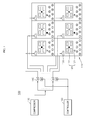
- FIG. 1 is a diagram showing the configuration of a cooling system for two-dimensional array power converters according to a first exemplary embodiment of the present disclosure.
- FIG. 2 is a diagram showing the inner configuration of a power converter employed in the cooling system for two-dimensional array power converters according to the first exemplary embodiment of the present disclosure.
- a cooling system 100 for two-dimensional array power converters includes a plurality of power converters 110 arranged in two-dimension, temperature sensors 120, a compressor 130, valves 140, vortex tubes 150 and a controller 160. It is to be noted that the configuration of the cooling system 100 is not limited to those shown in FIGS. 1 and 2 .
- the cooling system 100 includes the power converters 110, which are arranged in two-dimension.
- the power converters 110 are arranged in a 2-by-3 layout. It is to be understood that the power converters may be arranged in different layouts.
- the power converters 110 are apparatuses that convert the form of power as desired. For example, it may convert the current, voltage, frequency or the like of power.
- the power converters 110 may be inverters for motor drive, solar inverters, ESSs, converters or the like.
- Each of the power converters 110 includes cooling fins 112 installed in the case 111 and semiconductor elements 113 for power conversion.
- the case 111 is of a closed type.
- power converters are of an open type since they include fans.
- the power converters 110 according to the exemplary embodiment of the present disclosure are fabricated as the closed type.
- cooling fins 112 may be disposed at the lowest part of each of the power converters 110 and the semiconductor elements 113 may be disposed above the cooling fins 112.
- a plurality of semiconductor elements 113 for power conversion may be disposed in each of the power converters 110. It is to be noted that the number of the semiconductor elements 113 in each of the power converters 110 may vary.
- the temperature sensors 120 are installed in each of the power converters 110 and measure the temperature inside the power converters 110 to provide it to the controller 160.
- the temperature sensors 120 may include a first temperature sensor 121 installed adjacent to the case 111 to measure the temperature inside the power converters 110, and a second temperature sensor 122 installed adjacent to the semiconductor elements 113 for power conversion.
- the first temperature sensor 121 may be installed in the case 111 of each of the power converters 110 to measure the temperature of the case 111.
- the second temperature sensor 122 may be installed adjacent to the semiconductor elements 113 for power conversion to measure the temperature of the semiconductor elements 113 for power conversion.
- the compressor 130 is to supply compressed air to vortex tubes 150.
- the temperature of a low-temperature air and a high-temperature air generated from the vortex tubes 150 may vary depending on the temperature and the pressure of the compressed air.
- the temperature and the pressure of the compressed air supplied by the compressor 130 may be determined appropriately depending on the use and installation environment of the cooling system 100.
- the compressor 130 may include a pump generating compressed air, and a pressure tank storing the compressed air generated by the pump.
- the valves 140 are installed between the compressor 130 and the vortex tubes 150 and are opened or closed under the control of the controller 160 to control the flow of the compressed air.
- valves 140 are opened under control of the controller 160 to allow the compressed air supplied from the compressor 130 to be supplied to the vortex tubes 150. Or, the valves 140 are closed under control of the controller 160 to block the compressed air supplied from the compressor 130 from being supplied to the vortex tubes 150.
- the compressor 130 is connected to the vortex tubes 150 via pipes.
- the valves 140 may be disposed on the pipes.
- the compressed air is supplied to all of the vortex tubes 150 via the valve, and thus the compressed air may be supplied even to a vortex tube of a power converter which need not to be cooled down.
- the number of the valves is equal to the number of the vortex tubes 150 disposed in the power converters 110.
- a plurality of pipes is disposed to connect the plurality of valves 140 to the plurality of vortex tubes 150.
- the vortex tubes 150 which are also referred to as Ranque-Hilsch vortex tubes, separate the compressed air supplied from the compressor 130 into high-temperature air and low-temperature air.
- one vortex tube is disposed in every power converter.
- this is merely illustrative.
- vortex tubes 150 Details on the shape and design of the vortex tubes 150 are well known in the art, and any of the known vortex tubes may be selected appropriately by those skilled in the art depending on the use purpose and installation environment.
- the low-temperature air generated from the vortex tubes 150 is supplied into the power converters 110 to lower the temperature of the power converters 110.
- each of the vortex tubes 150 is disposed on a location that is appropriate to lower the temperature of the case 111 of the power converters 110 and the semiconductor elements 113.
- vortex tube 150 is disposed in every power converter 110 in this exemplary embodiment of the present disclosure, more than one vortex tubes 150 may be disposed in every power converter 110.
- FIG. 3 is a diagram showing a variant of a cooling system for two-dimensional array power converters according to an exemplary embodiment of the present disclosure.
- each of the power converters 110 may include a plurality of vortex tubes 150.
- the identical elements with those of the cooling system for two-dimensional array power converters shown in FIGS. 1 and 2 will not be described again.
- each of the power converts 110 includes two vortex tubes 150.
- each of the power converts 1110 may include three or more vortex tubes. In the following description, it is assumed that each of the power converts 110 includes two vortex tubes 150.
- the two vortex tubes 150 may include a first vortex tube 151 and a second vortex tube 152.
- the first vortex tube 150 may be installed such that low-temperature air generated from the first vortex tube 151 flows toward the case 111.
- the second vortex tube 152 may be installed close to the semiconductor elements 113 for power conversion so that the temperature of the semiconductor elements 113 is lowered.
- the number of the valves 140 is increased as the number of the vortex tubes 150 increases.
- the controller 160 receives the temperature measured by the temperature sensors 120 and determines whether to supply low temperature air to the power converters 110 by using the vortex tubes 150 based on the received temperature.
- the controller 160 compares the temperature measured by a first temperature sensor 121 (hereinafter referred to as a first temperature) with a first predetermined temperature.
- the first predetermined temperature refers to an appropriate temperature of the case 111 of each of the power converters and may have a certain range.
- the controller 160 determines that low-temperature air has to be supplied to the power converters 110 by using the first vortex tube 151.
- the controller 160 compares the temperature measured by a second temperature sensor 122 (hereinafter referred to as a second temperature) with a second predetermined temperature.
- the second predetermined temperature refers to an appropriate temperature of the semiconductor elements 113 of each of the power converters and may have a certain range.
- the controller 160 determines that low-temperature air has to be supplied to the power converters 110 by using the second vortex tube 152.
- the first and second predetermined temperatures may be determined by those skilled in the art taking into account a system employing them, an installation environment, and the like.
- the first predetermined temperature may be set between 80°C and 100°C
- the second predetermined temperature may be set between 100°C and 120°C.
- the controller 160 controls the valves 140 individually as to whether to supply low-temperature air or not, which is determined based on the temperature measured by the temperature sensors 120 installed in each of the power converters 110.
- the controller 160 stores matching information between the temperature sensors 120 and the valves 140 and determines whether to supply low-temperature air based on the temperature measured by the temperature sensors 120.
- the controller 160 controls one of the valves 140 that is matched with a temperature sensor 120 used in determining whether to supply low-temperature air by referring to the matching information based on the determination.
- the controller 160 transmits a signal to open a valve to the valve 140.
- valves 140 are opened as they receive a signal to open a valve from the controller 160, and the compressed air supplied from the compressor is supplied to the vortex tubes 150 via the valves 140.
- the rate of the low-temperature air supplied by the vortex tubes 150 may be adjusted by the valves. If it is determined that the temperature sensed by the temperature sensors 120 is higher than a predetermined temperature range and thus the valves 140 has to be opened, the controller 160 may adjust the rate by controlling the degree to which valves 140 is opened.
- the rate of the introduced air may be set in advance depending on how much the temperature sensed by the temperature sensors 120 exceeds the predetermined temperature. For example, the rate when the temperature sensed by the temperature sensor 120 exceeds a predetermined temperature by 1°C to 10°C, and the rate when the temperature sensed by the temperature sensor 120 exceeds the predetermined temperature by 11°C to 20°C may be set in advance.
- the controller 160 controls the valves 140 so that the compressed air is introduced at a desired rate depending on how much the temperature sensed by the temperature sensor 120 exceeds the predetermined temperature.
- the controller 160 determines that it is not necessary to supply low temperature to the power converters 110 by using the first vortex tube 151.
- the controller 160 determines that it is not necessary to supply low temperature to the power converters 110 by using the second vortex tube152.
- the controller 160 transmits a signal to close a valve to the valves 140.
- valves 140 are closed as they receive the signal to close a valve from the controller 160, and the compressed air supplied from the compressor is blocked by the valves 140 and is not supplied to the vortex tubes 150.
- the controller 160 determines whether to supply low-temperature air to the power converters 110 by using the vortex tubes 150 based on the temperatures measured by the first and second temperature sensors 121 and 122.
- the controller 160 determines whether to supply the low-temperature air to the power converters 110 by using the vortex tubes 150 based only on the temperature measured by the first temperature sensor 121.
- the controller 160 determines whether to supply the low-temperature air to the power converters 110 by using the vortex tubes 150 based only on the temperature measured by the second temperature sensor 122.
- the power converters 110 when the power converters 110 are cooled down by the cooling system using the vortex tubes 150, the power converters 110 do not require fans. This allows the power converters 110 to be arranged horizontally and vertically, and thus it is possible to reduce the installation space for the power converters.
- the cooling system for two-dimensional array power converters includes no fan
- the power converters may be arranged in two-dimension.
- FIG. 4 is a flowchart for illustrating an operation sequence of the cooling system for two-dimensional array power converters according to an exemplary embodiment of the present disclosure.
- the cooling system 100 is driven, and the temperature sensors 120 and the compressor 130 are operating normally.
- the temperature sensors 120 include first and second temperature sensors 121 and 122. It is assumed that the first temperature sensor 121 is disposed adjacent to the cooling fins 112 and the second temperature sensor 122 is disposed adjacent to the semiconductor elements 113.
- the controller 160 receives first and second temperatures measured by the first and second temperature sensors 121 and 122, respectively (step S310).
- the controller 160 compares the received first and second temperatures with the first and second predetermined temperatures to determine whether the first and second temperatures exceed the first and second predetermined temperatures, respectively (step S320).
- step S320 If it is determined that the received first temperature exceeds the first predetermined temperature or the second temperature exceeds the second predetermined temperature (Yes in step S320), the controller 160 transmits a signal to open a valve to the valves 140 (step S330). If it is determined that the received first temperature does not exceed the first predetermined temperature and the second temperature does not exceed the second predetermined temperature (No in step S320), the controller 160 transmits a signal to close a valve to the valves 140 (step S340).
- valves 140 receive the signal to open a valve in step S330, a valve 140 is opened such that the compressed air is supplied to the vortex tubes 150 (step S350), and the vortex tubes 150 supply low-temperature air to the respective power converter 110 (step S360).
- valves 140 receive the signal to close a valve in step S340, a valve 140 is closed such that the compressed air is blocked and is not supplied to the vortex tubes 150 (step S370), and the vortex tubes 150 do not supply low-temperature air to the respective power converter 110 (step S380).
- the controller 160 transmits the signal to open a valve or the signal to close a valve to the valve matched with the temperature sensor 120 that has transmitted the first temperature or the second temperature.
- the controller 160 may select a valve 140 matched with the temperature sensor 120 based on the matching information between the temperature sensors 120 and the valves 140.
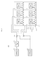
- FIG. 5 is a diagram showing a configuration of a cooling system for two-dimensional array power converters according to a second exemplary embodiment of the present disclosure.
- a cooling system 200 for two-dimensional array power converters includes a plurality of power converters 210 arranged in two-dimension, temperature sensors 220, a compressor 230, valves 240, a vortex tube 250 and a controller 260. It is to be noted that the configuration of the cooling system 200 is not limited to that shown in FIG. 5 .
- each of the plurality of power converters includes at least one vortex tube.
- one vortex tube 250 is installed outside a plurality of power converters and a plurality of valves 240 is disposed between vortex tube 250 and the plurality of power converters 210.
- the cooling system 200 includes the plurality of power converters 210, which are arranged in two-dimension.
- the plurality of power converters 210 are arranged in a 2-by-3 layout.
- the power converters may be arranged in different layouts.
- the power converters 210 are apparatuses that convert the form of power as desired. For example, it may convert the current, voltage, frequency or the like of power.
- the power converters 210 may be inverters for motor drive, solar inverters, ESSs, converters or the like.
- Each of the power converters 210 includes cooling fins 211 installed in the case 212 and semiconductor elements 213 for power conversion.
- the case 211 is of a closed type.
- power converters are of an open type since they include fans.
- the power converters 210 according to the exemplary embodiment of the present disclosure are fabricated as the closed type.
- the cooling fins 212 may be disposed at the lowest part of each of the power converters 210 and the semiconductor elements 213 may be disposed above the cooling fins 212.
- a plurality of semiconductor elements 213 for power conversion may be disposed in each of the power converters 210. It is to be noted that the number of the semiconductor elements 213 in each of the power converters 210 may vary.
- the temperature sensors 220 are installed in each of the power converters 210 and measure the temperature inside the power converters 210 to provide it to the controller 260.
- the temperature sensors 220 may include a first temperature sensor 221 installed adjacent to the case 210 to measure the temperature inside the power converters 211, and a second temperature sensor 222 installed adjacent to the semiconductor elements 213 for power conversion.
- the first temperature sensor 221 may be installed in the case 211 of each of the power converters 210 to measure the temperature of the case 211.
- the second temperature sensor 222 may be installed adjacent to the semiconductor elements 213 for power conversion to measure the temperature of the semiconductor elements 213 for power conversion.
- the compressor 230 is to supply compressed air to vortex tubes 250.
- the temperature of a low-temperature air and a high-temperature air generated from the vortex tubes 250 may vary depending on the temperature and the pressure of the compressed air.
- the temperature and the pressure of the compressed air supplied by the compressor 230 may be determined appropriately depending on the use and installation environment of the cooling system 200.
- the compressor 230 may include, but is not limited to, a pump generating a compressed air, and a pressure tank storing the compressed air generated by the pump.
- the valves 240 are installed between the vortex tube 250 and the plurality of power converters and are opened or closed under the control of the controller 260 to control the flow of the compressed air.
- valves 240 are opened under control of the controller 260 to allow the low-temperature air supplied from the vortex tube 250 to be supplied to each of the power converters 210. Or, the valves 240 are closed under control of the controller 260 to block the low-temperature air supplied from the vortex tube 250 from being supplied to each of the power converters 210.
- the compressor 230, the vortex tube 250 and the power converters are connected to one another via pipes.
- the valves 240 may be disposed on the pipes. The number of the valves 240 is equal to that of the power converters 210.
- the vortex tube 250 separates the compressed air supplied from the compressor 230 into high-temperature air and low-temperature air.
- the low-temperature air generated in the vortex tube 250 is supplied into the power converters 210 via pipes.
- the outlet of each of the pipes is disposed at a location appropriate for lowering the temperatures of the case 211 and the semiconductor elements 213. That is, the outlet may be disposed adjacent to the case 211 or the semiconductor elements 213.
- each of the power converters in the cooling system according to the exemplary embodiments of the present disclosure can be fabricated in a closed type, it is possible to achieve dust-proof capability and explosion-proof capability, thereby allowing applications to a variety of environments.
- each of the power converters can be fabricated in a closed type and fan-less form, it is possible to improve noise-proof capability, thereby allowing a design of low-noise power converters.
Applications Claiming Priority (1)
| Application Number | Priority Date | Filing Date | Title |
|---|---|---|---|
| KR1020160019152A KR20170097421A (ko) | 2016-02-18 | 2016-02-18 | 2차원 배열 전력변환장치용 냉각 시스템 |
Publications (2)
| Publication Number | Publication Date |
|---|---|
| EP3209103A1 true EP3209103A1 (de) | 2017-08-23 |
| EP3209103B1 EP3209103B1 (de) | 2020-01-29 |
Family
ID=57326168
Family Applications (1)
| Application Number | Title | Priority Date | Filing Date |
|---|---|---|---|
| EP16195244.5A Active EP3209103B1 (de) | 2016-02-18 | 2016-10-24 | Kühlsystem für zweidimensionale array-leistungswandler |
Country Status (6)
| Country | Link |
|---|---|
| US (1) | US9949414B2 (de) |
| EP (1) | EP3209103B1 (de) |
| JP (1) | JP6416174B2 (de) |
| KR (1) | KR20170097421A (de) |
| CN (1) | CN107092281B (de) |
| ES (1) | ES2784600T3 (de) |
Cited By (1)
| Publication number | Priority date | Publication date | Assignee | Title |
|---|---|---|---|---|
| FR3128181A1 (fr) * | 2021-10-15 | 2023-04-21 | Alstom Transport Technologies | Système de refroidissement d’équipement(s) électrique(s) embarqué(s) à bord d’un véhicule |
Families Citing this family (3)
| Publication number | Priority date | Publication date | Assignee | Title |
|---|---|---|---|---|
| US10739207B2 (en) * | 2016-05-27 | 2020-08-11 | Nissan Motor Co., Ltd. | Temperature abnormality detection method for power conversion apparatus, and temperature abnormality detection device for power conversion apparatus |
| CN110890829A (zh) * | 2018-09-07 | 2020-03-17 | 中车株洲电力机车研究所有限公司 | 一种用于牵引变流器的内循环冷却系统及其控制方法 |
| KR102503583B1 (ko) * | 2020-12-24 | 2023-02-23 | 재단법인대구경북과학기술원 | 발열 소자 패키지 |
Citations (4)
| Publication number | Priority date | Publication date | Assignee | Title |
|---|---|---|---|---|
| US6108206A (en) * | 1999-06-21 | 2000-08-22 | General Electric Company | Semiconductor thermal protection arrangement |
| EP1467453A2 (de) * | 2003-04-11 | 2004-10-13 | Vacon Oyj | Vorrichtung zur Aufnahme von Frequenzumrichtern |
| US7751188B1 (en) * | 2007-06-29 | 2010-07-06 | Emc Corporation | Method and system for providing cooling of components in a data storage system |
| US20100226090A1 (en) * | 2009-03-03 | 2010-09-09 | International Business Machines Corporation | Temperature control system for an electronic device cabinet |
Family Cites Families (32)
| Publication number | Priority date | Publication date | Assignee | Title |
|---|---|---|---|---|
| JPH085588Y2 (ja) * | 1990-03-09 | 1996-02-14 | 富士通株式会社 | 半導体チップモジュールの冷却構造 |
| US5010736A (en) * | 1990-04-16 | 1991-04-30 | Vortec Corporation | Cooling system for enclosures |
| JPH08316673A (ja) * | 1995-05-17 | 1996-11-29 | Fujitsu Ltd | 冷却構造 |
| JP3214442B2 (ja) * | 1998-04-14 | 2001-10-02 | ダイキン工業株式会社 | 冷熱源ユニット |
| JP4085236B2 (ja) * | 2001-12-12 | 2008-05-14 | 株式会社安川電機 | 冷却機構付きパワーモジュール及びその冷却方法 |
| US6628520B2 (en) * | 2002-02-06 | 2003-09-30 | Hewlett-Packard Development Company, L.P. | Method, apparatus, and system for cooling electronic components |
| KR100461313B1 (ko) | 2002-11-28 | 2004-12-17 | 현대자동차주식회사 | 자동차용 냉방장치 |
| US20040107718A1 (en) * | 2002-12-06 | 2004-06-10 | Michael Bowman | Method, system and apparatus for cooling high power density devices |
| US7012807B2 (en) * | 2003-09-30 | 2006-03-14 | International Business Machines Corporation | Thermal dissipation assembly and fabrication method for electronics drawer of a multiple-drawer electronics rack |
| US6990817B1 (en) * | 2003-12-16 | 2006-01-31 | Sun Microsystems, Inc. | Method and apparatus for cooling electronic equipment within an enclosure |
| SG126909A1 (en) * | 2005-05-02 | 2006-11-29 | Daytona Control Co Ltd | Temperature control apparatus |
| US8051671B2 (en) * | 2005-10-03 | 2011-11-08 | Hewlett-Packard Development Company, L.P. | System and method for cooling computers |
| KR100726461B1 (ko) | 2005-12-21 | 2007-06-11 | 조소곤 | 보텍스 튜브를 이용한 모터 냉각 장치 |
| US7742297B2 (en) * | 2006-04-20 | 2010-06-22 | The Boeing Company | Ceramic foam electronic component cooling |
| JP2008084010A (ja) * | 2006-09-27 | 2008-04-10 | Toshiba Corp | 情報処理装置、情報処理装置の制御方法 |
| US8726681B2 (en) * | 2007-01-23 | 2014-05-20 | Hewlett-Packard Development Company, L.P. | Method and system of cooling components of a computer system |
| US8820095B2 (en) * | 2007-12-21 | 2014-09-02 | Finisar Corporation | Vortex-based temperature control system and method |
| KR20100055236A (ko) * | 2008-11-17 | 2010-05-26 | 삼성전자주식회사 | 반도체 소자 테스트 장치 및 이를 사용한 반도체 소자 테스트 방법 |
| CN102362420A (zh) * | 2009-03-23 | 2012-02-22 | 东芝三菱电机产业系统株式会社 | 功率转换装置 |
| US8570132B2 (en) * | 2009-10-27 | 2013-10-29 | GM Global Technology Operations LLC | Power electronics assembly with multi-sided inductor cooling |
| TWI458034B (zh) * | 2010-01-15 | 2014-10-21 | Advanced Semiconductor Eng | 半導體製造與測試製程之冷卻系統 |
| TWI444130B (zh) * | 2010-01-28 | 2014-07-01 | Delta Electronics Inc | 冷卻系統 |
| US8665591B2 (en) * | 2010-12-21 | 2014-03-04 | General Electric Company | Systems and methods to thermally manage electronic devices |
| CN202195619U (zh) * | 2011-07-26 | 2012-04-18 | 东北电力科学研究院有限公司 | 空气制冷装置 |
| CN202150633U (zh) * | 2011-08-10 | 2012-02-22 | 桂林优西科学仪器有限责任公司 | 波长可调谐激光器系统 |
| KR20130079763A (ko) | 2012-01-03 | 2013-07-11 | 현대모비스 주식회사 | 배터리 냉각장치 및 그 운영방법 |
| JP2014117121A (ja) | 2012-12-12 | 2014-06-26 | Toshiba Corp | 冷却装置及び冷却方法並びに鉄道車両 |
| KR20150025755A (ko) * | 2013-08-30 | 2015-03-11 | 엘에스산전 주식회사 | 인버터 냉각장치 |
| KR101558674B1 (ko) * | 2013-11-22 | 2015-10-07 | 현대자동차주식회사 | 배터리 승온 시스템 및 그 제어 방법 |
| DE112013007670B4 (de) * | 2013-12-04 | 2023-07-06 | Arigna Technology Ltd. | Halbleitervorrichtung |
| CN104090604B (zh) * | 2014-06-30 | 2017-04-05 | 北京七星华创电子股份有限公司 | 热处理设备的温度补偿方法、温度控制方法及系统 |
| CN204993102U (zh) * | 2015-08-14 | 2016-01-20 | Abb技术有限公司 | 功率转换器组件 |
-
2016
- 2016-02-18 KR KR1020160019152A patent/KR20170097421A/ko active IP Right Grant
- 2016-10-24 EP EP16195244.5A patent/EP3209103B1/de active Active
- 2016-10-24 ES ES16195244T patent/ES2784600T3/es active Active
- 2016-11-14 CN CN201611000400.8A patent/CN107092281B/zh active Active
- 2016-11-29 JP JP2016231805A patent/JP6416174B2/ja not_active Expired - Fee Related
-
2017
- 2017-01-19 US US15/410,596 patent/US9949414B2/en active Active
Patent Citations (4)
| Publication number | Priority date | Publication date | Assignee | Title |
|---|---|---|---|---|
| US6108206A (en) * | 1999-06-21 | 2000-08-22 | General Electric Company | Semiconductor thermal protection arrangement |
| EP1467453A2 (de) * | 2003-04-11 | 2004-10-13 | Vacon Oyj | Vorrichtung zur Aufnahme von Frequenzumrichtern |
| US7751188B1 (en) * | 2007-06-29 | 2010-07-06 | Emc Corporation | Method and system for providing cooling of components in a data storage system |
| US20100226090A1 (en) * | 2009-03-03 | 2010-09-09 | International Business Machines Corporation | Temperature control system for an electronic device cabinet |
Cited By (1)
| Publication number | Priority date | Publication date | Assignee | Title |
|---|---|---|---|---|
| FR3128181A1 (fr) * | 2021-10-15 | 2023-04-21 | Alstom Transport Technologies | Système de refroidissement d’équipement(s) électrique(s) embarqué(s) à bord d’un véhicule |
Also Published As
| Publication number | Publication date |
|---|---|
| JP6416174B2 (ja) | 2018-10-31 |
| EP3209103B1 (de) | 2020-01-29 |
| ES2784600T3 (es) | 2020-09-29 |
| CN107092281A (zh) | 2017-08-25 |
| US20170245403A1 (en) | 2017-08-24 |
| JP2017147436A (ja) | 2017-08-24 |
| KR20170097421A (ko) | 2017-08-28 |
| US9949414B2 (en) | 2018-04-17 |
| CN107092281B (zh) | 2019-02-01 |
Similar Documents
| Publication | Publication Date | Title |
|---|---|---|
| US9949414B2 (en) | Cooling system for two-dimensional array power converters | |
| US11300322B2 (en) | Waste-heat recovery system in oil-cooled gas compressor | |
| US10426065B2 (en) | Cooling apparatus for power converter | |
| KR102217341B1 (ko) | 수냉식 냉각장치를 구비한 배터리 시스템 및 이를 위한 유량조절기구 어셈블리 | |
| US20180320927A1 (en) | Waste-Heat Recovery System in Oil-Cooled Gas Compressor | |
| JP6287139B2 (ja) | 電子システム及び電子システムの制御方法 | |
| JP2008217189A (ja) | 電子装置 | |
| US9766668B2 (en) | Forced and natural convection liquid cooler for personal computer | |
| CN112673228B (zh) | 冷却装置及冷却方法 | |
| EP3354119B1 (de) | Kühlanordnung zum beispiel zur kühlung einer wandlerventilhalle | |
| KR20170092869A (ko) | 보텍스 튜브를 이용한 냉각 시스템의 동작방법 | |
| KR101488003B1 (ko) | 컨버터 냉각 시스템 | |
| KR20170097417A (ko) | 전력변환장치용 냉각 시스템 | |
| WO2015084539A1 (en) | System and method for controlling temperature of a working fluid | |
| US20220149700A1 (en) | Multi-fan mobile gas generator cooling system | |
| CN218030932U (zh) | 液压系统的温度控制系统和气体压缩系统 | |
| US20130240196A1 (en) | Container with cooling system | |
| KR20230111538A (ko) | 연료전지 시스템 | |
| CN114745930A (zh) | 液冷机柜设备及其控制方法 | |
| JP2019168218A (ja) | 排熱回収システム | |
| JP2016191386A (ja) | ガス圧縮機 | |
| CN107248506A (zh) | 一种晶匣管散热结构 |
Legal Events
| Date | Code | Title | Description |
|---|---|---|---|
| PUAI | Public reference made under article 153(3) epc to a published international application that has entered the european phase |
Free format text: ORIGINAL CODE: 0009012 |
|
| STAA | Information on the status of an ep patent application or granted ep patent |
Free format text: STATUS: THE APPLICATION HAS BEEN PUBLISHED |
|
| AK | Designated contracting states |
Kind code of ref document: A1 Designated state(s): AL AT BE BG CH CY CZ DE DK EE ES FI FR GB GR HR HU IE IS IT LI LT LU LV MC MK MT NL NO PL PT RO RS SE SI SK SM TR |
|
| AX | Request for extension of the european patent |
Extension state: BA ME |
|
| STAA | Information on the status of an ep patent application or granted ep patent |
Free format text: STATUS: REQUEST FOR EXAMINATION WAS MADE |
|
| 17P | Request for examination filed |
Effective date: 20180216 |
|
| RBV | Designated contracting states (corrected) |
Designated state(s): AL AT BE BG CH CY CZ DE DK EE ES FI FR GB GR HR HU IE IS IT LI LT LU LV MC MK MT NL NO PL PT RO RS SE SI SK SM TR |
|
| GRAP | Despatch of communication of intention to grant a patent |
Free format text: ORIGINAL CODE: EPIDOSNIGR1 |
|
| STAA | Information on the status of an ep patent application or granted ep patent |
Free format text: STATUS: GRANT OF PATENT IS INTENDED |
|
| INTG | Intention to grant announced |
Effective date: 20190927 |
|
| GRAS | Grant fee paid |
Free format text: ORIGINAL CODE: EPIDOSNIGR3 |
|
| GRAA | (expected) grant |
Free format text: ORIGINAL CODE: 0009210 |
|
| STAA | Information on the status of an ep patent application or granted ep patent |
Free format text: STATUS: THE PATENT HAS BEEN GRANTED |
|
| AK | Designated contracting states |
Kind code of ref document: B1 Designated state(s): AL AT BE BG CH CY CZ DE DK EE ES FI FR GB GR HR HU IE IS IT LI LT LU LV MC MK MT NL NO PL PT RO RS SE SI SK SM TR |
|
| REG | Reference to a national code |
Ref country code: GB Ref legal event code: FG4D |
|
| REG | Reference to a national code |
Ref country code: CH Ref legal event code: EP |
|
| REG | Reference to a national code |
Ref country code: AT Ref legal event code: REF Ref document number: 1229289 Country of ref document: AT Kind code of ref document: T Effective date: 20200215 |
|
| REG | Reference to a national code |
Ref country code: IE Ref legal event code: FG4D |
|
| REG | Reference to a national code |
Ref country code: DE Ref legal event code: R096 Ref document number: 602016028611 Country of ref document: DE |
|
| REG | Reference to a national code |
Ref country code: NL Ref legal event code: MP Effective date: 20200129 |
|
| PG25 | Lapsed in a contracting state [announced via postgrant information from national office to epo] |
Ref country code: PT Free format text: LAPSE BECAUSE OF FAILURE TO SUBMIT A TRANSLATION OF THE DESCRIPTION OR TO PAY THE FEE WITHIN THE PRESCRIBED TIME-LIMIT Effective date: 20200621 Ref country code: NO Free format text: LAPSE BECAUSE OF FAILURE TO SUBMIT A TRANSLATION OF THE DESCRIPTION OR TO PAY THE FEE WITHIN THE PRESCRIBED TIME-LIMIT Effective date: 20200429 Ref country code: FI Free format text: LAPSE BECAUSE OF FAILURE TO SUBMIT A TRANSLATION OF THE DESCRIPTION OR TO PAY THE FEE WITHIN THE PRESCRIBED TIME-LIMIT Effective date: 20200129 Ref country code: RS Free format text: LAPSE BECAUSE OF FAILURE TO SUBMIT A TRANSLATION OF THE DESCRIPTION OR TO PAY THE FEE WITHIN THE PRESCRIBED TIME-LIMIT Effective date: 20200129 |
|
| REG | Reference to a national code |
Ref country code: LT Ref legal event code: MG4D |
|
| PG25 | Lapsed in a contracting state [announced via postgrant information from national office to epo] |
Ref country code: IS Free format text: LAPSE BECAUSE OF FAILURE TO SUBMIT A TRANSLATION OF THE DESCRIPTION OR TO PAY THE FEE WITHIN THE PRESCRIBED TIME-LIMIT Effective date: 20200529 Ref country code: SE Free format text: LAPSE BECAUSE OF FAILURE TO SUBMIT A TRANSLATION OF THE DESCRIPTION OR TO PAY THE FEE WITHIN THE PRESCRIBED TIME-LIMIT Effective date: 20200129 Ref country code: HR Free format text: LAPSE BECAUSE OF FAILURE TO SUBMIT A TRANSLATION OF THE DESCRIPTION OR TO PAY THE FEE WITHIN THE PRESCRIBED TIME-LIMIT Effective date: 20200129 Ref country code: LV Free format text: LAPSE BECAUSE OF FAILURE TO SUBMIT A TRANSLATION OF THE DESCRIPTION OR TO PAY THE FEE WITHIN THE PRESCRIBED TIME-LIMIT Effective date: 20200129 Ref country code: GR Free format text: LAPSE BECAUSE OF FAILURE TO SUBMIT A TRANSLATION OF THE DESCRIPTION OR TO PAY THE FEE WITHIN THE PRESCRIBED TIME-LIMIT Effective date: 20200430 Ref country code: BG Free format text: LAPSE BECAUSE OF FAILURE TO SUBMIT A TRANSLATION OF THE DESCRIPTION OR TO PAY THE FEE WITHIN THE PRESCRIBED TIME-LIMIT Effective date: 20200429 |
|
| REG | Reference to a national code |
Ref country code: ES Ref legal event code: FG2A Ref document number: 2784600 Country of ref document: ES Kind code of ref document: T3 Effective date: 20200929 |
|
| PG25 | Lapsed in a contracting state [announced via postgrant information from national office to epo] |
Ref country code: NL Free format text: LAPSE BECAUSE OF FAILURE TO SUBMIT A TRANSLATION OF THE DESCRIPTION OR TO PAY THE FEE WITHIN THE PRESCRIBED TIME-LIMIT Effective date: 20200129 |
|
| PG25 | Lapsed in a contracting state [announced via postgrant information from national office to epo] |
Ref country code: LT Free format text: LAPSE BECAUSE OF FAILURE TO SUBMIT A TRANSLATION OF THE DESCRIPTION OR TO PAY THE FEE WITHIN THE PRESCRIBED TIME-LIMIT Effective date: 20200129 Ref country code: DK Free format text: LAPSE BECAUSE OF FAILURE TO SUBMIT A TRANSLATION OF THE DESCRIPTION OR TO PAY THE FEE WITHIN THE PRESCRIBED TIME-LIMIT Effective date: 20200129 Ref country code: SM Free format text: LAPSE BECAUSE OF FAILURE TO SUBMIT A TRANSLATION OF THE DESCRIPTION OR TO PAY THE FEE WITHIN THE PRESCRIBED TIME-LIMIT Effective date: 20200129 Ref country code: EE Free format text: LAPSE BECAUSE OF FAILURE TO SUBMIT A TRANSLATION OF THE DESCRIPTION OR TO PAY THE FEE WITHIN THE PRESCRIBED TIME-LIMIT Effective date: 20200129 Ref country code: RO Free format text: LAPSE BECAUSE OF FAILURE TO SUBMIT A TRANSLATION OF THE DESCRIPTION OR TO PAY THE FEE WITHIN THE PRESCRIBED TIME-LIMIT Effective date: 20200129 Ref country code: CZ Free format text: LAPSE BECAUSE OF FAILURE TO SUBMIT A TRANSLATION OF THE DESCRIPTION OR TO PAY THE FEE WITHIN THE PRESCRIBED TIME-LIMIT Effective date: 20200129 Ref country code: SK Free format text: LAPSE BECAUSE OF FAILURE TO SUBMIT A TRANSLATION OF THE DESCRIPTION OR TO PAY THE FEE WITHIN THE PRESCRIBED TIME-LIMIT Effective date: 20200129 |
|
| PGFP | Annual fee paid to national office [announced via postgrant information from national office to epo] |
Ref country code: FR Payment date: 20200910 Year of fee payment: 5 |
|
| REG | Reference to a national code |
Ref country code: DE Ref legal event code: R097 Ref document number: 602016028611 Country of ref document: DE |
|
| REG | Reference to a national code |
Ref country code: AT Ref legal event code: MK05 Ref document number: 1229289 Country of ref document: AT Kind code of ref document: T Effective date: 20200129 |
|
| PLBE | No opposition filed within time limit |
Free format text: ORIGINAL CODE: 0009261 |
|
| STAA | Information on the status of an ep patent application or granted ep patent |
Free format text: STATUS: NO OPPOSITION FILED WITHIN TIME LIMIT |
|
| 26N | No opposition filed |
Effective date: 20201030 |
|
| PG25 | Lapsed in a contracting state [announced via postgrant information from national office to epo] |
Ref country code: AT Free format text: LAPSE BECAUSE OF FAILURE TO SUBMIT A TRANSLATION OF THE DESCRIPTION OR TO PAY THE FEE WITHIN THE PRESCRIBED TIME-LIMIT Effective date: 20200129 |
|
| PG25 | Lapsed in a contracting state [announced via postgrant information from national office to epo] |
Ref country code: PL Free format text: LAPSE BECAUSE OF FAILURE TO SUBMIT A TRANSLATION OF THE DESCRIPTION OR TO PAY THE FEE WITHIN THE PRESCRIBED TIME-LIMIT Effective date: 20200129 Ref country code: SI Free format text: LAPSE BECAUSE OF FAILURE TO SUBMIT A TRANSLATION OF THE DESCRIPTION OR TO PAY THE FEE WITHIN THE PRESCRIBED TIME-LIMIT Effective date: 20200129 |
|
| REG | Reference to a national code |
Ref country code: CH Ref legal event code: PL |
|
| PG25 | Lapsed in a contracting state [announced via postgrant information from national office to epo] |
Ref country code: MC Free format text: LAPSE BECAUSE OF FAILURE TO SUBMIT A TRANSLATION OF THE DESCRIPTION OR TO PAY THE FEE WITHIN THE PRESCRIBED TIME-LIMIT Effective date: 20200129 Ref country code: LU Free format text: LAPSE BECAUSE OF NON-PAYMENT OF DUE FEES Effective date: 20201024 |
|
| REG | Reference to a national code |
Ref country code: BE Ref legal event code: MM Effective date: 20201031 |
|
| PG25 | Lapsed in a contracting state [announced via postgrant information from national office to epo] |
Ref country code: BE Free format text: LAPSE BECAUSE OF NON-PAYMENT OF DUE FEES Effective date: 20201031 Ref country code: CH Free format text: LAPSE BECAUSE OF NON-PAYMENT OF DUE FEES Effective date: 20201031 Ref country code: LI Free format text: LAPSE BECAUSE OF NON-PAYMENT OF DUE FEES Effective date: 20201031 |
|
| PG25 | Lapsed in a contracting state [announced via postgrant information from national office to epo] |
Ref country code: IE Free format text: LAPSE BECAUSE OF NON-PAYMENT OF DUE FEES Effective date: 20201024 |
|
| PG25 | Lapsed in a contracting state [announced via postgrant information from national office to epo] |
Ref country code: TR Free format text: LAPSE BECAUSE OF FAILURE TO SUBMIT A TRANSLATION OF THE DESCRIPTION OR TO PAY THE FEE WITHIN THE PRESCRIBED TIME-LIMIT Effective date: 20200129 Ref country code: MT Free format text: LAPSE BECAUSE OF FAILURE TO SUBMIT A TRANSLATION OF THE DESCRIPTION OR TO PAY THE FEE WITHIN THE PRESCRIBED TIME-LIMIT Effective date: 20200129 Ref country code: CY Free format text: LAPSE BECAUSE OF FAILURE TO SUBMIT A TRANSLATION OF THE DESCRIPTION OR TO PAY THE FEE WITHIN THE PRESCRIBED TIME-LIMIT Effective date: 20200129 |
|
| PG25 | Lapsed in a contracting state [announced via postgrant information from national office to epo] |
Ref country code: MK Free format text: LAPSE BECAUSE OF FAILURE TO SUBMIT A TRANSLATION OF THE DESCRIPTION OR TO PAY THE FEE WITHIN THE PRESCRIBED TIME-LIMIT Effective date: 20200129 Ref country code: AL Free format text: LAPSE BECAUSE OF FAILURE TO SUBMIT A TRANSLATION OF THE DESCRIPTION OR TO PAY THE FEE WITHIN THE PRESCRIBED TIME-LIMIT Effective date: 20200129 |
|
| PG25 | Lapsed in a contracting state [announced via postgrant information from national office to epo] |
Ref country code: FR Free format text: LAPSE BECAUSE OF NON-PAYMENT OF DUE FEES Effective date: 20211031 |
|
| PGFP | Annual fee paid to national office [announced via postgrant information from national office to epo] |
Ref country code: IT Payment date: 20220906 Year of fee payment: 7 Ref country code: GB Payment date: 20220905 Year of fee payment: 7 |
|
| PGFP | Annual fee paid to national office [announced via postgrant information from national office to epo] |
Ref country code: ES Payment date: 20221114 Year of fee payment: 7 Ref country code: DE Payment date: 20220603 Year of fee payment: 7 |