EP3208457B1 - Peltonrad - Google Patents
Peltonrad Download PDFInfo
- Publication number
- EP3208457B1 EP3208457B1 EP16205343.3A EP16205343A EP3208457B1 EP 3208457 B1 EP3208457 B1 EP 3208457B1 EP 16205343 A EP16205343 A EP 16205343A EP 3208457 B1 EP3208457 B1 EP 3208457B1
- Authority
- EP
- European Patent Office
- Prior art keywords
- screw
- expansion
- wheel disk
- bolt
- cup
- Prior art date
- Legal status (The legal status is an assumption and is not a legal conclusion. Google has not performed a legal analysis and makes no representation as to the accuracy of the status listed.)
- Active
Links
Images




Classifications
-
- F—MECHANICAL ENGINEERING; LIGHTING; HEATING; WEAPONS; BLASTING
- F16—ENGINEERING ELEMENTS AND UNITS; GENERAL MEASURES FOR PRODUCING AND MAINTAINING EFFECTIVE FUNCTIONING OF MACHINES OR INSTALLATIONS; THERMAL INSULATION IN GENERAL
- F16B—DEVICES FOR FASTENING OR SECURING CONSTRUCTIONAL ELEMENTS OR MACHINE PARTS TOGETHER, e.g. NAILS, BOLTS, CIRCLIPS, CLAMPS, CLIPS OR WEDGES; JOINTS OR JOINTING
- F16B13/00—Dowels or other devices fastened in walls or the like by inserting them in holes made therein for that purpose
- F16B13/04—Dowels or other devices fastened in walls or the like by inserting them in holes made therein for that purpose with parts gripping in the hole or behind the reverse side of the wall after inserting from the front
-
- F—MECHANICAL ENGINEERING; LIGHTING; HEATING; WEAPONS; BLASTING
- F03—MACHINES OR ENGINES FOR LIQUIDS; WIND, SPRING, OR WEIGHT MOTORS; PRODUCING MECHANICAL POWER OR A REACTIVE PROPULSIVE THRUST, NOT OTHERWISE PROVIDED FOR
- F03B—MACHINES OR ENGINES FOR LIQUIDS
- F03B1/00—Engines of impulse type, i.e. turbines with jets of high-velocity liquid impinging on blades or like rotors, e.g. Pelton wheels; Parts or details peculiar thereto
- F03B1/02—Buckets; Bucket-carrying rotors
-
- F—MECHANICAL ENGINEERING; LIGHTING; HEATING; WEAPONS; BLASTING
- F03—MACHINES OR ENGINES FOR LIQUIDS; WIND, SPRING, OR WEIGHT MOTORS; PRODUCING MECHANICAL POWER OR A REACTIVE PROPULSIVE THRUST, NOT OTHERWISE PROVIDED FOR
- F03B—MACHINES OR ENGINES FOR LIQUIDS
- F03B3/00—Machines or engines of reaction type; Parts or details peculiar thereto
- F03B3/12—Blades; Blade-carrying rotors
- F03B3/128—Mounting, demounting
-
- F—MECHANICAL ENGINEERING; LIGHTING; HEATING; WEAPONS; BLASTING
- F05—INDEXING SCHEMES RELATING TO ENGINES OR PUMPS IN VARIOUS SUBCLASSES OF CLASSES F01-F04
- F05B—INDEXING SCHEME RELATING TO WIND, SPRING, WEIGHT, INERTIA OR LIKE MOTORS, TO MACHINES OR ENGINES FOR LIQUIDS COVERED BY SUBCLASSES F03B, F03D AND F03G
- F05B2230/00—Manufacture
- F05B2230/60—Assembly methods
-
- F—MECHANICAL ENGINEERING; LIGHTING; HEATING; WEAPONS; BLASTING
- F05—INDEXING SCHEMES RELATING TO ENGINES OR PUMPS IN VARIOUS SUBCLASSES OF CLASSES F01-F04
- F05B—INDEXING SCHEME RELATING TO WIND, SPRING, WEIGHT, INERTIA OR LIKE MOTORS, TO MACHINES OR ENGINES FOR LIQUIDS COVERED BY SUBCLASSES F03B, F03D AND F03G
- F05B2230/00—Manufacture
- F05B2230/80—Repairing, retrofitting or upgrading methods
-
- F—MECHANICAL ENGINEERING; LIGHTING; HEATING; WEAPONS; BLASTING
- F05—INDEXING SCHEMES RELATING TO ENGINES OR PUMPS IN VARIOUS SUBCLASSES OF CLASSES F01-F04
- F05B—INDEXING SCHEME RELATING TO WIND, SPRING, WEIGHT, INERTIA OR LIKE MOTORS, TO MACHINES OR ENGINES FOR LIQUIDS COVERED BY SUBCLASSES F03B, F03D AND F03G
- F05B2260/00—Function
- F05B2260/30—Retaining components in desired mutual position
-
- Y—GENERAL TAGGING OF NEW TECHNOLOGICAL DEVELOPMENTS; GENERAL TAGGING OF CROSS-SECTIONAL TECHNOLOGIES SPANNING OVER SEVERAL SECTIONS OF THE IPC; TECHNICAL SUBJECTS COVERED BY FORMER USPC CROSS-REFERENCE ART COLLECTIONS [XRACs] AND DIGESTS
- Y02—TECHNOLOGIES OR APPLICATIONS FOR MITIGATION OR ADAPTATION AGAINST CLIMATE CHANGE
- Y02E—REDUCTION OF GREENHOUSE GAS [GHG] EMISSIONS, RELATED TO ENERGY GENERATION, TRANSMISSION OR DISTRIBUTION
- Y02E10/00—Energy generation through renewable energy sources
- Y02E10/20—Hydro energy
-
- Y—GENERAL TAGGING OF NEW TECHNOLOGICAL DEVELOPMENTS; GENERAL TAGGING OF CROSS-SECTIONAL TECHNOLOGIES SPANNING OVER SEVERAL SECTIONS OF THE IPC; TECHNICAL SUBJECTS COVERED BY FORMER USPC CROSS-REFERENCE ART COLLECTIONS [XRACs] AND DIGESTS
- Y02—TECHNOLOGIES OR APPLICATIONS FOR MITIGATION OR ADAPTATION AGAINST CLIMATE CHANGE
- Y02P—CLIMATE CHANGE MITIGATION TECHNOLOGIES IN THE PRODUCTION OR PROCESSING OF GOODS
- Y02P70/00—Climate change mitigation technologies in the production process for final industrial or consumer products
- Y02P70/50—Manufacturing or production processes characterised by the final manufactured product
Definitions
- the invention relates to a Peltonrad with a wheel disc and with separately made cups that are cast or made of solid and releasably secured to the wheel disc, wherein the attachment by means of at least one screw or at least one bolt takes place, or perpendicular to the axis of rotation Wheel disc arranged and fixed to the wheel disc.
- Pelton wheels There are several different processes for producing Pelton wheels. An elaborate method is the working out of the Pelton cups from a full blank, whereby about 60 - 70% material is lost. In other methods such as HIWELD or MICROGUSS (eg EP 960181 ) cups are welded to appropriately prepared wheel discs. Furthermore, has long been, inter alia, from the GB 174,768 or CH 111442 known to attach individual cups by means of axial screws to corresponding shaped parts of a wheel disc. To be stable here but the cup must be provided with appropriate extensions through which the screws can be performed and the wheel must have corresponding extensions. Also, it has long been known to use screws or bolts in the radial direction, such as in the AT96298B . US1361467A .
- the aim of the invention is therefore to provide a simple and cost-effective production for a Pelton runner, which also enables economical and safe maintenance.
- the invention is therefore characterized in that the at least one screw or the at least one bolt is designed as an expansion screw or expansion bolt, wherein the expansion screw or the expansion bolt is controlled biased and each cup has at least one expansion screw or expansion bolt, each Cup is positively connected via at least one radially aligned with the axis of rotation of the wheel disc Scherbüchse with the wheel disc.
- the wheel disc and the cup can be made very easily and inexpensively. Due to the shear bolts as positive locking elements and the screw connection can be relieved of the tangential dynamic forces.
- a favorable development of the invention is characterized in that the expansion screw or the expansion bolt is biased in conjunction with a nut.
- the expansion screw or the expansion bolt can be biased to the extent that eliminates the life-damaging dynamic operating forces by the jet engagement on the expansion screw or the expansion bolt.
- each cup is positively connected via further radially aligned to the axis of rotation shear bolt with the wheel disc.
- a favorable embodiment of the invention is characterized in that the expansion screw or expansion bolts initiate the radial centrifugal forces and the shear pins introduce the tangential jet forces into the wheel disc.
- the tangential and radial operating forces can be introduced separately and the individual parts are designed specifically for this load.
- expansion screw has a cover at its free end. So it can be protected from abrasive water, which extends the life.
- a favorable development of the invention is characterized in that the expansion screw or the expansion bolt from the inside, ie from the axial direction of the wheel disc, is screwed. This allows a particularly advantageous protection of the screw connection from the process water.
- An advantageous embodiment of the invention is characterized in that two or more cups are combined into a respective cup unit and fastened by means of a common expansion screw on the wheel disc.
- Fig. 1 shows a 3D representation of a wheel disc 1 of a Pelton wheel with mounted cups 2 and the exploded view of a cup 2 with inventive attachment.
- the screw 5 is guided through a corresponding bore of the cup 2, surrounded by a bushing 4 and screwed in a bore 8 of the wheel disc 1 under bias.
- shear bolts 3 are inserted into corresponding holes 9 of the wheel disc 1 and corresponding holes in the cup 2.
- the water is injected through nozzles onto the cups 2. This water jet is split on the cups 2 in two parts. Both parts of the water steel follow the course of the inner surface of the cup 2 until the water leaves the cup again. Due to the change in direction of the water jet, an impulse force is exerted on the cup 2 or the impeller.
- Fig. 1 a shows an enlarged section Fig. 1 in which a part of the wheel disc 1, two cups 2 and another cup 2 with the fastening means screw 5, socket 4, shear pin 3 and cover 6 with screw 7 can be seen.
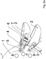
- Fig. 2 shows a view of a wheel disc 1 in the axial direction with mounted cups 2 and sections in the region of the attachment. It can be seen again the wheel disc 1, a number of cups 2 and the example of two cups in different cutting plane, the screw 5 in the bore 8 with socket 4 and cover 6 with screw 7. In another cup 2, the cutting plane through the shear pin. 3 and hole 9 laid.
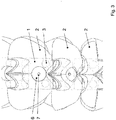
- Fig. 3 represents a view of the cup 2 in the radial direction.
- the upper complete cup 2 can be seen the two shear pin 3 and the cover 6 and mounting screw 7 on the screw 5 (not visible here). This arrangement is located on the lower side of the cup 2.
- Fig. 4 shows the said construction with an attached from the inside of the wheel disc 1 ago screw.
- the advantage of this variant is that the cup-side covers omitted and the screw can be very easily protected or sealed against abrasive particles and water.
- Fig. 5 shows a view of summarized cup units.
- two cups are combined into a cup unit.
- These cup units are each attached to the wheel disc 1 with only one screw 5.
- This type of arrangement represents an alternative to the previously discussed construction. This alternative combines the advantages described above with a reduced assembly time with respect to cup change or conversion to a modified hydraulic cup contour.
Landscapes
- Engineering & Computer Science (AREA)
- General Engineering & Computer Science (AREA)
- Mechanical Engineering (AREA)
- Chemical & Material Sciences (AREA)
- Combustion & Propulsion (AREA)
- Hydraulic Turbines (AREA)
- Polishing Bodies And Polishing Tools (AREA)
Description
- Die Erfindung betrifft ein Peltonrad mit einer Radscheibe und mit separat gefertigten Bechern, die gegossen oder aus dem Vollen gefertigt und lösbar an der Radscheibe befestigt sind, wobei die Befestigung mittels zumindest einer Schraube oder mindestens einem Bolzen erfolgt, die bzw. der senkrecht zur Drehachse der Radscheibe angeordnet und an der Radscheibe befestigt ist.
- Zur Herstellung von Peltonrädern gibt es mehrere unterschiedliche Verfahren. Eine aufwändige Methode ist das Herausarbeiten der Peltonbecher aus einem vollen Rohling, wodurch ca. 60 - 70% Material verloren gehen. Bei anderen Verfahren wie z.B. HIWELD oder MICROGUSS (z.B.
EP 960181 GB 174,768 CH 111442 AT96298B US1361467A ,JP2012127333A FR480562A US617555A oderAT33591B - Ziel der Erfindung ist es daher eine einfache und kostengünstige Herstellung für ein Peltonlaufrad zu schaffen, die auch eine wirtschaftliche und sichere Instandhaltung ermöglicht.
- Die Erfindung ist daher dadurch gekennzeichnet, dass die mindestens eine Schraube oder der mindestens eine Bolzen als Dehnschraube oder Dehnbolzen ausgeführt ist, wobei die Dehnschraube oder der Dehnbolzen kontrolliert vorgespannt ist und jeder Becher mindestens eine Dehnschraube oder Dehnbolzenaufweist, wobei jeder Becher über mindestens eine radial zur Drehachse der Radscheibe ausgerichtete Scherbüchse mit der Radscheibe formschlüssig verbunden ist. Dadurch können sowohl die Radscheibe wie auch die Becher sehr einfach und kostengünstig hergestellt werden. Durch die Scherbolzen als Formschlusselemente kann auch die Schraubenverbindung von den tangential wirkenden dynamischen Kräften entlastet werden.
- Eine günstige Weiterbildung der Erfindung ist dadurch gekennzeichnet, dass die Dehnschraube bzw. der Dehnbolzen in Verbindung mit einer Mutter vorgespannt ist. Dadurch können die durch die Rotation auftretenden Kräfte ohne Zusatzmaßnahmen besonders gut beherrscht werden. Die Dehnschraube oder der Dehnbolzenkönnen dabei soweit vorgespannt werden, dass die lebensdauerschädigenden dynamischen Betriebskräfte durch den Strahleingriff auf die Dehnschraube oder den Dehnbolzen entfallen.
- Eine vorteilhafte Ausgestaltung der Erfindung ist dadurch gekennzeichnet, dass jeder Becher über weitere radial zur Drehachse ausgerichtete Scherbolzen mit der Radscheibe formschlüssig verbunden ist. Damit können besonders gut die tangentialen Kräfte aus den Wasserstrahlen aufgenommen werden. Gemeinsam mit den vorgespannten Schrauben kann so die dynamische Belastung der Schrauben auf einem sehr niedrigen Niveau gehalten werden und die Schrauben aus kostengünstigem Material gefertigt werden.
- Eine günstige Ausgestaltung der Erfindung ist dadurch gekennzeichnet, dass die Dehnschraube oder Dehnbolzen die radialen Fliehkräfte und die Scherbolzen die tangentialen Strahlkräfte in die Radscheibe einleiten. So können die tangentialen und radialen Betriebskräfte getrennt eingeleitet werden und die einzelnen Teile speziell auf diese Belastung ausgelegt werden.
- Eine vorteilhafte Weiterbildung der Erfindung ist dadurch gekennzeichnet, dass die Dehnschraube an ihrem freien Ende eine Abdeckung aufweist. Damit kann sie vor abrasivem Wasser geschützt werden, was die Lebensdauer verlängert.
- Eine günstige Weiterbildung der Erfindung ist dadurch gekennzeichnet, dass die Dehnschraube oder der Dehnbolzen von innen, d.h. aus Achsrichtung der Radscheibe, eingeschraubt wird. Dies ermöglicht einen besonders vorteilhaften Schutz der Schraubenverbindung vor dem Betriebswasser.
- Eine vorteilhafte Ausgestaltung der Erfindung ist dadurch gekennzeichnet, dass zwei oder mehr Becher zu jeweils einer Bechereinheit zusammengefasst und mittels einer gemeinsamen Dehnschraube an der Radscheibe befestigt sind. Damit lässt sich die Anzahl der zu montierenden Teile und damit auch die Montagezeit stark reduzieren.
- Die Erfindung wird nun anhand der Zeichnungen beispielhaft beschrieben, wobei
-
Fig. 1 eine 3D Darstellung einer Radscheibe mit montierten Bechern sowie der Explosionsansicht eines Bechers mit erfindungsgemäßer Befestigung, -
Fig. 1 a einen vergrößerten Ausschnitt ausFig. 1 , -
Fig. 2 eine Ansicht einer Radscheibe in axialer Richtung mit montierten Bechern sowie Schnitten im Bereich der Befestigung, -
Fig. 2 a einen vergrößerten Ausschnitt ausFig. 2 , -
Fig. 3 eine Ansicht eines Ausschnittes einer Radscheibe mit montierten Bechern in radialer Richtung -
Fig. 4 eine Ansicht einer der Verschraubungsvariante von der Innenseite der Radscheibe -
Fig. 5 eine Ansicht von zusammengefassten Bechereinheiten
darstellt. -
Fig. 1 zeigt eine 3D Darstellung einer Radscheibe 1 eines Peltonrades mit montierten Bechern 2 sowie der Explosionsansicht eines Bechers 2 mit erfindungsgemäßer Befestigung. Die Schraube 5 wird durch eine entsprechende Bohrung des Bechers 2 geführt, von einer Buchse 4 umgeben und in einer Bohrung 8 der Radscheibe 1 unter Vorspannung verschraubt. Daneben werden Scherbolzen 3 in entsprechende Löcher 9 der Radscheibe 1 und entsprechende Bohrungen im Becher 2 eingesetzt. Wie bei allen Pelton-Turbinen wird das Wasser durch Düsen auf die Becher 2 eingespritzt. Dieser Wasserstrahl wird auf den Bechern 2 in zwei Teile aufgeteilt. Beide Teile des Wasserstahls folgen dem Verlauf der inneren Oberfläche der Becher 2 bis das Wasser den Becher wieder verlässt. Durch die Richtungsänderung des Wasserstrahls wird eine Impulskraft auf den Becher 2 bzw. das Laufrad ausgeübt. - Diese Kraft wird nun durch die Scherbolzen 3 und Buchsen 4 auf die Radscheibe 1 übertragen. Die vorgespannten Schrauben 5 tragen im Wesentlichen die durch die Rotation entstehenden Zentrifugalkräfte der Pelton-Becher 2. Durch eine Schraube 7 wird eine Abdeckung 6 mit der Schraube 5 verbunden, um letztere vor abrasivem Wasser zu schützen.
-
Fig. 1 a stellt einen vergrößerten Ausschnitt ausFig. 1 dar, in dem ein Teil der Radscheibe 1, zwei Becher 2 sowie ein weiterer Becher 2 mit den Befestigungsmitteln Schraube 5, Buchse 4, Scherbolzen 3 sowie Abdeckung 6 mit Schraube 7 erkennbar sind. -
Fig. 2 zeigt eine Ansicht einer Radscheibe 1 in axialer Richtung mit montierten Bechern 2 sowie Schnitten im Bereich der Befestigung. Man erkennt hier wiederum die Radscheibe 1, eine Anzahl Becher 2 und am Beispiel von zwei Bechern in unterschiedlicher Schnittebene die Schraube 5 in der Bohrung 8 mit Buchse 4 sowie Abdeckung 6 mit Schraube 7. Bei einem weiteren Becher 2 ist die Schnittebene durch den Scherbolzen 3 und Bohrung 9 gelegt. - Die Einzelheiten sind in
Fig. 2 a als vergrößertem Ausschnitt ausFig. 2 besser erkennbar. Hier kann man auch erkennen, dass die Buchse 4 zwischen Schraube 5 und Radscheibe 1 sowie Becher 2 angeordnet ist und somit die an der Kontaktfläche von Radscheibe 1 und Becher 2 auftretenden Scherkräfte aufnimmt. Analog nehmen die Scherbolzen 3 Scherkräfte zwischen Radscheibe 1 und Becher 2 auf. -
Fig. 3 stellt eine Ansicht der Becher 2 in radialer Richtung dar. Beim oberen vollständigen Becher 2 erkennt man die beiden Scherbolzen 3 sowie die Abdeckung 6 und Befestigungsschraube 7 über der Schraube 5 (hier nicht sichtbar). Diese Anordnung befindet sich auf der unteren Seite der Becher 2. - Durch diese Art der Befestigung wird es auch ermöglicht, dass einzelne Becher, die durch Abrasion verschlissen sind, ausgetauscht werden können, ohne die übrigen Becher zu demontieren. Es wird auch ermöglicht in einfacher Weise die Becher auszutauschen und Becher mit unterschiedlichen Geometrien entsprechend geänderten hydraulischen Anforderungen einzusetzen. Durch den Entfall der bisher konstruktiv benötigten Fortsätze der Becher, die an diesen Stellen besonders hohen Kräften und Abrasion ausgesetzt sind, können robustere Becher eingesetzt werden. Auch die Reparaturnotwendigkeit in den Bereichen hoher Kräfte entfällt.
-
Fig. 4 zeigt die genannte Konstruktion mit einer von der Innenseite der Radscheibe 1 her angebrachten Verschraubung. Der Vorteil dieser Variante ist, dass die becherseitigen Abdeckungen entfallen und die Verschraubung sehr einfach gegen abrasive Partikel und Wasser geschützt bzw. abgedichtet werden kann. -
Fig. 5 zeigt eine Ansicht von zusammengefassten Bechereinheiten. Hier sind jeweils zwei Becher zu einer Bechereinheit zusammengefasst. Diese Bechereinheiten werden jeweils mit nur einer Schraube 5 an der Radscheibe 1 befestigt. Diese Art der Anordnung stellt eine Alternative zur bisher erläuterten Konstruktion dar. Diese Alternative verbindet die oben beschriebenen Vorteile mit einer reduzierten Montagezeit bezüglich Becherwechsel oder Umbau auf eine geänderte hydraulische Becherkontur.
Claims (7)
- Peltonrad mit einer Radscheibe und mit separat gefertigten Bechern (2), die gegossen oder aus dem Vollen gefertigt und lösbar an der Radscheibe (1) befestigt sind, wobei die Befestigung mittels zumindest einer Schraube (5) oder mindestens einem Bolzen erfolgt, die bzw. der senkrecht zur Drehachse der Radscheibe (1) angeordnet und an der Radscheibe (1) befestigt ist, dadurch gekennzeichnet, dass die mindestens eine Schraube oder der mindestens eine Bolzen als Dehnschraube (5) oder Dehnbolzen ausgeführt ist, wobei die Dehnschraube (5) oder der Dehnbolzen kontrolliert vorgespannt ist und jeder Becher (2) mindestens eine Dehnschraube (5) oder Dehnbolzen, aufweist, wobei jeder Becher (2) über mindestens eine radial zur Drehachse der Radscheibe (1) ausgerichtete Scherbüchse (4) mit der Radscheibe (1) formschlüssig verbunden ist.
- Peltonrad nach Anspruch 1, dadurch gekennzeichnet, dass die Dehnschraube (5) bzw. der Dehnbolzen in Verbindung mit einer Mutter vorgespannt ist.
- Peltonrad nach Anspruch 1 oder 2, dadurch gekennzeichnet, dass jeder Becher (2) über weitere radial zur Drehachse ausgerichtete Scherbolzen (3) mit der Radscheibe (1) formschlüssig verbunden ist.
- Peltonrad nach Anspruch 3, dadurch gekennzeichnet, dass die Dehnschraube (5) oder Dehnbolzen die radialen Fliehkräfte und die Scherbolzen (3) die tangentialen Strahlkräfte in die Radscheibe (1) einleiten.
- Peltonrad nach einem der Ansprüche 1 bis 4, dadurch gekennzeichnet, dass die Schraube (5) an ihrem freien Ende eine Abdeckung (6) aufweist.
- Peltonrad nach einem der Ansprüche 1 bis 4, dadurch gekennzeichnet, dass die Schraube (5) von innen, d.h. aus Achsrichtung der Radscheibe (1), eingeschraubt wird.
- Peltonrad nach einem der Ansprüche 1 bis 6, dadurch gekennzeichnet, dass zwei oder mehr Becher (2) zu jeweils einer Bechereinheit zusammengefasst und mittels einer gemeinsamen Dehnschraube (5) an der Radscheibe (1) befestigt sind.
Applications Claiming Priority (1)
| Application Number | Priority Date | Filing Date | Title |
|---|---|---|---|
| ATA50110/2016A AT518289B1 (de) | 2016-02-18 | 2016-02-18 | Peltonrad |
Publications (2)
| Publication Number | Publication Date |
|---|---|
| EP3208457A1 EP3208457A1 (de) | 2017-08-23 |
| EP3208457B1 true EP3208457B1 (de) | 2019-02-06 |
Family
ID=57570815
Family Applications (1)
| Application Number | Title | Priority Date | Filing Date |
|---|---|---|---|
| EP16205343.3A Active EP3208457B1 (de) | 2016-02-18 | 2016-12-20 | Peltonrad |
Country Status (8)
| Country | Link |
|---|---|
| US (1) | US10550821B2 (de) |
| EP (1) | EP3208457B1 (de) |
| CN (1) | CN107091263A (de) |
| AT (1) | AT518289B1 (de) |
| CL (1) | CL2017000404A1 (de) |
| ES (1) | ES2723574T3 (de) |
| PE (1) | PE20171387A1 (de) |
| TR (1) | TR201906352T4 (de) |
Families Citing this family (13)
| Publication number | Priority date | Publication date | Assignee | Title |
|---|---|---|---|---|
| CN108343144B (zh) * | 2018-03-13 | 2023-10-31 | 江苏省太湖水利规划设计研究院有限公司 | 一种戽式长轴泵及其应用 |
| JP2020029775A (ja) * | 2018-08-20 | 2020-02-27 | Ntn株式会社 | 水力発電装置の水車翼取付け構造 |
| JP2020029774A (ja) * | 2018-08-20 | 2020-02-27 | Ntn株式会社 | 水力発電装置の水車翼取付け構造 |
| CN112639282B (zh) * | 2018-08-20 | 2023-05-23 | Ntn株式会社 | 水力发电装置的水轮机翼安装结构及水力发电装置 |
| JP7514060B2 (ja) * | 2019-03-22 | 2024-07-10 | Ntn株式会社 | 水力発電装置の水車翼取付け構造および水力発電装置 |
| CN110185010B (zh) * | 2019-05-17 | 2021-05-25 | 天津天发总厂机电设备有限公司 | 一种发电站尾水再利用发电成套装置 |
| CN110449761A (zh) * | 2019-07-16 | 2019-11-15 | 浙江富春江水电设备有限公司 | 一种冲击式转轮3d堆焊方法及结构 |
| CN113586310B (zh) * | 2021-07-13 | 2025-01-21 | 大唐水电科学技术研究院有限公司 | 一种大型可拆分式水斗转轮 |
| CN113560830B (zh) * | 2021-08-30 | 2023-06-30 | 沈阳市盛华特种铸造有限公司 | 一种电渣熔铸铸接式冲击式转轮的制造方法 |
| CN114109694B (zh) * | 2021-11-19 | 2023-01-31 | 东方电气集团东方电机有限公司 | 一种组合式冲击式水轮机转轮 |
| AT525670B1 (de) * | 2022-06-07 | 2023-06-15 | Andritz Hydro Gmbh | Schaufel einer Peltonturbine |
| CN115837467B (zh) * | 2022-12-08 | 2024-10-08 | 水利部杭州机械设计研究所 | 一种超高水头冲击式水轮机水斗抗冲击磨蚀方法 |
| CN116104673B (zh) * | 2023-01-05 | 2026-03-10 | 东方电气集团东方电机有限公司 | 一种冲击式水轮机水斗根部造型方法及结构 |
Family Cites Families (37)
| Publication number | Priority date | Publication date | Assignee | Title |
|---|---|---|---|---|
| US576849A (en) * | 1897-02-09 | Water-wheel | ||
| US493239A (en) * | 1893-03-14 | Water-wheel | ||
| US599845A (en) * | 1898-03-01 | Water-wheel bucket | ||
| US617555A (en) * | 1899-01-10 | Frederick k | ||
| US417865A (en) * | 1889-12-24 | Water-wheel | ||
| US391523A (en) * | 1888-10-23 | Bright | ||
| US607246A (en) * | 1898-07-12 | Momentum water-wheel bucket | ||
| US645221A (en) * | 1899-07-01 | 1900-03-13 | Tutthill Water Wheel Company | Water-wheel. |
| US817546A (en) * | 1905-02-23 | 1906-04-10 | Bertrand B Bush | Water-motor wheel. |
| AT33591B (de) * | 1906-04-09 | 1908-07-10 | Daniel Hug | Strahlrad. |
| US924544A (en) * | 1908-02-14 | 1909-06-08 | William R Eckart | Water-wheel-bucket attachment. |
| US1017618A (en) * | 1908-11-16 | 1912-02-13 | Seneca L Berry | Tangential-impulse water-wheel. |
| FR480562A (fr) * | 1915-12-27 | 1916-08-24 | Societe Neyret Beylier Ducrest Et Cie | Dispositif de fixation pour aubes de turbines pelton |
| US1458943A (en) * | 1918-07-10 | 1923-06-19 | Westinghouse Electric & Mfg Co | Bushing |
| US1361467A (en) * | 1919-05-17 | 1920-12-07 | Kincaid John | Impact and reaction water-wheel |
| GB174768A (en) * | 1920-11-08 | 1922-02-08 | Paul Werner Seewer | Improvements in the construction of turbine wheels |
| AT96298B (de) * | 1921-08-24 | 1924-03-10 | Albin Kanatschnig | Freistrahlturbine. |
| US1459672A (en) * | 1922-04-17 | 1923-06-19 | Pelton Water Wheel Co | Runner construction for pelton wheels |
| FR570124A (fr) * | 1922-11-09 | 1924-04-24 | Neyret Beylier & Piccard Picte | Dispositif de blocage des aubes des turbines pelton |
| CH111442A (fr) | 1924-08-19 | 1925-09-01 | Fulpius Edmond | Dispositif de fixation d'aubes pour roues de turbine. |
| US2075952A (en) * | 1935-09-14 | 1937-04-06 | Ralph E Ogden | Expansion bolt |
| GB583291A (en) * | 1944-10-16 | 1946-12-13 | Boving And Company Ltd | Improvements relating to wedging the buckets of pelton wheels |
| US2935296A (en) * | 1951-12-26 | 1960-05-03 | Gen Motors Corp | Blade retaining means |
| US2953348A (en) * | 1952-12-30 | 1960-09-20 | Gen Motors Corp | Blade fastenings |
| US2900863A (en) * | 1955-03-07 | 1959-08-25 | Kwik Set Expansion Co | Expansion bolt and wedge with a cylindrical holding section |
| US3324953A (en) * | 1964-10-29 | 1967-06-13 | Airscrew Weyroc Ltd | Fan rotors |
| US3295826A (en) * | 1966-04-08 | 1967-01-03 | Gen Motors Corp | Blade lock |
| GB1187978A (en) * | 1966-10-01 | 1970-04-15 | Plessey Co Ltd | Improvements in or relating to Gas-Turbine Rotors. |
| GB1250485A (de) * | 1968-04-29 | 1971-10-20 | ||
| US3788763A (en) * | 1972-11-01 | 1974-01-29 | Gen Motors Corp | Variable vanes |
| AT394093B (de) * | 1988-11-21 | 1992-01-27 | Efg Turbinen Und Kraftwerksanl | Peltonrad |
| US5292227A (en) * | 1992-12-10 | 1994-03-08 | General Electric Company | Turbine frame |
| GB2321252A (en) | 1997-01-16 | 1998-07-22 | Reckitt & Colman Inc | Carpet cleaning compositions |
| FR2922967B1 (fr) * | 2007-10-30 | 2014-04-18 | Alstom Power Hydraulique | Roue de turbine pelton, son procede de fabrication et turbine pelton equipee d'une telle roue |
| JP2012127333A (ja) * | 2010-12-16 | 2012-07-05 | Yamashita Tomomi | ペルトン水車 |
| NO333946B1 (no) * | 2011-10-04 | 2013-10-28 | Dynavec As | Skovlforbindelse for et turbinløpehjul |
| US9175571B2 (en) * | 2012-03-19 | 2015-11-03 | General Electric Company | Connecting system for metal components and CMC components, a turbine blade retaining system and a rotating component retaining system |
-
2016
- 2016-02-18 AT ATA50110/2016A patent/AT518289B1/de not_active IP Right Cessation
- 2016-12-20 ES ES16205343T patent/ES2723574T3/es active Active
- 2016-12-20 TR TR2019/06352T patent/TR201906352T4/tr unknown
- 2016-12-20 EP EP16205343.3A patent/EP3208457B1/de active Active
-
2017
- 2017-01-18 CN CN201710079740.2A patent/CN107091263A/zh active Pending
- 2017-02-15 US US15/433,172 patent/US10550821B2/en active Active
- 2017-02-16 PE PE2017000224A patent/PE20171387A1/es unknown
- 2017-02-17 CL CL2017000404A patent/CL2017000404A1/es unknown
Non-Patent Citations (1)
| Title |
|---|
| None * |
Also Published As
| Publication number | Publication date |
|---|---|
| CL2017000404A1 (es) | 2017-09-08 |
| TR201906352T4 (tr) | 2019-05-21 |
| ES2723574T3 (es) | 2019-08-29 |
| US10550821B2 (en) | 2020-02-04 |
| US20170241396A1 (en) | 2017-08-24 |
| EP3208457A1 (de) | 2017-08-23 |
| CN107091263A (zh) | 2017-08-25 |
| AT518289B1 (de) | 2018-06-15 |
| PE20171387A1 (es) | 2017-09-15 |
| AT518289A1 (de) | 2017-09-15 |
Similar Documents
| Publication | Publication Date | Title |
|---|---|---|
| EP3208457A1 (de) | Peltonrad | |
| EP3030792B1 (de) | Laufrad für axiallüfter | |
| DE19516694C2 (de) | Einrichtung zur Fixierung von Laufschaufeln am Laufrad, insbesondere einer Turbine eines Gasturbinentriebwerks | |
| EP1281836A2 (de) | Turbomaschine | |
| EP1690011B1 (de) | Rotor für einen verdichter | |
| EP3333439A1 (de) | Verfahren zum austausch eines gebrauchten lagers, insbesondere zum austausch eines grosslagers, wie das hauptlager einer windkraftanlage sowie lageranordnung | |
| DE6934709U (de) | Kreiselmaeher | |
| DE813470C (de) | Verbindung zwischen Turbinenrad und Welle | |
| DE2538228A1 (de) | Schleuderstrahlanlage | |
| DE102017215250A1 (de) | Ventil und Verfahren zur Modernisierung, Wartung oder Reparatur eines Ventils | |
| EP0882888B1 (de) | Laufrad einer Pelton-Turbine | |
| EP1207010B1 (de) | Schleifmaschine | |
| DE3938357A1 (de) | Peltonradstruktur | |
| AT525208B1 (de) | Verschleißschutzvorrichtung für Mähscheiben für Rotormähwerke | |
| EP0522336A1 (de) | Pelton-Laufrad und dessen Herstellung | |
| AT391167B (de) | Stroemungsmaschine, wie wasserturbine, pumpe oder pumpenturbine | |
| DE911816C (de) | Schaufelrad mit beweglichen Schaufeln fuer Schiffsantrieb | |
| DE19802115C2 (de) | Pumpenwelle mit einem Laufrad für Hauptkühlmittelpumpen | |
| DE1605077A1 (de) | Radsatz mit Monoblockraedern fuer Schienenfahrzeuge,insbesondere Schienentriebfahrzeuge | |
| DE135432C (de) | ||
| DE19619316C2 (de) | Laufrad für eine Freistrahlturbine | |
| EP2036611B1 (de) | Mahlkugel für eine Kugelringmühle | |
| DE897709C (de) | Laeufer fuer zweiendige Eingehaeuse-Dampf- oder -Gasturbinen | |
| DE102009053150A1 (de) | Wirbelstrommuehle und Mahlwerkzeug dafür | |
| DE166065C (de) |
Legal Events
| Date | Code | Title | Description |
|---|---|---|---|
| PUAI | Public reference made under article 153(3) epc to a published international application that has entered the european phase |
Free format text: ORIGINAL CODE: 0009012 |
|
| STAA | Information on the status of an ep patent application or granted ep patent |
Free format text: STATUS: THE APPLICATION HAS BEEN PUBLISHED |
|
| AK | Designated contracting states |
Kind code of ref document: A1 Designated state(s): AL AT BE BG CH CY CZ DE DK EE ES FI FR GB GR HR HU IE IS IT LI LT LU LV MC MK MT NL NO PL PT RO RS SE SI SK SM TR |
|
| AX | Request for extension of the european patent |
Extension state: BA ME |
|
| STAA | Information on the status of an ep patent application or granted ep patent |
Free format text: STATUS: REQUEST FOR EXAMINATION WAS MADE |
|
| 17P | Request for examination filed |
Effective date: 20180220 |
|
| RBV | Designated contracting states (corrected) |
Designated state(s): AL AT BE BG CH CY CZ DE DK EE ES FI FR GB GR HR HU IE IS IT LI LT LU LV MC MK MT NL NO PL PT RO RS SE SI SK SM TR |
|
| GRAP | Despatch of communication of intention to grant a patent |
Free format text: ORIGINAL CODE: EPIDOSNIGR1 |
|
| STAA | Information on the status of an ep patent application or granted ep patent |
Free format text: STATUS: GRANT OF PATENT IS INTENDED |
|
| INTG | Intention to grant announced |
Effective date: 20180817 |
|
| GRAS | Grant fee paid |
Free format text: ORIGINAL CODE: EPIDOSNIGR3 |
|
| GRAA | (expected) grant |
Free format text: ORIGINAL CODE: 0009210 |
|
| STAA | Information on the status of an ep patent application or granted ep patent |
Free format text: STATUS: THE PATENT HAS BEEN GRANTED |
|
| AK | Designated contracting states |
Kind code of ref document: B1 Designated state(s): AL AT BE BG CH CY CZ DE DK EE ES FI FR GB GR HR HU IE IS IT LI LT LU LV MC MK MT NL NO PL PT RO RS SE SI SK SM TR |
|
| REG | Reference to a national code |
Ref country code: GB Ref legal event code: FG4D Free format text: NOT ENGLISH |
|
| REG | Reference to a national code |
Ref country code: CH Ref legal event code: EP Ref country code: AT Ref legal event code: REF Ref document number: 1095080 Country of ref document: AT Kind code of ref document: T Effective date: 20190215 |
|
| REG | Reference to a national code |
Ref country code: IE Ref legal event code: FG4D Free format text: LANGUAGE OF EP DOCUMENT: GERMAN |
|
| REG | Reference to a national code |
Ref country code: DE Ref legal event code: R096 Ref document number: 502016003354 Country of ref document: DE |
|
| REG | Reference to a national code |
Ref country code: NL Ref legal event code: MP Effective date: 20190206 |
|
| REG | Reference to a national code |
Ref country code: LT Ref legal event code: MG4D |
|
| REG | Reference to a national code |
Ref country code: NO Ref legal event code: T2 Effective date: 20190206 |
|
| PG25 | Lapsed in a contracting state [announced via postgrant information from national office to epo] |
Ref country code: FI Free format text: LAPSE BECAUSE OF FAILURE TO SUBMIT A TRANSLATION OF THE DESCRIPTION OR TO PAY THE FEE WITHIN THE PRESCRIBED TIME-LIMIT Effective date: 20190206 Ref country code: LT Free format text: LAPSE BECAUSE OF FAILURE TO SUBMIT A TRANSLATION OF THE DESCRIPTION OR TO PAY THE FEE WITHIN THE PRESCRIBED TIME-LIMIT Effective date: 20190206 Ref country code: SE Free format text: LAPSE BECAUSE OF FAILURE TO SUBMIT A TRANSLATION OF THE DESCRIPTION OR TO PAY THE FEE WITHIN THE PRESCRIBED TIME-LIMIT Effective date: 20190206 Ref country code: NL Free format text: LAPSE BECAUSE OF FAILURE TO SUBMIT A TRANSLATION OF THE DESCRIPTION OR TO PAY THE FEE WITHIN THE PRESCRIBED TIME-LIMIT Effective date: 20190206 Ref country code: PT Free format text: LAPSE BECAUSE OF FAILURE TO SUBMIT A TRANSLATION OF THE DESCRIPTION OR TO PAY THE FEE WITHIN THE PRESCRIBED TIME-LIMIT Effective date: 20190606 |
|
| REG | Reference to a national code |
Ref country code: ES Ref legal event code: FG2A Ref document number: 2723574 Country of ref document: ES Kind code of ref document: T3 Effective date: 20190829 |
|
| PG25 | Lapsed in a contracting state [announced via postgrant information from national office to epo] |
Ref country code: RS Free format text: LAPSE BECAUSE OF FAILURE TO SUBMIT A TRANSLATION OF THE DESCRIPTION OR TO PAY THE FEE WITHIN THE PRESCRIBED TIME-LIMIT Effective date: 20190206 Ref country code: LV Free format text: LAPSE BECAUSE OF FAILURE TO SUBMIT A TRANSLATION OF THE DESCRIPTION OR TO PAY THE FEE WITHIN THE PRESCRIBED TIME-LIMIT Effective date: 20190206 Ref country code: GR Free format text: LAPSE BECAUSE OF FAILURE TO SUBMIT A TRANSLATION OF THE DESCRIPTION OR TO PAY THE FEE WITHIN THE PRESCRIBED TIME-LIMIT Effective date: 20190507 Ref country code: HR Free format text: LAPSE BECAUSE OF FAILURE TO SUBMIT A TRANSLATION OF THE DESCRIPTION OR TO PAY THE FEE WITHIN THE PRESCRIBED TIME-LIMIT Effective date: 20190206 Ref country code: IS Free format text: LAPSE BECAUSE OF FAILURE TO SUBMIT A TRANSLATION OF THE DESCRIPTION OR TO PAY THE FEE WITHIN THE PRESCRIBED TIME-LIMIT Effective date: 20190606 Ref country code: BG Free format text: LAPSE BECAUSE OF FAILURE TO SUBMIT A TRANSLATION OF THE DESCRIPTION OR TO PAY THE FEE WITHIN THE PRESCRIBED TIME-LIMIT Effective date: 20190506 |
|
| PG25 | Lapsed in a contracting state [announced via postgrant information from national office to epo] |
Ref country code: EE Free format text: LAPSE BECAUSE OF FAILURE TO SUBMIT A TRANSLATION OF THE DESCRIPTION OR TO PAY THE FEE WITHIN THE PRESCRIBED TIME-LIMIT Effective date: 20190206 Ref country code: CZ Free format text: LAPSE BECAUSE OF FAILURE TO SUBMIT A TRANSLATION OF THE DESCRIPTION OR TO PAY THE FEE WITHIN THE PRESCRIBED TIME-LIMIT Effective date: 20190206 Ref country code: RO Free format text: LAPSE BECAUSE OF FAILURE TO SUBMIT A TRANSLATION OF THE DESCRIPTION OR TO PAY THE FEE WITHIN THE PRESCRIBED TIME-LIMIT Effective date: 20190206 Ref country code: AL Free format text: LAPSE BECAUSE OF FAILURE TO SUBMIT A TRANSLATION OF THE DESCRIPTION OR TO PAY THE FEE WITHIN THE PRESCRIBED TIME-LIMIT Effective date: 20190206 Ref country code: DK Free format text: LAPSE BECAUSE OF FAILURE TO SUBMIT A TRANSLATION OF THE DESCRIPTION OR TO PAY THE FEE WITHIN THE PRESCRIBED TIME-LIMIT Effective date: 20190206 Ref country code: SK Free format text: LAPSE BECAUSE OF FAILURE TO SUBMIT A TRANSLATION OF THE DESCRIPTION OR TO PAY THE FEE WITHIN THE PRESCRIBED TIME-LIMIT Effective date: 20190206 |
|
| REG | Reference to a national code |
Ref country code: DE Ref legal event code: R097 Ref document number: 502016003354 Country of ref document: DE |
|
| PG25 | Lapsed in a contracting state [announced via postgrant information from national office to epo] |
Ref country code: PL Free format text: LAPSE BECAUSE OF FAILURE TO SUBMIT A TRANSLATION OF THE DESCRIPTION OR TO PAY THE FEE WITHIN THE PRESCRIBED TIME-LIMIT Effective date: 20190206 Ref country code: SM Free format text: LAPSE BECAUSE OF FAILURE TO SUBMIT A TRANSLATION OF THE DESCRIPTION OR TO PAY THE FEE WITHIN THE PRESCRIBED TIME-LIMIT Effective date: 20190206 |
|
| PLBE | No opposition filed within time limit |
Free format text: ORIGINAL CODE: 0009261 |
|
| STAA | Information on the status of an ep patent application or granted ep patent |
Free format text: STATUS: NO OPPOSITION FILED WITHIN TIME LIMIT |
|
| 26N | No opposition filed |
Effective date: 20191107 |
|
| PG25 | Lapsed in a contracting state [announced via postgrant information from national office to epo] |
Ref country code: SI Free format text: LAPSE BECAUSE OF FAILURE TO SUBMIT A TRANSLATION OF THE DESCRIPTION OR TO PAY THE FEE WITHIN THE PRESCRIBED TIME-LIMIT Effective date: 20190206 |
|
| REG | Reference to a national code |
Ref country code: BE Ref legal event code: MM Effective date: 20191231 |
|
| PG25 | Lapsed in a contracting state [announced via postgrant information from national office to epo] |
Ref country code: MC Free format text: LAPSE BECAUSE OF FAILURE TO SUBMIT A TRANSLATION OF THE DESCRIPTION OR TO PAY THE FEE WITHIN THE PRESCRIBED TIME-LIMIT Effective date: 20190206 |
|
| PG25 | Lapsed in a contracting state [announced via postgrant information from national office to epo] |
Ref country code: LU Free format text: LAPSE BECAUSE OF NON-PAYMENT OF DUE FEES Effective date: 20191220 Ref country code: IE Free format text: LAPSE BECAUSE OF NON-PAYMENT OF DUE FEES Effective date: 20191220 |
|
| PG25 | Lapsed in a contracting state [announced via postgrant information from national office to epo] |
Ref country code: BE Free format text: LAPSE BECAUSE OF NON-PAYMENT OF DUE FEES Effective date: 20191231 |
|
| PG25 | Lapsed in a contracting state [announced via postgrant information from national office to epo] |
Ref country code: CY Free format text: LAPSE BECAUSE OF FAILURE TO SUBMIT A TRANSLATION OF THE DESCRIPTION OR TO PAY THE FEE WITHIN THE PRESCRIBED TIME-LIMIT Effective date: 20190206 |
|
| PG25 | Lapsed in a contracting state [announced via postgrant information from national office to epo] |
Ref country code: HU Free format text: LAPSE BECAUSE OF FAILURE TO SUBMIT A TRANSLATION OF THE DESCRIPTION OR TO PAY THE FEE WITHIN THE PRESCRIBED TIME-LIMIT; INVALID AB INITIO Effective date: 20161220 Ref country code: MT Free format text: LAPSE BECAUSE OF FAILURE TO SUBMIT A TRANSLATION OF THE DESCRIPTION OR TO PAY THE FEE WITHIN THE PRESCRIBED TIME-LIMIT Effective date: 20190206 |
|
| PG25 | Lapsed in a contracting state [announced via postgrant information from national office to epo] |
Ref country code: MK Free format text: LAPSE BECAUSE OF FAILURE TO SUBMIT A TRANSLATION OF THE DESCRIPTION OR TO PAY THE FEE WITHIN THE PRESCRIBED TIME-LIMIT Effective date: 20190206 |
|
| PGFP | Annual fee paid to national office [announced via postgrant information from national office to epo] |
Ref country code: NO Payment date: 20221227 Year of fee payment: 7 Ref country code: GB Payment date: 20221223 Year of fee payment: 7 Ref country code: FR Payment date: 20221222 Year of fee payment: 7 Ref country code: DE Payment date: 20221213 Year of fee payment: 7 |
|
| REG | Reference to a national code |
Ref country code: AT Ref legal event code: MM01 Ref document number: 1095080 Country of ref document: AT Kind code of ref document: T Effective date: 20211220 |
|
| PG25 | Lapsed in a contracting state [announced via postgrant information from national office to epo] |
Ref country code: AT Free format text: LAPSE BECAUSE OF NON-PAYMENT OF DUE FEES Effective date: 20211220 |
|
| PGFP | Annual fee paid to national office [announced via postgrant information from national office to epo] |
Ref country code: TR Payment date: 20221219 Year of fee payment: 7 Ref country code: ES Payment date: 20230228 Year of fee payment: 7 Ref country code: CH Payment date: 20230103 Year of fee payment: 7 |
|
| PGFP | Annual fee paid to national office [announced via postgrant information from national office to epo] |
Ref country code: IT Payment date: 20221228 Year of fee payment: 7 |
|
| REG | Reference to a national code |
Ref country code: DE Ref legal event code: R119 Ref document number: 502016003354 Country of ref document: DE |
|
| REG | Reference to a national code |
Ref country code: CH Ref legal event code: PL |
|
| GBPC | Gb: european patent ceased through non-payment of renewal fee |
Effective date: 20231220 |
|
| PG25 | Lapsed in a contracting state [announced via postgrant information from national office to epo] |
Ref country code: DE Free format text: LAPSE BECAUSE OF NON-PAYMENT OF DUE FEES Effective date: 20240702 |
|
| PG25 | Lapsed in a contracting state [announced via postgrant information from national office to epo] |
Ref country code: GB Free format text: LAPSE BECAUSE OF NON-PAYMENT OF DUE FEES Effective date: 20231220 |
|
| PG25 | Lapsed in a contracting state [announced via postgrant information from national office to epo] |
Ref country code: FR Free format text: LAPSE BECAUSE OF NON-PAYMENT OF DUE FEES Effective date: 20231231 |
|
| PG25 | Lapsed in a contracting state [announced via postgrant information from national office to epo] |
Ref country code: CH Free format text: LAPSE BECAUSE OF NON-PAYMENT OF DUE FEES Effective date: 20231231 |
|
| PG25 | Lapsed in a contracting state [announced via postgrant information from national office to epo] |
Ref country code: NO Free format text: LAPSE BECAUSE OF NON-PAYMENT OF DUE FEES Effective date: 20231231 Ref country code: GB Free format text: LAPSE BECAUSE OF NON-PAYMENT OF DUE FEES Effective date: 20231220 Ref country code: FR Free format text: LAPSE BECAUSE OF NON-PAYMENT OF DUE FEES Effective date: 20231231 Ref country code: DE Free format text: LAPSE BECAUSE OF NON-PAYMENT OF DUE FEES Effective date: 20240702 Ref country code: CH Free format text: LAPSE BECAUSE OF NON-PAYMENT OF DUE FEES Effective date: 20231231 |
|
| REG | Reference to a national code |
Ref country code: ES Ref legal event code: FD2A Effective date: 20250131 |
|
| PG25 | Lapsed in a contracting state [announced via postgrant information from national office to epo] |
Ref country code: ES Free format text: LAPSE BECAUSE OF NON-PAYMENT OF DUE FEES Effective date: 20231221 |
|
| PG25 | Lapsed in a contracting state [announced via postgrant information from national office to epo] |
Ref country code: IT Free format text: LAPSE BECAUSE OF NON-PAYMENT OF DUE FEES Effective date: 20231220 |