EP3208404B1 - Verfahren und vorrichtung zur montage eines rohrturmsegments - Google Patents
Verfahren und vorrichtung zur montage eines rohrturmsegments Download PDFInfo
- Publication number
- EP3208404B1 EP3208404B1 EP17156622.7A EP17156622A EP3208404B1 EP 3208404 B1 EP3208404 B1 EP 3208404B1 EP 17156622 A EP17156622 A EP 17156622A EP 3208404 B1 EP3208404 B1 EP 3208404B1
- Authority
- EP
- European Patent Office
- Prior art keywords
- aid
- mounting
- panels
- panel
- tower segment
- Prior art date
- Legal status (The legal status is an assumption and is not a legal conclusion. Google has not performed a legal analysis and makes no representation as to the accuracy of the status listed.)
- Active
Links
Images


Classifications
-
- E—FIXED CONSTRUCTIONS
- E04—BUILDING
- E04H—BUILDINGS OR LIKE STRUCTURES FOR PARTICULAR PURPOSES; SWIMMING OR SPLASH BATHS OR POOLS; MASTS; FENCING; TENTS OR CANOPIES, IN GENERAL
- E04H12/00—Towers; Masts or poles; Chimney stacks; Water-towers; Methods of erecting such structures
- E04H12/02—Structures made of specified materials
- E04H12/08—Structures made of specified materials of metal
-
- E—FIXED CONSTRUCTIONS
- E04—BUILDING
- E04H—BUILDINGS OR LIKE STRUCTURES FOR PARTICULAR PURPOSES; SWIMMING OR SPLASH BATHS OR POOLS; MASTS; FENCING; TENTS OR CANOPIES, IN GENERAL
- E04H12/00—Towers; Masts or poles; Chimney stacks; Water-towers; Methods of erecting such structures
- E04H12/34—Arrangements for erecting or lowering towers, masts, poles, chimney stacks, or the like
-
- F—MECHANICAL ENGINEERING; LIGHTING; HEATING; WEAPONS; BLASTING
- F03—MACHINES OR ENGINES FOR LIQUIDS; WIND, SPRING, OR WEIGHT MOTORS; PRODUCING MECHANICAL POWER OR A REACTIVE PROPULSIVE THRUST, NOT OTHERWISE PROVIDED FOR
- F03D—WIND MOTORS
- F03D13/00—Assembly, mounting or commissioning of wind motors; Arrangements specially adapted for transporting wind motor components
- F03D13/10—Assembly of wind motors; Arrangements for erecting wind motors
-
- F—MECHANICAL ENGINEERING; LIGHTING; HEATING; WEAPONS; BLASTING
- F03—MACHINES OR ENGINES FOR LIQUIDS; WIND, SPRING, OR WEIGHT MOTORS; PRODUCING MECHANICAL POWER OR A REACTIVE PROPULSIVE THRUST, NOT OTHERWISE PROVIDED FOR
- F03D—WIND MOTORS
- F03D13/00—Assembly, mounting or commissioning of wind motors; Arrangements specially adapted for transporting wind motor components
- F03D13/20—Arrangements for mounting or supporting wind motors; Masts or towers for wind motors
-
- F—MECHANICAL ENGINEERING; LIGHTING; HEATING; WEAPONS; BLASTING
- F05—INDEXING SCHEMES RELATING TO ENGINES OR PUMPS IN VARIOUS SUBCLASSES OF CLASSES F01-F04
- F05B—INDEXING SCHEME RELATING TO WIND, SPRING, WEIGHT, INERTIA OR LIKE MOTORS, TO MACHINES OR ENGINES FOR LIQUIDS COVERED BY SUBCLASSES F03B, F03D AND F03G
- F05B2230/00—Manufacture
- F05B2230/60—Assembly methods
-
- F—MECHANICAL ENGINEERING; LIGHTING; HEATING; WEAPONS; BLASTING
- F05—INDEXING SCHEMES RELATING TO ENGINES OR PUMPS IN VARIOUS SUBCLASSES OF CLASSES F01-F04
- F05B—INDEXING SCHEME RELATING TO WIND, SPRING, WEIGHT, INERTIA OR LIKE MOTORS, TO MACHINES OR ENGINES FOR LIQUIDS COVERED BY SUBCLASSES F03B, F03D AND F03G
- F05B2240/00—Components
- F05B2240/90—Mounting on supporting structures or systems
- F05B2240/91—Mounting on supporting structures or systems on a stationary structure
- F05B2240/912—Mounting on supporting structures or systems on a stationary structure on a tower
-
- Y—GENERAL TAGGING OF NEW TECHNOLOGICAL DEVELOPMENTS; GENERAL TAGGING OF CROSS-SECTIONAL TECHNOLOGIES SPANNING OVER SEVERAL SECTIONS OF THE IPC; TECHNICAL SUBJECTS COVERED BY FORMER USPC CROSS-REFERENCE ART COLLECTIONS [XRACs] AND DIGESTS
- Y02—TECHNOLOGIES OR APPLICATIONS FOR MITIGATION OR ADAPTATION AGAINST CLIMATE CHANGE
- Y02E—REDUCTION OF GREENHOUSE GAS [GHG] EMISSIONS, RELATED TO ENERGY GENERATION, TRANSMISSION OR DISTRIBUTION
- Y02E10/00—Energy generation through renewable energy sources
- Y02E10/70—Wind energy
- Y02E10/72—Wind turbines with rotation axis in wind direction
-
- Y—GENERAL TAGGING OF NEW TECHNOLOGICAL DEVELOPMENTS; GENERAL TAGGING OF CROSS-SECTIONAL TECHNOLOGIES SPANNING OVER SEVERAL SECTIONS OF THE IPC; TECHNICAL SUBJECTS COVERED BY FORMER USPC CROSS-REFERENCE ART COLLECTIONS [XRACs] AND DIGESTS
- Y02—TECHNOLOGIES OR APPLICATIONS FOR MITIGATION OR ADAPTATION AGAINST CLIMATE CHANGE
- Y02E—REDUCTION OF GREENHOUSE GAS [GHG] EMISSIONS, RELATED TO ENERGY GENERATION, TRANSMISSION OR DISTRIBUTION
- Y02E10/00—Energy generation through renewable energy sources
- Y02E10/70—Wind energy
- Y02E10/728—Onshore wind turbines
-
- Y—GENERAL TAGGING OF NEW TECHNOLOGICAL DEVELOPMENTS; GENERAL TAGGING OF CROSS-SECTIONAL TECHNOLOGIES SPANNING OVER SEVERAL SECTIONS OF THE IPC; TECHNICAL SUBJECTS COVERED BY FORMER USPC CROSS-REFERENCE ART COLLECTIONS [XRACs] AND DIGESTS
- Y02—TECHNOLOGIES OR APPLICATIONS FOR MITIGATION OR ADAPTATION AGAINST CLIMATE CHANGE
- Y02P—CLIMATE CHANGE MITIGATION TECHNOLOGIES IN THE PRODUCTION OR PROCESSING OF GOODS
- Y02P70/00—Climate change mitigation technologies in the production process for final industrial or consumer products
- Y02P70/50—Manufacturing or production processes characterised by the final manufactured product
Definitions
- the invention relates to a method for assembling an annular tubular tower segment of at least three annular segment-shaped panels, as well as a particularly suitable mounting aid.
- Pipe tower structures composed of several pipe tower segments are known. Corresponding towers are particularly often used as towers for wind turbines, wherein the nacelle is arranged with the rotatably mounted rotor of the wind turbine at the top of the tower.
- tubular tower segments As tubular components in such a way that they only have to be placed on a foundation or an already erected tubular tower segment at the erection site and connected thereto.
- To connect the pipe tower segments can be welded together or bolted together on designated flanges.
- the maximum diameter as tubular components of prefabricated tube tower segments is limited by requirements for transportability.
- the diameter of corresponding tubular tower segments for road transport must regularly be less than 4.5 m in order to be able to comply with the clearance height of, for example, bridges.
- a corresponding maximum diameter results in static limitations for a tubular tower structure consisting of corresponding tubular tower segments with regard to the maximum tower height and / or the maximum weight to be received at the tower head, for example the weight of the nacelle and the rotor of a wind energy plant.
- the tube tower segments of a corresponding tubular tower structure of longitudinally oriented shells which individually transported to the installation of the wind turbine and only then assembled into an annular tube segment become.
- the diameter of the composite tubular tower structure is no longer limited by, for example, the passage height of bridges, but can be made significantly larger. It is only necessary to design the individual shells so that they can be easily transported to the place of installation. In particular, the number of shells to form the complete tubular tower segment can be chosen so that the dimensions of the individual shells allow easy transport.
- the document US 2015/0176299 A1 discloses a method of constructing a tower of a wind turbine, in which the individual tower segments are assembled by ring segment-shaped panels. First, two are opposite Panel of a tower segment connected by a connecting structure into a unit, which is then lifted as a whole on the tubular tower foundation or an already erected tubular tower segment. Subsequently, the missing panels are supplemented by being placed and connected directly to the adjacent, already established panels. A disadvantage of this is the requirement of a complex connection structure, which must be designed for the lifting and setting up of two panels connected thereto.
- Object of the present invention is to provide a method for assembling an annular tubular tower segment of at least three annular segment-shaped panels and a particularly suitable mounting aid, with which the disadvantages of the prior art can be at least reduced.
- the invention further relates to an assembly aid for use in the assembly method according to the invention, comprising a mounting support having at least a pair of spaced attachment points for attachment to the top of the first and second panels of a ring-shaped tubular tower segment to be constructed of more than three annular segment-shaped panels and a central central region therebetween. wherein at the central region pivotable support arms are provided as an alignment aid for the other panels.
- the annular tubular tower segment is assembled directly in the erected state, ie with a vertically oriented tower axis, from a plurality of panels.
- a mounting bracket is required, for example, can be configured as an inventive mounting aid.
- the erection aid is designed to receive the lower end of the pipe tower segment to be mounted.
- the Aufstell Anlagen example A, adapted to the shape of the lower end of the pipe tower segment to be mounted receptacle, the task as a correspondingly shaped recess or as engaging in located on the underside of the pipe tower segment or its panels openings (eg. Through holes in a flange ) has formed projections or pins (with or without thread).
- the positioning aid for receiving the lower end of the tubular tower segment or its panels are designed so that the panels can be releasably secured to the erection, for example. By a screw.
- the erection can be designed as a correspondingly configured, separate mounting template. Due to the described structural requirement of the erection aid, it is also possible to use directly for the lowermost tubular tower segment of the tower construction to be erected tube erection as an erection, whereby a subsequent to the assembly of the tube tower segment offset on the foundation can be omitted.
- the already assembled tubular tower segment arranged below the pipe tower segment to be installed can be used as an erection aid, for example a connecting flange at the top of the lower, already assembled tubular tower segment or one arranged thereon for connection to the overlying tubular tower segment Connecting element (such as, for example, a torsion ring or a ring flange adapter) then forms the actual erection aid.
- Connecting element such as, for example, a torsion ring or a ring flange adapter
- a first ring segment-shaped panel is placed with its underside on the installation aid.
- the first panel can also be connected to the erection aid.
- the first panel is already in the position which the first panel also in the fully assembled tubular tower segment occupies held. If necessary, but also a separate support and / or bracing can be provided for this purpose.
- a second annular panel is placed with its underside on the erection. If necessary, this panel can also be held in the desired position via a support and / or bracing.
- the second panel is preferably a panel substantially opposite the first panel, i. the number of additional panels required for each of the two spaces between the first and second panels differs only by one or is identical. The former applies in particular to the cases in which the tube tower segment is formed by an odd number of panels, while the latter case is preferred for a straight panel tube tower segment.
- the two panels - the first and the second panel - are then connected to a mounting bracket so that the two panels are supported by the mounting bracket. After installation of the inventively provided mounting support a separate support and / or bracing of the first and / or second panel is no longer required.
- the panels of the tubular tower segment can each have connecting flanges on their upper and lower sides.
- the mounting bracket can then be connected to the connecting flanges on the tops of the two panels.
- the mounting bracket can be directly connected to the connecting flanges, for example. Via a screw.
- each Ringflanschadaptersegmente are arranged between the connecting flanges on the upper sides of the first and second panels and the mounting bracket.
- These annular flange adapter segments can already be attached to this before setting up the first and second panels.
- the ring flange adapter segments can be completed by further annular flange adapter segments to form a ring flange adapter.
- the mounting bracket may include means to ensure that the tops of the first and second panels are a predetermined distance from each other. These devices may be guides or actuators with which the desired position of the two panels is safe or set.
- the mounting bracket may further comprise a dragonfly to easily control the correct position and orientation of the two panels can.
- connection of two adjacent panels is preferably carried out by a screw connection to aligned radially to the axis of the tubular tower segment vertical flanges.
- the further panel is first connected to the mounting bracket via an alignment aid on its upper side.
- the alignment aid is a pivotally mounted on the mounting bracket at least one actuating arm, which can be brought by pivoting in such a manner with the top that the position of the other panel relative to the mounting bracket - and so that with respect to the first and second panel - can be secured. If the panels have connecting flanges on their upper side, the actuating arms can engage through through holes provided there. If the actuating arm continues to be adjustable in length, the position of the further panel can possibly still be corrected in order to be able to compensate for manufacturing tolerances.
- the number of actuating arms is preferably equal to or greater than the number of further panels, ie the number of all panels of the tubular tower segment minus the first and the second panel.
- an at least vertically movable working platform connected to the mounting bracket with which the connecting areas of two adjacent panels can be moved vertically to make the desired connection
- the working platform is rotatable about the axis of the tubular tower segment or on a circular path about this axis.
- the platform is movable or extendable in the radial direction to the axis of the Rohrturmsegements. In this way it can be ensured that in particular even with conically shaped tubular tower segments the Connecting areas of two adjacent panels over the entire height of the tubular tower segment of the work platform are easily accessible.
- the assembly support - possibly together with elements arranged thereon, such as a working platform - can be removed from the tubular tower segment.
- the mounting bracket can be lifted in particular upwards from the tube tower segment.
- the assembly support can also serve as a transport aid, for example by a crane engaging the mounting support to raise the tubular tower segment.
- the ring flange adapter - if, for example, between the mounting bracket and connecting flanges on the top of the first and second panels are already provided Ringflanschadaptersegmente - be completed before or after removal of the mounting bracket by further Ringflanschadaptersegments. If this is not the case, after removal of the mounting bracket - if necessary - a one- or multi-piece annular flange adapter or other adapter can be attached to the top of the tubular tower segment.
- the mounting aid according to the invention is designed for use in the method according to the invention, which is why reference is made to the above explanations for explaining the mounting aid.
- the mounting aid includes a mounting bracket having at least a pair of spaced-apart attachment points for attachment to the top of the first and second panels of a panel of more than three annular segment-shaped panels having annular tubular tower segment. In the middle between the two connection points of a pair is the central area of the mounting bracket. At this central area, the pivotable actuating arms are provided as an alignment aid for the other panels.
- the number of actuator arms is preferably equal to or greater than the number of further panels (the number of all panels of the tubular tower segment minus the first and second panels). As a result, all the panels of a tubular tower segment can remain connected to the assembly support until completion of the assembly and be held in position, which facilitates the assembly of the individual panels.
- the assembly aid in different tube tower segments with different diameters on the upper side - as is the case, for example, in the tube tower segments of a cone-shaped tower section formed from a plurality of tube tower segments - may be provided symmetrically about the central region, a second pair of connection points, said the attachment points of this pair are at a different distance from each other than the at least one other pair of attachment points.
- the assembly aid can be used for pipe tower segments with at least two different diameters on the top.
- the actuating arms are in this case preferably adjustable in length, in order to be able to be adapted to the respective diameter of the tubular tower segment to be mounted.
- a cross member is rotatably mounted on the central region of the mounting support, wherein the length of the cross member is preferably smaller than the smallest distance of a pair of attachment points.
- a working platform is attached to the traverse, which is movable vertically to the traverse. Further preferably, the working platform is also movable horizontally along the traverse and / or extendable in a direction parallel thereto. Through the movement or extendability can be ensured, even with conically shaped tube tower segments, the connection areas of two adjacent panels over the entire height of the tubular tower segment from the working platform can be reached easily. If the length of the work platform, at least in the retracted state, is also smaller than the smallest distance of a pair of attachment points, the assembly aid can continue to be removed upward from a finished tube segment.
- a circular path for a working platform can also be fastened to the assembly support around the central region, wherein the diameter of the circular path is preferably smaller than the smallest distance of a pair of connection points.
- the mounting aid can be removed after completion of the tubular tower segment at the top.
- the circular path can also serve as a circumferential support circle, so as an alignment aid for the panels.
- a working platform is attached to the circular path, which is movable vertically to the circular path. Further preferably, the platform is extendable in the radial direction to the axis of the circular path. By this extendability can be ensured, even with conically shaped tube tower segments, the connection areas of two adjacent panels over the entire height of the tubular tower segment from the working platform can be achieved well. Is the platform at least in the retracted Condition also formed accordingly, the mounting aid can continue to be removed with the work platform up from a finished pipe segment.
- the panels of the pipe tower segment to be mounted according to the method of the invention are preferably made of sheet steel.
- the steel sheet may have a thickness of 26 mm and 100 mm, preferably 30 mm to 50 mm. At least part of the flanges of a panel may be formed by folding the steel sheet.
- the pipe tower segments to be mounted preferably have a diameter greater than 4.5 m, more preferably 7 m or more.
- the diameter refers to the largest diameter of a tube tower segment, ie with conically shaped tube tower segments, that is, to the larger of the two diameters on the top and bottom sides.
- the height of the tubular tower segment to be installed may be 10 m or more, preferably 20 m or more.
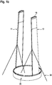
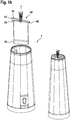
- FIGS. 1a to 1k The individual method steps of the method according to the invention for the assembly of tubular tubular tower segments 1, 2 from ten annular segment-shaped panels 10, 11, 12, 20, 21, 22 are explained. Both tubular tower segments 1, 2 are conically shaped.
- a first installation aid 30 is provided which is designed to receive the underside of the first tubular tower segment 1 or its annular segment-shaped panels 10, 11, 12.
- the first erection aid 30 is the foundation of the tubular tower construction to be erected by means of the tubular tower segment 1 as a tower for a wind energy plant.
- At the top of the erection aid 30 protrude threaded pins 31, to which the panels 10, 11, 12 can be attached.
- the panels 10, 11, 12 have for this purpose at their top and bottom for a corresponding connection in each case horizontally upright connecting flanges 13, 14.
- vertical flanges 15 are provided on the two remaining edges of the panels 10, 11, 12, via which two adjacent panels 10, 11, 12 of the tubular tower segment 1 can be connected to one another.
- the panels 10, 11, 12 are made of sheet steel, wherein the vertical flanges 15 are formed by folding the steel sheet, the connecting flanges 13, 14 by welded components.
- first a first panel 11 of the first tube tower segment 1 is placed on the positioning aid 30.
- the panel 11 on the threaded pins 31 of the structural aid 30 at the final desired position of the first panel 11 in the finished tube tower segment first put on and secured with nuts there.
- a bracing 32 may alternatively be provided.
- the first panel 11 has on its upper side an annular flange adapter segment 16 connected to the connecting flange 13 arranged there.
- the first panel 11 opposite the second panel 12 is placed on the positioning aid 30 and screwed there. Also, the second panel 12 can - if necessary - be secured by a brace 32 in position.
- the second panel 12 also has an annular flange adapter segment 16 on its upper side.
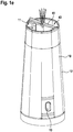
- the upper sides of the first and second panels 11, 12 are connected to one another via a mounting bracket 41 such that the two panels 11, 12 sufficiently support each other so that the bracing 32 (see. FIGS. 1a . 1b ) is no longer necessary and can be removed.
- the mounting bracket 41 is part of a mounting aid 40 and connected via the Ringflanschadaptersegmente 16 to the connecting flanges 13 on the upper sides of the first and second panels 11, 12 fixed thereto.
- the mounting bracket 41 has a pair of connection points 42, wherein in each case a connection point 42 in the region of one end of the mounting bracket is arranged (see also detail in FIG FIG. 2 ). Due to the defined connection points 42 it is ensured that the two panels 11, 12 are in the desired position for the further assembly of the tubular tower segment 1 to each other.
- actuating arms 44 are adjustable in length, in order to compensate for any manufacturing tolerances can.
- the number of actuating arms 44 corresponds to the number of further panels 10, namely eight.
- a cross member 45 is rotatably mounted about a vertical axis, wherein the length of the cross member 45 is smaller than the distance of the two connection points 42 of the mounting bracket 41.
- a working platform 46 is arranged vertically is movable.
- the platform 46 is according to the FIGS. 4a-c formed, from which it is immediately apparent that the platform 46 is designed to be extendable in its longitudinal direction. This extendability has the advantage that the vertical flanges 17 of the panels 10, 11, 12 can be easily reached from the working platform 46 at any height of the conically shaped tubular tower segment 1. In retracted state ( FIG. 4a ) However, the length of the platform 46 is smaller than the distance between the two connection points 42 of the mounting bracket 41st
- each newly established panel 10 can first over an adjusting arm 44 connected to the mounting bracket 41 (see Figure 2a) and, if necessary, with the aid of their length adjustability are aligned so that the holes provided for the screw in the vertical flanges 17 are aligned.
- the screw itself can be made from the work platform 46, which depart to the vertical flanges 17 in their height and, if necessary, can be extended lengthwise to the vertical flanges 17 to achieve good over its entire length can.
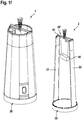
- the ring flange adapter segments 16 already present on the upper side of the panels 10, 11 are supplemented by further annular flange adapter segments 16 'to form a complete annular flange adapter (cf. FIG. 2b ), on which a further tube tower segment 2 can be fastened.
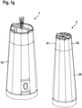
- the second tubular tower segment 2 is mounted substantially analogously to the first tubular tower segment 1. Instead of mounting directly on a foundation as Aufstell Anlagen 30, however, the installation is carried out on a separate mounting template as Aufstell Anlagen 35. Alternatively, the second tube tower segment 2 can be mounted directly on the already built on the foundation first tubular tower segment 1.
- a mounting aid 40 'to each other, between the panels 21, 22 and mounting bracket 41 but no Ringflanschadaptersegmente are provided ( FIG. 1f ).
- the mounting aid 40 ' is formed analogous to the mounting aid 40 for the first tubular tower segment 1 and adapted only to the different dimensions of the second tubular tower segment 2. Incidentally, reference is made to the above remarks on the assembly aid 40.
- the assembly of the further panels 20 of the second tubular tower segment 2 also runs analogously to the assembly of the further panels 10 (FIG. Figure 1g ), which is why reference is made here to the above explanations.
- the mounting aid 40 for the first tube tower segment 1 is removed. Since the length both the traverse 45 and the working platform 46 at least in the retracted state is less than the distance between the two connection points 42 on mounting bracket 41, the mounting aid 40 can be removed together with the working platform 46 upwards from the first tubular tower segment 1.
- the second tube tower segment 2 can be lifted as a whole from the mounting template or installation aid 35 and placed on the first tube tower segment 1 and screwed with this and the arranged at the top of the first tubular tower segment 1 Ringflanschadapter and secured (see FIG. 1i ).
- the second tube tower segment 2 can be raised via the assembly aid 40, ie a crane provided for this purpose engages the assembly aid 40 and not directly on the tube tower segment 2.
- an adapter module 50 is attached (see Figure 1k ), on which further tubular tower segments (not shown) can be arranged, wherein these further tubular tower segments can in particular be tubular components of prefabricated tubular tower segments with a maximum diameter of 4.5 m.
- the first tubular tower segment 1 has a lower diameter of 9.6 m and an upper diameter of 7.1 m.
- the second tube tower segment 2 has a corresponding lower diameter, and an upper diameter of 4.6 m.
- the adapter module 50 further reduces this diameter to 4.5 m.
- the height of the tube tower segments 1, 2 is in the illustrated embodiment, each 20 m.
- the individual panels 10, 11, 12, 20, 21, 22 are made of sheet steel with a thickness of 45 mm.
- FIGS. 3a . b an alternative embodiment of an assembly aid 40 "according to the invention is shown.
- the mounting aid 40 "has as well as the mounting aids 40, 40 'from Figures 1a-k and 2a, b a mounting bracket 41 with a pair of connection points 42 on. Located centrally between the connection points 42 is the central region 43 of the mounting bracket 41, on which pivotable and length-adjustable actuating arms 44 are arranged.
- a traverse 45 (see. Figures 1a-k and 2a, b ) has the mounting aid 40 "according to FIGS. 3a . b However, a arranged around the central region 43 of the mounting bracket 41 circular path 47. The diameter of the circular path 47 is smaller than the distance between the two connection points 42. The assembly aid 40 "can thus continue to be removed upward from a finished with their help tube tower segment 1, 2. At the same time, the circular path 47 in addition to the actuating arms 44 as additional alignment aid for the panels 10, 11, 12, 20, 21, 22 are used in the form of a revolving support circle.
- a working platform 48 is further arranged, which is movable both along the circular path 47 and in the vertical direction. Furthermore, the working platform 48 in the radial direction to the axis of the circular path or to the tube tower axis extendable such that even with conically shaped tube tower segments 1, 2, the connecting portions of two adjacent panels 10, 11, 12, 20, 21, 22 over the entire height of the tubular tower segment 1, 2 can be achieved well.
Landscapes
- Engineering & Computer Science (AREA)
- Architecture (AREA)
- Chemical & Material Sciences (AREA)
- Life Sciences & Earth Sciences (AREA)
- Mechanical Engineering (AREA)
- Combustion & Propulsion (AREA)
- Sustainable Energy (AREA)
- General Engineering & Computer Science (AREA)
- Sustainable Development (AREA)
- Civil Engineering (AREA)
- Structural Engineering (AREA)
- Materials Engineering (AREA)
- Wood Science & Technology (AREA)
- Wind Motors (AREA)
- Conveying And Assembling Of Building Elements In Situ (AREA)
Priority Applications (1)
| Application Number | Priority Date | Filing Date | Title |
|---|---|---|---|
| PL17156622T PL3208404T3 (pl) | 2016-02-19 | 2017-02-17 | Sposób i urządzenie do montażu segmentów wieży rurowej |
Applications Claiming Priority (1)
| Application Number | Priority Date | Filing Date | Title |
|---|---|---|---|
| DE102016002372.4A DE102016002372A1 (de) | 2016-02-19 | 2016-02-19 | Verfahren zur Montage eines Rohrturmsegments |
Publications (2)
| Publication Number | Publication Date |
|---|---|
| EP3208404A1 EP3208404A1 (de) | 2017-08-23 |
| EP3208404B1 true EP3208404B1 (de) | 2019-11-27 |
Family
ID=58057017
Family Applications (1)
| Application Number | Title | Priority Date | Filing Date |
|---|---|---|---|
| EP17156622.7A Active EP3208404B1 (de) | 2016-02-19 | 2017-02-17 | Verfahren und vorrichtung zur montage eines rohrturmsegments |
Country Status (6)
| Country | Link |
|---|---|
| EP (1) | EP3208404B1 (pl) |
| DE (1) | DE102016002372A1 (pl) |
| DK (1) | DK3208404T3 (pl) |
| ES (1) | ES2774522T3 (pl) |
| PL (1) | PL3208404T3 (pl) |
| PT (1) | PT3208404T (pl) |
Cited By (1)
| Publication number | Priority date | Publication date | Assignee | Title |
|---|---|---|---|---|
| WO2023274480A1 (en) * | 2021-06-30 | 2023-01-05 | Vestas Wind Systems A/S | A segmented wind turbine tower section and method of assembling same |
Families Citing this family (4)
| Publication number | Priority date | Publication date | Assignee | Title |
|---|---|---|---|---|
| DE102017125716A1 (de) * | 2017-11-03 | 2019-05-09 | Eno Energy Systems Gmbh | Verfahren zum Errichten eines Turms mit einer mehrteiligen Turmsektion und Teilsektion einer mehrteiligen Turmsektion eines Turms |
| CN108843518B (zh) * | 2018-08-23 | 2023-11-24 | 三一重能股份有限公司 | 风力发电机组及塔筒片式构件组对装置 |
| CN110905738B (zh) * | 2019-12-23 | 2025-05-02 | 苏州天顺新能源科技有限公司 | 一种用于处理大直径风塔表面凹陷的移动式工装 |
| CN111946555B (zh) * | 2020-07-17 | 2022-03-04 | 中国电建集团华东勘测设计研究院有限公司 | 一种装配式混凝土塔筒管片拼装平台及拼装方法 |
Family Cites Families (6)
| Publication number | Priority date | Publication date | Assignee | Title |
|---|---|---|---|---|
| EP1606514B1 (en) * | 2003-03-19 | 2007-11-07 | Vestas Wind System A/S | Method of constructing large towers for wind turbines |
| ES2326010B2 (es) * | 2006-08-16 | 2011-02-18 | Inneo21, S.L. | Estructura y procedimiento de montaje de torres de hormigon para turbinas eolicas. |
| ES2559211T3 (es) | 2010-07-13 | 2016-02-11 | Siemens Aktiengesellschaft | Plataforma de ensamblaje para el ensamblaje de una torre de turbina eólica o secciones de torre de turbina eólica |
| ES2435211B2 (es) * | 2012-05-18 | 2014-12-12 | Structural Research, S.L. | Grúa telescópica autotrepante y procedimiento de montaje de torres prefabricadas de hormigón |
| ES2438626B1 (es) * | 2012-10-01 | 2014-09-10 | Gestamp Hybrid Towers, S.L. | Estructura de soporte para aerogeneradores y molde para obtener tales estructuras |
| ES2538734B1 (es) * | 2013-12-20 | 2016-05-10 | Acciona Windpower, S.A. | Procedimiento de montaje de torres de hormigón de sección troncocónica y torre de hormigón montada con dicho procedimiento |
-
2016
- 2016-02-19 DE DE102016002372.4A patent/DE102016002372A1/de not_active Withdrawn
-
2017
- 2017-02-17 EP EP17156622.7A patent/EP3208404B1/de active Active
- 2017-02-17 PT PT171566227T patent/PT3208404T/pt unknown
- 2017-02-17 DK DK17156622.7T patent/DK3208404T3/da active
- 2017-02-17 PL PL17156622T patent/PL3208404T3/pl unknown
- 2017-02-17 ES ES17156622T patent/ES2774522T3/es active Active
Non-Patent Citations (1)
| Title |
|---|
| None * |
Cited By (1)
| Publication number | Priority date | Publication date | Assignee | Title |
|---|---|---|---|---|
| WO2023274480A1 (en) * | 2021-06-30 | 2023-01-05 | Vestas Wind Systems A/S | A segmented wind turbine tower section and method of assembling same |
Also Published As
| Publication number | Publication date |
|---|---|
| ES2774522T3 (es) | 2020-07-21 |
| EP3208404A1 (de) | 2017-08-23 |
| DK3208404T3 (da) | 2020-03-09 |
| PL3208404T3 (pl) | 2020-07-13 |
| DE102016002372A1 (de) | 2017-08-24 |
| PT3208404T (pt) | 2020-03-05 |
Similar Documents
| Publication | Publication Date | Title |
|---|---|---|
| EP3077670B1 (de) | Übergangskörper zwischen turmabschnitten einer windkraftanlage und turm einer windkraftanlage umfassend einen übergangskörper | |
| EP2877654B1 (de) | Modularer turm einer windkraftanlage | |
| EP3208404B1 (de) | Verfahren und vorrichtung zur montage eines rohrturmsegments | |
| EP2932095B1 (de) | Übergangskörper zur anordnung zwischen unterschiedlich ausgeführten abschnitten eines windkraftanlagenturms und windkraftanlagenturm mit einem solchen übergangskörper | |
| EP3208405B1 (de) | Vorrichtung und verfahren zur errichtung von turmartigen bauwerken aus fertigteilelementen | |
| EP3042011B1 (de) | Verfahren zur montage von turmeinbauten | |
| DE112019007295B4 (de) | Übergangsstück für einen windturbinenturm | |
| EP3230539B1 (de) | Verfahren zum errichten eines rohrturmbauwerks und rohrturmbauwerk | |
| EP3701107A1 (de) | Ringförmige konsole zum externen spannen eines turmsegments, externes spannsystem eines hybridturms, turmabschnitt eines hybridturms, hybridturm, windenergieanlage und montageverfahren eines externen spannsystems für einen hybridturm | |
| WO2012167774A2 (de) | Ständer für pv-module | |
| DE102017120487A1 (de) | Turm einer Windenergieanlage und Verfahren zum Herstellen eines Sektionssegments für einen solchen Turm | |
| DE102015115645A1 (de) | Verfahren zur Herstellung und zum Errichten eines Rohrturmbauwerks | |
| EP4063588B1 (de) | Verbindungsbauteil | |
| EP3445971B1 (de) | Übergangskörper für einen turm einer windkraftanlage, turm mit diesen sowie verfahren zu dessen errichtung | |
| EP2692967A2 (de) | Verfahren zum Errichten eines Turmes aus Stahl einer Windenergieanlage und Turm aus Stahl für eine Windenergieanlage | |
| DE102013221681B4 (de) | Hybridturm einer Windturbine | |
| EP3056611B1 (de) | Kopplungsvorrichtung zum verbinden einer tragstruktur mit einem fundament im meeresboden | |
| DE10308239A1 (de) | Verfahren und Vorrichtung zur Errichtung einer Windenergieanlage | |
| WO2024047070A1 (de) | Verfahren und kran zum aufbauen eines turms | |
| EP3447005B1 (de) | System und verfahren zum handhaben, lagern und transportieren von turmsegmenten | |
| EP3252305B1 (de) | Vorrichtung zum errichten einer windenergieanlage sowie verwendung der vorrichtung | |
| DE102011001919A1 (de) | Ankeranordnung, Verfahren zu deren Montage und Verfahren zur Herstellung eines Fundaments mit einer Ankeranordnung | |
| EP3543197B1 (de) | Vorrichtung zum anbringen eines leiterteils eines kranführeraufzugs an einem kranmasten | |
| WO2017045867A1 (de) | Türkonstruktion für ein rohrturmbauwerk | |
| EP3839172A1 (de) | Geländerholm zur montage eines vorlaufenden geländers, vorlaufendes geländer zur temporären fallsicherung einer neu zu erstellenden gerüstetage, gerüst für bau-, reparatur- und/oder montagearbeiten und verfahren zum aufbau eines gerüsts |
Legal Events
| Date | Code | Title | Description |
|---|---|---|---|
| PUAI | Public reference made under article 153(3) epc to a published international application that has entered the european phase |
Free format text: ORIGINAL CODE: 0009012 |
|
| STAA | Information on the status of an ep patent application or granted ep patent |
Free format text: STATUS: THE APPLICATION HAS BEEN PUBLISHED |
|
| AK | Designated contracting states |
Kind code of ref document: A1 Designated state(s): AL AT BE BG CH CY CZ DE DK EE ES FI FR GB GR HR HU IE IS IT LI LT LU LV MC MK MT NL NO PL PT RO RS SE SI SK SM TR |
|
| AX | Request for extension of the european patent |
Extension state: BA ME |
|
| STAA | Information on the status of an ep patent application or granted ep patent |
Free format text: STATUS: REQUEST FOR EXAMINATION WAS MADE |
|
| 17P | Request for examination filed |
Effective date: 20180122 |
|
| RBV | Designated contracting states (corrected) |
Designated state(s): AL AT BE BG CH CY CZ DE DK EE ES FI FR GB GR HR HU IE IS IT LI LT LU LV MC MK MT NL NO PL PT RO RS SE SI SK SM TR |
|
| GRAP | Despatch of communication of intention to grant a patent |
Free format text: ORIGINAL CODE: EPIDOSNIGR1 |
|
| STAA | Information on the status of an ep patent application or granted ep patent |
Free format text: STATUS: GRANT OF PATENT IS INTENDED |
|
| RIC1 | Information provided on ipc code assigned before grant |
Ipc: E04H 12/24 20060101ALI20190307BHEP Ipc: F03D 13/10 20160101ALI20190307BHEP Ipc: F03D 13/20 20160101ALI20190307BHEP Ipc: E04H 12/34 20060101ALI20190307BHEP Ipc: E04H 12/08 20060101AFI20190307BHEP |
|
| INTG | Intention to grant announced |
Effective date: 20190327 |
|
| GRAS | Grant fee paid |
Free format text: ORIGINAL CODE: EPIDOSNIGR3 |
|
| GRAA | (expected) grant |
Free format text: ORIGINAL CODE: 0009210 |
|
| STAA | Information on the status of an ep patent application or granted ep patent |
Free format text: STATUS: THE PATENT HAS BEEN GRANTED |
|
| AK | Designated contracting states |
Kind code of ref document: B1 Designated state(s): AL AT BE BG CH CY CZ DE DK EE ES FI FR GB GR HR HU IE IS IT LI LT LU LV MC MK MT NL NO PL PT RO RS SE SI SK SM TR |
|
| REG | Reference to a national code |
Ref country code: GB Ref legal event code: FG4D Free format text: NOT ENGLISH |
|
| REG | Reference to a national code |
Ref country code: CH Ref legal event code: EP |
|
| REG | Reference to a national code |
Ref country code: AT Ref legal event code: REF Ref document number: 1206820 Country of ref document: AT Kind code of ref document: T Effective date: 20191215 |
|
| REG | Reference to a national code |
Ref country code: DE Ref legal event code: R096 Ref document number: 502017002957 Country of ref document: DE |
|
| REG | Reference to a national code |
Ref country code: IE Ref legal event code: FG4D Free format text: LANGUAGE OF EP DOCUMENT: GERMAN |
|
| REG | Reference to a national code |
Ref country code: RO Ref legal event code: EPE |
|
| REG | Reference to a national code |
Ref country code: PT Ref legal event code: SC4A Ref document number: 3208404 Country of ref document: PT Date of ref document: 20200305 Kind code of ref document: T Free format text: AVAILABILITY OF NATIONAL TRANSLATION Effective date: 20200227 |
|
| REG | Reference to a national code |
Ref country code: DK Ref legal event code: T3 Effective date: 20200302 |
|
| REG | Reference to a national code |
Ref country code: FI Ref legal event code: FGE |
|
| REG | Reference to a national code |
Ref country code: SE Ref legal event code: TRGR |
|
| REG | Reference to a national code |
Ref country code: NL Ref legal event code: MP Effective date: 20191127 |
|
| REG | Reference to a national code |
Ref country code: LT Ref legal event code: MG4D |
|
| PG25 | Lapsed in a contracting state [announced via postgrant information from national office to epo] |
Ref country code: LV Free format text: LAPSE BECAUSE OF FAILURE TO SUBMIT A TRANSLATION OF THE DESCRIPTION OR TO PAY THE FEE WITHIN THE PRESCRIBED TIME-LIMIT Effective date: 20191127 Ref country code: NL Free format text: LAPSE BECAUSE OF FAILURE TO SUBMIT A TRANSLATION OF THE DESCRIPTION OR TO PAY THE FEE WITHIN THE PRESCRIBED TIME-LIMIT Effective date: 20191127 Ref country code: LT Free format text: LAPSE BECAUSE OF FAILURE TO SUBMIT A TRANSLATION OF THE DESCRIPTION OR TO PAY THE FEE WITHIN THE PRESCRIBED TIME-LIMIT Effective date: 20191127 Ref country code: NO Free format text: LAPSE BECAUSE OF FAILURE TO SUBMIT A TRANSLATION OF THE DESCRIPTION OR TO PAY THE FEE WITHIN THE PRESCRIBED TIME-LIMIT Effective date: 20200227 Ref country code: BG Free format text: LAPSE BECAUSE OF FAILURE TO SUBMIT A TRANSLATION OF THE DESCRIPTION OR TO PAY THE FEE WITHIN THE PRESCRIBED TIME-LIMIT Effective date: 20200227 |
|
| REG | Reference to a national code |
Ref country code: GR Ref legal event code: EP Ref document number: 20200400580 Country of ref document: GR Effective date: 20200511 |
|
| PG25 | Lapsed in a contracting state [announced via postgrant information from national office to epo] |
Ref country code: HR Free format text: LAPSE BECAUSE OF FAILURE TO SUBMIT A TRANSLATION OF THE DESCRIPTION OR TO PAY THE FEE WITHIN THE PRESCRIBED TIME-LIMIT Effective date: 20191127 Ref country code: RS Free format text: LAPSE BECAUSE OF FAILURE TO SUBMIT A TRANSLATION OF THE DESCRIPTION OR TO PAY THE FEE WITHIN THE PRESCRIBED TIME-LIMIT Effective date: 20191127 Ref country code: IS Free format text: LAPSE BECAUSE OF FAILURE TO SUBMIT A TRANSLATION OF THE DESCRIPTION OR TO PAY THE FEE WITHIN THE PRESCRIBED TIME-LIMIT Effective date: 20200327 |
|
| PG25 | Lapsed in a contracting state [announced via postgrant information from national office to epo] |
Ref country code: AL Free format text: LAPSE BECAUSE OF FAILURE TO SUBMIT A TRANSLATION OF THE DESCRIPTION OR TO PAY THE FEE WITHIN THE PRESCRIBED TIME-LIMIT Effective date: 20191127 |
|
| REG | Reference to a national code |
Ref country code: ES Ref legal event code: FG2A Ref document number: 2774522 Country of ref document: ES Kind code of ref document: T3 Effective date: 20200721 |
|
| PG25 | Lapsed in a contracting state [announced via postgrant information from national office to epo] |
Ref country code: CZ Free format text: LAPSE BECAUSE OF FAILURE TO SUBMIT A TRANSLATION OF THE DESCRIPTION OR TO PAY THE FEE WITHIN THE PRESCRIBED TIME-LIMIT Effective date: 20191127 Ref country code: EE Free format text: LAPSE BECAUSE OF FAILURE TO SUBMIT A TRANSLATION OF THE DESCRIPTION OR TO PAY THE FEE WITHIN THE PRESCRIBED TIME-LIMIT Effective date: 20191127 |
|
| REG | Reference to a national code |
Ref country code: DE Ref legal event code: R097 Ref document number: 502017002957 Country of ref document: DE |
|
| PG25 | Lapsed in a contracting state [announced via postgrant information from national office to epo] |
Ref country code: SK Free format text: LAPSE BECAUSE OF FAILURE TO SUBMIT A TRANSLATION OF THE DESCRIPTION OR TO PAY THE FEE WITHIN THE PRESCRIBED TIME-LIMIT Effective date: 20191127 Ref country code: SM Free format text: LAPSE BECAUSE OF FAILURE TO SUBMIT A TRANSLATION OF THE DESCRIPTION OR TO PAY THE FEE WITHIN THE PRESCRIBED TIME-LIMIT Effective date: 20191127 |
|
| REG | Reference to a national code |
Ref country code: CH Ref legal event code: PL |
|
| PLBE | No opposition filed within time limit |
Free format text: ORIGINAL CODE: 0009261 |
|
| STAA | Information on the status of an ep patent application or granted ep patent |
Free format text: STATUS: NO OPPOSITION FILED WITHIN TIME LIMIT |
|
| REG | Reference to a national code |
Ref country code: BE Ref legal event code: MM Effective date: 20200229 |
|
| PG25 | Lapsed in a contracting state [announced via postgrant information from national office to epo] |
Ref country code: LU Free format text: LAPSE BECAUSE OF NON-PAYMENT OF DUE FEES Effective date: 20200217 Ref country code: MC Free format text: LAPSE BECAUSE OF FAILURE TO SUBMIT A TRANSLATION OF THE DESCRIPTION OR TO PAY THE FEE WITHIN THE PRESCRIBED TIME-LIMIT Effective date: 20191127 |
|
| 26N | No opposition filed |
Effective date: 20200828 |
|
| PG25 | Lapsed in a contracting state [announced via postgrant information from national office to epo] |
Ref country code: SI Free format text: LAPSE BECAUSE OF FAILURE TO SUBMIT A TRANSLATION OF THE DESCRIPTION OR TO PAY THE FEE WITHIN THE PRESCRIBED TIME-LIMIT Effective date: 20191127 Ref country code: CH Free format text: LAPSE BECAUSE OF NON-PAYMENT OF DUE FEES Effective date: 20200229 Ref country code: LI Free format text: LAPSE BECAUSE OF NON-PAYMENT OF DUE FEES Effective date: 20200229 |
|
| PG25 | Lapsed in a contracting state [announced via postgrant information from national office to epo] |
Ref country code: IT Free format text: LAPSE BECAUSE OF FAILURE TO SUBMIT A TRANSLATION OF THE DESCRIPTION OR TO PAY THE FEE WITHIN THE PRESCRIBED TIME-LIMIT Effective date: 20191127 |
|
| PG25 | Lapsed in a contracting state [announced via postgrant information from national office to epo] |
Ref country code: BE Free format text: LAPSE BECAUSE OF NON-PAYMENT OF DUE FEES Effective date: 20200229 |
|
| PG25 | Lapsed in a contracting state [announced via postgrant information from national office to epo] |
Ref country code: MT Free format text: LAPSE BECAUSE OF FAILURE TO SUBMIT A TRANSLATION OF THE DESCRIPTION OR TO PAY THE FEE WITHIN THE PRESCRIBED TIME-LIMIT Effective date: 20191127 Ref country code: CY Free format text: LAPSE BECAUSE OF FAILURE TO SUBMIT A TRANSLATION OF THE DESCRIPTION OR TO PAY THE FEE WITHIN THE PRESCRIBED TIME-LIMIT Effective date: 20191127 |
|
| REG | Reference to a national code |
Ref country code: DE Ref legal event code: R081 Ref document number: 502017002957 Country of ref document: DE Owner name: SIEMENS GAMESA RENEWABLE ENERGY SERVICE GMBH, DE Free format text: FORMER OWNERS: SENVION GMBH, 22297 HAMBURG, DE; SIAG INDUSTRIE GMBH, 04347 LEIPZIG, DE Ref country code: DE Ref legal event code: R081 Ref document number: 502017002957 Country of ref document: DE Owner name: SIAG INDUSTRIE GMBH, DE Free format text: FORMER OWNERS: SENVION GMBH, 22297 HAMBURG, DE; SIAG INDUSTRIE GMBH, 04347 LEIPZIG, DE |
|
| PG25 | Lapsed in a contracting state [announced via postgrant information from national office to epo] |
Ref country code: MK Free format text: LAPSE BECAUSE OF FAILURE TO SUBMIT A TRANSLATION OF THE DESCRIPTION OR TO PAY THE FEE WITHIN THE PRESCRIBED TIME-LIMIT Effective date: 20191127 |
|
| REG | Reference to a national code |
Ref country code: AT Ref legal event code: MM01 Ref document number: 1206820 Country of ref document: AT Kind code of ref document: T Effective date: 20220217 |
|
| PG25 | Lapsed in a contracting state [announced via postgrant information from national office to epo] |
Ref country code: AT Free format text: LAPSE BECAUSE OF NON-PAYMENT OF DUE FEES Effective date: 20220217 |
|
| REG | Reference to a national code |
Ref country code: GB Ref legal event code: 732E Free format text: REGISTERED BETWEEN 20231116 AND 20231122 |
|
| PGFP | Annual fee paid to national office [announced via postgrant information from national office to epo] |
Ref country code: FR Payment date: 20240216 Year of fee payment: 8 |
|
| PG25 | Lapsed in a contracting state [announced via postgrant information from national office to epo] |
Ref country code: RO Free format text: LAPSE BECAUSE OF NON-PAYMENT OF DUE FEES Effective date: 20240217 |
|
| PGFP | Annual fee paid to national office [announced via postgrant information from national office to epo] |
Ref country code: SE Payment date: 20250321 Year of fee payment: 9 |
|
| PGFP | Annual fee paid to national office [announced via postgrant information from national office to epo] |
Ref country code: PT Payment date: 20250320 Year of fee payment: 9 Ref country code: DE Payment date: 20250226 Year of fee payment: 9 |
|
| PG2D | Information on lapse in contracting state deleted |
Ref country code: RO |
|
| PGFP | Annual fee paid to national office [announced via postgrant information from national office to epo] |
Ref country code: DK Payment date: 20250224 Year of fee payment: 9 Ref country code: FI Payment date: 20250324 Year of fee payment: 9 Ref country code: RO Payment date: 20250324 Year of fee payment: 9 |
|
| PGFP | Annual fee paid to national office [announced via postgrant information from national office to epo] |
Ref country code: ES Payment date: 20250317 Year of fee payment: 9 |
|
| PGFP | Annual fee paid to national office [announced via postgrant information from national office to epo] |
Ref country code: IE Payment date: 20250319 Year of fee payment: 9 |
|
| PGFP | Annual fee paid to national office [announced via postgrant information from national office to epo] |
Ref country code: GR Payment date: 20250320 Year of fee payment: 9 |
|
| PGFP | Annual fee paid to national office [announced via postgrant information from national office to epo] |
Ref country code: PL Payment date: 20250319 Year of fee payment: 9 |
|
| PGFP | Annual fee paid to national office [announced via postgrant information from national office to epo] |
Ref country code: GB Payment date: 20250218 Year of fee payment: 9 |
|
| PGFP | Annual fee paid to national office [announced via postgrant information from national office to epo] |
Ref country code: TR Payment date: 20250321 Year of fee payment: 9 |
|
| REG | Reference to a national code |
Ref country code: ES Ref legal event code: PC2A Owner name: SIEMENS GAMESA RENEWABLE ENERGY SERVICE GMBH Effective date: 20250829 |
|
| PG25 | Lapsed in a contracting state [announced via postgrant information from national office to epo] |
Ref country code: FR Free format text: LAPSE BECAUSE OF NON-PAYMENT OF DUE FEES Effective date: 20250228 |