EP3252305B1 - Vorrichtung zum errichten einer windenergieanlage sowie verwendung der vorrichtung - Google Patents
Vorrichtung zum errichten einer windenergieanlage sowie verwendung der vorrichtung Download PDFInfo
- Publication number
- EP3252305B1 EP3252305B1 EP17174028.5A EP17174028A EP3252305B1 EP 3252305 B1 EP3252305 B1 EP 3252305B1 EP 17174028 A EP17174028 A EP 17174028A EP 3252305 B1 EP3252305 B1 EP 3252305B1
- Authority
- EP
- European Patent Office
- Prior art keywords
- tower
- nacelle
- tower segment
- wind turbine
- mounting
- Prior art date
- Legal status (The legal status is an assumption and is not a legal conclusion. Google has not performed a legal analysis and makes no representation as to the accuracy of the status listed.)
- Active
Links
Images


Classifications
-
- F—MECHANICAL ENGINEERING; LIGHTING; HEATING; WEAPONS; BLASTING
- F03—MACHINES OR ENGINES FOR LIQUIDS; WIND, SPRING, OR WEIGHT MOTORS; PRODUCING MECHANICAL POWER OR A REACTIVE PROPULSIVE THRUST, NOT OTHERWISE PROVIDED FOR
- F03D—WIND MOTORS
- F03D13/00—Assembly, mounting or commissioning of wind motors; Arrangements specially adapted for transporting wind motor components
- F03D13/10—Assembly of wind motors; Arrangements for erecting wind motors
-
- F—MECHANICAL ENGINEERING; LIGHTING; HEATING; WEAPONS; BLASTING
- F05—INDEXING SCHEMES RELATING TO ENGINES OR PUMPS IN VARIOUS SUBCLASSES OF CLASSES F01-F04
- F05B—INDEXING SCHEME RELATING TO WIND, SPRING, WEIGHT, INERTIA OR LIKE MOTORS, TO MACHINES OR ENGINES FOR LIQUIDS COVERED BY SUBCLASSES F03B, F03D AND F03G
- F05B2230/00—Manufacture
- F05B2230/60—Assembly methods
- F05B2230/61—Assembly methods using auxiliary equipment for lifting or holding
-
- F—MECHANICAL ENGINEERING; LIGHTING; HEATING; WEAPONS; BLASTING
- F05—INDEXING SCHEMES RELATING TO ENGINES OR PUMPS IN VARIOUS SUBCLASSES OF CLASSES F01-F04
- F05B—INDEXING SCHEME RELATING TO WIND, SPRING, WEIGHT, INERTIA OR LIKE MOTORS, TO MACHINES OR ENGINES FOR LIQUIDS COVERED BY SUBCLASSES F03B, F03D AND F03G
- F05B2260/00—Function
- F05B2260/02—Transport, e.g. specific adaptations or devices for conveyance
-
- F—MECHANICAL ENGINEERING; LIGHTING; HEATING; WEAPONS; BLASTING
- F05—INDEXING SCHEMES RELATING TO ENGINES OR PUMPS IN VARIOUS SUBCLASSES OF CLASSES F01-F04
- F05B—INDEXING SCHEME RELATING TO WIND, SPRING, WEIGHT, INERTIA OR LIKE MOTORS, TO MACHINES OR ENGINES FOR LIQUIDS COVERED BY SUBCLASSES F03B, F03D AND F03G
- F05B2260/00—Function
- F05B2260/83—Testing, e.g. methods, components or tools therefor
-
- Y—GENERAL TAGGING OF NEW TECHNOLOGICAL DEVELOPMENTS; GENERAL TAGGING OF CROSS-SECTIONAL TECHNOLOGIES SPANNING OVER SEVERAL SECTIONS OF THE IPC; TECHNICAL SUBJECTS COVERED BY FORMER USPC CROSS-REFERENCE ART COLLECTIONS [XRACs] AND DIGESTS
- Y02—TECHNOLOGIES OR APPLICATIONS FOR MITIGATION OR ADAPTATION AGAINST CLIMATE CHANGE
- Y02E—REDUCTION OF GREENHOUSE GAS [GHG] EMISSIONS, RELATED TO ENERGY GENERATION, TRANSMISSION OR DISTRIBUTION
- Y02E10/00—Energy generation through renewable energy sources
- Y02E10/70—Wind energy
- Y02E10/72—Wind turbines with rotation axis in wind direction
-
- Y—GENERAL TAGGING OF NEW TECHNOLOGICAL DEVELOPMENTS; GENERAL TAGGING OF CROSS-SECTIONAL TECHNOLOGIES SPANNING OVER SEVERAL SECTIONS OF THE IPC; TECHNICAL SUBJECTS COVERED BY FORMER USPC CROSS-REFERENCE ART COLLECTIONS [XRACs] AND DIGESTS
- Y02—TECHNOLOGIES OR APPLICATIONS FOR MITIGATION OR ADAPTATION AGAINST CLIMATE CHANGE
- Y02P—CLIMATE CHANGE MITIGATION TECHNOLOGIES IN THE PRODUCTION OR PROCESSING OF GOODS
- Y02P70/00—Climate change mitigation technologies in the production process for final industrial or consumer products
- Y02P70/50—Manufacturing or production processes characterised by the final manufactured product
Definitions
- the invention relates to a device for erecting a wind turbine and its uses.
- a wind turbine comprises a tower constructed on a foundation of several tower sections, at the upper end of which a gondola is rotatably arranged in the azimuth direction.
- a rotor drivable by the rotor is arranged with a substantially horizontal axis of rotation, which drives a generator arranged in the nacelle.
- the electrical power generated in this way can, if appropriate with the interposition of converters and / or transformers, be fed into a supply network.
- the tower is first constructed according to the prior art after creation of the foundation by gradually lifted the individual tower sections on the foundation or already mounted tower sections and fixed there.
- the tower is completed, either the nacelle is completely or a first part of the nacelle lifted onto the tower and rotatably mounted at the top for later azimuth orientation.
- the driveline is in the already mounted part of the nacelle lifted and aligned there and fixed. Only then is the gondola closed with a roof.
- the assembly of the rotor takes place.
- Two fundamentally different assembly methods are known. In one assembly method, the rotor hub is first rotatably attached to the nacelle, before subsequently the rotor blades are fastened individually to the already in position rotor hub. In the other assembly method, the rotor is preassembled on the ground, i. The rotor blades are already attached to the rotor hub, before the rotor is lifted as a whole to the height of the nacelle and fastened there.
- a disadvantage of this prior art is that virtually for the entire period of installation of a wind turbine, a main crane is needed whose hook height makes it possible to raise the components to be mounted on the tower top. Due to the size of the crane required, it can not be used elsewhere during assembly, when it is not mandatory, such as testing or commissioning individual components in the nacelle before the rotor is mounted. The same applies if the individual components are to be delivered to the place of installation in a timely manner to their respective assembly, but there are delays in the delivery.
- the invention has for its object to provide a comparison with the prior art improved device for building a wind turbine, as well as to use this device.
- the invention relates to a device for pre-assembly of the nacelle of a wind turbine on a top tower segment, wherein a receptacle for vertical attachment of a tower segment of the wind turbine is arranged on a base frame and wherein a base frame arranged receptacle for the rotor hub for the horizontal mounting of the wind turbine rotor is provided , which is arranged opposite the receptacle for the tower segment, that the installation of the wind turbine rotor is also possible with a tower segment arranged on the receptacle for the tower segment, wherein the tower segment arranged as a counterweight during assembly of the wind turbine rotor acts, the mounting device so folds - And / or telescoping is that it has outer dimensions of a maximum of 2.5 mx 2.75 mx 10 m in the folded state.
- the invention further relates to the use of a device according to the invention, wherein a top tower segment in a vertical position is arranged in the receptacle and wherein the nacelle is pre-assembled on the top tower segment, before the top tower segment is lifted onto the tower mounted on the top tower segment and fastened there.
- the nacelle By mounting the gondola already close to the ground on the topmost tower segment when constructing a wind energy plant according to the invention and then both components are lifted together on the tower which is already built up to a large extent from the remaining tower segments and fastened there, the nacelle can be preassembled top tower segment already carried out various installation and verification work near the ground, which would otherwise be carried out at high altitude.
- missing parts or defects on the nacelle can be detected at a time when the nacelle is still near the ground, so that the subsequent installation of missing parts or the repair of defects is often easier.
- the preassembly of the nacelle can be started so early before putting the nacelle together with the top tower segment that a time buffer for any delays in the pre-assembly of the nacelle is available and the schedule for the actual erection of the wind turbine with the placement of the nacelle is not endangered as one of the last steps.
- pre-assembly near the ground is less dependent on the weather than mounting the gondola at high altitudes.
- the pre-assembly can be made regardless of the construction of the tower of the other tower segments.
- no large crane is required for the actual pre-assembly.
- the topmost tower segment is essentially only to attach and connect the various lines and / or rail systems at the transition between the top tower segment and the underlying tower segment.
- Another (internal) expansion of the nacelle and the upper tower segment is usually no longer required. Rather, almost directly the rotor can be attached to the nacelle.
- the uppermost tower segment for the preassembly of the nacelle is in a vertical position.
- the topmost tower segment is thus in an orientation for the preassembly of the nacelle, in which it is also in the fully erected state of the wind turbine. Consequently, the nacelle is preassembled in a position in which it is also in the final state of the wind turbine.
- the preassembly of the nacelle on the uppermost tower segment includes the assembly of the driveline in the nacelle, the assembly and alignment of the generator shaft, the installation of barriers, the installation of driveline sensors, the installation of power cables in the nacelle, the installation of the cable loop in the nacelle area, the installation of the Azimutverstellantriebs and / or the installation of the nacelle lighting. All of the aforementioned assemblies can be easily carried out already during the pre-assembly of the nacelle on the top tower segment.
- the preassembly of the nacelle on the uppermost tower segment comprises the commissioning and / or testing of the nacelle control, the sensor system and / or the azimuth adjustment.
- the nacelle can be externally powered by the electrical power required for each test. If the gondola has an emergency generator, which is already mounted, but the required electrical power can also be provided by this.
- the uppermost tower segment preferably has a height of at least 10 m, more preferably at least 15 m.
- the pre-assembly is also connected to the nacelle components that protrude into the tower, such as. The cable loop, allows.
- the attachment of the uppermost tower segment to the partially assembled tower preferably includes the installation of tower bolts, ladder connectors and bus bar connectors.
- the rest of the (inner) expansion of the uppermost tower segment and / or the nacelle is, as already mentioned, preferably before the attachment of the uppermost tower segment on the partially assembled tower.
- the rotor After attachment of the uppermost tower segment on the partially assembled tower, the rotor is preferably rotatably attached to the nacelle of the wind turbine. Since in the inventive use of the device after the attachment of the The top tower segment on the partially assembled tower no or very few assembly work on the nacelle are required, the attachment of the rotor to the nacelle can be carried out immediately after or at a short time interval.
- the advantages of the invention are particularly apparent in the construction of several, preferably all wind turbines of a wind farm. Due to the proximity of the erected wind turbines of a wind farm, the cranes required for the construction of the tower and for the pre-assembly of the nacelle on the top tower segment - usually at least one large crane and a smaller crane - can be used very efficiently.
- the advantages arise in particular if five or more wind turbines, preferably eight or more wind turbines of a wind farm to be built at the same time.
- the mounting device comprises a receptacle arranged on the base frame for the rotor hub for the horizontal mounting of the wind turbine rotor, which is arranged opposite the receptacle for the tower segment that the installation of the wind turbine rotor is also possible in a tower segment arranged on the receptacle for the tower segment, wherein the thus arranged tower segment acts as a counterweight during assembly of the wind turbine rotor.
- the latter can be achieved by the two recordings are arranged in a horizontal direction spaced from each other.
- a tower segment arranged on the receptacle for a tower segment can protrude in particular between the rotor blades of a rotor which is completely mounted on the receptacle for the wind energy plant rotor, which immediately shows that the assembly of the wind turbine rotor also occurs Presence of a corresponding tower segment - even with possibly already mounted thereon gondola - is possible.
- the rotor hub with vertical orientation of the rotor hub axis is first attached to a suitable receptacle before the individual rotor blades are attached to it in succession. Since the rotor blades are mounted one after the other, the moments for the wind turbine rotor during assembly are affected by different moments resulting from the weight forces of the rotor blades, in particular before all the rotor blades are mounted. To compensate for these moments, it is known as a way to use counterweights.
- the receptacle for the tower segment on the base frame is arranged so that a tower segment arranged thereon - possibly with it already mounted gondola - serves as a counterweight. This offers the advantage that no separate counterweights need to be provided, which in particular reduces the overall transport costs for base frame ballast weights or the aids for setting up a wind energy plant.
- the receptacle for the rotor hub for the horizontal assembly of the wind turbine rotor comprises a rotating device with which the rotor hub fixed to the receptacle can be rotated about the rotor hub axis.
- a corresponding turning device makes it possible to rotate the partially assembled wind turbine rotor during assembly so that the moment acting on it by the mounting device can be compensated by the weight of a tower segment arranged on the receptacle for tower segments.
- the mounting device can be hinged and / or telescoped such that it has outer dimensions of not more than 2.5 m ⁇ 2.75 m ⁇ 10 m in the folded state, preferably that the outer dimensions are selected such that the mounting device is mounted in a 40-foot frame.
- Standard container more preferably loaded in a standard 20-foot container.
- the mounting device can be so merge to a transport volume, which allows easy transport without interference, especially on the road and / or by boat.
- the receptacle for the wind turbine rotor of the mounting device comprises at least one tower element of a tower system of a building crane, wherein the tower system is releasably secured to the base frame and the receptacle for the wind turbine rotor is arranged at the end remote from the base frame of the tower system.
- a suitable adapter device can be provided which can be connected on one side with the tower system and on the other side has a rotor flange for attachment of the rotor hub.
- Tower system of a building crane refers to the system for the construction of the tower of a mobile tower crane, in particular a top-rotating tower crane.
- Corresponding tower systems are offered by various manufacturers and include a base segment on which individual tower segments are arranged to ultimately form the tower of the crane at a desired height.
- the individual tower segments are designed and dimensioned so that they can be easily transported by truck to the desired location of the tower crane and include interfaces for connection to other segments.
- the transport of the mounting device according to the invention from one location to the next essentially limited to the base frame.
- the tower system can be provided locally, for example by local lenders of tower cranes with suitable tower systems. It can thus be avoided that a high transport volume and / or a high transport weight must be transported over some long distances.
- a tower system in mounting for the wind turbine rotor allows for mounting the rotor spaced from the ground.
- the tower system comprising at least one tower segment necessarily already has a certain height, mounted thereon a rotor of a wind turbine is spaced from the ground so that at least one passage through the rotor is regularly possible.
- the distance between the ground and the rotor can also be chosen so well that any desired clearance height, for example to ensure passage through vehicles or other equipment, is achieved. It can also be achieved to mount the rotor above so-called inventory obstacles, such as trees, so that they do not have to be removed, e.g. by precipitation.
- the mounting device allows the rotor mounting on a slope by the rotor is increased so that the directed to the slope leaves can be positioned horizontally.
- the tower element and / or the number of tower elements is preferably selected such that the minimum clearance height below a wind turbine rotor mounted on the receptacle is at least 4.5 m, preferably at least 8 m, more preferably at least 9.5 m.
- a plurality of tower elements arranged on top of each other can be provided in order to achieve the ultimately desired passage height.
- the maximum height of a wind turbine rotor mounted on the receptacle above the ground is 40 m, preferably 35 m, more preferably 25 m.
- FIG. 1 is an embodiment of a mounting device 1 with arranged thereon tower segment 10 with preassembled nacelle 20 of a wind turbine shown schematically, with tower segment 10 and gondola 20 are shown partially transparent.
- the mounting device 1 comprises a base frame 2 with height-adjustable feet 3 to compensate for uneven floors.
- the base frame 2 has at its top a receptacle 4, to which the uppermost tower segment 10 of the tower of a wind turbine is mounted in a vertical arrangement.
- the nacelle 20 is rotatably mounted, wherein for the assembly of the nacelle 20, first of the tower segment 10 directly rotatably connected part of the nacelle 20 has been mounted before subsequently the drive train 21 was inserted into the already mounted part of the nacelle 20.
- the generator shaft 22 was mounted and aligned.
- the barrier 23 toward Nabenniedergang various drive train sensors 24, the power cable 25 in the tower area, which are designed as a so-called cable loop, the nacelle lighting 26 and the supply lines 27 to Supplying the components of the nacelle 20 via the nacelle generator.
- the roof of the gondola 20 was put on.
- the uppermost tower segment 10 Since the installation of the nacelle 20 on the uppermost tower segment 10 is close to the ground - the uppermost tower segment 10 is arranged on the base frame 2 of the mounting device 1, which is on the ground - this is only a relatively small crane required. Unlike the required for the final construction of the wind turbine large crane can Pre-assembly of the nacelle 20 on the top tower segment 10 with a much smaller crane, in particular a mobile crane are performed.
- the nacelle 20 In addition to the installation of the nacelle 20 on the top tower segment 10 can further made a first commissioning of various components of the nacelle 20 and the control, the sensors and the azimuth of the nacelle 20 are tested so close to the ground that in case of failure, the repair also close to the ground and thus in particular can be carried out more cost-effectively than if it had to be carried out at a greater height with fully assembled tower of the wind turbine with arranged thereon gondola 20.
- FIG. 2 is the mounting device 1, as in FIG. 1 is shown, ie in particular with mounted on top tower segment 10 and nacelle 20, shown at the installation of a wind turbine.
- lowest tower segment 12 of the wind turbine is the crane footprint 31, on which a large crane 30 is placed.
- the other tower segments (not shown) of the tower of the wind turbine can successively on the already mounted tower segments, starting with the lowest tower segment 12 mount.
- the top tower segment 10 is lifted together with the mounted thereon gondola 20 on the tower and fixed there.
- the mounting device 1 is arranged in the operating radius of the large crane 30, so that the top tower segment 10 arranged thereon can be easily lifted by the large crane 30 with preassembled nacelle 20.
- top tower segment 10 is raised to the already mounted tower, the segment only has to be connected to the underlying tower segment, in addition only the various line connections and / or connections of rail systems (such as a ladder, busbars or elevator guides), between the two Tower segments must be made. A further (internal) expansion of the tower and in particular the gondola 20 is not required.
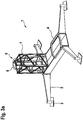
- FIG. 3a two variants of an embodiment of a mounting device 1 according to the invention are shown.
- the mounting device 1 again comprises a base frame 2 with height-adjustable feet 3 to compensate for uneven floors.
- the base frame 2 also has a receptacle 4 on its upper side, to which the uppermost tower segment 10 of the tower of a wind energy plant can be fastened in a vertical arrangement.
- the mounting device 1 still has a receptacle 5 for the horizontal mounting of a wind turbine rotor 13.
- the recording 5 is to attach the Rotor hub 14 arranged thereon so that the assembly of the wind turbine rotor 13 parallel to the pre-assembly of the nacelle 20 on the top tower segment 10, which takes place on the corresponding receptacle 4, can be performed.
- the uppermost tower segment 10 can protrude through the rotor blades 15 of the rotor 13.
- the tower segment 10 mounted on the base frame, together with the gondola 20 already mounted thereon, serves as a counterweight for a partially mounted wind turbine rotor 13.
- the receptacle 5 for the rotor hub 14 of a wind turbine rotor 13 comprises a rotating device 6, with which the rotor hub 14 attached thereto can be rotated about its rotor hub axis.
- the receptacle 5 for the rotor hub 14 is arranged elevated relative to the receptacle 4 for the uppermost tower segment 10, wherein for the production of the distance between the base frame 2 and the actual receptacle 5 for the rotor hub 14 can be accessed on a tower element 7 of a tower system of a building crane ( See embodiment according to FIG. 3a ).
- a tower element 7 of a tower system of a building crane See embodiment according to FIG. 3a .
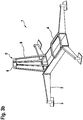
- the rotating device 6 is arranged on a special support frame 8, which is directly connected to the base frame.
- FIG. 3b A corresponding embodiment variant is in FIG. 3b shown.
- the tower element 7 is detachably attached to the base frame 2. If the tower element 7 is removed, the base frame 2 can be folded by flaps to a level with which it is in a standard 20-foot container can be transported (not shown).
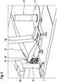
- FIG. 4 is the situation at the installation of a wind turbine with the mounting device 1 according to FIG. 3a shown.
- the mounting device 1 is arranged on the crane footprint 31, that both the preassembled top tower segment 10 with nacelle 20 and the rotor 13 of the large crane 30 can be easily raised.
- the passage height below the mounted on the receptacle 5 of the mounting device 1 rotor 13 is at least 8 m, the maximum height of the rotor 13 is well below 25 m. Due to the appropriate dimensions, on the one hand, the site traffic below the rotor can be done easily, while at the same time comparatively small cranes for the assembly of the rotor 13 can be used.
Description
- Die Erfindung betrifft eine Vorrichtung zum Errichten einer Windenergieanlage sowie deren Verwendungen.
- In einer aus dem Stand der Technik bekannten, weit verbreiteten Bauform umfasst eine Windenergieanlage ein auf einem Fundament aus mehreren Turmsektionen aufgebauten Turm, an dessen oberen Ende in Azimutrichtung drehbar eine Gondel angeordnet ist. An der Gondel ist ein vom Wind antreibbarer Rotor mit einer im Wesentlichen horizontalen Rotationsachse angeordnet, der einen in der Gondel angeordneten Generator antreibt. Die so erzeugte elektrische Leistung kann, ggf. unter Zwischenschaltung von Umrichtern und/oder Transformatoren, in ein Versorgungsnetz eingespeist werden.
- Bei der Errichtung entsprechender Windenergieanlagen wird gemäß dem Stand der Technik nach Erstellung des Fundaments zunächst der Turm errichtet, indem nach und nach die einzelnen Turmsektionen auf das Fundament bzw. bereits montierte Turmsektionen gehoben und dort befestigt werden. Ist der Turm fertiggestellt, wird entweder die Gondel komplett oder ein erster Teil der Gondel auf den Turm gehoben und an dessen Spitze zur späteren Azimutausrichtbarkeit drehbar befestigt. Anschließend wird der Triebstrang in den bereits montierten Teil der Gondel gehoben und dort ausgerichtet und befestigt. Erst dann wird die Gondel mit einem Dach verschlossen.
- Ist die Gondel vollständig auf dem Turm der Windenergieanlage montiert, erfolgt die Montage des Rotors. Dabei sind zwei grundsätzlich unterschiedliche Montageverfahren bekannt. Bei dem einen Montageverfahren wird zunächst die Rotornabe drehbar an der Gondel befestigt, bevor anschließend die Rotorblätter einzeln an der bereits in Position befindlichen Rotornabe befestigt werden. Bei dem anderen Montageverfahren wird der Rotor am Boden vormontiert, d.h. die Rotorblätter sind bereits an der Rotornabe befestigt, bevor der Rotor als Ganzes auf die Höhe der Gondel angehoben und dort befestigt wird.
- Nachteilig an diesem Stand der Technik ist, dass praktisch für den gesamten Zeitraum der Montage einer Windenergieanlage ein Hauptkran benötigt wird, dessen Hakenhöhe es ermöglicht, auch die an der Turmspitze zu montierenden Komponenten anzuheben. Aufgrund der Größe des erforderlichen Krans kann dieser auch zu Zeiten während der Montage, in denen er nicht zwingend gebraucht wird, wie bspw. des Tests oder der Inbetriebnahme einzelner Komponenten in der Gondel bevor der Rotor montiert wird, nicht anderweitig verwendet werden. Gleiches gilt auch, falls die einzelnen Komponenten erst zeitnah zu deren jeweiliger Montage am Aufstellort angeliefert werden sollen, es aber zu Verzögerungen bei der Anlieferung kommt.
- Im Stand der Technik finden sich weiterhin Vorrichtungen zur Errichtung von Windenergieanlagen, mit denen Windenergieanlage vollständig oder in Teilen vormoniert werden können. Die in Dokumenten
WO 03/093584 A1 US 2012/0131876 A1 ,KR 10-2014-0004282 EP 2 256 079 A1 gezeigten Vorrichtungen sind dabei vornehmlich für den Offshore-Bereich und somit für die Anordnung auf Schiffen oder anderen Schwimmkörpern konzipiert; entsprechende Vorrichtung für den Onshore-Bereich sind nicht gezeigt. - Der Erfindung liegt die Aufgabe zugrunde, eine gegenüber dem Stand der Technik verbesserte Vorrichtung zum Errichten einer Windenergieanlage, sowie eine Verwendung dieser Vorrichtung zu schaffen.
- Gelöst wird diese Aufgabe durch eine Vorrichtung gemäß dem Hauptanspruch sowie eine Verwendung gemäß Anspruch 5. Vorteilhafte Weiterbildungen sind Gegenstand der abhängigen Ansprüche.
- Demnach betrifft die Erfindung eine Vorrichtung zur Vormontage der Gondel einer Windenergieanlage auf einem obersten Turmsegment, wobei eine Aufnahme zur vertikalen Befestigung eines Turmsegments der Windenergieanlage an einem Grundrahmen angeordnet ist und wobei eine am Grundrahmen angeordnete Aufnahme für die Rotornabe für die horizontale Montage des Windenergieanlagenrotors vorgesehen ist, die derart gegenüber der Aufnahme für das Turmsegment angeordnet ist, dass die Montage des Windenergieanlagenrotors auch bei einem auf der Aufnahme für das Turmsegment angeordneten Turmsegment möglich ist, wobei das so angeordnete Turmsegment als Gegengewicht während der Montage des Windenergieanlagenrotors wirkt, wobei die Montagevorrichtung derart klapp- und/oder teleskopierbar ist, dass sie im zusammengelegten Zustand Außenabmaße von maximal 2,5 m x 2,75 m x 10 m aufweist.
- Die Erfindung betrifft weiterhin die Verwendung einer erfindungsgemäßen Vorrichtung, wobei ein oberstes Turmsegment in einer vertikalen Position in der Aufnahme angeordnet wird und wobei die Gondel an dem obersten Turmsegment vormontiert wird, bevor das oberste Turmsegment auf den bis auf das oberste Turmsegment montierten Turm gehoben und dort befestigt wird.
- Indem beim Errichten einer Windenergieanlage bei erfindungsgemäßer Verwendung der Vorrichtung die Gondel bodennah bereits auf dem obersten Turmsegment montiert und anschließend beide Komponenten gemeinsam auf dem aus den übrigen Turmsegmenten bereits zu weiten Teilen aufgebauten Turm gehoben und dort befestigt werden, können bei der Vormontage der Gondel auf dem obersten Turmsegment bereits diverse Installations- und Überprüfungsarbeiten in Bodennähe ausgeführt werden, die ansonsten in großer Höhe durchgeführt werden müssten. Insbesondere fehlende Teile oder Defekte an der Gondel können zu einem Zeitpunkt erkannt werden, in dem sich die Gondel noch in Bodennähe befindet, sodass der nachträgliche Einbau fehlender Teile oder das Beheben von Defekten häufig einfacher möglich ist. Auch kann die Vormontage der Gondel derart frühzeitig vor dem Aufsetzen der Gondel zusammen mit dem obersten Turmsegment begonnen werden, dass ein Zeitpuffer für evtl. Verzögerungen bei der Vormontage der Gondel zur Verfügung steht und der Zeitplan für die eigentlich Errichtung der Windenergieanlage mit dem Aufsetzen der Gondel als einem der letzten Schritte nicht gefährdet wird. Schlussendlich ist eine Vormontage in Bodennähe weniger wetterabhängig als eine Montage der Gondel in großer Höhe.
- Auch kann die Vormontage unabhängig von der Errichtung des Turms aus den übrigen Turmsegmenten erfolgen. Für die eigentliche Vormontage ist dabei insbesondere kein Großkran erforderlich. Vielmehr kann die Vormontage der Gondel auf dem obersten Turmsegment mit einem kleineren Kran, insbesondere einem Mobilkran, durchgeführt werden; ein Großkran ist erst erforderlich, um die Kombination aus oberstem Turmsegment und Gondel auf den ansonsten bereits errichteten Turm zu heben.
- Wenn das oberste Turmsegment zusammen mit der darauf vormontierten Gondel auf dem bereits errichteten Teil des Turms gehoben wird, ist das oberste Turmsegment im Wesentlichen nur zu befestigen und die diversen Leitungen und/oder Schienensysteme am Übergang zwischen obersten Turmsegment und darunterliegendem Turmsegment zu verbinden. Ein weiterer (Innen-)Ausbau der Gondel und des oberen Turmsegmentes ist in der Regel nicht mehr erforderlich. Vielmehr kann praktisch unmittelbar der Rotor an der Gondel befestigt werden.
- Erfindungsgemäß befindet sich das oberste Turmsegment für die Vormontage der Gondel in einer vertikalen Position. Das oberste Turmsegment befindet sich für die Vormontage der Gondel also in einer Ausrichtung, in der es sich auch im vollständig errichteten Zustand der Windenergieanlage befindet. Folglich wird auch die Gondel in einer Lage vormontiert, in der sie sich auch im Endzustand der Windenergieanlage befindet.
- Vorzugsweise umfasst die Vormontage der Gondel auf dem obersten Turmsegment die Montage des Triebstrangs in der Gondel, die Montage und Ausrichtung der Generatorwelle, die Montage von Absperrgittern, die Montage von Triebstrangsensoren, die Montage von Leistungskabeln in der Gondel, die Montage des Kabelloops im Gondelbereichs, die Montage des Azimutverstellantriebs und/oder die Montage der Gondelbeleuchtung. Sämtlich vorgenannten Montagen lassen sich ohne weiteres bereits während der Vormontage der Gondel auf dem obersten Turmsegment durchführen.
- Es ist weiter bevorzugt, wenn die Vormontage der Gondel auf dem obersten Turmsegment die Inbetriebnahme und/oder das Testen der Gondelsteuerung, der Sensorik und/oder der Azimutverstellung umfasst. Die Gondel kann mit der für die einzelnen Tests erforderlichen elektrischen Leistung von extern versorgt werden. Sofern die Gondel über ein Notstromaggregat verfügt, welches bereits montiert ist, kann die erforderliche elektrische Leistung aber auch von diesem bereitgestellt werden. Indem diverse Funktionen der Gondel bereits in Bodennähe getestet werden können, lassen sich evtl. festgestellte Fehler und Defekte vergleichsweise einfach beheben, insbesondere im Vergleich zu einer Fehlerdetektion erst nachdem die Gondel auf einen vollständig errichteten Turm einer Windenergieanlage befestigt wurde.
- Das oberste Turmsegment weist vorzugsweise eine Höhe von wenigstens 10 m, weiter vorzugsweise von wenigstens 15 m auf. Durch eine entsprechende Höhe wird die Vormontage auch von an der Gondel angebundenen Komponenten, die in den Turm hineinragen, wie bspw. dem Kabelloop, ermöglicht.
- Die Befestigung des obersten Turmsegments auf dem teilweise montierten Turm umfasst vorzugsweise die Montage von Turmschrauben, Leiterverbindern und Stromschienenverbindern. Der übrige (Innen-)Ausbau des obersten Turmsegments und/oder der Gondel erfolgt, wie bereits erwähnt, vorzugsweise vor der Befestigung des obersten Turmsegments auf dem teilweise montierten Turm.
- Nach der Befestigung des obersten Turmsegments auf dem teilweise montierten Turm wird bevorzugt der Rotor drehbar an der Gondel der Windenergieanlage befestigt. Da bei der erfindungsgemäßen Verwendung der Vorrichtung nach der Befestigung des obersten Turmsegments auf dem teilweise montierten Turm keine oder nur sehr wenige Montagearbeiten an der Gondel erforderlich sind, kann die Befestigung des Rotors an der Gondel unmittelbar anschließend oder in kurzem Zeitabstand erfolgen.
- Die Vorteile der Erfindung ergeben sich insbesondere bei der Errichtung mehrerer, vorzugsweise aller Windenergieanlagen eines Windparks. Aufgrund der räumlichen Nähe der aufzustellenden Windenergieanlagen eines Windparks können die für die Errichtung des Turms und für die Vormontage der Gondel auf dem obersten Turmsegment benötigten Kräne - in der Regel wenigstens ein Großkran und ein kleinerer Kran - besonders effizient eingesetzt werden. Die Vorteile ergeben sich insbesondere wenn fünf oder mehr Windenergieanlagen, vorzugsweise acht oder mehr Windenergieanlagen eines Windparks zeitgleich errichtet werden sollen.
- Die Montagevorrichtung weist erfindungsgemäß eine am Grundrahmen angeordnete Aufnahme für die Rotornabe für die horizontale Montage des Windenergieanlagenrotors auf, die derart gegenüber der Aufnahme für das Turmsegment angeordnet ist, dass die Montage des Windenergieanlagenrotors auch bei einem auf der Aufnahme für das Turmsegment angeordneten Turmsegment möglich ist, wobei das so angeordnete Turmsegment als Gegengewicht während der Montage des Windenergieanlagenrotors wirkt. Letzteres kann erreicht werden, indem die beiden Aufnahmen in horizontaler Richtung beabstandet voneinander angeordnet sind. Ein auf der Aufnahme für ein Turmsegment angeordnetes Turmsegment kann insbesondere zwischen den Rotorblättern eines auf der Aufnahme für den Windenergieanlagenrotor vollständig montierten Rotor hindurch ragen, womit unmittelbar ersichtlich ist, dass auch die Montage des Windenergieanlagenrotors bei Vorhandensein eines entsprechenden Turmsegments - auch bei evtl. bereits darauf montierter Gondel - möglich ist.
- Bei der Montage des Windenergieanlagenrotors in horizontaler Position wird zunächst die Rotornabe mit vertikaler Ausrichtung der Rotornabenachse an einer dafür geeigneten Aufnahme befestigt, bevor daran die einzelnen Rotorblätter nacheinander befestigt werden. Da die Rotorblätter nacheinander montiert werden, wirken auf die Aufnahme für den Windenergieanlagenrotor während der Montage verschiedene, aus den Gewichtskräften der Rotorblätter resultierende Momente, insbesondere bevor alle Rotorblätter montiert sind. Zum Ausgleich dieser Momente ist es als eine Möglichkeit bekannt, Gegengewichte zu verwenden. Erfindungsgemäß ist hierfür die Aufnahme für das Turmsegment am Grundrahmen so angeordnet, dass ein darauf angeordnetes Turmsegment - ggf. mit daran bereits montierter Gondel - als Gegengewicht dient. Dies bietet den Vorteil, dass keine gesonderten Gegengewichte bereitgestellt werden müssen, womit sich insbesondere der Transportaufwand für Grundrahmen-Ballastgewichte bzw. die Hilfsmittel zur Errichtung einer Windenergieanlage insgesamt reduzieren lässt.
- Es ist bevorzugt, wenn die Aufnahme für die Rotornabe für die horizontale Montage des Windenergieanlagenrotors eine Drehvorrichtung umfasst, mit der sich die an der Aufnahme befestigte Rotornabe um die Rotornabenachse drehen lässt. Eine entsprechende Drehvorrichtung ermöglicht es, den teilmontierten Windenergieanlagenrotor während der Montage so zu drehen, dass das durch ihn auf die Montagevorrichtung einwirkende Moment durch das Gewicht eines auf der Aufnahme für Turmsegmente angeordneten Turmsegments ausgeglichen werden kann.
- Die Montagevorrichtung ist erfindungsgemäß derart klapp- und/oder teleskopierbar, dass sie im zusammengelegten Zustand Außenabmaße von maximal 2,5 m x 2,75 m x 10 m aufweist, vorzugweise dass die Außenabmaße so gewählt sind, dass sich die Montagevorrichtung in einem 40-Fuß-Standartcontainer, weiter vorzugsweise in einen 20-Fuß-Standartcontainer verladen lässt. Die Montagevorrichtung lässt sich so auf ein Transportvolumen zusammenlegen, welches einen problemlosen Transport ohne Übermaß, insbesondere über die Straße und/oder per Schiff, ermöglicht.
- Es ist bevorzugt, wenn die Aufnahme für den Windenergieanlagenrotor der erfindungsgemäßen Montagevorrichtung wenigstens ein Turmelement eines Turmsystems eines Hochbaukrans umfasst, wobei das Turmsystems lösbar am Grundrahmen befestigt ist und die Aufnahme für den Windenergieanlagenrotor am von dem Grundrahmen entfernten Ende des Turmsystems angeordnet ist. Als Aufnahme kann bspw. eine geeignete Adaptervorrichtung vorgesehen sein, die sich auf der einen Seite mit dem Turmsystem verbinden lässt und auf der anderen Seite einen Rotorflansch zur Befestigung der Rotornabe aufweist.
- "Turmsystem eines Hochbaukrans" bezeichnet das System zur Erstellung des Turms eines mobil einsetzbaren Turmdrehkrans, insbesondere eines oben-drehenden Turmdrehkrans. Entsprechende Turmsysteme werden von verschiedenen Herstellern angeboten und umfassen ein Grundsegment auf dem einzelne Turmsegmente angeordnet werden, um letztendlich den Turm des Krans mit einer gewünschten Höhe zu bilden. Die einzelnen Turmsegmente sind dabei so ausgestaltet und dimensioniert, dass sie sich ohne weiteres per Lastkraftwagen zu dem gewünschten Aufstellort des Turmkrans transportieren lassen und umfassen Schnittstellen zur Verbindung mit weiteren Segmenten. Da regelmäßig auf lokal verfügbare Turmsysteme zurückgegriffen werden kann, beschränkt sich der Transport der erfindungsgemäßen Montagevorrichtung von einem Aufstellort zum nächsten im Wesentlichen auf den Grundrahmen. Das Turmsystem kann lokal bereitgestellt werden, bspw. durch lokale Verleiher von Hochturmkränen mit geeigneten Turmsystemen. Es kann so vermieden werden, dass ein hohes Transportvolumen und/oder ein hohes Transportgewicht über teils lange Strecken transportiert werden muss.
- Darüber hinaus ermöglicht die Verwendung eines Turmsystems bei der Aufnahme für den Windenergieanlagenrotor eine vom Boden beabstandete Montage des Rotors. Indem das Turmsystem umfassend wenigstens ein Turmsegment bereits zwingend eine gewisse Höhe aufweist, ist ein darauf montierter Rotor einer Windenergieanlage derart vom Boden beabstandet, dass wenigstens ein Durchgehen unter dem Rotor hindurch regelmäßig möglich ist. Durch das evtl. Vorsehen weiterer Turmsegmente beim Turmsystem kann der Abstand zwischen Boden und Rotor auch derart planvoll gewählt werden, dass eine beliebige gewünschte Durchgangshöhe, bspw. um Hindurchfahren mit Fahrzeugen oder sonstigen Geräten zu gewährleisten, erreicht wird. Auch kann erreicht werden, den Rotor oberhalb von sog. Bestandshindernissen, wie Bäumen, zu montieren, sodass diese nicht beseitigt werden müssen, z.B. durch Fällung. Zudem wird durch die Montagevorrichtung die Rotormontage bei Hanglage ermöglicht, indem der Rotor so weit erhöht wird, dass die zum Hang gerichteten Blätter horizontal positioniert werden können.
- Das Turmelement und/oder die Anzahl der Turmelemente ist vorzugsweise so gewählt, dass die minimale Durchfahrtshöhe unter einem auf der Aufnahme montierten Windenergieanlagenrotors wenigstens 4,5 m, vorzugsweise wenigstens 8 m, weiter vorzugsweise wenigstens 9,5 m beträgt. Dazu können insbesondere mehrere aufeinander angeordnete Turmelemente vorgesehen sein, um die letztendlich gewünschte Durchfahrtshöhe zu erreichen.
- Gleichzeitig ist bevorzugt, wenn die maximale Höhe eines auf der Aufnahme montierten Windenergieanlagenrotors über dem Grund 40 m, vorzugsweise 35 m, weiter vorzugsweise 25 m beträgt. Durch eine entsprechende maximale Höhe kann sichergestellt werden, dass der Windenergieanlagenrotor mit vergleichsweise kleinen bzw. niedrigen Kränen montierbar ist und ein Großkran lediglich für die Montage des vormontierten Rotors an der Gondel der Windenergieanlage gebraucht wird.
- Die Erfindung wird nun anhand vorteilhafter Ausführungsformen unter Bezugnahme auf die beigefügten Zeichnungen beispielhaft beschrieben. Es zeigen:
- Figur 1:
- eine schematische Darstellung eines Ausführungsbeispiels einer möglichen Montagevorrichtung mit darauf angeordnetem Turmsegment mit vormontierter Gondel;
- Figur 2:
- die Montagevorrichtung aus
Figur 1 am Aufstellort einer Windenergieanlage; - Figur 3a,b:
- schematische Darstellung zweier Ausführungsvarianten eines Ausführungsbeispiels einer erfindungsgemäßen Montagevorrichtung; und
- Figur 4:
- die Montagevorrichtung aus
Figur 3 am Aufstellort einer Windenergieanlage. - In
Figur 1 ist ein Ausführungsbeispiel einer Montagevorrichtung 1 mit darauf angeordneten Turmsegment 10 mit vormontierter Gondel 20 einer Windenergieanlage schematisch dargestellt, wobei Turmsegment 10 und Gondel 20 teiltransparent dargestellt sind. - Die Montagevorrichtung 1 umfasst einen Grundrahmen 2 mit höheneinstellbaren Füßen 3 zum Ausgleich von Bodenunebenheiten. Der Grundrahmen 2 weist an seiner Oberseite eine Aufnahme 4 auf, an der das oberste Turmsegment 10 des Turms einer Windenergieanlage in vertikaler Anordnung befestigt ist.
- Auf dem obersten Turmsegment 10 ist die Gondel 20 drehbar befestigt, wobei zur Montage der Gondel 20 zunächst der mit dem Turmsegment 10 unmittelbar drehbar verbundene Teil der Gondel 20 montiert wurde, bevor anschließend der Triebstrang 21 in den bereits montierten Teil der Gondel 20 eingesetzt wurde. In diesem Zusammenhang wurde auch die Generatorwelle 22 montiert und ausgerichtet. Weiterhin wurden in der Gondel 20, nachdem diese auf dem Turmsegment 10 montiert wurde, montiert: die Absperrgitter 23 Richtung Nabenniedergang, diverse Triebstrangsensoren 24, die Leistungskabel 25 im Turmbereich, die als sog. Kabelloop ausgestaltet sind, die Gondelbeleuchtung 26 und die Versorgungsleitungen 27 zur Versorgung der Komponenten der Gondel 20 über den Gondelgenerator. Abschließend wurde das Dach der Gondel 20 aufgesetzt.
- Da die Montage der Gondel 20 auf dem obersten Turmsegment 10 bodennah erfolgt - das oberste Turmsegment 10 ist auf dem Grundrahmen 2 der Montagevorrichtung 1 angeordnet, welche auf dem Boden steht - ist hierfür nur ein vergleichsweise kleiner Kran erforderlich. Anders als der für die letztendliche Errichtung der Windenergieanlage erforderliche Großkran kann die Vormontage der Gondel 20 auf dem obersten Turmsegment 10 mit einem deutlich kleineren Kran, wie insbesondere einem Mobilkran durchgeführt werden.
- Neben der Montage der Gondel 20 auf dem obersten Turmsegment 10 kann weiterhin eine erste Inbetriebnahme diverser Komponenten der Gondel 20 vorgenommen und die Steuerung, die Sensorik und die Azimutverstellung der Gondel 20 derart bodennah getestet werden, dass bei einem Fehler die Reparatur ebenfalls bodennah und damit insbesondere kostengünstiger durchgeführt werden kann, als wenn sie in größer Höhe bei vollständig montiertem Turm der Windenergieanlage mit darauf angeordneter Gondel 20 durchgeführt werden müsste.
- In
Figur 2 ist die Montagevorrichtung 1, wie sie inFigur 1 dargestellt ist, d.h. insbesondere mit darauf montiertem obersten Turmsegment 10 und Gondel 20, am Aufstellort einer Windenergieanlage gezeigt. - Neben dem bereits auf einem Fundament 11 montierten untersten Turmsegment 12 der Windenergieanlage befindet sich die Kranaufstellfläche 31, auf dem ein Großkran 30 aufgestellt ist. Mithilfe des Großkrans 30 lassen sich die weiteren Turmsegmente (nicht dargestellt) des Turms der Windenergieanlage nacheinander auf die bereits montierten Turmsegmente, beginnend mit dem untersten Turmsegment 12 montieren. Zum Abschluss wird das oberste Turmsegment 10 zusammen mit der darauf montierten Gondel 20 auf den Turm gehoben und dort befestigt. Dazu ist die Montagevorrichtung 1 im Aktionsradius des Großkrans 30 angeordnet, sodass das darauf angeordnete oberste Turmsegment 10 mit vormontierter Gondel 20 einfach vom Großkran 30 angehoben werden kann.
- Ist das oberste Turmsegment 10 auf den bereits montierten Turm gehoben, muss das Segment lediglich mit dem darunterliegenden Turmsegment verbunden werden, wobei zusätzlich lediglich die diversen Leitungsverbindungen und/oder Verbindungen von Schienensysteme (wie bspw. eine Aufstiegsleiter, Stromschienen oder Aufzugsführungen), zwischen den beiden Turmsegmenten hergestellt werden müssen. Ein weitergehender (Innen-)Ausbau des Turms und insbesondere der Gondel 20 ist nicht erforderlich.
- Erneut ist darauf hinzuweisen, dass die Montage des obersten Turmsegments 10 auf der Montagevorrichtung 1 sowie die Montage der Gondel 20 darauf mit einem deutlich kleineren Kran, wie bspw. einem Mobilkran (nicht dargestellt), durchgeführt werden kann und der Großkran 30 erst zur letztendlichen Errichtung der Windenergieanlage erforderlich ist. Ist das oberste Turmsegment 10 zusammen mit der Gondel 20 auf dem Turm der Windenergieanlage montiert, wird abschließend noch der Rotor der Windenergieanlage montiert.
- In
Figur 3a ,b sind zwei Ausführungsvarianten eines Ausführungsbeispiels einer erfindungsgemäßen Montagevorrichtung 1 gezeigt. - Die Montagevorrichtung 1 umfasst dabei erneut einen Grundrahmen 2 mit höheneinstellbaren Füßen 3 zum Ausgleich von Bodenunebenheiten. Der Grundrahmen 2 weist an seiner Oberseite weiterhin eine Aufnahme 4 auf, an der das oberste Turmsegment 10 des Turms einer Windenergieanlage in vertikaler Anordnung befestigt werden kann.
- Darüber hinaus weist die Montagevorrichtung 1 noch eine Aufnahme 5 für die horizontale Montage eines Windenergieanlagenrotors 13 auf. Die Aufnahme 5 ist dabei zur Befestigung der Rotornabe 14 daran derart angeordnet, dass die Montage des Windenergieanlagenrotors 13 parallel zur Vormontage der Gondel 20 auf dem obersten Turmsegment 10, welche auf der entsprechenden Aufnahme 4 erfolgt, durchgeführt werden kann. Wie in
Figur 4 gezeigt, kann dabei das oberste Turmsegment 10 durch die Rotorblätter 15 des Rotors 13 hindurch ragen. Gleichzeitig dient das auf dem Grundrahmen montierte Turmsegment 10, zusammen mit der ggf. darauf bereits montierten Gondel 20, als Gegengewicht für einen teilmontierten Windenergieanlagenrotor 13. - Die Aufnahme 5 für die Rotornabe 14 eines Windenergieanlagenrotors 13 umfasst eine Drehvorrichtung 6, mit der die daran befestigte Rotornabe 14 um ihre Rotornabenachse gedreht werden kann.
- Die Aufnahme 5 für die Rotornabe 14 ist gegenüber der Aufnahme 4 für das oberste Turmsegment 10 erhöht angeordnet, wobei zur Herstellung des Abstands zwischen dem Grundrahmen 2 und der eigentlichen Aufnahme 5 für die Rotornabe 14 auf ein Turmelement 7 eines Turmsystems eines Hochbaukrans zurückgegriffen werden kann (vgl. Ausführungsvariante gemäß
Figur 3a ). Durch die Wahl der Anzahl der verwendeten Turmelemente 7 kann der Abstand zwischen auf der Aufnahme 5 montierten Rotors 13 und dem Boden gewählt werden. Alternativ dazu ist es möglich, dass die Drehvorrichtung 6 auf einem speziellen Stützrahmen 8 angeordnet ist, der unmittelbar mit dem Grundrahmen verbunden ist. Eine entsprechende Ausführungsvariante ist inFigur 3b dargestellt. - Das Turmelement 7 ist lösbar am Grundrahmen 2 befestigt. Ist das Turmelement 7 entfernt, lässt sich der Grundrahmen 2 durch Klappen auf ein Maß zusammenlegen, mit dem es in einem 20-Fuß-Standartcontainer transportiert werden kann (nicht dargestellt) .
- In
Figur 4 ist die Situation an dem Aufstellort einer Windenergieanlage mit der Montagevorrichtung 1 gemäßFigur 3a dargestellt. Die Montagevorrichtung 1 ist derart auf der Kranaufstellfläche 31 angeordnet, dass sowohl das darauf vormontierte oberste Turmsegment 10 mit Gondel 20 als auch der Rotor 13 von dem Großkran 30 ohne weiteres angehoben werden kann. - Auch wenn in
Figur 4 bereits ein Großkran 30 auf dem Kranaufstellplatz 31 vorgesehen ist, ist zu beachten, dass sowohl die Vormontage des Turmsegments 10 und der Gondel 20 als auch die Montage des Rotors 13 mit kleinere Kränen, insbesondere mit Mobilkränen, durchgeführt werden kann. - Im dargestellten Ausführungsbeispiel beträgt der Durchfahrtshöhe unter dem auf der Aufnahme 5 der Montagevorrichtung 1 montierten Rotor 13 wenigstens 8 m, wobei die maximale Höhe des Rotors 13 deutlich unter 25 m liegt. Durch die entsprechenden Maße kann einerseits der Baustellenverkehr unterhalb des Rotors problemlos erfolgen, während gleichzeitig noch vergleichsweise kleine Kräne für die Montage des Rotors 13 genutzt werden können.
Claims (10)
- Vorrichtung (1) zur Vormontage der Gondel (20) einer Windenergieanlage auf einem obersten Turmsegment (10), wobei eine Aufnahme (4) zur vertikalen Befestigung eines Turmsegments (10) der Windenergieanlage an einem Grundrahmen (2) angeordnet ist, wobei eine am Grundrahmen (2) angeordnete Aufnahme (5) für die Rotornabe (14) für die horizontale Montage des Windenergieanlagenrotors (13) vorgesehen ist, die derart gegenüber der Aufnahme (4) für das Turmsegment (10) angeordnet ist, dass die Montage des Windenergieanlagenrotors (13) auch bei einem auf der Aufnahme (4) für das Turmsegment (10) angeordneten Turmsegment (10) möglich ist und das so angeordnete Turmsegment (10) als Gegengewicht während der Montage des Windenergieanlagenrotors (13) wirkt, dadurch gekennzeichnet, dass die Vorrichtung (1) derart klapp- und/oder teleskopierbar ist, dass sie im zusammengelegten Zustand Außenabmaße von maximal 2,5 m x 2,75 m x 10 m aufweist.
- Vorrichtung nach Anspruch 1, dadurch gekennzeichnet, dass die Außenabmaße der Vorrichtung (1) im zusammengelegten Zustand so gewählt sind, dass sich die Vorrichtung (1) in einen 40-Fuß-Standartcontainer, vorzugsweise in einen 20-Fuß-Standartcontainer verladen lässt.
- Vorrichtung nach Anspruch 1 oder 2,
dadurch gekennzeichnet, dass
die Aufnahme (5) für die Rotornabe (14) für die horizontale Montage des Windenergieanlagenrotors (13) eine Drehvorrichtung (6) umfasst, mit der sich die an der Aufnahme (5) befestigte Rotornabe (14) um die Rotornabenachse drehen lässt. - Vorrichtung nach einem der vorhergehenden Ansprüche,
dadurch gekennzeichnet, dass
die Aufnahme (5) für den Windenergieanlagenrotor (13) wenigstens ein Turmelement (7) eines Turmsystems eines Hochbaukrans umfasst, wobei das Turmelement (7) lösbar am Grundrahmen (2) befestigt ist und die Aufnahme (5) für den Windenergieanlagenrotor (13) am von dem Grundrahmen (2) entfernten Ende des wenigstens einen Turmelements (7) angeordnet ist. - Verwendung einer Vorrichtung (1) nach einem der vorhergehenden Ansprüche, wobei
ein oberstes Turmsegment (10) in einer vertikalen Position in der Aufnahme (4) angeordnet wird, wobei die Gondel (20) an dem obersten Turmsegment (10) vormontiert wird, bevor das oberste Turmsegment (10) auf den bis auf das oberste Turmsegment montierten Turm gehoben und dort befestigt wird. - Verwendung nach Anspruch 5,
dadurch gekennzeichnet, dass
die Vormontage der Gondel (20) auf dem obersten Turmsegment (10) die Montage des Triebstrangs in der Gondel, die Montage und Ausrichtung der Generatorwelle, die Montage von Absperrgittern, die Montage von Triebstrangsensoren, die Montage von Leistungskabeln in der Gondel, die Montage des Kabelloops im Gondelbereich, die Montage des Azimutverstellantriebs und/oder die Montage der Gondelbeleuchtung umfasst. - Verwendung nach Anspruch 5 oder 6,
dadurch gekennzeichnet, dass
die Vormontage der Gondel (20) auf dem obersten Turmsegment (10) die Inbetriebnahme und/oder das Testen der Gondelsteuerung, der Sensorik und/oder der Azimutverstellung umfasst. - Verwendung nach einem der Ansprüche 5 bis 7,
dadurch gekennzeichnet, dass
die Befestigung des obersten Turmsegments (10) auf dem teilweise montierten Turm die Montage von Turmschrauben, Leiterverbindern und Stromschienenverbindern umfasst. - Verwendung nach einem der Ansprüche 5 bis 8,
dadurch gekennzeichnet, dass
nach der Befestigung des obersten Turmsegments (10) auf dem teilweise montierten Turm der Rotor (13) drehbar an der Gondel (20) der Windenergieanlage befestigt wird. - Verwendung nach einem der Ansprüche 5 bis 9,
dadurch gekennzeichnet, dass
das oberste Turmsegment (10) eine Höhe von wenigstens 10 m, vorzugsweise von wenigstens 15 m aufweist.
Applications Claiming Priority (1)
| Application Number | Priority Date | Filing Date | Title |
|---|---|---|---|
| DE102016006571.0A DE102016006571A1 (de) | 2016-06-01 | 2016-06-01 | Verfahren zum Errichten einer Windenergieanlage sowie Vorrichtung dafür |
Publications (2)
| Publication Number | Publication Date |
|---|---|
| EP3252305A1 EP3252305A1 (de) | 2017-12-06 |
| EP3252305B1 true EP3252305B1 (de) | 2019-10-23 |
Family
ID=59021348
Family Applications (1)
| Application Number | Title | Priority Date | Filing Date |
|---|---|---|---|
| EP17174028.5A Active EP3252305B1 (de) | 2016-06-01 | 2017-06-01 | Vorrichtung zum errichten einer windenergieanlage sowie verwendung der vorrichtung |
Country Status (4)
| Country | Link |
|---|---|
| EP (1) | EP3252305B1 (de) |
| DE (1) | DE102016006571A1 (de) |
| DK (1) | DK3252305T3 (de) |
| ES (1) | ES2773016T3 (de) |
Family Cites Families (8)
| Publication number | Priority date | Publication date | Assignee | Title |
|---|---|---|---|---|
| DE29510415U1 (de) * | 1995-07-03 | 1995-08-24 | Elmo Gmbh | Mobile Stromerzeugungseinrichtung |
| NL1020512C2 (nl) * | 2002-05-01 | 2003-11-06 | Marine Structure Consul | Werkwijze en vaartuig voor het manipuleren van een offshore constructie. |
| DE10321850A1 (de) * | 2003-05-15 | 2004-12-02 | Voss, Uwe | Montagehilfe zum Errichten von Tragmasten von Windenergieanlagen |
| BE1018581A4 (nl) * | 2009-05-28 | 2011-04-05 | Geosea N V | Inrichting en werkwijze voor het assembleren van een bouwwerk op zee. |
| JP5383631B2 (ja) * | 2010-11-18 | 2014-01-08 | 三菱重工業株式会社 | 洋上風車設置用船舶およびこれを用いた洋上風車設置方法 |
| US20120131876A1 (en) * | 2011-10-18 | 2012-05-31 | Jacob Johannes Nies | Hoisting nacelle and tower |
| KR101411472B1 (ko) * | 2012-06-29 | 2014-06-24 | 삼성중공업 주식회사 | 해상 풍력발전기 설치용 선박 |
| KR101614497B1 (ko) * | 2015-06-11 | 2016-04-25 | 김병연 | 풍력발전기의 로터 조립용 허브 받침대 |
-
2016
- 2016-06-01 DE DE102016006571.0A patent/DE102016006571A1/de not_active Withdrawn
-
2017
- 2017-06-01 DK DK17174028.5T patent/DK3252305T3/da active
- 2017-06-01 ES ES17174028T patent/ES2773016T3/es active Active
- 2017-06-01 EP EP17174028.5A patent/EP3252305B1/de active Active
Non-Patent Citations (1)
| Title |
|---|
| None * |
Also Published As
| Publication number | Publication date |
|---|---|
| DK3252305T3 (da) | 2020-02-03 |
| EP3252305A1 (de) | 2017-12-06 |
| ES2773016T3 (es) | 2020-07-09 |
| DE102016006571A1 (de) | 2017-12-07 |
Similar Documents
| Publication | Publication Date | Title |
|---|---|---|
| EP2574711B1 (de) | Turm für eine Windenergieanlage | |
| EP3252304B1 (de) | Anordnung zur horizontalen vormontage eines windenergieanlagenrotors | |
| EP2807107A1 (de) | Verfahren und vorrichtung zum montieren einer rotornabe einer windenergieanlage | |
| EP2014912A2 (de) | Windkraftanlage mit Gondel und Verfahren zum Erstellen einer solchen Windkraftanlage | |
| EP3042011B1 (de) | Verfahren zur montage von turmeinbauten | |
| EP3208404B1 (de) | Verfahren und vorrichtung zur montage eines rohrturmsegments | |
| DE19636240A1 (de) | Maste für Windkraftanlagen | |
| DE10321850A1 (de) | Montagehilfe zum Errichten von Tragmasten von Windenergieanlagen | |
| EP3252305B1 (de) | Vorrichtung zum errichten einer windenergieanlage sowie verwendung der vorrichtung | |
| EP3382195B1 (de) | Verwendung von transportmitteln bei der errichtung von windenergieanlagen und montagehilfe | |
| EP2653715B1 (de) | Turm für eine Windenergieanlage sowie Verfahren zur Errichtung eines solchen | |
| DE202011106727U1 (de) | Versorgungsgerüst für einen Turm | |
| WO2004076781A1 (de) | Vorrichtung zur errichtung einer windenergieanlage | |
| EP2396537A2 (de) | Vorrichtung und verfahren zur herstellung von offshore-windenergieanlagen | |
| EP3399185A1 (de) | Einhausung für eine gondel einer windenergieanlage | |
| EP3056611B1 (de) | Kopplungsvorrichtung zum verbinden einer tragstruktur mit einem fundament im meeresboden | |
| EP1384883B1 (de) | Transporteinrichtung für Gondeleinheiten von Offshore-Windturbinen und zugehöriges Verfahren | |
| DE102019219722A1 (de) | Verfahren zum Errichten einer Windenergieanlage | |
| EP3581794A1 (de) | Montagesystem und montageverfahren für einen rotorstern einer windenergieanlage | |
| EP3704333B1 (de) | Verfahren zum errichten eines turms mit einer mehrteiligen turmsektion | |
| WO2022083892A1 (de) | Verfahren und ausrüstung zum errichten, ausrüsten und betreiben von binnenwindanlagen grosser höhen und leistung | |
| DE102020203032A1 (de) | Verfahren zum Errichten einer Windenergieanlage | |
| EP3379078A1 (de) | Verfahren und vorrichtung zur montage eines turms für eine windenergieanlage und turm einer windenergieanlage | |
| EP3284947A1 (de) | Windenergieanlage und verfahren zur montage der windenergieanlage | |
| DE202004009011U1 (de) | Solarhalle mit Faltgerüst |
Legal Events
| Date | Code | Title | Description |
|---|---|---|---|
| PUAI | Public reference made under article 153(3) epc to a published international application that has entered the european phase |
Free format text: ORIGINAL CODE: 0009012 |
|
| STAA | Information on the status of an ep patent application or granted ep patent |
Free format text: STATUS: THE APPLICATION HAS BEEN PUBLISHED |
|
| AK | Designated contracting states |
Kind code of ref document: A1 Designated state(s): AL AT BE BG CH CY CZ DE DK EE ES FI FR GB GR HR HU IE IS IT LI LT LU LV MC MK MT NL NO PL PT RO RS SE SI SK SM TR |
|
| AX | Request for extension of the european patent |
Extension state: BA ME |
|
| STAA | Information on the status of an ep patent application or granted ep patent |
Free format text: STATUS: REQUEST FOR EXAMINATION WAS MADE |
|
| 17P | Request for examination filed |
Effective date: 20180601 |
|
| RBV | Designated contracting states (corrected) |
Designated state(s): AL AT BE BG CH CY CZ DE DK EE ES FI FR GB GR HR HU IE IS IT LI LT LU LV MC MK MT NL NO PL PT RO RS SE SI SK SM TR |
|
| GRAP | Despatch of communication of intention to grant a patent |
Free format text: ORIGINAL CODE: EPIDOSNIGR1 |
|
| STAA | Information on the status of an ep patent application or granted ep patent |
Free format text: STATUS: GRANT OF PATENT IS INTENDED |
|
| INTG | Intention to grant announced |
Effective date: 20190521 |
|
| GRAS | Grant fee paid |
Free format text: ORIGINAL CODE: EPIDOSNIGR3 |
|
| GRAA | (expected) grant |
Free format text: ORIGINAL CODE: 0009210 |
|
| STAA | Information on the status of an ep patent application or granted ep patent |
Free format text: STATUS: THE PATENT HAS BEEN GRANTED |
|
| AK | Designated contracting states |
Kind code of ref document: B1 Designated state(s): AL AT BE BG CH CY CZ DE DK EE ES FI FR GB GR HR HU IE IS IT LI LT LU LV MC MK MT NL NO PL PT RO RS SE SI SK SM TR |
|
| REG | Reference to a national code |
Ref country code: GB Ref legal event code: FG4D Free format text: NOT ENGLISH |
|
| REG | Reference to a national code |
Ref country code: CH Ref legal event code: EP |
|
| REG | Reference to a national code |
Ref country code: IE Ref legal event code: FG4D Free format text: LANGUAGE OF EP DOCUMENT: GERMAN |
|
| REG | Reference to a national code |
Ref country code: DE Ref legal event code: R096 Ref document number: 502017002628 Country of ref document: DE |
|
| REG | Reference to a national code |
Ref country code: AT Ref legal event code: REF Ref document number: 1193919 Country of ref document: AT Kind code of ref document: T Effective date: 20191115 |
|
| REG | Reference to a national code |
Ref country code: DK Ref legal event code: T3 Effective date: 20200131 |
|
| REG | Reference to a national code |
Ref country code: NL Ref legal event code: MP Effective date: 20191023 |
|
| REG | Reference to a national code |
Ref country code: LT Ref legal event code: MG4D |
|
| PG25 | Lapsed in a contracting state [announced via postgrant information from national office to epo] |
Ref country code: SE Free format text: LAPSE BECAUSE OF FAILURE TO SUBMIT A TRANSLATION OF THE DESCRIPTION OR TO PAY THE FEE WITHIN THE PRESCRIBED TIME-LIMIT Effective date: 20191023 Ref country code: LV Free format text: LAPSE BECAUSE OF FAILURE TO SUBMIT A TRANSLATION OF THE DESCRIPTION OR TO PAY THE FEE WITHIN THE PRESCRIBED TIME-LIMIT Effective date: 20191023 Ref country code: NL Free format text: LAPSE BECAUSE OF FAILURE TO SUBMIT A TRANSLATION OF THE DESCRIPTION OR TO PAY THE FEE WITHIN THE PRESCRIBED TIME-LIMIT Effective date: 20191023 Ref country code: LT Free format text: LAPSE BECAUSE OF FAILURE TO SUBMIT A TRANSLATION OF THE DESCRIPTION OR TO PAY THE FEE WITHIN THE PRESCRIBED TIME-LIMIT Effective date: 20191023 Ref country code: GR Free format text: LAPSE BECAUSE OF FAILURE TO SUBMIT A TRANSLATION OF THE DESCRIPTION OR TO PAY THE FEE WITHIN THE PRESCRIBED TIME-LIMIT Effective date: 20200124 Ref country code: PL Free format text: LAPSE BECAUSE OF FAILURE TO SUBMIT A TRANSLATION OF THE DESCRIPTION OR TO PAY THE FEE WITHIN THE PRESCRIBED TIME-LIMIT Effective date: 20191023 Ref country code: NO Free format text: LAPSE BECAUSE OF FAILURE TO SUBMIT A TRANSLATION OF THE DESCRIPTION OR TO PAY THE FEE WITHIN THE PRESCRIBED TIME-LIMIT Effective date: 20200123 Ref country code: PT Free format text: LAPSE BECAUSE OF FAILURE TO SUBMIT A TRANSLATION OF THE DESCRIPTION OR TO PAY THE FEE WITHIN THE PRESCRIBED TIME-LIMIT Effective date: 20200224 Ref country code: FI Free format text: LAPSE BECAUSE OF FAILURE TO SUBMIT A TRANSLATION OF THE DESCRIPTION OR TO PAY THE FEE WITHIN THE PRESCRIBED TIME-LIMIT Effective date: 20191023 Ref country code: BG Free format text: LAPSE BECAUSE OF FAILURE TO SUBMIT A TRANSLATION OF THE DESCRIPTION OR TO PAY THE FEE WITHIN THE PRESCRIBED TIME-LIMIT Effective date: 20200123 |
|
| PG25 | Lapsed in a contracting state [announced via postgrant information from national office to epo] |
Ref country code: HR Free format text: LAPSE BECAUSE OF FAILURE TO SUBMIT A TRANSLATION OF THE DESCRIPTION OR TO PAY THE FEE WITHIN THE PRESCRIBED TIME-LIMIT Effective date: 20191023 Ref country code: IS Free format text: LAPSE BECAUSE OF FAILURE TO SUBMIT A TRANSLATION OF THE DESCRIPTION OR TO PAY THE FEE WITHIN THE PRESCRIBED TIME-LIMIT Effective date: 20200224 Ref country code: RS Free format text: LAPSE BECAUSE OF FAILURE TO SUBMIT A TRANSLATION OF THE DESCRIPTION OR TO PAY THE FEE WITHIN THE PRESCRIBED TIME-LIMIT Effective date: 20191023 |
|
| PG25 | Lapsed in a contracting state [announced via postgrant information from national office to epo] |
Ref country code: AL Free format text: LAPSE BECAUSE OF FAILURE TO SUBMIT A TRANSLATION OF THE DESCRIPTION OR TO PAY THE FEE WITHIN THE PRESCRIBED TIME-LIMIT Effective date: 20191023 |
|
| REG | Reference to a national code |
Ref country code: ES Ref legal event code: FG2A Ref document number: 2773016 Country of ref document: ES Kind code of ref document: T3 Effective date: 20200709 |
|
| REG | Reference to a national code |
Ref country code: DE Ref legal event code: R097 Ref document number: 502017002628 Country of ref document: DE |
|
| PG2D | Information on lapse in contracting state deleted |
Ref country code: IS |
|
| PG25 | Lapsed in a contracting state [announced via postgrant information from national office to epo] |
Ref country code: CZ Free format text: LAPSE BECAUSE OF FAILURE TO SUBMIT A TRANSLATION OF THE DESCRIPTION OR TO PAY THE FEE WITHIN THE PRESCRIBED TIME-LIMIT Effective date: 20191023 Ref country code: RO Free format text: LAPSE BECAUSE OF FAILURE TO SUBMIT A TRANSLATION OF THE DESCRIPTION OR TO PAY THE FEE WITHIN THE PRESCRIBED TIME-LIMIT Effective date: 20191023 Ref country code: EE Free format text: LAPSE BECAUSE OF FAILURE TO SUBMIT A TRANSLATION OF THE DESCRIPTION OR TO PAY THE FEE WITHIN THE PRESCRIBED TIME-LIMIT Effective date: 20191023 Ref country code: IS Free format text: LAPSE BECAUSE OF FAILURE TO SUBMIT A TRANSLATION OF THE DESCRIPTION OR TO PAY THE FEE WITHIN THE PRESCRIBED TIME-LIMIT Effective date: 20200223 |
|
| PGFP | Annual fee paid to national office [announced via postgrant information from national office to epo] |
Ref country code: DE Payment date: 20200623 Year of fee payment: 4 Ref country code: DK Payment date: 20200622 Year of fee payment: 4 Ref country code: FR Payment date: 20200623 Year of fee payment: 4 |
|
| PLBE | No opposition filed within time limit |
Free format text: ORIGINAL CODE: 0009261 |
|
| STAA | Information on the status of an ep patent application or granted ep patent |
Free format text: STATUS: NO OPPOSITION FILED WITHIN TIME LIMIT |
|
| PG25 | Lapsed in a contracting state [announced via postgrant information from national office to epo] |
Ref country code: SK Free format text: LAPSE BECAUSE OF FAILURE TO SUBMIT A TRANSLATION OF THE DESCRIPTION OR TO PAY THE FEE WITHIN THE PRESCRIBED TIME-LIMIT Effective date: 20191023 Ref country code: SM Free format text: LAPSE BECAUSE OF FAILURE TO SUBMIT A TRANSLATION OF THE DESCRIPTION OR TO PAY THE FEE WITHIN THE PRESCRIBED TIME-LIMIT Effective date: 20191023 Ref country code: IT Free format text: LAPSE BECAUSE OF FAILURE TO SUBMIT A TRANSLATION OF THE DESCRIPTION OR TO PAY THE FEE WITHIN THE PRESCRIBED TIME-LIMIT Effective date: 20191023 |
|
| 26N | No opposition filed |
Effective date: 20200724 |
|
| PGFP | Annual fee paid to national office [announced via postgrant information from national office to epo] |
Ref country code: ES Payment date: 20200717 Year of fee payment: 4 |
|
| PG25 | Lapsed in a contracting state [announced via postgrant information from national office to epo] |
Ref country code: SI Free format text: LAPSE BECAUSE OF FAILURE TO SUBMIT A TRANSLATION OF THE DESCRIPTION OR TO PAY THE FEE WITHIN THE PRESCRIBED TIME-LIMIT Effective date: 20191023 |
|
| PG25 | Lapsed in a contracting state [announced via postgrant information from national office to epo] |
Ref country code: MC Free format text: LAPSE BECAUSE OF FAILURE TO SUBMIT A TRANSLATION OF THE DESCRIPTION OR TO PAY THE FEE WITHIN THE PRESCRIBED TIME-LIMIT Effective date: 20191023 |
|
| REG | Reference to a national code |
Ref country code: CH Ref legal event code: PL |
|
| PG25 | Lapsed in a contracting state [announced via postgrant information from national office to epo] |
Ref country code: LU Free format text: LAPSE BECAUSE OF NON-PAYMENT OF DUE FEES Effective date: 20200601 |
|
| REG | Reference to a national code |
Ref country code: BE Ref legal event code: MM Effective date: 20200630 |
|
| PG25 | Lapsed in a contracting state [announced via postgrant information from national office to epo] |
Ref country code: IE Free format text: LAPSE BECAUSE OF NON-PAYMENT OF DUE FEES Effective date: 20200601 Ref country code: LI Free format text: LAPSE BECAUSE OF NON-PAYMENT OF DUE FEES Effective date: 20200630 Ref country code: CH Free format text: LAPSE BECAUSE OF NON-PAYMENT OF DUE FEES Effective date: 20200630 |
|
| PG25 | Lapsed in a contracting state [announced via postgrant information from national office to epo] |
Ref country code: BE Free format text: LAPSE BECAUSE OF NON-PAYMENT OF DUE FEES Effective date: 20200630 |
|
| REG | Reference to a national code |
Ref country code: DE Ref legal event code: R119 Ref document number: 502017002628 Country of ref document: DE |
|
| REG | Reference to a national code |
Ref country code: DK Ref legal event code: EBP Effective date: 20210630 |
|
| GBPC | Gb: european patent ceased through non-payment of renewal fee |
Effective date: 20210601 |
|
| PG25 | Lapsed in a contracting state [announced via postgrant information from national office to epo] |
Ref country code: GB Free format text: LAPSE BECAUSE OF NON-PAYMENT OF DUE FEES Effective date: 20210601 Ref country code: DE Free format text: LAPSE BECAUSE OF NON-PAYMENT OF DUE FEES Effective date: 20220101 |
|
| PG25 | Lapsed in a contracting state [announced via postgrant information from national office to epo] |
Ref country code: TR Free format text: LAPSE BECAUSE OF FAILURE TO SUBMIT A TRANSLATION OF THE DESCRIPTION OR TO PAY THE FEE WITHIN THE PRESCRIBED TIME-LIMIT Effective date: 20191023 Ref country code: MT Free format text: LAPSE BECAUSE OF FAILURE TO SUBMIT A TRANSLATION OF THE DESCRIPTION OR TO PAY THE FEE WITHIN THE PRESCRIBED TIME-LIMIT Effective date: 20191023 Ref country code: FR Free format text: LAPSE BECAUSE OF NON-PAYMENT OF DUE FEES Effective date: 20210630 Ref country code: CY Free format text: LAPSE BECAUSE OF FAILURE TO SUBMIT A TRANSLATION OF THE DESCRIPTION OR TO PAY THE FEE WITHIN THE PRESCRIBED TIME-LIMIT Effective date: 20191023 |
|
| PG25 | Lapsed in a contracting state [announced via postgrant information from national office to epo] |
Ref country code: MK Free format text: LAPSE BECAUSE OF FAILURE TO SUBMIT A TRANSLATION OF THE DESCRIPTION OR TO PAY THE FEE WITHIN THE PRESCRIBED TIME-LIMIT Effective date: 20191023 |
|
| REG | Reference to a national code |
Ref country code: ES Ref legal event code: FD2A Effective date: 20220727 |
|
| PG25 | Lapsed in a contracting state [announced via postgrant information from national office to epo] |
Ref country code: DK Free format text: LAPSE BECAUSE OF NON-PAYMENT OF DUE FEES Effective date: 20210630 |
|
| PG25 | Lapsed in a contracting state [announced via postgrant information from national office to epo] |
Ref country code: ES Free format text: LAPSE BECAUSE OF NON-PAYMENT OF DUE FEES Effective date: 20210602 |
|
| REG | Reference to a national code |
Ref country code: AT Ref legal event code: MM01 Ref document number: 1193919 Country of ref document: AT Kind code of ref document: T Effective date: 20220601 |
|
| PG25 | Lapsed in a contracting state [announced via postgrant information from national office to epo] |
Ref country code: AT Free format text: LAPSE BECAUSE OF NON-PAYMENT OF DUE FEES Effective date: 20220601 |