EP3207823A1 - Concept d'établissement d'un système interactif - Google Patents
Concept d'établissement d'un système interactif Download PDFInfo
- Publication number
- EP3207823A1 EP3207823A1 EP16155933.1A EP16155933A EP3207823A1 EP 3207823 A1 EP3207823 A1 EP 3207823A1 EP 16155933 A EP16155933 A EP 16155933A EP 3207823 A1 EP3207823 A1 EP 3207823A1
- Authority
- EP
- European Patent Office
- Prior art keywords
- user
- body portion
- angle
- camera
- display
- Prior art date
- Legal status (The legal status is an assumption and is not a legal conclusion. Google has not performed a legal analysis and makes no representation as to the accuracy of the status listed.)
- Pending
Links
- 230000002452 interceptive effect Effects 0.000 title description 2
- 238000000034 method Methods 0.000 claims abstract description 45
- 230000000007 visual effect Effects 0.000 claims abstract description 33
- 238000001514 detection method Methods 0.000 claims description 33
- 238000004590 computer program Methods 0.000 claims description 11
- 238000004891 communication Methods 0.000 claims description 6
- 230000001680 brushing effect Effects 0.000 description 29
- 210000003128 head Anatomy 0.000 description 23
- 230000005540 biological transmission Effects 0.000 description 12
- 230000008569 process Effects 0.000 description 10
- 230000008859 change Effects 0.000 description 6
- 238000012545 processing Methods 0.000 description 6
- 230000007704 transition Effects 0.000 description 5
- 230000035945 sensitivity Effects 0.000 description 4
- 238000012800 visualization Methods 0.000 description 4
- 230000002457 bidirectional effect Effects 0.000 description 3
- 238000005259 measurement Methods 0.000 description 3
- 238000005562 fading Methods 0.000 description 2
- 238000009434 installation Methods 0.000 description 2
- 102100026827 Protein associated with UVRAG as autophagy enhancer Human genes 0.000 description 1
- 101710102978 Protein associated with UVRAG as autophagy enhancer Proteins 0.000 description 1
- 240000000475 Sagittaria montevidensis Species 0.000 description 1
- 230000001133 acceleration Effects 0.000 description 1
- 239000003086 colorant Substances 0.000 description 1
- 230000007423 decrease Effects 0.000 description 1
- 238000005286 illumination Methods 0.000 description 1
- 230000007246 mechanism Effects 0.000 description 1
- 238000012986 modification Methods 0.000 description 1
- 230000004048 modification Effects 0.000 description 1
- 230000001960 triggered effect Effects 0.000 description 1
Images


Classifications
-
- G—PHYSICS
- G06—COMPUTING; CALCULATING OR COUNTING
- G06T—IMAGE DATA PROCESSING OR GENERATION, IN GENERAL
- G06T7/00—Image analysis
- G06T7/70—Determining position or orientation of objects or cameras
-
- A—HUMAN NECESSITIES
- A46—BRUSHWARE
- A46B—BRUSHES
- A46B15/00—Other brushes; Brushes with additional arrangements
- A46B15/0002—Arrangements for enhancing monitoring or controlling the brushing process
-
- G—PHYSICS
- G06—COMPUTING; CALCULATING OR COUNTING
- G06V—IMAGE OR VIDEO RECOGNITION OR UNDERSTANDING
- G06V40/00—Recognition of biometric, human-related or animal-related patterns in image or video data
- G06V40/10—Human or animal bodies, e.g. vehicle occupants or pedestrians; Body parts, e.g. hands
- G06V40/16—Human faces, e.g. facial parts, sketches or expressions
- G06V40/161—Detection; Localisation; Normalisation
-
- H—ELECTRICITY
- H04—ELECTRIC COMMUNICATION TECHNIQUE
- H04N—PICTORIAL COMMUNICATION, e.g. TELEVISION
- H04N23/00—Cameras or camera modules comprising electronic image sensors; Control thereof
- H04N23/60—Control of cameras or camera modules
- H04N23/61—Control of cameras or camera modules based on recognised objects
-
- H—ELECTRICITY
- H04—ELECTRIC COMMUNICATION TECHNIQUE
- H04N—PICTORIAL COMMUNICATION, e.g. TELEVISION
- H04N23/00—Cameras or camera modules comprising electronic image sensors; Control thereof
- H04N23/60—Control of cameras or camera modules
- H04N23/62—Control of parameters via user interfaces
-
- H—ELECTRICITY
- H04—ELECTRIC COMMUNICATION TECHNIQUE
- H04N—PICTORIAL COMMUNICATION, e.g. TELEVISION
- H04N23/00—Cameras or camera modules comprising electronic image sensors; Control thereof
- H04N23/60—Control of cameras or camera modules
- H04N23/63—Control of cameras or camera modules by using electronic viewfinders
- H04N23/633—Control of cameras or camera modules by using electronic viewfinders for displaying additional information relating to control or operation of the camera
- H04N23/634—Warning indications
-
- H—ELECTRICITY
- H04—ELECTRIC COMMUNICATION TECHNIQUE
- H04N—PICTORIAL COMMUNICATION, e.g. TELEVISION
- H04N23/00—Cameras or camera modules comprising electronic image sensors; Control thereof
- H04N23/60—Control of cameras or camera modules
- H04N23/63—Control of cameras or camera modules by using electronic viewfinders
- H04N23/633—Control of cameras or camera modules by using electronic viewfinders for displaying additional information relating to control or operation of the camera
- H04N23/635—Region indicators; Field of view indicators
-
- H—ELECTRICITY
- H04—ELECTRIC COMMUNICATION TECHNIQUE
- H04N—PICTORIAL COMMUNICATION, e.g. TELEVISION
- H04N23/00—Cameras or camera modules comprising electronic image sensors; Control thereof
- H04N23/60—Control of cameras or camera modules
- H04N23/64—Computer-aided capture of images, e.g. transfer from script file into camera, check of taken image quality, advice or proposal for image composition or decision on when to take image
-
- A—HUMAN NECESSITIES
- A46—BRUSHWARE
- A46B—BRUSHES
- A46B2200/00—Brushes characterized by their functions, uses or applications
- A46B2200/10—For human or animal care
- A46B2200/1066—Toothbrush for cleaning the teeth or dentures
Definitions
- Embodiments of the present invention relate to a device for determining a body portion of a user, the device having the features of independent claim 1 and to a method for determining a body portion of a user, the method having the features of independent claim 11.
- the invention may be used as a guided system setup process. For example, it may be used by consumers of a connected personal care device, such as, for instance, a tooth brush, a hair removal device or the like, in connection with a mobile device, such as, for instance, a smartphone, a mobile camera or the like.
- a connected personal care device such as, for instance, a tooth brush, a hair removal device or the like
- the personal care device may communicate with the mobile device via a wireless connection, for example via Bluetooth.
- the mobile device runs an application that connects to the personal care device.
- EP15184240.8 Such a system is described in EP15184240.8 , which exemplarily mentions a smartphone in connection with a toothbrush.
- the present invention may, for instance, be used for the system described in EP15184240.8 , for example in order to provide a guided system setup process for a brushing position determination for power toothbrushes.
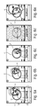
- the system which is described as an example in EP15184240.8 is exemplarily depicted in Figure 14 .
- Said system comprises a power toothbrush 1401 with an integrated 3D acceleration sensor 1402 and a wireless Bluetooth radio interface, a smartphone 1403, a smartphone holder 1404 to affix the phone 1403 to a bathroom mirror 1405 and a smartphone application.
- the smartphone application connects to the power toothbrush 1401, receives sensor data 1406 from the toothbrush 1401, gathers video frames 1407 from the smartphone's built-in front camera 1408 and processes these data streams.
- the processing is described in EP15184240.8 .
- the processing contains the determination of a brushed position, based on the result of the processed sensor data 1406 from the brush 1401 and the processed image data 1407 from the front camera 1404. Finally, both results are fused mathematically to get the most accurate, precise and stable brushing position information.
- EP15184240.8 requires certain cooperation from the consumers 1409 in order to work properly. It may consist, according to an example, of a connected power toothbrush 1401, a smartphone 1403, a mobile application, a smartphone holder 1404 with a suction cup and the user 1409 himself.
- a device for determining a position of a body portion of a user comprising a camera configured to capture the body portion of the user to obtain a pictorial representation of the body portion of the user, and a display for providing visual feedback to the user.
- the device further comprises at least one sensor for determining at least one of a roll angle, a pitch angle and a yaw angle of the device.
- the device comprises an interface for receiving picture data related with the pictorial representation of the body portion captured by the camera and for receiving sensor data related with the determined angle of the device determined by the at least one sensor.
- the device comprises an analyzer.
- the analyzer is configured to analyze, based on the picture data, whether the captured body portion is within a predetermined region of the picture captured by the camera.
- the analyzer is further configured to analyze, based on the sensor data, whether the roll angle and/or the pitch angle and/or the yaw angle of the device is within a predetermined angle range.
- the device is enabled to detect a certain body portion of the user, which may be, for instance, a face of the user when he is shaving or brushing his/her teeth.
- the display enables the device to provide instantaneous visual feedback to the user.
- the display provides immediate feedback to the user by displaying the user's chest on the display.
- images and/or messages may be displayed on the display in order to provide visual feedback to the user.
- upward directed arrows may be displayed to provide visual feedback to the user informing him/her that the camera is adjusted too low.
- a message such as a text message in a pop-up window, for instance, may be displayed on the display which text message may inform the user to re-adjust the camera.
- the user may receive a corresponding information by means of visual feedback that the relative position between him/her and the device shall be adjusted in order to capture his face, e.g. the user may move his face downwards, i.e. into the direction of the focus of the camera, and/or the device may be moved upwards, i.e. into the direction of the face of the user.
- the device provides further visual feedback to the user in order to assist him/her to determine a relative orientation between the user and the device, wherein said relative orientation is identical or approximate to a desired or predetermined relative orientation.
- the analyzer is configured to analyze whether the captured body portion, e.g. the user's face, is within a predetermined region of the picture captured by the camera.
- the user may receive instantaneous visual feedback via the display. By said instantaneous feedback, the user may be prompted to adjust the relative orientation, if necessary, such that he/she will be prompted to move his/her body portion, e.g. face, into said predetermined region of the picture.
- arrows pointing to the center of the predetermined region may be displayed on the display as an example in order to provide visual feedback to the user informing him/her to move his/her face into the direction in which the arrows point, i.e. into the predetermined region of the picture.
- the captured body portion itself e.g. the user's face, may be displayed on the display in order to provide visual feedback to the user. In this case, the user directly sees on the display which body portion is currently captured by the camera.
- the device provides a further mechanism to assist the user in determining a certain relative orientation.
- the analyzer also analyzes whether the device may be correctly angled towards the user, by analyzing angle data provided by the at least one sensor.
- the at least one sensor may provide information as to at least one of the roll angle, the pitch angle and the yaw angle of the device.
- the user may also get instantaneous feedback via the display which may display the currently determined respective angle.
- the analyzer analyzes whether the currently determined respective angle is within a predetermined angle range. Said predetermined angle range may also be visually displayed to the user via the display in order to provide a visual feedback to the user as to a current angle. If necessary, the user may adapt the relative orientation between him/her and the device, if necessary, such that the currently determined respective angle corresponds (at least partly) to the predetermined respective angle range.
- the suggested concept may provide a device configured to provide a guided system setup process for assisting a user in setting up the device such that it can be used as desired.
- the analyzer may comprise a body portion detection algorithm to determine the position of the body portion within the focus of the camera. Accordingly, the analyzer may detect a desired body portion, e.g. an arm, a leg or a face of a user. The analyzer may further be configured to track the detected body portion when the user moves said body portion within the focus of the camera. Thus, the device may be enabled to detect and track the recent position of the detected body portion within the picture captured by the camera.
- a desired body portion e.g. an arm, a leg or a face of a user.
- the analyzer may further be configured to track the detected body portion when the user moves said body portion within the focus of the camera.
- the device may be enabled to detect and track the recent position of the detected body portion within the picture captured by the camera.
- the body portion of the user may be the face of the user
- the analyzer may comprise a face detection algorithm to determine the position of the face within the focus of the camera.
- the device may be enabled to detect and track the face of a user within the picture captured by the camera.
- Conventional face tracking algorithms such as the Fraunhofer SHORE algorithm, may be used in order to detect and track the face.
- the analyzer may be configured to determine, based on at least the picture data and optionally on the angle data, a relative orientation of the device relative to the detected body portion of the user, wherein said relative orientation is a relative distance between the detected body portion and the device and/or a relative position between the detected body portion and the device along a plane that is substantially perpendicular to the orientation of the camera.
- the device may be enabled to determine whether the user moves his/her body portion forward or backward, i.e. towards the device or away from the device.
- the device may be enabled to determine whether the user may move his/her body portion into one or more of the directions left, right, upwards or downwards with respect to the device.
- the analyzer may be configured to overlay the pictorial representation of the body portion with the predetermined region of the picture and, if the analyzer analyzes that the body portion is at least partly outside the predetermined region of the picture, the device is configured to display a message and/or an image on the display in order to prompt the user to alter the relative orientation between the body portion and the device.
- the device is configured to check by means of the pictorial representation whether the captured body portion is located inside, at least partly outside or completely outside the predetermined region of the picture.
- the predetermined region of the picture may be a spot of a certain size located inside the captured picture.
- the pictorial representation, i.e. captured picture of the body portion is overlayed with the predetermined region.
- the predetermined region of the picture e.g. the spot of a certain size
- the picture of the captured body portion may be shown together within a common picture or frame.
- the predetermined region of the picture may be shown within the same image as the picture currently captured by the camera.
- the currently captured picture and the predetermined region of the picture may be mutually displayed on the display. This visualization may assist the user in altering the relative orientation between the body portion and the device until the body portion is located within the predetermined region of the picture.
- the at least one sensor may be configured to determine the at least one of a roll angle, a pitch angle and a yaw angle of the device and to display the determined roll angle and/or pitch angle and/or yaw angle of the device on the display.
- at least the pitch angle and the roll angle may be displayed by means of a level bar.
- the level bar may change its position and/or orientation on the screen depending on the respective angle determined by the at least one sensor.
- the level bar may be displayed together with a pictorial representation of the predetermined angle range, which may be a spot of a certain size, for example a horizontally extending rectangular region. This visualization may assist the user in altering the orientation of the device.
- the device may be configured to display an image and/or a message on the display prompting the user to position the device such that it comprises a roll angle and/or a pitch angle and/or a yaw angle that lies within said predetermined angle range.
- the message may be a text message that is displayed on the display, which text message informs the user to adapt the respective angle of the device.
- an image may be displayed informing the user about the deviation of the current angle from the predetermined angle.
- the image may be, for instance, a color switch of a displayed level bar.
- the level bar may be displayed in green color. However, if the device may not comprise a respective angle that is within the predetermined angle range, then the level bar may be displayed in red color.
- the predetermined angle range of the roll angle and/or the pitch angle and/or the yaw angle may lie between +3° and -3°.
- a predetermined angle may be zero degrees, wherein a deviation of +3° to -3° from said predetermined angle may represent the predetermined angle range.
- a total angle range may have a value or magnitude of 6°.
- the predetermined region of the picture may cover about 60% to 80%, and preferably 75% of the focus of the camera.
- the predetermined region covers about 60% to 80%, and preferably 75% of the picture captured by the camera.
- the predetermined region may, for instance, be a spot having a size of about 60% to 80%, and preferably 75% of the focus of the camera.
- the captured detected body portion shall preferably also cover about 60% to 80%, and preferably 75% of the picture captured by the camera. This percentage of the body portion relative to the entire picture helps in determining the current position of the body portion within the picture.
- the device may comprise a communication interface that is configured to communicate with a personal care device in order to receive information from said personal care device.
- the Communication interface may be a wireless communication interface using a wireless communication protocol such as WiFi, Bluetooth, ZigBee, WiMAX or the like.
- a method for determining a position of a body portion of a user comprising capturing the body portion of the user in order to obtain a pictorial representation of the body portion of the user, and providing visual feedback to the user.
- the method further comprises receiving angle data corresponding to at least one of a roll angle, a pitch angle and a yaw angle of a device by means of which the pictorial representation was captured.
- the method comprises receiving picture data related with the pictorial representation of the body portion, and analyzing, based on the picture data, whether the captured body portion is within a predetermined region of the picture captured by the device.
- the method comprises analyzing, based on the angle data, whether the roll angle and/or the pitch angle and/or the yaw angle of the device is within a predetermined angle range.
- a computer program for performing, when running on a computer, the above-mentioned method.
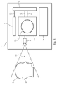
- Figure 1 shows a device 1 for determining a position of a body portion 2 of a user 3.
- the device 1 comprises a camera 4 configured to capture the body portion 2 of the user 3 to obtain a pictorial representation of the body portion 2 of the user 3.
- the device 1 further comprises a display 6 for providing visual feedback to the user 3.
- the device 1 further comprises at least one sensor 7 for determining at least one of a roll angle, a pitch angle and a yaw angle of the device 1.
- the device 1 further comprises an interface 8 for receiving picture data related with the pictorial representation 5 of the body portion 2 captured by the camera 4 and for receiving sensor data related with the determined angle of the device 1 determined by the at least one sensor 7.
- the device 1 further comprises an analyzer 9 to analyze, based on the picture data, whether the captured body portion 2 is within a predetermined region 33 of the picture captured by the camera 4, and to analyze, based on the sensor data, whether the roll angle and/or the pitch angle and/or the yaw angle of the device 1 is within a predetermined angle range.
- the body portion 2 of the user 3 is the user's head.
- the camera 4 is directed onto the user's head 2.
- the relative position or distance between the user's head 2 and the camera 4 is chosen such that the focus 10 of the camera 4 substantially captures the entire head 2 of the user 3.
- the camera 4 obtains a pictorial representation of the user's head 2. Picture data that is related with the pictorial representation is fed to the interface 8.
- the camera 4 may be connected to the interface 8 via a physical or wireless data transmission channel 12.
- the data transmission channel 12 may be configured for unidirectional or bidirectional data transmission.
- the interface 8 further receives sensor data related with the determined angle of the device 1.
- the sensor data may be provided by physical or wireless data transmission channel 13 between sensor 7 and interface 8.
- the data transmission channel 13 may be configured for unidirectional or bidirectional data transmission.
- the sensor 7 may, for instance, be an inertial sensor that is configured to determine at least one of a roll angle, a pitch angle and a yaw angle of the device 1.
- the inertial sensor may preferably be configured to determine all three angles.
- the device 1 comprises an individual sensor for each of the aforementioned three angles, i.e. a first sensor for determining the roll angle of the device 1, a second sensor fort determining the pitch angle of the device 1, and a third sensor for determining the yaw angle of the device 1.
- the interface 8 is configured to receive the respective sensor data related with the respective one of the pitch angle, roll angle and yaw angle.
- the interface 8 is configured to receive picture data related with the pictorial representation captured by the camera 4, as well as sensor data related with a current angle of the device 1 and being determined by the at least one sensor 7.
- the device 1 further comprises an analyzer 9.
- the analyzer 9 may also be connected to the interface 8 via a physical or wireless data transmission channel.
- the data transmission channel may be configured for unidirectional or bidirectional data transmission.
- the analyzer 9 may, for instance, be a CPU or any other type of logical unit that is configured to process the picture data and the sensor data, respectively.
- the analyzer 9 is configured to analyze whether the captured body portion, i.e. the user's head 2, particularly the pictorial representation of the user's head 2, is within a predetermined region of the picture captured by the camera 4.
- Said predetermined region of the picture may be a cross hair, a rectangle, a circle 33, or the like, as exemplarily shown in Figure 1 . It may also be displayed on the display 6.
- said predetermined region of the picture will be explained in more detail with reference to the following Figures, for example with reference to Figure 4B .
- the analyzer 9 is configured to analyze whether the determined roll angle and/or pitch angle and/or yaw angle is within a predetermined angle range.
- the device 1 may, for instance, be a mobile phone.
- the interface 8 may be connected with a sensor 7 that may already be available within the mobile phone 1.
- the interface 8 may further be connected with a camera 4 that may already be available within the mobile phone 1.
- the interface 8 may be connected with a display 6 that may already be available within the mobile phone 1.
- the analyzer 9 may be the CPU of the mobile phone.
- the interface 8 may be connected with the CPU 9 or be a part of the CPU 9.
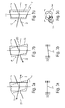
- Figures 2A, 2B and 2C depict the above mentioned three angles along which the device 1 may be oriented, namely the pitch angle, the roll angle and the yaw angle.
- Each of the Figures shows a coordinate system 20 having an X-Axis 21, a Z-Axis 22 and a Y-Axis 23.
- each of the Figures exemplarily shows the orientation of the device 1 within said coordinate system 20.
- the device 1 is shown in a first or initial position 1a. If the device 1 rotates along the X-Axis 21, it moves into a second or deflected position 1b, shown in dashed lines.
- the angle between the first position 1a and the second position 1b of the device 1 may be referred to as the pitch angle ⁇ .
- the device 1 is shown in a first or initial position 1a. If the device 1 rotates along the Z-Axis 22, it moves into a second or deflected position 1b, shown in dashed lines.
- the angle between the first position 1a and the second position 1b of the device 1 may be referred to as the roll angle ⁇ .
- the device 1 is shown in a first or initial position 1a. If the device 1 rotates along the Y-Axis 23, it moves into a second or deflected position 1 b, shown in dashed lines.
- the angle between the first position 1a and the second position 1b of the device 1 may be referred to as the yaw angle ⁇ .
- the device 1 may be configured to display the respective angle on the display 6 in order to provide visual feedback to the user 3.
- the device 1 may be configured to display a level bar on the display 6.
- An example of a level bar and a possible way of visual angle indication is shown in Figures 3A and 3B .
- the display 6 may display a level bar 31 and one or more indicator marks 32 in order to provide visual feedback to the user 3 regarding a current pitch angle and/or a current roll angle of the device 1.
- the indicator marks 32 may be represented by small lines arranged at the left side and the right side of the display 6.
- the indicator marks 32 may represent a predetermined angle range.
- the pitch angle ⁇ increases.
- this variation in the pitch angle ⁇ may be represented by an up and down movement of the level bar 31.
- the pitch angle ⁇ increases in a positive direction, and the level bar 31 moves downwards.
- the pitch angle ⁇ decreases or increases in a negative direction, and the level bar 31 moves upwards. It may also be possible that the level bar 31 moves upwards as the pitch angle ⁇ increases in a positive direction, and that the level bar 31 moves downwards as the pitch angle ⁇ increases in a negative direction.
- the roll angle ⁇ increases.
- this variation in the roll angle ⁇ may be represented by a left and right tilt of the level bar 31.
- the level bar 31 may also tilt left, as depicted in Figure 3B . Otherwise, if the device 1 turns right, the level bar 31 may also tilt right.
- a different visualization may be chosen for the yaw angle.
- two different kinds of circles 33, 34 may be displayed on the display 6 in order to provide visual feedback to the user 3 regarding a current yaw angle of the device 1.
- the first circle 33 may have an outer diameter that substantially corresponds to an inner diameter of the second circle 34. In other words, the first circle 33 may fit into the second circle 34.
- These two circles 33, 34 are only mentioned as an example for visual feedback.
- Other geometrical forms, arrows, colors, text messages, or the like may also be displayed on the display 6 in order to provide proper feedback to the user 3.
- the first circle 33 is arranged within the second circle 34 ( Figure 3C ).
- the yaw angle ⁇ increases.
- the first circle 33 may move to the left outside the second circle 34, and vice versa.
- the first circle 33 may move to the right outside the second circle 34 if the device is rotated left, and vice versa.
- the following Figures may exemplarily show some possible visualizations on the display 6 of the device 1 in order to provide visual feedback to the user 3 regarding a current pitch angle and/or roll angle and/or yaw angle of the device 1 as well as visual feedback regarding the body portion that is currently captured by the camera 4 of the device 1.
- the device 1 may be used to guide the user 3 through a setup process in order to arrange the device 1 relative to the user 3 such that the device 1 is usable by the user 3 as desired.
- a personal care device for instance a toothbrush
- the device 1 is configured to determine the position of a body portion 2 of the user 3.
- said body portion 2 of the user 3 is, just by way of example, the user's face.
- the device 1 may, for instance, be configured to determine the position of the user's face relative to the device 1.
- Figure 4A shows a screen that may be displayed on the display 6 of the device 1, when the device is started for the very first time.
- a pop-up message 41 is displayed which may present a question to the user.
- the user is asked whether he/she prefers brushing his/her teeth with his/her left hand or with his/her right hand.
- the user may choose and input his selection by clicking the respective button.
- the display 6 may be a conventional touch screen device. After having selected and clicked the respective button, the user's choice may be used in a position detection algorithm which may be performed by the device.
- Figure 4B shows a further screen that the display 6 may display to the user 3.
- Figure 4B shows a pictorial representation 5 of the user 3 which may, for example, be displayed on the display 6 in order to provide visual feedback to the user 3 regarding the body portion that is currently captured by the camera 4. Even though it may, by way of example, continuously be depicted in the Figures that the pictorial representation of the captured body portion of the user 3 is displayed on the display 6, it may also be possible that the pictorial representation of the captured body portion of the user 3 may not be displayed on the display 6.
- the pictorial representation 5 is the picture or image of the user 3 that is captured by the camera 4 of the device 1.
- the camera 4 captures a moving image sequence, e.g. a movie, of the user 3 and displays the user's image instantaneously on the display 6 of the device 1, so to say in real-time. Accordingly, when the user 3 moves relative to the device 1, then this relative movement is instantaneously shown on the display 6 so that the user 3 may always see his current position relative to the device 1.
- Figure 4B shows the visual elements that have been previously described with reference to Figures 3A, 3B and 3C , namely the level bar 31, the indicator marks 32, the first circle 33 and the second circle 34.
- the indicator marks 32 may be displayed on the left and on the right side of the display 6.
- upper indicator marks 32a and lower indicator marks 32b may be displayed.
- the level bar 31 and the indicator marks 32a, 32b may be used for indicating a pitch angle and/or a roll angle of the device 1.
- the region between the upper indicator marks 32a and the lower indicator marks 32b may represent the predetermined angle range.
- the level bar 31 is substantially horizontal, i.e. not tilted.
- the level bar 31 is positioned underneath the indicator marks 32a, 32b, particularly underneath the lower indicator marks 32b. Accordingly, the user may be informed that the device 1 may comprise a roll angle that is within the predetermined angle range, but a pitch angle that is outside the predetermined angle range.
- the device 1 is configured to display a message 42 on the display 6 prompting the user 3 to position the device 1 such that it comprises a roll angle that lies within the predetermined angle range, i.e. between the upper indicator marks 32a and the lower indicator marks 32b. According to this example, the device displays a message 42 on the display 6 informing the user 3 to tilt the camera 4 forward, or to respectively tilt the device 1 comprising the camera 4 forward.
- the device may display an alternative message 42 on the display 6 informing the user 3 to tilt the camera 4 backward, or to respectively tilt the device 1 comprising the camera 4 backward.
- an image such as an upward or downward directed arrow or the like, may be presented to the user 3.
- the message 42 and/or image may be dismissed once the device 1 has detected that it has been moved such that the level bar 31 lies within the predetermined angle range indicated by the indicator marks 32a, 32b, or after a certain time, for example after 3 seconds, whichever is longer. According to an example, messages 42 and/or images are not shown on the display 6 anymore once they are dismissed for the first time.
- the aforementioned user's selection regarding his/her preferred hand may still be displayed on the display 6 by means of softkey buttons 43, 44.
- a further softkey button 45 may be displayed on the display 6. By clicking said button 45, the user 3 may input and signal his/her desire to the device 1 to continue even though the respective determined angles (roll, pitch, yaw) may not yet be within the predetermined angle range.
- the device 1, and in particular the analyzer 9 comprises a face detection algorithm to determine the position of the user's face within the focus of the camera 4.
- the analyzer 9 may use the so-called SHORE face detection algorithm from Fraunhofer.
- the body portion of the user 5 may not necessarily be displayed on the display 6.
- the analyzer 9 is configured to process picture data related with the captured pictorial representation of the user 3 without showing any picture data or pictorial representations on the display 6.
- the analyzer 9 is configured to run a body portion detection algorithm, in particular a face detection algorithm, by using the picture data without displaying them on the display 6.
- the device 1 may comprise a respective body portion detection algorithm that is configured to detect the respective body portion within the focus of the camera 4.
- the face detection algorithm enables the analyzer 9 to detect the face of the user 3 within the pictorial representation 5 captured by the camera 4.
- the previously discussed first circle 33 is overlayed onto the pictorial representation 5 of the user 3 such that the first circle 33 substantially covers the detected face of the user 3.
- the algorithm is further configured to track the face of the user 3, once it has been detected, preferably in real-time. Accordingly, if the user 3 moves his face relative to the camera 4, the algorithm is configured to continuously detect the user's face so as to follow the user's movements.
- the user's face i.e. the first circle 33
- the inner diameter of the second circle 34 may represent the predetermined region of the picture captured by the camera 4 inside of which the user's face, i.e. the first circle 33, shall be positioned.
- the device 1, and in particular the analyzer 9, is configured to overlay the pictorial representation 5 of the user 3 with the predetermined region of the picture captured by the camera 4.
- the pictorial representation 5 of the user 3 and the predetermined region, which is represented by the second circle 34, are together displayed within the same image on the display 6, as exemplarily shown in Figure 4B .
- the face detection algorithm enables the analyzer 9 to detect the user's face which detection is represented by the first circle 33 that may be displayed on the display 6.
- the analyzer 9 analyzes whether the user's face is within the predetermined region. Stated differently, the analyzer 9 analyzes whether the first circle 33 is within the second circle 34. If the analyzer 9 analyzes that the face is at least partly outside the predetermined region of the picture, the device 1 is configured to display a message and/or an image 46 on the display 6 in order to prompt the user 3 to alter the relative orientation between the face and the device 1.
- the device 1 displays an image 46 of three consecutive arrow heads pointing into the direction into which the user 3 shall move his/her face. Accordingly, this image 46 (e.g. arrow heads) is being displayed on the display 6 in order to provide visual feedback to the user 3 informing him/her in which direction he/she shall move so as to move his/her body portion inside the predetermined region 33 of the picture captured by the camera 4.
- this image 46 e.g. arrow heads
- the image 46 may point into the direction of the center of the second circle 34. Accordingly, the user 3 may be prompted to alter the position of his/her face relative to the device 1, or at least relative to the camera 4. Additionally or alternatively, the position of the device 1 itself may be altered. In this example, the device 1 may be moved upward and right. Accordingly, the user 3 may be prompted to alter the position of the device 1 relative to his/her face. However, in the latter example, the user should take care that the level bar 31 is between the indicator marks 32a, 32b after having repositioned the device 1.
- the image 46 and/or message may be displayed as long as the detected body portion, i.e. the user's face in this example, is at least partly outside the predetermined region 34.
- the image 46 and/or message may be displayed as long as the first circle 33 is at least partly outside the second circle 34. Accordingly, the image 46 and/or message may not be displayed anymore in case the analyzer 9 analyzes that the position of the device 1 relative to the user 3 is adjusted such that the user's face is within the predetermined region.
- the setup process may be terminated.
- the device 1 may then switch to an operational mode in which it communicates with a personal device, such as a toothbrush, in order to present brushing instructions to the user via the display 6.
- Figure 4C shows a message 47 that is displayed on the display 6 if the user 3 is too far away from the device 1 or the camera 4, respectively.
- the user 3 is prompted by said message 47 to move closer.
- the message 47 is displayed on the display 6 in order to provide visual feedback to the user 3.
- Any of the previously discussed softkeys may be inactive during this display state.
- the screen as shown in Figure 4C is overlayed over the current picture from the user and the message 47 is displayed on the display 6.
- the device 1, and in particular the analyzer 9, is configured to determine a relative distance, or a variation (e.g. by a forward or a backward movement of the user 3 relative to the camera 4) of the relative distance, between the camera 4 and the user 3.
- the device 1, and in particular the analyzer 9, is also configured to determine a movement of the user 3 in front of the camera 4, which movement may be any one of a left, a right, an upward and a downward directed movement.
- the device 1, and in particular the analyzer 9, is also configured to detect a combination of the aforementioned movements.
- the analyzer 9 is configured to determine, based on at least the picture data and optionally on the sensor data a relative orientation of the device 1 relative to the detected body portion of the user 3, wherein said relative orientation may be at least one of a relative distance between the detected body portion and the device 1 (or the camera 4, respectively) and/or a relative position between the detected body portion and the device 1 (or the camera 4, respectively) along a plane that is substantially perpendicular to the orientation of the camera 4.
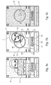
- Figure 5A exemplarily shows a screen 6 displaying an image or a pictorial representation 5 of the user 3.
- the screen displayed on the display 6 further shows the indicator marks 32a, 32b and the level bar 31.
- the screen shows the first circle 33 representing the detected face of the user 3, and the second circle 34 representing the predetermined region within the picture captured by the camera 4.
- the image 46 in the form of three consecutive arrow heads prompting the user 3 to move his/her face into the direction of the center of the second circle 34 is also displayed.
- All of these graphical elements i.e. level bar 31, indicator marks 32a, 32b, first circle 33, second circle 34, arrow heads 46, pictorial representation of the user 3, are overlayed on the camera feed, i.e. over the picture captured by the camera 4 and may be used in order to provide visual feedback to the user 3.
- the second circle 34 is a fixed circle located substantially in the middle of the screen.
- the second circle 34 indicates where the user 3 should have his/her face.
- the first circle 33 is displayed.
- the first circle 33 is displayed as a translucent circle or dot which is overlayed on the face of the user 3.
- the second circle 33 follows the user's face if the user 3 moves relative to the camera 4.
- the directional arrows 46 point from the detected face position towards the center of the second circle 34.
- the arrows 46 shall prompt the user 3 to alter the relative position between his/her face and the device 1, or the camera 4 respectively.
- the user 3 may alter his position in order to move his face into the alignment circle 34 while the device 1 itself is not moved. Additionally or alternatively, the position of the device 1 may be altered such that the user's face appears within the alignment circle 34.
- Figure 5B shows another screen that may be displayed on the display 6.
- the relative position between the device 1 and the user 3 is altered.
- the position of the user's face has moved from former right ( Figure 5A ) to the left side of the second circle 34.
- the translucent first circle 33 follows the movement of the user's face.
- the arrow heads 46 point into the direction of the center of the second circle 34.
- the level bar 31 is located underneath the lower indicator mark 32b and the level bar 31 is also tilted to the left. This indicates to the user 3 that the device 1 comprises a pitch angle that is outside the predetermined angle range, and that the device 1 further comprises a roll angle that is also outside the predetermined angle range.
- the predetermined angle range is represented by the region between the upper and the lower indicator marks 32a, 32b.
- the level bar 31 measures the phone's roll and pitch so that it can be properly vertical and facing towards the user 3.
- the level bar 31 should act as a level and move up and down as the pitch changes (e.g. as the device 1 is tilted backwards the level bar 31 would be lower as shown here).
- the level bar 31 should also tilt diagonally if the phone is rolled and no longer perpendicular to the floor (e.g. it should always remain parallel to the floor regardless of the phone's orientation).
- the indicator marks 32a, 32b are fixed guides. The level bar 31 must be aligned between these two guides 32a, 32b.
- Figure 5C depicts a further example of a screen that may be displayed on the display 6.
- the level bar 31 is now located between the upper and lower indicator marks 32a, 32b. Accordingly, this indicates towards the user 3 that the device 1 comprises a roll angle and a pitch angle which lie inside the predetermined angle range.
- the level bar 31 may change its color or contrast. As shown, the level bar 31 may change its appearance from a light contrast to a darker contrast.
- alignment guides 50 are displayed inside the second circle 34.
- a first horizontal alignment guide 51, a second horizontal alignment guide 52 and a vertical alignment guide 53 are displayed.
- the analyzer 9 analyzes that the detected body portion (i.e. the user's face in this example) is located to a predetermined extent within the predetermined region of the picture (i.e. within the second circle 34), then the analyzer 9 is configured to display alignment guides 51, 52, 53, preferably a first horizontal alignment guide 51, a second horizontal alignment guide 52 and a vertical alignment guide 53, on the display 6.
- the alignment guides 51, 52, 53 shall help the user 3 in aligning his face correctly inside the second circle 34.
- the user 3 shall be prompted to align his/her eye region with the first horizontal alignment guide 51, to align his/her mouth region with the second horizontal alignment guide 52, and to align the vertical center region of his/her face, e.g. the bridge of his/her nose, with the vertical alignment guide 53.
- alignment guides 51, 52, 53 for the eyes, nose and mouth may be displayed on the display 6.
- Figure 5D shows a further example of a screen that may be displayed on the display 6 if the user 3 has aligned his face with the alignment guides 51, 52, 53, as mentioned above.
- the user's eye region is substantially aligned with the first horizontal alignment guide 51
- the user's ,mouth region is substantially aligned with the second horizontal alignment guide 52
- the user's nose bridge is substantially aligned with the vertical alignment guide 53.
- the analyzer 9 is configured to analyze the relative position between the user 3 and the device 1 (or the camera 4, respectively) such that the detected body portion is aligned with an alignment guide 50 displayed on the display 6.
- the second circle 34 may change its appearance, e.g. by switching to a different color or contrast. In this example, the second circle 34 may switch to a darker contrast.
- a softkey button 54 may be displayed. By clicking said softkey button 54, the screen may switch to a different state, such as shown in Figure 5E for example.
- the alignment circle 34 and the level 31 may change color to indicate correct alignment.
- the continue button 54 should become enabled once the user's face and the phone 1 are aligned correctly.
- the user 3 may tap the button 54 to go to a position detection or brushing challenge timer ( Figure 5E ), for example.
- two further softkey buttons 55, 56 may be displayed during all of the above described states.
- the softkey button 55 may be tapped by the user 3 to open first time mounting instructions.
- the softkey button 56 may be tapped by the user 3 to close the calibration camera and return to a position detection or brushing challenge timer ( Figure 5E ), whichever the user 3 had come here from.
- Figure 5E shows a further example of a screen that may be displayed on the display 6.
- a Position Detection Insight Overlay 57 may be displayed over the pacer which is calibrated and ready to begin.
- Figures 5A to 5D showed an example how a relative position between the device 1 and the user 3 along a plane that is substantially perpendicular to the orientation of the camera 4 may be determined.
- Figures 5A to 5D may describe an example how the analyzer 9 is configured to determine, based on at least the picture data and optionally the sensor data (respective angles of the device 1), a relative orientation of the device 1 relative to the detected body portion of the user 3, wherein said relative orientation is a relative position between the detected body portion and the device 1 along a plane that is substantially perpendicular to the orientation of the camera 4.
- said plane that is substantially perpendicular to the orientation of the camera 4 may be the plane in which the user 3 may move left, right, up and down in front of the camera 4 without varying the distance to the camera 4, i.e. such as depicted in Figures 5A to 5D .
- Figures 6A to 6E show an example how a relative distance between the device 1 and the user 3 may be determined.
- Figures 6A to 6E may describe an example how the analyzer 9 is configured to determine, based on at least the picture data and optionally the sensor data (respective angles of the device 1), a relative orientation of the device 1 relative to the detected body portion of the user 3, wherein said relative orientation is a relative distance between the detected body portion and the device 1.
- a variation in the relative distance may be accomplished when the user 3 moves forward or backward relative to the device 1 or the camera 4, respectively.
- the pictorial representation of the user 3, i.e. the picture of the user 3 captured by the camera 4 may become smaller or larger on the display 6, depending on whether the user 3 moves away from or towards the camera 4.
- Figure 6A shows an example of a screen that may be displayed on the display 6.
- the screen substantially corresponds to the screen depicted in Figure 5A , i.e. the screen shows the level bar 31, the indicator marks 32a, 32b, the first circle 31 overlayed over the user's face, the second circle 34 and the arrow heads 46 pointing into the direction of the center of the second circle 34, in order to provide visual feedback to the user 3.
- the outer diameter of the first circle 33 may comprise substantially the same, or at least similar, dimensions as the inner diameter of the second circle 34.
- This may indicate towards the user 3 that the relative distance between his/her face and the device 1 (or the camera 4, respectively) may be correct such that the analyzer 9 may be enabled to analyze whether the user's face is within the predetermined region of the picture, i.e. within the second circle 34.
- arrows 46 should point his/her face back to the correct position.
- Figure 6B shows a situation in which the user 3 has moved further away from the device 1 or the camera 4, compared to the situation depicted in Figure 6A .
- the face detection still detects the face of the user 3 and overlays the first circle 33.
- the pictorial representation 5 of the detected face of the user 3 becomes smaller. Accordingly, also the outer diameter of the first circle 33 becomes smaller.
- the dot 33 tracking his/her face should get smaller. If the user's face gets too far away, the alignment arrows 46 should not be displayed anymore.
- Figure 6C shows a situation in which the user 3 has moved still further away from the device 1 or the camera 4, compared to the situation depicted in Figure 6B .
- the face detection still detects the face of the user 3 and overlays the first circle 33.
- the pictorial representation 5 of the detected face of the user 3 becomes even smaller. Accordingly, also the outer diameter of the first circle 33 still becomes smaller.
- the face tracking dot 33 should appear if the user 3 is a sufficient distance away to warrant warning him/her to get closer for alignment.
- Figure 11 For details as to when to trigger this tracking dot 33 while the user's face is still in the second circle 34, it is referred to Figure 11 .
- a screen such as shown in Figure 6D may be displayed on the display 6.
- a message 61 and/or an image may be displayed on the display 6 prompting the user 3 to move closer to the camera 4.
- a full screen error message 61 may be displayed on the display 6 prompting the user 3 to move closer.
- Figure 6E shows an example of a screen that may be displayed on the display 6 if the user 3 is too close to the camera 4.
- the pictorial representation of the user 3 may become larger within the picture captured by the camera 4, the closer the user 3 moves towards the camera 4.
- a screen (not shown) may be displayed on the display 6.
- a message 61 and/or an image may be displayed on the display 6 prompting the user 3 to move further away from the camera 4.
- the dot 33 tracking his/her face should get bigger. If the user's face gets too close, the alignment arrows 46 should not be displayed.
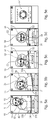
- Figures 7A to 7E show a further example of screens that may be displayed on the display 6 during use of the device 1. These screens show a Position Detection and Brushing Challenge Timer that may be displayed during use of a personal care device such as a toothbrush.
- the second circle 34 is displayed.
- six segments 71, 72, 73, 74, 75, 76 are arranged in this example.
- the upper three segments 71, 72, 73 may represent the upper set of teeth of the user, while the lower three segments 74, 75, 76 may represent the lower set of teeth of the user.
- the upper middle segment 72 may represent the upper front part of the user's teeth.
- the upper left segment 71 may represent the upper left part of the user's teeth, and so on.
- the screen shown in Figure 7A may be displayed after the device 1 has determined the position of the respective body portion of the user 3, such as described above with reference to Figures 5A to 5E .
- the screen shown in Figure 7A may correspond to the state of the screen shown in Figure 5E .
- Figure 7B shows an example of a screen that may be displayed on the display 6 when the detected body portion moves outside the predetermined region of the picture captured by the camera 4. If the user's head moves out of position during a brushing session, a corresponding visual feedback may be provided to the user 3 in that his/her face should be displayed in a circle 31 and arrows 46 should direct him/her back to the center of the second circle 34.
- FIG. 7D a message 77 and/or an image may be displayed on the display 6 prompting the user 3 to move back, i.e. away from the camera 4, or the device 1 respectively.
- a respective message 77 is displayed on the display 6.
- a respective full-screen message may be displayed on the display 6.
- Figure 7E shows an example of a screen that may be displayed on the display 6 when the user's face is not detectable, e.g. when the user is not within the focus of the camera 4. This case is shown in Figure 7E in which a message 78 and/or an image may be displayed on the display 6 informing the user 3 that his/her face is not detectable anymore. As shown in Figure 7E , a respective message 78 is displayed on the display 6. Alternatively, a respective full-screen message may be displayed on the display 6.
- the timer 79 as depicted in Figure 7E may be displayed in such a way that it is clear that position is not currently being tracked because the user 3 is out of range. Also, the shown message 78 may be displayed. The timer 79 should continue counting up as long as the toothbrush is on. Once the face is detected again, another message and/or image may be displayed for at least two seconds. Said message may contain information, such as "Oops, we could't see your face. Always face forward to get the most accurate results".
- the user's face may be displayed on the display 6, such as previously discussed by way of example with reference to Figures 7B and 7D , the user's face may be gradually faded in on the screen in order to avoid flickering.
- Such a gradually fading of the user's face is exemplarily shown in Figure 8 and is applicable for every detected body portion.
- Figure 10A shows an example of a face detection model, wherein the user's head 2 is within a tolerance zone.
- An inner circle 1010 and an outer circle 1011 may be provided in the model, wherein both circles 1010, 1011 may not be displayed on the display 6.
- a first rectangle 1012 may be circumscribed around the inner circle 1010.
- the inner region of the first rectangle 1012 may represent a tolerance zone.
- the analyzer 9 analyzes that the user's face 2 is within said tolerance zone 1012, the user's face 2 may be considered as being inside the predetermined region of the picture captured by the camera 4. Accordingly, the screen displayed on the display 6 only shows the timer 79, as depicted in Figure 9A .
- Figure 10B shows an example of the face detection model when the user's head 2 moves out of the tolerance zone, i.e. out of the previously described first rectangle 1012.
- a second rectangle 1013 which may not be displayed on the display 6, may be circumscribed around the outer circle 34.
- the inner region of the second rectangle 1013 may represent a transition zone.
- the analyzer 9 analyzes that the user's face 2 is inside said transition zone 1013, the user's face 2 may be considered as being partly inside the predetermined region of the picture captured by the camera 4.
- the screen displayed on the display 6 may show the user's face inside the first circle 33 in addition to the timer 79, as depicted in Figure 9B , in order to provide corresponding visual feedback to the user 3.
- the screen may also show the above discussed arrows 46 pointing into the direction of the center of the second circle 34 and optionally a message 77 and/or an image prompting the user 3 to move back to the center of the second circle 34.
- Figure 10C shows an example of the face detection model when the user's head 2 moves out of the transition zone, i.e. out of the previously described second rectangle 1013.
- a third rectangle 1014 which may not be displayed on the display 6, may be arranged outside the second rectangle 1013.
- the inner region of the third rectangle 1014 may represent an error zone.
- the analyzer 9 analyzes that the user's face 2 is inside said error zone 1014, the user's face 2 may be considered as being outside the predetermined region of the picture captured by the camera 4.
- the screen displayed on the display 6 may immediately show the user's face inside the first circle 33 in addition to the timer 79, as depicted in Figure 9C .
- the screen may also show the above discussed arrows 46 pointing into the direction of the center of the second circle 34 and optionally a message 77 and/or an image prompting the user 3 to move back to the center of the second circle 34.
- Figure 10D shows an example of the face detection model when the user's head 2 moves out of the error zone, i.e. out of the previously described third rectangle 1014.
- the outer region of the third rectangle 1014 may also represent an error zone.
- the analyzer 9 analyzes that the user's face 2 is outside the third rectangle 1014, the user's face 2 may be considered as being outside the predetermined region of the picture captured by the camera 4.
- the screen displayed on the display 6 may immediately show a message 78 and/or an image in addition to the timer 79, as depicted in Figure 9D .
- the message and/or image 78 may inform the user that his face is not detectable.
- Figure 10E shows an example according to which the user 3 has turned his head 2 in a first or a second direction. If the user 3 turns his head 2 in one of the directions 1015, 1016 so far that the user's face 2 is not detectable, the same screen as shown in Figure 9D may be displayed on the display 6. The screen of Figure 9D may be displayed, for instance, when the user's face is not detectable for at least three seconds.
- Figure 11 shows examples of screens that may be displayed on the display 6 depending on the relative distance between the user 3 and the device 1, or the camera 4 respectively.
- the device 1 may, for instance, be mounted on a bathroom mirror 1111.
- a first distance region 1101 is a distance region that is between 0cm and about 30cm away from the camera 4. This distance is too close for properly detecting the user's face. If the analyzer 9 analyzes that the user's face is within said first distance region 1101 for a predetermined time, e.g. for more than three seconds, a screen 1106 may be displayed on the display 6. This screen may correspond to the screen that has been previously discussed with reference to Figure 7D .
- a second distance region 1102 is a distance region that is between about 30cm and about 90cm away from the camera 4. This distance is accurate for properly detecting the user's face. If the analyzer 9 analyzes that the user's face is within said second distance region 1102, a screen 1107 may be displayed on the display 6. This screen may correspond to the screen that has been previously discussed with reference to Figure 7A .
- a third distance region 1103 is a distance region that is between about 90cm and about 110cm away from the camera 4. This distance is too far away for properly detecting the user's face. If the analyzer 9 analyzes that the user's face is within said third distance region 1103 for a predetermined time, e.g. for more than three seconds, a screen 1108 may be displayed on the display 6. This screen may correspond to the screen that has been previously discussed with reference to Figure 6B .
- a fourth distance region 1104 is a distance region that is between about 110cm and about 140cm away from the camera 4. This distance is too far away for accurately detecting the user's face. If the analyzer 9 analyzes that the user's face is within said fourth distance region 1104 a screen 1109 may be immediately displayed on the display 6. This screen may correspond to the screen that has been previously discussed with reference to Figure 6C .
- a fifth distance region 1105 is a distance region that is more than about 140cm away from the camera 4. This distance is too far away for properly detecting the user's face. If the analyzer 9 analyzes that the user's face is within said fifth distance region 1105 a screen 1110 may be immediately displayed on the display 6. This screen may correspond to the screen that has been previously discussed with reference to Figure 6D .
- this session will count as a normal brushing session instead of Position Detection.
- a screen such as depicted in Figure 12A may be displayed on the display 6. None of the position detection data will be recorded for this session.
- a corresponding message 78 and/or image may be displayed for 10 seconds, for example, and will then automatically be dismissed. The user may also dismiss it via the exit button 56 in the top-right.
- a screen only showing the brush timer 79 may be displayed on the display 6, as shown in Figure 12B .
- a regular Session Summary screen may be displayed on the display 6 followed by a popup 1201 explaining the error.
- Figure 13A depicts an example of a screen that may be displayed on the display 6 when the user 3 turns the toothbrush on to begin.
- the brush timer 79 is displayed and the second circle 34 is displayed in a certain color or shading in order to inform the user that his/her face has been properly detected.
- Figure 13B depicts an example of a screen that may be displayed during a brushing session.
- the upper left segment 71 is highlighted in order to inform the user 3 that his upper left teeth section shall be brushed.
- Figure 13C depicts an example of a screen that may be displayed on the display 6 when the analyzer 9 analyzes that the user 3 moves out of the transition zone 1013 that has been previously discussed with reference to Figure 10B .
- the brush timer 79 is displayed together with the user's face inside the first circle 33, the second circle 34, the arrows 46 pointing into the direction of the center of the second circle 34, and an optional message 77 prompting the user 3 to move back to the center. All of these graphical elements may be displayed on the display 6 in order to provide visual feedback to the user 3.
- Figure 13D depicts an example of a screen that may be displayed on the display 6 when the user's face is no longer within a range to be detected.
- the brushing timer 79 may be displayed in a lighter color or shading and an optional message 78 may be displayed informing the user that his/her face is not detectable.
- Figure 13E depicts an example of a screen that may be displayed on the display 6 when the user's face could not be detected over a certain time, e.g. for more than 30 seconds.
- the brushing timer 79 may be displayed in a lighter color or shading and an optional error message 78 may be displayed informing the user that his/her face is not detectable.
- a popup 1201 explaining the error to the user may also be displayed on the display 6.
- the error message 78 and the error popup 1201 may be displayed for a certain time, e.g. for ten seconds.
- Figure 13F depicts an example of a screen that may be displayed on the display 6 when the user's face may not be detectable but the user continues brushing.
- the screen as depicted in Figure 13F may be displayed on the display 6 in order to present the user the current status of the current brushing session.
- Figure 13G depicts an example of a screen that may be displayed on the display 6 when the user's face was not detectable for too long.
- the screen as depicted in Figure 13G may be displayed on the display 6 in order to provide a summary of the current brushing session. Stated differently, a regular summary screen may be displayed on the display 6 since the current brushing session will not record position data due to the user 3 being out of range for too long.
- An error message 1301 may be displayed on the summary screen as depicted in Figure 13G .
- the invention may be an interactive system setup process that guides users through the installation of a brushing position determination system.
- the system may take into account sensor data from a smartphone 1 to continuously measure the orientation of the phone 1 during the setup and provides corresponding feedback to the user 3 in order to enable him/her to install everything correctly.
- the system guides the user through the setup and checks face position and smartphone position continuously during the usage of the brushing application.
- the smartphone application instructs/guides/educates the consumer to set the whole system up correctly. While guiding the consumer to follow the instructions, the system simultaneously checks the proper installation.
- the system can detect when the consumer has completed the tasks. Appropriate feedback is provided. Completed setup tasks trigger the system to start working and providing the actual feedback during brushing. If the consumer changes the adjustment during usage, the system will detect this and provide corresponding instructions or actions.
- the process described below can, for instance, be used for setting the system up before using it, but can also serve as a feedback system during the usage of the brushing app. If the smartphone's position or orientation would be changed during the usage of the system, all data gathered by the at least one sensor would be bad, so an appropriate feedback during usage is required.
- the sensitivity of the sensor measurement e.g. roll and pitch of the phone, face distance, face position
- the smartphone measures with its at least one sensor, e.g. with built-in inertial sensors, during the setup and usage of the system.
- the head/face alignment is measured by the front camera 4 of the smartphone 1 and may use the Fraunhofer SHORE face detection algorithm to determine the position of the face within the camera focus.
- All measurements may have an ideal value range, a tolerance value range and an out of range value range. As long as the required face position / smartphone orientation is in the ideal value range, the system indicates that the next step can be taken, e.g. starting the brushing application. If a value is in the tolerance value range, the user is prompted to correct the orientation of the phone / position of the face/ distance to the camera. If the values are out of range, another message will ask the user to correct the position / orientation and that the system will not work at all.
- the user may be asked which hand he prefers using for brushing. This may help the algorithm to reduce the variances of the image processing which may increase feedback quality.
- On-screen guidance may provide instant feedback of what the consumer needs to do with the smartphone 1 in order to position it correctly. Every movement and orientation change of the phone 1 may be continuously measured and fed back to the user. In this case the Roll and pitch may be measured.
- the system determines a face in the camera focus and provides guidance on how far away the user should stand and whether the phone 1 is mounted at the right height.
- the system may provide feedback, that the user should turn on the light or close the blinds/ disable direct face illumination/ background light which blinds the camera.
- the DZM timer may be displayed in such a way that it is clear that position is not currently being tracked because the user is out of range. Also, a corresponding message may be shown.
- the handle of the toothbrush may trigger a vibration every second while the user's face cannot be detected. The timer should continue counting as long as the toothbrush is on.
- the disabled UI User Interface
- the corrective message, and vibrations should be automatically demised once the user's face is in view again. Once the face is detected again another message may be shown, for example for two seconds, such as a message containing the information: "Oops, we could't see your face. Always face forward to get the most accurate results"
- Position Detection may be disabled, but the timer may continue to count up.
- the DZM timer may be displayed in such a way that it is clear that position is not currently being tracked because the user is out of range. No message.
- this session will count as a normal brushing session instead of Position Detection. None of the position detection data may be recorded for this session.
- a corresponding message such as message 1201 shown in Figure 12C for example, may be displayed for ten seconds, for example, and then be automatically dismissed. The user may also dismiss it via the exit button 56 in the top-right. After dismissal the system may return to the position detection UI once the user's head is detected again. When the session is finished, show the regular Session Summary screen followed by a popup explaining the error.
- aspects have been described in the context of an apparatus, it is clear that these aspects also represent a description of the corresponding method, where a block or device corresponds to a method step or a feature of a method step. Analogously, aspects described in the context of a method step also represent a description of a corresponding block or item or feature of a corresponding apparatus.
- the inventive decomposed signal can be stored on a digital storage medium or can be transmitted on a transmission medium such as a wireless transmission medium or a wired transmission medium such as the Internet.
- embodiments of the invention can be implemented in hardware or in software.
- the implementation can be performed using a digital storage medium, for example a floppy disk, a DVD, a CD, a ROM, a PROM, an EPROM, an EEPROM or a FLASH memory, having electronically readable control signals stored thereon, which cooperate (or are capable of cooperating) with a programmable computer system such that the respective method is performed.
- a digital storage medium for example a floppy disk, a DVD, a CD, a ROM, a PROM, an EPROM, an EEPROM or a FLASH memory, having electronically readable control signals stored thereon, which cooperate (or are capable of cooperating) with a programmable computer system such that the respective method is performed.
- Some embodiments according to the invention comprise a non-transitory data carrier having electronically readable control signals, which are capable of cooperating with a programmable computer system, such that one of the methods described herein is performed.
- embodiments of the present invention can be implemented as a computer program product with a program code, the program code being operative for performing one of the methods when the computer program product runs on a computer.
- the program code may for example be stored on a machine readable carrier.
- inventions comprise the computer program for performing one of the methods described herein, stored on a machine readable carrier.
- an embodiment of the inventive method is, therefore, a computer program having a program code for performing one of the methods described herein, when the computer program runs on a computer.
- a further embodiment of the inventive methods is, therefore, a data carrier (or a digital storage medium, or a computer-readable medium) comprising, recorded thereon, the computer program for performing one of the methods described herein.
- a further embodiment of the inventive method is, therefore, a data stream or a sequence of signals representing the computer program for performing one of the methods described herein.
- the data stream or the sequence of signals may for example be configured to be transferred via a data communication connection, for example via the Internet.
- a further embodiment comprises a processing means, for example a computer, or a programmable logic device, configured to or adapted to perform one of the methods described herein.
- a processing means for example a computer, or a programmable logic device, configured to or adapted to perform one of the methods described herein.
- a further embodiment comprises a computer having installed thereon the computer program for performing one of the methods described herein.
- a programmable logic device for example a field programmable gate array
- a field programmable gate array may cooperate with a microprocessor in order to perform one of the methods described herein.
- the methods are preferably performed by any hardware apparatus.
Priority Applications (5)
| Application Number | Priority Date | Filing Date | Title |
|---|---|---|---|
| EP16155933.1A EP3207823A1 (fr) | 2016-02-16 | 2016-02-16 | Concept d'établissement d'un système interactif |
| CN201780011742.6A CN108601446A (zh) | 2016-02-16 | 2017-02-07 | 交互式系统设置概念 |
| PCT/EP2017/052664 WO2017140536A1 (fr) | 2016-02-16 | 2017-02-07 | Concept de configuration de système interactive |
| CA3013101A CA3013101A1 (fr) | 2016-02-16 | 2017-02-07 | Concept de configuration de systeme interactive |
| US15/434,989 US10713809B2 (en) | 2016-02-16 | 2017-02-16 | Interactive system setup concept |
Applications Claiming Priority (1)
| Application Number | Priority Date | Filing Date | Title |
|---|---|---|---|
| EP16155933.1A EP3207823A1 (fr) | 2016-02-16 | 2016-02-16 | Concept d'établissement d'un système interactif |
Publications (1)
| Publication Number | Publication Date |
|---|---|
| EP3207823A1 true EP3207823A1 (fr) | 2017-08-23 |
Family
ID=55405153
Family Applications (1)
| Application Number | Title | Priority Date | Filing Date |
|---|---|---|---|
| EP16155933.1A Pending EP3207823A1 (fr) | 2016-02-16 | 2016-02-16 | Concept d'établissement d'un système interactif |
Country Status (5)
| Country | Link |
|---|---|
| US (1) | US10713809B2 (fr) |
| EP (1) | EP3207823A1 (fr) |
| CN (1) | CN108601446A (fr) |
| CA (1) | CA3013101A1 (fr) |
| WO (1) | WO2017140536A1 (fr) |
Families Citing this family (29)
| Publication number | Priority date | Publication date | Assignee | Title |
|---|---|---|---|---|
| TWI439960B (zh) | 2010-04-07 | 2014-06-01 | Apple Inc | 虛擬使用者編輯環境 |
| FR3010629B1 (fr) | 2013-09-19 | 2018-02-16 | Dental Monitoring | Procede de controle du positionnement de dents |
| FR3027504B1 (fr) | 2014-10-27 | 2022-04-01 | H 43 | Procede de controle du positionnement de dents |
| FR3027711B1 (fr) | 2014-10-27 | 2018-06-15 | Dental Monitoring | Procede de controle de la dentition |
| US11245939B2 (en) * | 2015-06-26 | 2022-02-08 | Samsung Electronics Co., Ltd. | Generating and transmitting metadata for virtual reality |
| US10702206B2 (en) | 2015-06-29 | 2020-07-07 | Braun Gmbh | Toothbrush for oral cavity position detection |
| ES2964759T3 (es) | 2015-09-08 | 2024-04-09 | Braun Gmbh | Determinación de una parte del cuerpo actualmente tratada de un usuario |
| US20170206804A1 (en) * | 2015-09-17 | 2017-07-20 | Funbrush Ltd. | Interactive add-on device for kids for a toothbrush and a platform for mobile devices containing games controlled by that device |
| EP3207823A1 (fr) | 2016-02-16 | 2017-08-23 | Braun GmbH | Concept d'établissement d'un système interactif |
| DK201670609A1 (en) | 2016-06-12 | 2018-01-02 | Apple Inc | User interfaces for retrieving contextually relevant media content |
| AU2017100670C4 (en) | 2016-06-12 | 2019-11-21 | Apple Inc. | User interfaces for retrieving contextually relevant media content |
| EP3493533B1 (fr) * | 2016-08-01 | 2024-04-03 | Sony Group Corporation | Dispositif de traitement d'informations, procédé de traitement d'informations, et programme |
| KR102210150B1 (ko) * | 2016-09-23 | 2021-02-02 | 애플 인크. | 아바타 생성 및 편집 |
| FR3065364A1 (fr) * | 2017-04-19 | 2018-10-26 | Dental Monitoring | Dispositif de prise de vue dentaire |
| KR102333101B1 (ko) * | 2017-06-21 | 2021-12-01 | 삼성전자주식회사 | 관심 객체에 대한 외부 광원의 속성 정보를 제공하는 방법을 지원하는 전자 장치 |
| US10300889B2 (en) * | 2017-09-08 | 2019-05-28 | Ford Global Technologies, Llc | Iris-detection alignment for vehicle feature activation |
| DK180212B1 (en) | 2018-05-07 | 2020-08-19 | Apple Inc | USER INTERFACE FOR CREATING AVATAR |
| US11722764B2 (en) | 2018-05-07 | 2023-08-08 | Apple Inc. | Creative camera |
| US10375313B1 (en) | 2018-05-07 | 2019-08-06 | Apple Inc. | Creative camera |
| US11107261B2 (en) | 2019-01-18 | 2021-08-31 | Apple Inc. | Virtual avatar animation based on facial feature movement |
| CN110460772B (zh) * | 2019-08-14 | 2021-03-09 | 广州织点智能科技有限公司 | 摄像头自动调节方法、装置、设备和存储介质 |
| US11921998B2 (en) | 2020-05-11 | 2024-03-05 | Apple Inc. | Editing features of an avatar |
| DK202070625A1 (en) | 2020-05-11 | 2022-01-04 | Apple Inc | User interfaces related to time |
| CN115943626A (zh) * | 2020-06-10 | 2023-04-07 | 麦克赛尔株式会社 | 看护监视装置以及看护监视方法 |
| US11768649B2 (en) * | 2020-08-10 | 2023-09-26 | Samsung Electronics Co., Ltd. | Method and electronic device for projecting event information on reflector device connected to electronic device |
| JP2022175287A (ja) * | 2021-05-13 | 2022-11-25 | キヤノン株式会社 | 撮像装置、その制御方法及びプログラム |
| US11714536B2 (en) | 2021-05-21 | 2023-08-01 | Apple Inc. | Avatar sticker editor user interfaces |
| US11776190B2 (en) | 2021-06-04 | 2023-10-03 | Apple Inc. | Techniques for managing an avatar on a lock screen |
| WO2024076631A1 (fr) * | 2022-10-06 | 2024-04-11 | Google Llc | Rétroaction en temps réel pour améliorer la capture d'image |
Citations (2)
| Publication number | Priority date | Publication date | Assignee | Title |
|---|---|---|---|---|
| US8743051B1 (en) * | 2011-09-20 | 2014-06-03 | Amazon Technologies, Inc. | Mirror detection-based device functionality |
| WO2016020803A1 (fr) * | 2014-08-04 | 2016-02-11 | Sarubbo Davide | Système de vérification d'une procédure d'hygiène buccale correcte |
Family Cites Families (72)
| Publication number | Priority date | Publication date | Assignee | Title |
|---|---|---|---|---|
| US942708A (en) | 1908-01-29 | 1909-12-07 | Lucien P Blot | Drop-hammer. |
| US3783364A (en) | 1967-06-21 | 1974-01-01 | Sunbeam Corp | Electric appliance |
| US4716614A (en) | 1985-11-07 | 1988-01-05 | Jones Arthur R | Device for monitoring the process of toothbrushing |
| US5561881A (en) | 1994-03-22 | 1996-10-08 | U.S. Philips Corporation | Electric toothbrush |
| DE4439835C1 (de) | 1994-11-08 | 1996-02-08 | Braun Ag | Zahnbürste und Verfahren zur Anzeige der Putzzeitdauer |
| DE19506129A1 (de) | 1995-02-22 | 1996-08-29 | Gimelli & Co Ag | Zahnbürste |
| US5701629A (en) | 1995-07-19 | 1997-12-30 | Speciality Filaments, Inc. | Hollow brush bristle with radiating spokes |
| JPH09168428A (ja) | 1995-12-18 | 1997-06-30 | Royal Kogyo Kk | 幼児用歯磨き促進具 |
| US5796325A (en) | 1996-08-30 | 1998-08-18 | Optiva Corporation | Charging coil core insert for electric toothbrushes |
| US5864288A (en) | 1996-10-11 | 1999-01-26 | Hogan; Rory G. | Talking toothbrush holder |
| US6519579B1 (en) | 1997-03-10 | 2003-02-11 | Fraunhofer-Gesellschaft Zur Foerderung Der Angewandten Forschung E.V. | Reliable identification with preselection and rejection class |
| US6102284A (en) | 1997-04-23 | 2000-08-15 | Lxe Inc. | Cradle for holding a device |
| US5944531A (en) | 1998-04-21 | 1999-08-31 | Foley; Rita S. | Oral hygiene instructional display |
| JP3773655B2 (ja) | 1998-06-09 | 2006-05-10 | 株式会社バンダイ | 歯磨装置及び歯磨動作の評価装置 |
| US6611780B2 (en) | 1999-06-09 | 2003-08-26 | Koninklijke Philips Electronics N.V. | System for communicating operational data between an electric toothbrush and a separate control unit |
| US6754928B1 (en) | 2000-02-08 | 2004-06-29 | Howard Rosen | Brushing behavior reinforcement toothbrush and enclosed electronic game switch with grid |
| US6536068B1 (en) | 1999-12-29 | 2003-03-25 | Gillette Canada Company | Toothbrushing technique monitoring |
| DE10026859C1 (de) | 2000-05-31 | 2001-08-30 | Braun Gmbh | Elektromotorisch angetriebene Zahnbürste mit Signalgeber |
| US6808298B2 (en) | 2000-08-21 | 2004-10-26 | Todd Regan Christensen | Lighting system |
| DE10043460C2 (de) | 2000-09-04 | 2003-01-30 | Fraunhofer Ges Forschung | Auffinden von Körperpartien durch Auswerten von Kantenrichtungsinformation |
| FR2832298B1 (fr) | 2000-09-20 | 2004-02-20 | Audians | Dispositif de brossage de dents |
| DK1367958T3 (da) | 2001-03-14 | 2008-01-28 | Braun Gmbh | Anordning til tandrensning |
| DE10159395B4 (de) | 2001-12-04 | 2010-11-11 | Braun Gmbh | Vorrichtung zur Zahnreinigung |
| US20030115694A1 (en) | 2001-12-20 | 2003-06-26 | Koninklijke Philips Electronics N.V. | Toothbrush having a brushhead portion which contains a memory device for communicating with a microcontroller in a handle portion of the toothbrush or other device |
| US6902397B2 (en) | 2002-08-01 | 2005-06-07 | Sunstar Americas, Inc. | Enhanced dental hygiene system with direct UVA photoexcitation |
| US6752627B2 (en) | 2002-09-13 | 2004-06-22 | Chang Gung University | Light emitting tooth brush having whitening and sterilizing effects |
| US20060216013A1 (en) | 2003-02-12 | 2006-09-28 | Christian Kueblbeck | Adjustment of an image recorder with dynamic measuring fields |
| US20060040246A1 (en) | 2004-08-18 | 2006-02-23 | Min Ding | Interactive Toothbrush Game |
| US20090092955A1 (en) | 2005-06-20 | 2009-04-09 | Jin-Sang Hwang | Tooth brushing pattern analyzing/modifying device, method and system for interactively modifying tooth brushing behavior |
| WO2007032015A2 (fr) | 2005-09-18 | 2007-03-22 | Emad Gith | Brosse a dents |
| US7748069B2 (en) | 2005-12-15 | 2010-07-06 | Cynthia A Dawley | Multimedia toothbrush (toothpix) |
| CN101340856B (zh) | 2005-12-21 | 2012-03-14 | 皇家飞利浦电子股份有限公司 | 用于选择电动牙刷中操作模式的系统 |
| US7411511B2 (en) | 2006-02-07 | 2008-08-12 | The Procter & Gamble Company | Interactive packaging for development of personal hygiene habits |
| US7976388B2 (en) | 2006-03-24 | 2011-07-12 | Umagination Labs, L.P. | Oral care gaming system with electronic game |
| JP5222284B2 (ja) | 2006-04-20 | 2013-06-26 | コーニンクレッカ フィリップス エレクトロニクス エヌ ヴィ | 電気歯ブラシの動作モードに関するシステム |
| US20080109973A1 (en) | 2006-11-15 | 2008-05-15 | Farrell Mark E | Personal care products and methods |
| US8201295B2 (en) | 2007-02-16 | 2012-06-19 | Colgate-Palmolive Company | Oral care implement having user-interactive display and moving head |
| US7890193B2 (en) | 2007-08-15 | 2011-02-15 | Tingey Terrell F | Oral device |
| KR100947046B1 (ko) | 2007-11-19 | 2010-03-10 | 황진상 | 운동체 자세 추적 장치, 운동체 자세 추적 방법, 이를이용한 칫솔 자세 추적 장치 및 칫솔 자세 추적 방법 |
| KR101564459B1 (ko) | 2008-02-27 | 2015-10-30 | 코닌클리케 필립스 엔.브이. | 칫솔에 대한 덴탈 위치 추적 시스템 |
| JP5359210B2 (ja) | 2008-03-14 | 2013-12-04 | オムロンヘルスケア株式会社 | 電動歯ブラシ |
| JP5293101B2 (ja) | 2008-03-14 | 2013-09-18 | オムロンヘルスケア株式会社 | 電動歯ブラシ |
| BRPI0822490A2 (pt) | 2008-05-07 | 2015-06-16 | Colgate Palmolive Co | Implemento para cuidado oral, método para emitir sinais de áudio a partir de um implemento de cuidado oral, e, aparelho de áudio |
| FI20085488A0 (fi) | 2008-05-23 | 2008-05-23 | Pump & Brush Finland Oy | Älykäs hammasharjamonitorointilaite |
| JP5251265B2 (ja) | 2008-06-02 | 2013-07-31 | オムロンヘルスケア株式会社 | 電動歯ブラシ |
| DE102008027317B4 (de) | 2008-06-07 | 2011-11-10 | Gilbert Duong | Zahnputznavigationssystem zur Kontrolle des Zähneputzens |
| US9072370B2 (en) | 2008-06-19 | 2015-07-07 | Colgate-Palmolive Company | User health profiles derived from oral care implements |
| EP2189198B1 (fr) | 2008-11-20 | 2017-06-21 | Braun GmbH | Appareil de soin du corps à usage personnel |
| US20100186234A1 (en) | 2009-01-28 | 2010-07-29 | Yehuda Binder | Electric shaver with imaging capability |
| JP5365277B2 (ja) | 2009-03-17 | 2013-12-11 | オムロンヘルスケア株式会社 | 電動歯ブラシ |
| DE102009017772A1 (de) | 2009-04-16 | 2010-11-04 | Fraunhofer-Gesellschaft zur Förderung der angewandten Forschung e.V. | Verfahren und System zum Erkennen eines Objektes, und Verfahren und System zum Erzeugen einer Markierung in einer Bildschirmdarstellung mittels eines berührungslos gestikgesteuerten Bildschirmzeigers |
| CA2761432C (fr) | 2009-05-08 | 2015-01-20 | The Gillette Company | Systemes, produits et methodes de soin personnel |
| CN102802465B (zh) | 2009-06-26 | 2016-05-11 | 吉列公司 | 用于牙刷的压力指示灯 |
| BR112012006744B1 (pt) * | 2009-09-27 | 2021-05-25 | Zte Corporation | método para transição de situação, aplicado a um processo de conexão de acesso de ip local de um elemento de rede lateral sem fio ou uma porta de estação base principal e aparelho para transição de situação |
| DE102009048117A1 (de) | 2009-10-02 | 2011-04-07 | Fraunhofer-Gesellschaft zur Förderung der angewandten Forschung e.V. | Verfahren und Vorrichtung zum Erkennen einer Fehldetektion eines Objektss in einem Bild |
| DE102009048118B4 (de) | 2009-10-02 | 2020-06-18 | Fraunhofer-Gesellschaft zur Förderung der angewandten Forschung e.V. | Verfahren und Vorrichtung zum Verwalten von Objektansichtsdaten in einer Objektdatenbank |
| EP2512290B1 (fr) | 2009-12-17 | 2018-04-18 | Unilever PLC | Système de suivi de mouvement d'une brosse à dents |
| JP5482209B2 (ja) | 2010-01-08 | 2014-05-07 | オムロンヘルスケア株式会社 | 電動歯ブラシ |
| JP2011146049A (ja) | 2011-02-04 | 2011-07-28 | Denso Corp | 人物検出装置、人物検出プログラム、作動制御装置、および衝突緩和装置 |
| US20140065588A1 (en) | 2012-08-31 | 2014-03-06 | Ideas That Work, Llc | Toothbrush Training System |
| JP6095053B2 (ja) | 2012-12-27 | 2017-03-15 | 日立マクセル株式会社 | 美容システム |
| US10172552B2 (en) | 2013-06-19 | 2019-01-08 | Benjamin Ohmer | Method for determining and analyzing movement patterns during dental treatment |
| EP2833325A1 (fr) | 2013-07-30 | 2015-02-04 | Fraunhofer-Gesellschaft zur Förderung der angewandten Forschung e.V. | Appareil et procédé de détection et de suivi d'objet à ressource adaptative |
| US10172443B2 (en) | 2013-08-11 | 2019-01-08 | Yong-Jing Wang | Oral care tools and systems |
| US10064711B1 (en) | 2013-09-23 | 2018-09-04 | Click Care LLC | Smart toothbrush and floss method and system |
| KR102254849B1 (ko) * | 2014-07-19 | 2021-05-25 | 삼성전자주식회사 | 프로비져닝 프로파일 처리 방법 및 이를 지원하는 전자 장치 |
| EP3420849A1 (fr) | 2014-12-22 | 2019-01-02 | Sunstar Inc. | Système, dispositif et programme d'aide au brossage |
| US10702206B2 (en) | 2015-06-29 | 2020-07-07 | Braun Gmbh | Toothbrush for oral cavity position detection |
| WO2017001399A1 (fr) | 2015-06-29 | 2017-01-05 | Koninklijke Philips N.V. | Procédés et systèmes pour l'extraction de caractéristiques de mouvement d'un utilisateur à l'aide d'un capteur à effet hall afin de fournir une rétroaction à l'utilisateur |
| CN105120167B (zh) * | 2015-08-31 | 2018-11-06 | 广州市幸福网络技术有限公司 | 一种证照相机及证照拍摄方法 |
| ES2964759T3 (es) | 2015-09-08 | 2024-04-09 | Braun Gmbh | Determinación de una parte del cuerpo actualmente tratada de un usuario |
| EP3207823A1 (fr) | 2016-02-16 | 2017-08-23 | Braun GmbH | Concept d'établissement d'un système interactif |
-
2016
- 2016-02-16 EP EP16155933.1A patent/EP3207823A1/fr active Pending
-
2017
- 2017-02-07 CN CN201780011742.6A patent/CN108601446A/zh active Pending
- 2017-02-07 WO PCT/EP2017/052664 patent/WO2017140536A1/fr active Application Filing
- 2017-02-07 CA CA3013101A patent/CA3013101A1/fr not_active Abandoned
- 2017-02-16 US US15/434,989 patent/US10713809B2/en active Active
Patent Citations (2)
| Publication number | Priority date | Publication date | Assignee | Title |
|---|---|---|---|---|
| US8743051B1 (en) * | 2011-09-20 | 2014-06-03 | Amazon Technologies, Inc. | Mirror detection-based device functionality |
| WO2016020803A1 (fr) * | 2014-08-04 | 2016-02-11 | Sarubbo Davide | Système de vérification d'une procédure d'hygiène buccale correcte |
Also Published As
| Publication number | Publication date |
|---|---|
| US20170236298A1 (en) | 2017-08-17 |
| US10713809B2 (en) | 2020-07-14 |
| CA3013101A1 (fr) | 2017-08-24 |
| CN108601446A (zh) | 2018-09-28 |
| WO2017140536A1 (fr) | 2017-08-24 |
Similar Documents
| Publication | Publication Date | Title |
|---|---|---|
| US10713809B2 (en) | Interactive system setup concept | |
| US11524368B2 (en) | Augmented vision system with active welder guidance | |
| US10096162B2 (en) | Headset vision system for portable devices that provides an augmented reality display and/or a virtual reality display | |
| RU2644265C2 (ru) | Устройство отображения изображения и устройство для ввода информации | |
| US10901505B1 (en) | Eye-based activation and tool selection systems and methods | |
| WO2014156146A1 (fr) | Dispositif de miroir électronique | |
| CN107111749A (zh) | 用于改进的显示的系统和方法 | |
| KR102132367B1 (ko) | 눈썹 모습 가이드 디바이스 및 방법 | |
| JP6515542B2 (ja) | 眼鏡装用画像解析装置、眼鏡装用画像解析方法、及び眼鏡装用画像解析プログラム | |
| US11448903B2 (en) | Method for correcting centering parameters and/or an axial position and corresponding computer program and methods | |
| WO2017126195A1 (fr) | Appareil et procede de traitement d'informations, et programme y relatif | |
| CN110352033A (zh) | 用眼睛追踪装置确定眼睛睁开度 | |
| KR101709611B1 (ko) | 디스플레이와 카메라가 장착된 스마트 안경과 이를 이용한 공간 터치 입력 및 보정 방법 | |
| JP6850903B2 (ja) | 認識力矯正のための視力訓練装置 | |
| JP2007232753A (ja) | 眼鏡仕様設定装置及び視野検出装置 | |
| JP4811683B2 (ja) | 視野検出装置 | |
| TWI530821B (zh) | 頭戴式顯示系統及其操作方法 | |
| JP6507252B2 (ja) | 機器操作装置、機器操作方法、及び電子機器システム | |
| US20220012922A1 (en) | Information processing apparatus, information processing method, and computer readable medium | |
| WO2014061294A1 (fr) | Procédé de mesure de position de pupille et procédé de fabrication de lentille bifocale | |
| JP5900165B2 (ja) | 視線検出装置および視線検出方法 | |
| JP2017033195A (ja) | 透過型ウェアラブル端末、データ処理装置、及びデータ処理システム | |
| JP2021170027A (ja) | レンズメータ | |
| JP2017181657A (ja) | 眼鏡装用画像解析装置、眼鏡装用画像解析方法、及び眼鏡装用画像解析プログラム | |
| GB2589255A (en) | System and method for modifying image enhancement parameters for a portable display |
Legal Events
| Date | Code | Title | Description |
|---|---|---|---|
| PUAI | Public reference made under article 153(3) epc to a published international application that has entered the european phase |
Free format text: ORIGINAL CODE: 0009012 |
|
| STAA | Information on the status of an ep patent application or granted ep patent |
Free format text: STATUS: THE APPLICATION HAS BEEN PUBLISHED |
|
| AK | Designated contracting states |
Kind code of ref document: A1 Designated state(s): AL AT BE BG CH CY CZ DE DK EE ES FI FR GB GR HR HU IE IS IT LI LT LU LV MC MK MT NL NO PL PT RO RS SE SI SK SM TR |
|
| AX | Request for extension of the european patent |
Extension state: BA ME |
|
| STAA | Information on the status of an ep patent application or granted ep patent |
Free format text: STATUS: REQUEST FOR EXAMINATION WAS MADE |
|
| 17P | Request for examination filed |
Effective date: 20180215 |
|
| RBV | Designated contracting states (corrected) |
Designated state(s): AL AT BE BG CH CY CZ DE DK EE ES FI FR GB GR HR HU IE IS IT LI LT LU LV MC MK MT NL NO PL PT RO RS SE SI SK SM TR |
|
| STAA | Information on the status of an ep patent application or granted ep patent |
Free format text: STATUS: EXAMINATION IS IN PROGRESS |
|
| 17Q | First examination report despatched |
Effective date: 20181030 |
|
| STAA | Information on the status of an ep patent application or granted ep patent |
Free format text: STATUS: EXAMINATION IS IN PROGRESS |
|
| APBK | Appeal reference recorded |
Free format text: ORIGINAL CODE: EPIDOSNREFNE |
|
| APBN | Date of receipt of notice of appeal recorded |
Free format text: ORIGINAL CODE: EPIDOSNNOA2E |
|
| APBR | Date of receipt of statement of grounds of appeal recorded |
Free format text: ORIGINAL CODE: EPIDOSNNOA3E |
|
| APAV | Appeal reference deleted |
Free format text: ORIGINAL CODE: EPIDOSDREFNE |
|
| APAF | Appeal reference modified |
Free format text: ORIGINAL CODE: EPIDOSCREFNE |
|
| P01 | Opt-out of the competence of the unified patent court (upc) registered |
Effective date: 20230430 |
|
| APBX | Invitation to file observations in appeal sent |
Free format text: ORIGINAL CODE: EPIDOSNOBA2E |
|
| APBZ | Receipt of observations in appeal recorded |
Free format text: ORIGINAL CODE: EPIDOSNOBA4E |
|
| APBT | Appeal procedure closed |
Free format text: ORIGINAL CODE: EPIDOSNNOA9E |