EP3207190B1 - Unit for covering and uncovering a surface using self-propelled adjustable slats - Google Patents
Unit for covering and uncovering a surface using self-propelled adjustable slats Download PDFInfo
- Publication number
- EP3207190B1 EP3207190B1 EP15793866.3A EP15793866A EP3207190B1 EP 3207190 B1 EP3207190 B1 EP 3207190B1 EP 15793866 A EP15793866 A EP 15793866A EP 3207190 B1 EP3207190 B1 EP 3207190B1
- Authority
- EP
- European Patent Office
- Prior art keywords
- slat
- orientation
- slats
- movement
- blades
- Prior art date
- Legal status (The legal status is an assumption and is not a legal conclusion. Google has not performed a legal analysis and makes no representation as to the accuracy of the status listed.)
- Active
Links
- 238000011144 upstream manufacturing Methods 0.000 claims description 4
- 238000000926 separation method Methods 0.000 claims 1
- 238000006073 displacement reaction Methods 0.000 description 65
- 238000009434 installation Methods 0.000 description 32
- 208000031968 Cadaver Diseases 0.000 description 5
- 238000005192 partition Methods 0.000 description 5
- 230000001681 protective effect Effects 0.000 description 4
- 230000001360 synchronised effect Effects 0.000 description 3
- 238000001514 detection method Methods 0.000 description 1
- 238000001125 extrusion Methods 0.000 description 1
- 238000004519 manufacturing process Methods 0.000 description 1
- 230000002441 reversible effect Effects 0.000 description 1
- 238000009423 ventilation Methods 0.000 description 1
Images


Classifications
-
- E—FIXED CONSTRUCTIONS
- E04—BUILDING
- E04F—FINISHING WORK ON BUILDINGS, e.g. STAIRS, FLOORS
- E04F10/00—Sunshades, e.g. Florentine blinds or jalousies; Outside screens; Awnings or baldachins
- E04F10/08—Sunshades, e.g. Florentine blinds or jalousies; Outside screens; Awnings or baldachins of a plurality of similar rigid parts, e.g. slabs, lamellae
- E04F10/10—Sunshades, e.g. Florentine blinds or jalousies; Outside screens; Awnings or baldachins of a plurality of similar rigid parts, e.g. slabs, lamellae collapsible or extensible; metallic Florentine blinds; awnings with movable parts such as louvres
-
- E—FIXED CONSTRUCTIONS
- E04—BUILDING
- E04B—GENERAL BUILDING CONSTRUCTIONS; WALLS, e.g. PARTITIONS; ROOFS; FLOORS; CEILINGS; INSULATION OR OTHER PROTECTION OF BUILDINGS
- E04B7/00—Roofs; Roof construction with regard to insulation
- E04B7/16—Roof structures with movable roof parts
- E04B7/163—Roof structures with movable roof parts characterised by a pivoting movement of the movable roof parts
-
- E—FIXED CONSTRUCTIONS
- E04—BUILDING
- E04B—GENERAL BUILDING CONSTRUCTIONS; WALLS, e.g. PARTITIONS; ROOFS; FLOORS; CEILINGS; INSULATION OR OTHER PROTECTION OF BUILDINGS
- E04B7/00—Roofs; Roof construction with regard to insulation
- E04B7/16—Roof structures with movable roof parts
- E04B7/166—Roof structures with movable roof parts characterised by a translation movement of the movable roof part, with or without additional movements
-
- E—FIXED CONSTRUCTIONS
- E05—LOCKS; KEYS; WINDOW OR DOOR FITTINGS; SAFES
- E05F—DEVICES FOR MOVING WINGS INTO OPEN OR CLOSED POSITION; CHECKS FOR WINGS; WING FITTINGS NOT OTHERWISE PROVIDED FOR, CONCERNED WITH THE FUNCTIONING OF THE WING
- E05F15/00—Power-operated mechanisms for wings
- E05F15/60—Power-operated mechanisms for wings using electrical actuators
- E05F15/603—Power-operated mechanisms for wings using electrical actuators using rotary electromotors
- E05F15/611—Power-operated mechanisms for wings using electrical actuators using rotary electromotors for swinging wings
- E05F15/616—Power-operated mechanisms for wings using electrical actuators using rotary electromotors for swinging wings operated by push-pull mechanisms
- E05F15/619—Power-operated mechanisms for wings using electrical actuators using rotary electromotors for swinging wings operated by push-pull mechanisms using flexible or rigid rack-and-pinion arrangements
-
- E—FIXED CONSTRUCTIONS
- E06—DOORS, WINDOWS, SHUTTERS, OR ROLLER BLINDS IN GENERAL; LADDERS
- E06B—FIXED OR MOVABLE CLOSURES FOR OPENINGS IN BUILDINGS, VEHICLES, FENCES OR LIKE ENCLOSURES IN GENERAL, e.g. DOORS, WINDOWS, BLINDS, GATES
- E06B7/00—Special arrangements or measures in connection with doors or windows
- E06B7/02—Special arrangements or measures in connection with doors or windows for providing ventilation, e.g. through double windows; Arrangement of ventilation roses
- E06B7/08—Louvre doors, windows or grilles
- E06B7/084—Louvre doors, windows or grilles with rotatable lamellae
-
- E—FIXED CONSTRUCTIONS
- E05—LOCKS; KEYS; WINDOW OR DOOR FITTINGS; SAFES
- E05Y—INDEXING SCHEME ASSOCIATED WITH SUBCLASSES E05D AND E05F, RELATING TO CONSTRUCTION ELEMENTS, ELECTRIC CONTROL, POWER SUPPLY, POWER SIGNAL OR TRANSMISSION, USER INTERFACES, MOUNTING OR COUPLING, DETAILS, ACCESSORIES, AUXILIARY OPERATIONS NOT OTHERWISE PROVIDED FOR, APPLICATION THEREOF
- E05Y2900/00—Application of doors, windows, wings or fittings thereof
- E05Y2900/10—Application of doors, windows, wings or fittings thereof for buildings or parts thereof
- E05Y2900/13—Type of wing
- E05Y2900/146—Shutters
Definitions
- the present invention relates to the technical field of installations for covering and uncovering a surface using steerable blades extending parallel to each other in order to constitute a protective or closure screen of a surface in the general sense, these blades steerable having the possibility in the deployed position relative to the surface, to open or close according to particular weather conditions.
- the object of the invention is for many applications to constitute in particular a roof covering part of pergolas or terraces for example, or a protective screen for doors or windows.
- this roof Compared to a fixed roof that only protects a space from the rain and the sun, this roof also offers the possibility to control, at will, the ventilation and sunshine of the space equipped with such a roof
- This openable roof however has the disadvantage of leaving permanently blades orientable above the surface to be covered, which can be a disadvantage especially during a long period of no sun.
- Each orientation and displacement mechanism comprises, on the one hand, an endless chain or belt mounted endlessly between fixed return pulleys and having an outer and an inner side, and on the other hand, an internal belt mounted without end between fixed return pulleys and having an outer strand and an inner strand which extends vis-à-vis the inner strand of the outer belt to delimit between them a drive corridor for the blades.
- Each orientation and displacement mechanism comprises a synchronized motorization system of the external belts and a synchronized motorization system of the internal belts. The motorization of the motorization systems is controlled for, on the one hand, moving in the same direction the inner strands to move the blades in translation in the drive lane and, on the other hand, move the inner strands in reverse directions to orient the blades.
- Each orientation and displacement mechanism comprises a blade distribution device driven by the synchronized motorization systems of the belts and adapted to, in a direction of movement of the strands, successively engage in a constant spacing pitch, the blades in the driving lane and, in a direction of opposite movement, successively clear the blades of the drive lane so that they occupy their stored position.
- This installation is not designed to be a roof and is in practice unsuitable to cover a relatively large opening.
- Another disadvantage of such an installation is the need to provide a blade storage magazine.
- This storage warehouse is arranged either to encroach on the surface to be covered or in the extension of the surface to be covered if a location is available for this purpose.
- the patent EP 1 595 053 describes a mechanism for closing an opening from blades each provided at each of their ends, a nut cooperating with a motorized screw extending over the entire length of the opening.
- the nuts are engaged in a guide rail to ensure the translation of the blades during the rotation of the screws.
- This mechanism also comprises, at a slide storage magazine in the folded position, a rack cooperating with the nuts to distribute the blades at a constant pitch or ensure their stacking in the store.
- each end of the blades is provided with a roller cooperating with a system ensuring the orientation of the blades.
- the patent application WO 2012/107350 discloses a thermal shutter installation for window comprising a series of orientable flaps extending parallel to each other, each being supported by a guide at each of its ends.
- the installation comprises on both sides flaps, threaded rods cooperating with a gear box fitted to each flap guide.
- the guides of each shutter are provided with motors for orienting the shutters and for moving the shutters independently of one another.
- the present invention aims to overcome the drawbacks of the prior art by proposing a simple and inexpensive installation to cover and discover, with the aid of steerable blades, a vertical as well as horizontal surface which has variable dimensions in a wide range that can reach large dimensions.
- the present invention aims to provide a completely modular installation for easily adapting to the dimensions of the surface to be covered, while offering the advantage of being able to guide at will the blades of various areas of the surface in different positions.
- Another object of the invention is to propose an installation that does not require dedicating a space for storing the blades in the folded position.
- the object of the invention relates to a plant 1 for covering and uncovering a surface 2 by a series of movable blades 3 extending one behind the other preferably being all identical and parallel to each other along their longitudinal axis.
- Each orientable blade 3 has a generally rectangular shape delimited by first and second longitudinal edges 3 1 and 3 2 parallel to one another and interconnected by first and second parallel end edges 3 3 and 3 4 also between them.
- the number and dimensions of the adjustable blades are adapted to the dimensions of the rectangular surface 2 to be covered.
- the slats 3 are able to form together a rectangular screen defined firstly by the longitudinal edge 3 1 of the first blade 3 and the longitudinal edge 2 of the 3 last blade 3 and on the other hand, by all of the first end edges 3 3 of the blades aligned together and by the set of second end edges 3 4 of the blades aligned together.
- the blades 3 are provided at each of their end edges with a pivot axis 4 to allow in particular their orientation.
- the installation 1 comprises a mechanism I for orienting the blades 3 according to their pivot axis 4 in order to ensure the pivoting of at least some and in a general manner of the set of blades 3 so that the longitudinal edges 3 1 , 3 2 adjacent blades are joined to close the corresponding surface or are non-contiguous to open the surface 2.
- the steerable blades 3 can thus form in a zone Z 1 , a screen to the extent that the longitudinal edges of the blades are contiguous with the longitudinal edges of adjacent blades.
- the blades 3 are deployed above the surface in an upright or open position.
- this example of deployment of the blades 3 is given by way of illustration only to the extent that the blades 3 can be deployed and oriented in many other configurations as will be better understood in the following description.
- the installation according to the invention also comprises a displacement system II of the blades 3 between a stowed position ( Fig . 1 ) and a position partially or fully deployed facing the surface 2 ( Fig . 2 and 3 ).
- the blades 3 are contiguous to each other between a row head blade and a storage edge 5 1 of a supporting structure or frame 5.
- the blades 3 can not be oriented and the blades 3 occupy an erect position, that is to say that the blades are located in parallel planes substantially perpendicular to the surface 2, namely vertical in the illustrated example.
- the systems I and II ensure the displacement and orientation of the blades 3 so that they together form at least one protective screen opening and closing at will.
- this screen forms a roof or a protective flap that can completely cover the surface 2 or only a portion of the surface 2, with the possibility of orientation of the blades on demand when the blades are not in the stowed position .
- the installation 1 also comprises two guide tracks 8 guiding in translation for the blades 3 between a stowed position in which the blades are contiguous to each other ( Fig . 1 ) and an extended position in which at least some or all of the blades 3 are deployed opposite the surface 2 ( Fig . 2, 3 ).
- the guideways 8 are arranged on the supporting structure of the frame 5 made in any appropriate manner depending on the intended applications and surrounding the surface 2 to be covered to advantageously form a frame.
- This supporting structure 5 advantageously comprises two longitudinal sections 5 2 and 5 3 extending parallel to one another on two opposite sides of the surface 2 and parallel to the guide tracks 8.
- longitudinal sections 5 2 and 5 3 are interconnected at their end by connection profiles 5 1 and 5 4 (not shown) together forming a frame delimiting the surface 2.
- One of the connecting sections 5 4 delimits the edge for the longitudinal edge 3 1 of the first blade while the other section 5 1 , delimits the storage edge for the longitudinal edge of the last blade 3.
- the first blade and the last blade are taken into consideration the direction of Deployment of the blades represented by the arrow F for which the blades pass from the stowed position to the deployed position.
- the first and last blades are considered to be the same as those designated during the deployment operation.
- the installation 1 according to the invention is intended to be fixed by any appropriate means on a carrier structure not shown adapted to the intended application.
- the supporting structure 5 comprises posts supporting the frame formed by the connecting sections and the longitudinal sections.
- each blade 3 is supported at each of its ends more precisely by its pivot axes 4, by a set of two carriages 10 1 , 10 2 guided in translation along the guide tracks 8.
- Each blade 3 is thus supported by its pivot axis 4, with two carriages 10 1, 10 2 moving in translation along the guide tracks between the stowed position and the deployed position.
- each carriage 10 1 , 10 2 is equipped with a guide bearing 11 cooperating with a guideway 8.
- the displacement system II comprises for each pair of carriages 10 1 , 10 2 equipping a blade, preferably two displacement motors 12 each mounted on a carriage.
- each blade 3 is motorized by two motors to balance the forces applied to the blades 3.
- the displacement motors 12 are electric motors for example to direct current brushes, connected to a power source via connection cables not shown.
- each blade 3 can also be oriented individually.
- the orientation system I comprises for each pair of trolleys equipping a blade, at least one and in the illustrated example, a single orientation motor 14 on one of the two trolleys 10 1 and 10 2 equipping a blade 3.
- Each orientation motor 14 is angularly connected with a pivot axis 4 to place the blade 3 in a determined angular position (perpendicular to the surface 2, ie vertical in the case of a pergola), closing ( in horizontal position) or intermediate between these two vertical and horizontal positions.
- each blade 3 is thus supported, at one of its ends, by a first carriage 10 1 carrying only a displacement motor 12 and, at its opposite end, by a second carriage 10 2 carrying a displacement motor 12 and an orientation motor 14.
- the carriages 10 2 provided with a displacement motor 12 and an orientation motor 14 on the one hand and the carriages 10 1 provided with a displacement motor 12 on the other hand are mounted alternately from one blade to the other on each side of the surface 2 to cover or to discover.
- the first and second carriages are mounted alternately on each longitudinal side of the supporting structure.
- Each carriage 10 1 , 10 2 has a main body 15 of generally elongate parallelepipedal shape extending mainly along the axis of pivoting 4.
- the bodies 15 of the first and second carriages are not identical to save space in space. stowed position.
- the body main 15 of the second carriages 10 2 have a length taken in the direction of extension of the blades 3 , smaller than that of the main body of the first carriages 10 1 .
- the displacement motor 12 is mounted at the end of the main body 15 of the first carriages 10 1 , thus allowing this main body 15 to have a narrowed shape to receive the main body of a second carriage 10 2 .
- the main body 15 of the first and second trolleys are nested into each other in the stowed position.
- each displacement motor 12 is mounted in any appropriate manner on the main body 15 of each carriage 10 1 , 10 2 .
- Each displacement motor 12 rotates a pinion 17 driving in translation a blade 3.
- Each pinion 17 cooperates with a rack 18 mounted on the supporting structure 5 in a direction parallel to the guideway 8 and along the entire length of the track guide to allow the translation of the blades between their stored and deployed positions.
- each rack 18 is made by a toothed belt fixed on the supporting structure 5.
- each rack 18 is mounted on the upper face of a median partition 5a presented by each longitudinal section 5 2 , 5 3 .
- each longitudinal section 5 2 , 5 3 has a web 5b extending horizontally and from which rises the median wall 5a and on both sides, an outer flange 5c and an inner flange 5d.
- the median partition 5a is equipped with the guiding path 8 made below the outer face receiving the rack 18.
- the guide path 8 is made by a circular profile rail extending in part in a housing arranged in the partition to allow mounting of the guide bearing 11.
- each longitudinal section 5 2 , 5 3 is produced by extrusion.
- the profiles can be assembled end to end at will to adapt to the dimensions of the surface 2 to cover.
- the median partition 5a and the inner wing 5d delimit between they a gutter 5e in line with which extend the end edges of the blades to possibly recover rainwater.
- the longitudinal sections 5 2 , 5 3 which are open may advantageously be closed by means of a cover 19 which protects the carriages and is mounted between the outer flange 5 and the median partition 5a .
- This cover 19 is provided with brushes 19 1 ( Fig . 5 ) for the passage of pivot axes 4.
- each guide bearing 11 is connected to the main body 15 of the carriages 10 1 , 10 2 via a connecting pin 20 of preferably removable character.
- the connecting pin 20 extends substantially perpendicular to the rail 8.
- the connecting pin 20 is mounted to pass through the main body 15 and the bearing 11 coming from one side, supported by a head 21 on the body 15 and being locked in translation by a locking element 22 such as a nut bearing on the underside of the guide bearing.
- a spring 23 is engaged on the connecting shaft 20 and interposed between the main body 15 and the guide bearing 11 to compensate for manufacturing and assembly tolerances.
- the Fig. 5 illustrates more precisely an embodiment of the first carriages 10 1 each only carrying a displacement motor 12.
- Each first carriage 10 1 comprises a central bore 30 equipped with a system 31 for guiding the rotation axis 4 of the pivot blade.
- the pivot axis 4 is rotated by the displacement motor 12 whose output shaft cooperates with a toothed wheel 33 angularly fixed to the pivot axis 4 .
- the pinion 17 is angularly connected to the pivot axis 4 and cooperates with the rack 18.
- the pivot axis 4 is freely engaged inside a housing 32 arranged in the blade 3 .
- the rotation of the displacement motor 12 in one direction or the other direction makes it possible to move in translation, according to the guideway 8, the carriage 10 1 by the pinion connection 17 / fortunemailière 18.
- the translation of the carriage 10 1 causes the displacement of the corresponding blade 3 , because of the connection in translation between the axis of pivoting 4 and the blade 3 by the free engagement of the pivot axis 4 in the housing 32 of the blade.
- Each pinion 17 cooperates directly with a pivot axis 4 (since they are integral) so as to drive in translation the pivot axis 4 of the blade 3 , by the pivot connection made between the blade 3 and the pivot axis 4.
- FIG. 5 and 6 illustrate more precisely an example of embodiment of the second carriages 10 2 embodying both a displacement motor 12 and an orientation motor 14.
- Each second carriage 10 2 comprises a bore 40 equipped with a system 41 for guiding rotation for a tubular shaft 42 inside which is freely engaged a pivot axis 4.
- a pinion 17 which cooperates with the rack 18 is angularly connected to this tubular shaft 42 which is rotated by a gear wheel 44 fixed to the tubular shaft 42 and meshing with the output shaft of the displacement motor 12.
- the rotation of the tubular shaft 42 leads to the translation of the carriage 10 2 causing the translation of the blade whose pivot axis 4 is pushed during the translation of the carriage.
- Each pinion 17 cooperates indirectly with a pivot axis 4 to drive in translation the pivot axis 4 of the blade 3, by the pivot connection formed between the tubular shaft 42 and the pivot axis 4.
- pivot axis 4 is rotated by the orientation motor 14 whose output shaft cooperates with a toothed wheel 47 wedged in rotation with the pivot axis 4 , the opposite end is engaged to the inside of the housing 32 and angularly bound to the blade with the aid of connecting pins 48 for example.
- the pivot axis 4 is thus rotatably mounted inside the tubular shaft 42 and can be oriented at will in a stable position determined by means of the orientation motor 14.
- the installation 1 also comprises sensors 50 for position and displacement of the blades 3. Such sensors 50 make it possible to know the position of each of the blades 3 at any moment throughout their entire life. course on the guideway. Such displacement position sensors 50 may be made in any suitable manner.
- the 50 position and displacement sensors comprise touch sensors 51 each mounted on a carriage 10 1, 10 2 and operable by a stop 52 carried by the carriage located upstream in the output direction of the blades or by the supporting structure for the carriage of the last blade in the direction of exit. These contact sensors 51 make it possible to locate the position of the blades and in particular in their stored position.
- the displacement sensor 50 also comprises measuring sensors (not shown) for the rotation of the displacement motors 12, such as encoders. These displacement sensors make it possible to know the linear displacement of the carriages 10 1 , 10 2 along their guide path 8 .
- the position and displacement sensors 50 also comprise sensors for measuring the rotation of the orientation motors 14 making it possible to know the angular orientation of the blades 3.
- the position and displacement sensors 50 also comprise sensors 55 for detecting direction of orientation of the blades.
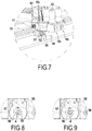
- these detection sensors 55 are made by contact sensors as illustrated in FIGS. Fig. 8 and 9 .
- each pivot axis 4 connected to an orientation motor 14 is provided with a cam 56 having two defined angular sectors 57, 58 , one of which 57 acts on the contact of the sensor ( Fig. 8 ) and the other 58 does not act on contact ( Fig. 9 ).
- the cam 56 is positioned to detect the passage from one sector 57 to the other 58 corresponding to a given position of the blades for example erected.
- the direction of rotation can be identified by determining the direction of passage from one sector to another.
- the installation 1 also comprises a control device, not shown, connected to the position and displacement sensors 50 , to the displacement motors 12 and to the orientation motors 14 making it possible to move in translation at least a part blades 3 and guide said translated blades.
- a control device thus makes it possible to control the operation of the displacement motors 12 and the orientation motors 14 so as to cover and to discover one or more areas of the surface 2 either on demand or as a function of pre-recorded programs .
- the control device preferably comprises a control box and power supply remote from the installation and connected to electronic circuits 61 embedded on the carriages 10 1 , 10 2 .
- This control device preferably comprises a remote control for remotely controlling the installation according to the invention.
- control device comprises a calibration mode allowing the installation to position the blades 3 in a defined position in order to locate their position.
- the pilot control system before any first use, the motors 12, 14 to place the various blades 3 in the stowed position with an erect orientation. The positioning of the blades 3 in the stowed position is ensured by the contact sensors 51.
- the control device has several prerecorded modes of use each corresponding to a type of positioning of the blades.
- it may be provided to pre-register a total coverage mode of the surface 2 or a partial coverage mode.
- it may be provided to pre-register the orientation of the blades is in the erect position or in the closed position, or in an intermediate position.
- the blades 3 are successively released from their stored position after a determined displacement step and until the blades occupy their desired exit position.
- the pitch of displacement of the blades corresponds to the spacing between two consecutive adjacent blades in horizontal position.
- the displacement motors 12 of the first blade 3 are controlled to ensure the translation in the direction F of the carriages 10 1 and 10 2 of the first blade 3 .
- the displacement motors 12 of the second blade are driven to ensure the translation in the direction F of the carriages 10 1 and 10 2 of the second blade 3.
- the control device thus drives the displacement motors 12 associated with the blades 3 to be deployed.
- the control device stops the operation of the displacement motors 12 when the blades 3 occupy their desired deployed position.
- the stop of operation of the displacement motors 12 is ensured either directly by the user according to his choice of deployment of the blades or according to a prerecorded program providing for the positioning of the blades 3 in defined positions provided by the measuring sensors of the rotation of displacement motors 12.
- control device can control the opening motors 14 to orient the blades 3.
- control device controls the operation of the orientation motors 14 only if the blades 3 occupy a fixed position different from the stored position.
- the control device For storage of the blades 3, the control device drives the orientation motors 14 of the deployed blades to position the latter in the erect position. When the deployed blades 3 occupy their upright position, the control device simultaneously drives the displacement motors 12 of these blades to bring them successively in their stored position detected by the position sensors 51.
- the control device can thus selectively drive the displacement motors 12 and orientation 14 of the blades to cover all or part of the surface 2, with blades erect, closed or intermediate position. It should be noted that the blades 3 are translated only in erect position.
Landscapes
- Engineering & Computer Science (AREA)
- Architecture (AREA)
- Civil Engineering (AREA)
- Structural Engineering (AREA)
- Physics & Mathematics (AREA)
- Electromagnetism (AREA)
- Power-Operated Mechanisms For Wings (AREA)
- Blinds (AREA)
- Operating, Guiding And Securing Of Roll- Type Closing Members (AREA)
Description
La présente invention concerne le domaine technique des installations pour couvrir et découvrir une surface à l'aide de lames orientables s'étendant parallèlement les unes aux autres afin de constituer un écran de protection ou de fermeture d'une surface au sens général, ces lames orientables présentant la possibilité en position déployée par rapport à la surface, de s'ouvrir ou de se fermer en fonction notamment des conditions climatiques.The present invention relates to the technical field of installations for covering and uncovering a surface using steerable blades extending parallel to each other in order to constitute a protective or closure screen of a surface in the general sense, these blades steerable having the possibility in the deployed position relative to the surface, to open or close according to particular weather conditions.
L'objet de l'invention vise de nombreuses applications pour constituer en particulier une couverture d'un toit faisant partie de pergolas ou de terrasses par exemple, ou un écran de protection pour des portes ou des fenêtres.The object of the invention is for many applications to constitute in particular a roof covering part of pergolas or terraces for example, or a protective screen for doors or windows.
Dans l'état de la technique, il est connu, par exemple par le document
Par rapport à une toiture fixe qui permet seulement de protéger un espace de la pluie et du soleil, ce toit ouvrable offre aussi la possibilité de contrôler, à volonté, l'aération et l'ensoleillement de l'espace équipé d'un tel toit Ce toit ouvrable présente toutefois l'inconvénient de laisser subsister en permanence les lames orientables au-dessus de la surface à couvrir, ce qui peut représenter un inconvénient lors notamment d'une longue période de non ensoleillement.Compared to a fixed roof that only protects a space from the rain and the sun, this roof also offers the possibility to control, at will, the ventilation and sunshine of the space equipped with such a roof This openable roof however has the disadvantage of leaving permanently blades orientable above the surface to be covered, which can be a disadvantage especially during a long period of no sun.
Pour remédier à ce problème, il est connu dans le domaine des volets de fermeture, par le brevet
Chaque mécanisme d'orientation et de déplacement comporte d'une part, une chaîne ou une courroie externe montée sans fin entre des poulies fixes de renvoi et présentant un brin extérieur et un brin intérieur, et d'autre part, une courroie interne monté sans fin entre des poulies fixes de renvoi et présentant un brin extérieur et un brin intérieur qui s'étend en vis-à-vis du brin intérieur de la courroie externe pour délimiter entre eux un couloir d'entraînement pour les lames. Chaque mécanisme d'orientation et de déplacement comporte un système de motorisation synchronisée des courroies externes et un système de motorisation synchronisée des courroies internes. La motorisation des systèmes de motorisation est commandée pour d'une part, déplacer dans le même sens les brins intérieurs pour déplacer en translation les lames dans le couloir d'entraînement et, d'autre part, déplacer les brins intérieurs selon des sens inversés pour orienter les lames.Each orientation and displacement mechanism comprises, on the one hand, an endless chain or belt mounted endlessly between fixed return pulleys and having an outer and an inner side, and on the other hand, an internal belt mounted without end between fixed return pulleys and having an outer strand and an inner strand which extends vis-à-vis the inner strand of the outer belt to delimit between them a drive corridor for the blades. Each orientation and displacement mechanism comprises a synchronized motorization system of the external belts and a synchronized motorization system of the internal belts. The motorization of the motorization systems is controlled for, on the one hand, moving in the same direction the inner strands to move the blades in translation in the drive lane and, on the other hand, move the inner strands in reverse directions to orient the blades.
Chaque mécanisme d'orientation et de déplacement comporte un dispositif de distribution des lames entraîné par les systèmes de motorisation synchronisée des courroies et adapté pour, selon un sens de déplacement des brins, engager successivement selon un pas d'écartement constant, les lames dans le couloir d'entraînement et, selon un sens de déplacement contraire, dégager successivement les lames du couloir d'entraînement afin qu'elles occupent leur position rangée.Each orientation and displacement mechanism comprises a blade distribution device driven by the synchronized motorization systems of the belts and adapted to, in a direction of movement of the strands, successively engage in a constant spacing pitch, the blades in the driving lane and, in a direction of opposite movement, successively clear the blades of the drive lane so that they occupy their stored position.
Cette installation n'est pas conçue pour constituer un toit et s'avère en pratique inadaptée à couvrir une relativement grande ouverture. Un autre inconvénient d'une telle installation concerne la nécessité de prévoir un magasin de stockage des lames. Ce magasin de stockage est aménagé soit pour empiéter sur la surface à couvrir ou soit dans le prolongement de la surface à couvrir si un emplacement est disponible à cet effet.This installation is not designed to be a roof and is in practice unsuitable to cover a relatively large opening. Another disadvantage of such an installation is the need to provide a blade storage magazine. This storage warehouse is arranged either to encroach on the surface to be covered or in the extension of the surface to be covered if a location is available for this purpose.
Le brevet
Un inconvénient de cette solution est la présence d'un magasin de stockage dans lequel les lames ne peuvent pas être orientées. De plus, cette solution est complexe et coûteuse à réaliser en raison du recours à des vis de grandes longueurs et de la précision requise en particulier pour le changement de guidage entre la glissière et la crémaillère. Cette solution s'avère en pratique irréalisable pour l'occultation d'une grande ouverture.A disadvantage of this solution is the presence of a storage magazine in which the blades can not be oriented. In addition, this solution is complex and expensive to achieve due to the use of screws of great lengths and the required accuracy especially for the change of guiding between the slide and the rack. This solution proves in practice impracticable for the occultation of a large opening.
La demande de brevet
Cette installation s'avère complexe et couteuse à réaliser en raison de la mise en oeuvre de tiges filetées et du degré de précision requis pour son montage. Une telle installation ne se trouve pas adaptée pour couvrir une surface de grande dimension.This installation is complex and expensive to implement because of the implementation of threaded rods and the degree of precision required for its assembly. Such an installation is not suitable for covering a large area.
La demande de brevet
La présente invention vise à remédier aux inconvénients de l'art antérieur en proposant une installation de conception simple et peu onéreuse pour couvrir et découvrir, à l'aide de lames orientables, une surface aussi bien verticale qu'horizontale qui présente des dimensions variables dans une large gamme pouvant atteindre de grandes dimensions.The present invention aims to overcome the drawbacks of the prior art by proposing a simple and inexpensive installation to cover and discover, with the aid of steerable blades, a vertical as well as horizontal surface which has variable dimensions in a wide range that can reach large dimensions.
La présente invention vise à proposer une installation complètement modulable permettant de s'adapter facilement aux dimensions de la surface à couvrir, tout en offrant l'avantage de pouvoir orienter à volonté les lames de diverses zones de la surface dans des positions différentes.The present invention aims to provide a completely modular installation for easily adapting to the dimensions of the surface to be covered, while offering the advantage of being able to guide at will the blades of various areas of the surface in different positions.
Un autre objet de l'invention vise à proposer une installation ne nécessitant pas de dédier un espace au stockage des lames en position repliée.Another object of the invention is to propose an installation that does not require dedicating a space for storing the blades in the folded position.
Pour atteindre un tel objectif, l'installation pour couvrir et découvrir à l'aide de lames orientables, une surface délimitée par une structure porteuse, comporte :
- une série de lames orientables s'étendant parallèlement les unes aux autres selon leurs bords longitudinaux et équipées à chacune de leurs bords d'extrémités, d'un axe de pivotement ;
- un système d'orientation des lames adapté pour assurer le pivotement d'au moins certaines des lames afin que les bords longitudinaux des lames soient jointifs ou non jointifs pour respectivement fermer ou ouvrir la surface correspondante ;
- un système de déplacement des lames entre une position rangée dans laquelle les lames sont accolées les unes aux autres et une position déployée dans laquelle au moins une partie des lames sont déployées en regard de la surface ;
- deux voies de guidage en translation des lames, aménagées sur la structure porteuse en étant disposées parallèlement l'une à l'autre selon deux côtés opposés de la surface.
- a series of steerable blades extending parallel to each other along their longitudinal edges and equipped at each of their end edges with a pivot axis;
- a blade orientation system adapted to pivot at least some of the blades so that the longitudinal edges of the blades are contiguous or not contiguous to respectively close or open the corresponding surface;
- a system for moving the blades between a stowed position in which the blades are contiguous to each other and an extended position in which at least a portion of the blades are deployed facing the surface;
- two guideways in translation of the blades, arranged on the support structure being arranged parallel to one another on two opposite sides of the surface.
Selon l'invention :
- chaque lame est supportée par ses axes de pivotement à l'aide d'un jeu de deux chariots guidés en translation selon les voies de guidage ;
- le système de déplacement comporte, pour chaque paire de chariots équipant une lame, deux moteurs de déplacement embarqués l'un dans un premier chariot et l'autre dans un deuxième chariot et entraînant chacun en rotation un pignon d'entraînement en translation de l'axe de pivotement de la lame, le pignon coopérant avec une crémaillère montée sur la structure porteuse selon une direction parallèle à la voie de guidage ;
- le système d'orientation comporte, pour chaque paire de chariots équipant une lame, au moins un moteur d'orientation embarqué dans au moins l'un desdits chariots et relié angulairement avec l'axe de pivotement ;
- des capteurs de position et de déplacement des lames ;
- et un dispositif de commande relié aux capteurs, aux moteurs de déplacement et aux moteurs d'orientation, pour déplacer en translation au moins une partie des lames et orienter lesdites lames translatées.
- each blade is supported by its pivot axes with a set of two trolleys guided in translation along the guide tracks;
- the displacement system comprises, for each pair of carriages equipping a blade, two displacement motors on board one in a first carriage and the other in a second carriage and each rotating a drive gear in translation of the pivot axis of the blade, the pinion cooperating with a rack mounted on the supporting structure in a direction parallel to the guide path;
- the orientation system comprises, for each pair of trolleys equipping a blade, at least one orientation motor embedded in at least one of said trolleys and angularly connected with the pivot axis;
- position and displacement sensors of the blades;
- and a control device connected to the sensors, the displacement motors and the orientation motors, for translating at least a portion of the blades and orienting said translated blades.
De plus, l'installation selon l'invention peut présenter en outre en combinaison au moins l'une et/ou l'autre des caractéristiques additionnelles suivantes :
- le système d'orientation comporte pour chaque lame, un moteur d'orientation monté sur l'un des chariots équipant ladite lame ;
- les chariots munis d'un moteur de déplacement et d'un moteur d'orientation d'une part, et les chariots munis d'un moteur de déplacement d'autre part sont montés de façon alternée d'une lame à l'autre, selon chaque côté de la surface à couvrir ou à découvrir ;
- chaque chariot équipé d'un moteur de déplacement présente un corps principal de support pour le moteur de déplacement, ce corps principal étant pourvu d'un système de guidage en rotation pour l'axe de pivotement de la lame, engagé librement dans un logement aménagé dans la lame, l'axe de de pivotement étant pourvu du pignon et entraîné en rotation par le moteur de déplacement ;
- chaque chariot équipé d'un moteur de déplacement et d'un moteur d'orientation comporte un corps principal de support pour le moteur de déplacement et le moteur d'orientation, le corps principal étant pourvu d'un système de guidage en rotation d'un arbre tubulaire équipé du pignon et entraîné en rotation par le moteur en déplacement, l'axe de pivotement étant monté à l'intérieur de l'arbre tubulaire en étant entraîné en rotation par le moteur d'orientation et monté solidaire en rotation de la lame ;
- chaque chariot comporte un corps principal relié par un axe de liaison démontable, à un palier de guidage coopérant avec une voie de guidage ;
- chaque crémaillère est réalisée par une courroie crantée fixée sur la structure porteuse ;
- les capteurs de position et de déplacement des lames comportent des capteurs de contact montés sur les chariots d'une voie de guidage pour être actionnés par le chariot situé en amont dans le sens de sortie des lames ou par la structure porteuse pour le chariot de la dernière lame dans le sens de sortie ;
- les capteurs de position et de déplacement des lames comportent des capteurs de mesure de la rotation des moteurs de déplacement et de la rotation des moteurs d'orientation ainsi que des capteurs de détection du sens d'orientation des lames ;
- le dispositif de commande comporte un mode d'étalonnage et plusieurs modes d'utilisation préenregistrés correspondant chacun à un type de positionnement des lames ;
- le dispositif de commande pilote le fonctionnement des moteurs de déplacement et d'orientation de manière que préalablement à la commande en déplacement d'une lame, le dispositif de commande pilote le moteur d'orientation de ladite lame pour la placer en position verticale si elle n'occupe pas cette position verticale ;
- pour un mode d'utilisation consistant en la sortie d'un nombre déterminé de lames de leur position rangée, le dispositif de commande pilote le fonctionnement des moteurs de déplacement des lames à déployer, de manière qu'à chaque fois que la première lame est avancée d'un pas, la lame située en amont est commandée en déplacement, les moteurs de déplacement des lames étant commandés jusqu'à ce que les lames occupent leur position de sortie ;
- le dispositif de commande pilote les moteurs de déplacement de manière que le pas de déplacement des lames corresponde à l'écartement entre deux lames consécutives jointives en position horizontale ;
- le dispositif de commande pilote le fonctionnement des moteurs d'orientation uniquement si la lame occupe une position fixe différente de la position rangée.
- the orientation system comprises for each blade, an orientation motor mounted on one of the carriages equipping said blade;
- the carriages equipped with a displacement motor and an orientation motor on the one hand, and the carriages provided with a displacement motor on the other hand are mounted alternately from one blade to the other, on each side of the surface to be covered or uncovered;
- each carriage equipped with a displacement motor has a main support body for the displacement motor, this main body being provided with a rotation guide system for the axis of pivoting of the blade, freely engaged in a fitted housing in the blade, the axis pivoting means being provided with the pinion and rotated by the displacement motor;
- each carriage equipped with a displacement motor and an orientation motor comprises a main support body for the displacement motor and the orientation motor, the main body being provided with a rotation guide system of a tubular shaft equipped with the pinion and rotated by the motor in displacement, the pivot axis being mounted inside the tubular shaft being rotated by the orientation motor and mounted integral in rotation with the blade;
- each carriage comprises a main body connected by a detachable connecting pin, to a guide bearing cooperating with a guide path;
- each rack is made by a toothed belt attached to the supporting structure;
- the position and displacement sensors of the blades comprise contact sensors mounted on the carriages of a guideway to be actuated by the carriage situated upstream in the direction of exit of the blades or by the carrying structure for the carriage of the last blade in the exit direction;
- the position and displacement sensors of the blades comprise sensors for measuring the rotation of the displacement motors and the rotation of the orientation motors as well as sensors for detecting the direction of orientation of the blades;
- the control device comprises a calibration mode and several pre-recorded use modes each corresponding to a type of positioning of the blades;
- the control device controls the operation of the displacement and orientation motors in such a way that prior to the control in displacement of a blade, the control device controls the motor of orientation of said blade to place it in a vertical position if it does not occupy this vertical position;
- for a mode of use consisting in the output of a determined number of blades from their stored position, the control device controls the operation of the displacement motors of the blades to be deployed, so that each time the first blade is advanced one step, the blade upstream is controlled in displacement, the blade moving motors being controlled until the blades occupy their output position;
- the control device drives the displacement motors so that the displacement pitch of the blades corresponds to the distance between two consecutive blades contiguous in horizontal position;
- the control device controls the operation of the orientation motors only if the blade occupies a fixed position different from the stored position.
Diverses autres caractéristiques ressortent de la description faite ci-dessous en référence aux dessins annexés qui montrent, à titre d'exemples non limitatifs, des formes de réalisation de l'objet de l'invention.
- La
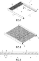
Figure 1 est une vue en perspective d'un exemple de réalisation d'une installation conforme à l'invention dans lequel les lames sont toutes rangées en position dressée. - La
Figure 2 est une vue en perspective d'un exemple de réalisation d'une installation conforme à l'invention dans lequel les lames sont toutes déployées avec une partie en position jointive. - La
Figure 3 est une vue en coupe de l'installation illustrée à laFig. 2 et montrant la position de pivotement des lames en position déployée. - La
Figure 4 est une vue éclatée en perspective montrant plus précisément le montage d'une lame faisant partie d'une installation conforme à l'invention. - La
Figure 5 est une vue en coupe élévation montrant le montage d'une lame. - La
Figure 6 est une vue à grande échelle montrant la réalisation d'un chariot pourvu d'un moteur de déplacement et d'un moteur d'orientation. - La
Figure 7 est une vue en perspective partielle montrant trois lames placées en position rangée. - Les
Figures 8 et 9 sont des vues montrant un exemple de réalisation de capteurs de position de l'orientation des lames.
- The
Figure 1 is a perspective view of an exemplary embodiment of an installation according to the invention in which the blades are all arranged in erect position. - The
Figure 2 is a perspective view of an exemplary embodiment of an installation according to the invention wherein the blades are all deployed with a portion in contiguous position. - The
Figure 3 is a sectional view of the installation illustrated in theFig. 2 and showing the pivoting position of the blades in the deployed position. - The
Figure 4 is an exploded perspective view showing more precisely the mounting of a blade forming part of an installation according to the invention. - The
Figure 5 is a sectional elevation view showing the mounting of a blade. - The
Figure 6 is a large-scale view showing the realization of a carriage provided with a displacement motor and an orientation motor. - The
Figure 7 is a partial perspective view showing three blades placed in a stowed position. - The
Figures 8 and 9 are views showing an exemplary embodiment of position sensors of the orientation of the blades.
Tel que cela ressort plus précisément des
Les lames 3 sont pourvues à chacun de leurs bords d'extrémité, d'un axe de pivotement 4 pour permettre en particulier leur orientation. L'installation 1 comporte un mécanisme I d'orientation des lames 3 selon leur axe de pivotement 4 afin d'assurer le pivotement d'au moins certaines et d'une manière générale de l'ensemble des lames 3 afin que les bords longitudinaux 31, 32 des lames voisines soient jointifs pour fermer la surface correspondante ou soient non jointifs pour ouvrir la surface 2. The
Comme cela ressort des
L'installation selon l'invention comporte également un système de déplacement II des lames 3 entre une position rangée (
Les systèmes I et II assurent le déplacement et l'orientation des lames 3 de manière à ce qu'elles forment ensemble au moins un écran de protection s'ouvrant et se fermant à volonté. En fonction des applications visées, cet écran forme un toit ou un volet de protection pouvant couvrir totalement la surface 2 ou une partie seulement de la surface 2, avec possibilité d'orientation des lames à la demande lorsque les lames ne sont pas en position rangée.The systems I and II ensure the displacement and orientation of the
L'installation 1 comporte également deux voies de guidage 8 assurant le guidage en translation pour les lames 3 entre une position rangée dans laquelle les lames sont accolées les unes aux autres (
Les voies de guidage 8 sont aménagées sur la structure porteuse du bâti 5 réalisé de toute manière appropriée en fonction des applications visées et venant entourer la surface 2 à couvrir pour former avantageusement un cadre.The
Cette structure porteuse 5 comporte avantageusement deux profilés longitudinaux 52 et 53 s'étendant parallèlement entre eux selon deux côtés opposés de la surface 2 et parallèlement aux voies de guidage 8. Ces deux profilés longitudinaux 52 et 53 sont reliés entre eux à leur extrémité, par des profilés de liaison 51 et 54 (non représentés) formant ensemble un cadre délimitant la surface 2. L'un des profilés de liaison 54 délimite le bord de butée pour le bord longitudinal 31 de la première lame tandis que l'autre profilé 51 , délimite le bord de rangement pour le bord longitudinal de la dernière lame 3. La première lame et la dernière lame sont prises en considération du sens de déploiement des lames représenté par la flèche F pour lequel les lames passent de la position rangée à la position déployée. Lors du reploiement des lames 3 selon le sens F1 opposé au sens F, les premières et dernières lames sont considérées être les même que celles désignées lors de l'opération de déploiement.This supporting
L'installation 1 selon l'invention est destinée à être fixée par tout moyen approprié sur une structure porteuse non représentée adaptée à l'application visée. Dans le cas où l'installation 1 selon l'invention est destinée à former le toit d'une pergola par exemple, la structure porteuse 5 comporte des poteaux supportant le cadre formé par les profilés de liaison et les profilés longitudinaux.The installation 1 according to the invention is intended to be fixed by any appropriate means on a carrier structure not shown adapted to the intended application. In the case where the installation 1 according to the invention is intended to form the roof of a pergola for example, the supporting
Conformément à l'invention, chaque lame 3 est supportée à chacune de ses extrémités plus précisément par ses axes de pivotement 4, par un jeu de deux chariots 101 , 102 guidés en translation selon les voies de guidage 8. Tel que cela ressort plus précisément des
Conformément à l'invention le système de déplacement II comporte pour chaque paire de chariots 101 , 102 équipant une lame, avantageusement deux moteurs de déplacement 12 embarqués chacun sur un chariot. Il doit être compris que chaque lame 3 est motorisée par deux moteurs pour équilibrer les efforts appliqués aux lames 3. Par exemple, les moteurs de déplacement 12 sont des moteurs électriques par exemple à courant continu à balais, reliés à une source d'alimentation électrique par l'intermédiaire de câbles de raccordements non représentés.According to the invention the displacement system II comprises for each pair of carriages 10 1 , 10 2 equipping a blade, preferably two
Il ressort de la description qui précède que les lames 3 sont automotrices et peuvent être déplacées indépendamment les unes des autres. Selon une caractéristique de l'invention, chaque lame 3 peut également être orientée individuellement. Ainsi, le système d'orientation I comporte pour chaque paire de chariot équipant une lame, au moins un et dans l'exemple illustré, un unique moteur d'orientation 14 embarqué sur l'un des deux chariots 101 et 102 équipant une lame 3. Chaque moteur d'orientation 14 est relié angulairement avec un axe de pivotement 4 pour placer la lame 3 dans une position angulaire déterminée dressée (perpendiculaire de la surface 2 à savoir verticale dans le cas d'une pergola), de fermeture (en position horizontale) ou intermédiaire prise entre ces deux positions verticale et horizontale.It follows from the above description that the
Selon l'exemple préféré de réalisation illustré sur les dessins, chaque lame 3 est donc supportée, à l'une de ses extrémités, par un premier chariot 101 embarquant uniquement un moteur de déplacement 12 et, à son extrémité opposée, par un deuxième chariot 102 embarquant un moteur de déplacement 12 et un moteur d'orientation 14. Les chariots 102 munis d'un moteur de déplacement 12 et d'un moteur d'orientation 14 d'une part et les chariots 101 munis d'un moteur de déplacement 12 d'autre part sont montés de façon alternée d'une lame à l'autre selon chaque côté de la surface 2 à couvrir ou à découvrir. En d'autres termes, les premiers et seconds chariots sont montés alternativement selon chaque côté longitudinaux de la structure porteuse. Une telle disposition permet de gagner en encombrement notamment en position rangée comme cela sera expliqué dans la suite de la description.According to the preferred embodiment illustrated in the drawings, each
Chaque chariot 101 , 102 présente un corps principal 15 de forme générale parallélépipédique allongée s'étendant principalement selon l'axe de pivotement 4. De préférence, les corps 15 des premiers et seconds chariots ne sont pas identiques pour justement gagner en encombrement en position rangée. Tel que cela ressort plus précisément des
Bien entendu, chaque moteur de déplacement 12 est monté de toute manière appropriée sur le corps principal 15 de chaque chariot 101 , 102 . Chaque moteur de déplacement 12 entraine en rotation un pignon 17 entraînant en translation une lame 3. Chaque pignon 17 coopère avec une crémaillère 18 montée sur la structure porteuse 5 selon une direction parallèle à la voie de guidage 8 et selon toute la longueur de la voie de guidage pour permettre la translation des lames entre leurs positions rangée et déployée. Selon une variante avantageuse de réalisation, chaque crémaillère 18 est réalisée par une courroie crantée fixée sur la structure porteuse 5. Of course, each
Dans l'exemple de réalisation illustré sur les dessins (
Selon une caractéristique de l'invention, chaque profilé longitudinal 52 , 53 est réalisé par extrusion. Les profilés peuvent être assemblés bout à bout à volonté pour s'adapter aux dimensions de la surface 2 à couvrir. Avantageusement, la cloison médiane 5a et l'aile interne 5d délimitent entre eux une gouttière 5e à l'aplomb de laquelle s'étendent les bords d'extrémité des lames pour récupérer éventuellement l'eau de pluie.According to one characteristic of the invention, each
Les profilés longitudinaux 52 , 53 qui sont ouverts peuvent être avantageusement fermés à l'aide d'un couvercle 19 venant protéger les chariots et montés entre l'aile externe 5 et la cloison médiane 5a. Ce couvercle 19 est pourvu de brosses 191 (
Avantageusement, chaque palier de guidage 11 est relié au corps principal 15 des chariots 101, 102 par l'intermédiaire d'un axe de liaison 20 à caractère de préférence démontable. Tel que cela ressort plus précisément de la
Avantageusement, un ressort 23 est engagé sur l'axe de liaison 20 et interposé entre le corps principal 15 et le palier de guidage 11 pour compenser les tolérances de fabrication et de montage.Advantageously, a
La
Les
La rotation de l'arbre tubulaire 42 conduit à la translation du chariot 102 entraînant la translation de la lame dont l'axe de pivotement 4 est poussé lors de la translation du chariot. Chaque pignon 17 coopère indirectement avec un axe de pivotement 4 pour entrainer en translation l'axe de pivotement 4 de la lame 3, par la liaison pivot réalisée entre l'arbre tubulaire 42 et l'axe de pivotement 4. The rotation of the
Par ailleurs, l'axe de pivotement 4 est entraîné en rotation par le moteur d'orientation 14 dont l'arbre de sortie coopère avec une roue dentée 47 calée en rotation avec l'axe de pivotement 4 dont l'extrémité opposée est engagée à l'intérieur du logement 32 et liée angulairement à la lame à l'aide par exemple de goupilles de liaison 48. L'axe de pivotement 4 est ainsi monté libre en rotation à l'intérieur de l'arbre tubulaire 42 et peut être orienté à volonté dans une position stable déterminée à l'aide du moteur d'orientation 14. Furthermore, the
L'installation 1 comporte également des capteurs 50 de position et de déplacement des lames 3. De tels capteurs 50 permettent de connaître la position de chacune des lames 3 à tout moment tout au long de leur parcours sur la voie de guidage. De tels capteurs 50 de position de déplacement peuvent être réalisés de toute manière appropriée.The installation 1 also comprises
Dans l'exemple illustré et tel que cela ressort plus précisément de la
Les capteurs de position et de déplacement 50 comportent également des capteurs de mesure de la rotation des moteurs d'orientation 14 permettant de pouvoir connaître l'orientation angulaire des lames 3. Les capteurs de position et de déplacement 50 comportent également des capteurs 55 de détection du sens d'orientation des lames. Par exemple, ces capteurs de détection 55 sont réalisés par des capteurs de contact comme illustré aux
L'installation 1 selon l'invention comporte également un dispositif de commande non représenté, relié aux capteurs 50 de position et de déplacement, aux moteurs de déplacement 12 et aux moteurs d'orientation 14 permettant de déplacer en translation au moins une partie des lames 3 et d'orienter lesdites lames translatées. Un tel dispositif de commande permet ainsi de piloter le fonctionnement des moteurs de déplacement 12 et des moteurs d'orientation 14 de manière à permettre de couvrir et de découvrir une ou plusieurs zones de la surface 2 soit à la demande soit en fonction de programmes préenregistrés. Le dispositif de commande comporte de préférence un boitier de commande et d'alimentation déportée par rapport à l'installation et reliée à des circuits électroniques 61 embarqués sur les chariots 101, 102 . Ce dispositif de commande comporte de préférence une télécommande permettant de piloter à distance l'installation conforme à l'invention.The installation 1 according to the invention also comprises a control device, not shown, connected to the position and
Bien entendu, le dispositif de commande comporte un mode d'étalonnage permettant à l'installation de positionner les lames 3 dans une position définie afin de repérer leur position. D'une manière générale, le système de commande pilote avant toute première utilisation, les moteurs 12, 14 afin de placer les différentes lames 3 en position rangée avec une orientation dressée. Le repérage de la position des lames 3 en position rangée est assuré par les capteurs de contact 51. Of course, the control device comprises a calibration mode allowing the installation to position the
De préférence, le dispositif de commande présente plusieurs modes d'utilisation préenregistrés correspondant chacun à un type de positionnement des lames. Ainsi, il peut être prévu de préenregistrer un mode de couverture total de la surface 2 ou un mode de couverture partielle. De même, il peut être prévu de préenregistrer l'orientation des lames soit en position dressée soit en position de fermeture, soit dans une position intermédiaire.Preferably, the control device has several prerecorded modes of use each corresponding to a type of positioning of the blades. Thus, it may be provided to pre-register a total coverage mode of the
Pour couvrir la surface 2, les lames 3 sont sorties successivement de leur position rangée après un pas de déplacement déterminé et jusqu'à ce que les lames occupent leur position de sortie souhaitée. Avantageusement, le pas de déplacement des lames correspond à l'écartement entre deux lames consécutives jointives en position horizontale.To cover the
Ainsi, les moteurs de déplacement 12 de la première lame 3 sont commandés pour assurer la translation selon le sens F des chariots 101 et 102 de cette première lame 3. Lorsque cette première lame 3 a été déplacée d'un pas donné, les moteurs de déplacement 12 de la deuxième lame sont pilotés pour assurer la translation selon le sens F des chariots 101 et 102 de cette deuxième lame 3. Thus, the
Le dispositif de commande pilote ainsi les moteurs de déplacement 12 associés aux lames 3 devant être déployées. Le dispositif de commande arrête le fonctionnement des moteurs de déplacement 12 lorsque les lames 3 occupent leur position déployée souhaitée. L'arrêt de fonctionnement des moteurs de déplacement 12 est assuré soit directement par l'utilisateur en fonction de son choix de déploiement des lames soit selon un programme préenregistré prévoyant le positionnement des lames 3 en des positions définies assurées par les capteurs de mesure de la rotation des moteurs de déplacement 12. The control device thus drives the
Lorsque les lames 3 déployées occupent une position fixe, le dispositif de commande peut piloter les moteurs d'ouverture 14 pour orienter les lames 3. When the deployed
Il est à noter que le dispositif de commande pilote le fonctionnement des moteurs d'orientation 14 uniquement si les lames 3 occupent une position fixe différente de la position rangée.It should be noted that the control device controls the operation of the
Pour le rangement des lames 3, le dispositif de commande pilote les moteurs d'orientation 14 des lames déployées pour positionner ces dernières en position dressée. Lorsque les lames déployées 3 occupent leur position dressée, le dispositif de commande pilote simultanément les moteurs de déplacement 12 de ces lames pour les amener successivement dans leur position rangée détectée par les capteurs de position 51. For storage of the
Le dispositif de commande peut ainsi piloter sélectivement les moteurs de déplacement 12 et d'orientation 14 des lames pour couvrir toute ou partie de la surface 2, avec des lames en position dressée, fermée ou intermédiaire. Il est à noter que les lames 3 sont translatées uniquement en position dressée.The control device can thus selectively drive the
Claims (14)
- A unit for covering and uncovering a surface (2) delimited by a bearing structure (5) using adjustable slats (3), the unit comprising:- a series of adjustable slats (3) extending mutually parallel along their longitudinal edges and equipped at each of their end edges with a pivot pin (4);- a system (I) for orientating the slats (3) suitable for pivoting at least some of the slats so that the longitudinal edges of the slats are contiguous or non-contiguous to respectively close or open the related surface;- a system (II) for moving the slats (3) between a retracted position wherein the slats are side-by-side and a deployed position wherein at least a part of the slats are deployed with regard to the surface;- two tracks (8) for guiding the slats in translation, formed on the bearing structure (5) while being arranged mutually parallel along two opposite sides of the surface;- each slat (3) is supported by its pivot pins (4) using a set of two carriages (101, 102 ) guided in translation along the guide tracks (8);- the orientation system (I) comprises, for each carriage pair equipping a slat, at least one orientation motor (14) being mounted in at least one of the carriages and angularly linked with the pivot pin;- position and slat (3) movement sensors (50);- and a control device linked to the sensors (50), the movement motors (12) and the orientation motors (14), for moving at least part of the slats in translation and orientating said slats,characterized in that the movement system (II) comprises, for each carriage pair (101 , 102 ) equipping a slat, two movement motors (12) one being mounted in a first carriage (101 ) and the other in a second carriage (102 ) and each rotationally driving a pinion (17) engaging with a rack (18) assembled on the bearing structure along a direction parallel to the guide track, each pinion (17) engaging with a pivot pin (4) for driving the pivot pin (4) of the slat (3) in translation.
- The unit according to claim 1, characterized in that the orientation system (I) comprises for each slat (3), an orientation motor (14) being mounted in the second carriage (102 ) equipping said slat.
- The unit according to claim 2, characterized in that the second carriages (102 ) provided with a movement motor (12) and an orientation motor (14) on the one hand, and the first carriages (101 ) provided with a movement motor (12) on the other hand, are assembled alternately from one slat to the next, along each side of the surface to be covered or uncovered.
- The unit according to one of claims 1 to 3, characterized in that each first carriage (101 ) equipped with a movement motor (12) has a main support body (15) for the movement motor, this main body being provided with a rotational guide system (31) for the pivot pin (4) of the slat, freely engaged in a housing (32) formed in the slat, the pivot pin (4) being provided with the pinion (17) and rotationally driven by the movement motor (12).
- The unit according to one of claims 1 to 4, characterized in that each second carriage (102 ) equipped with a movement motor (12) and an orientation motor (14) comprises a main support body (15) for the movement motor and the orientation motor, the main body (15) being provided with a system (41) for rotationally guiding a tubular shaft (42) equipped with the pinion and rotationally driven by the movement motor, the pivot pin (4) being assembled inside the tubular shaft (42) while being rotationally driven by the orientation motor (14) and assembled to rotate with the slat as a single part.
- The unit according to claims 4 or 5, characterized in that each carriage (101 , 102 ) comprises a main body linked by a removable link pin (20) to a guide bearing (11) engaging with a guide track (8).
- The unit according to one of claims 1 to 6, characterized in that each rack (18) is formed by a toothed belt attached to the bearing structure (5).
- The unit according to one of claims 1 to 7, characterized in that the position and slat movement sensors (50) comprise contact sensors (51) assembled on the carriages of a guide track to be actuated by the carriage located ahead in the direction of extension of the slats or by the bearing structure for the carriage of the last slat in the direction of extension.
- The unit according to one of claims 1 to 8, characterized in that the position and slat (3) movement sensors (50) comprise sensors for measuring the rotation of the movement motors and the rotation of the orientation motors as well as sensors for detecting the direction of orientation of the slats.
- The unit according to one of claims 1 to 9, characterized in that the control device comprises a calibration mode and several preset use modes each corresponding to a type of slat position.
- The unit according to one of claims 1 to 10, characterized in that the control device controls the operation of the movement (12) and orientation (14) motors in such a way that prior to the control to move a slat, the control device controls the orientation motor of said slat to place it in the vertical position if it is not occupying this vertical position.
- The unit according to one of claims 1 to 11, characterized in that for a use mode consisting in the extension of a determined number of slats from their retracted position, the control device controls the operation of the movement motors (12) of the slats to be deployed, in such a way that each time the first slat is advanced by one increment, the slat located upstream is controlled to move, the slat movement motors (12) being controlled until the slats are occupying their extended position.
- The unit according to claim 12, characterized in that the control device controls the movement motors (12) in such a way that the increment of movement of the slats corresponds to the separation between two consecutive slats contiguous in the horizontal position.
- The unit according to one of claims 1 to 13, characterized in that the control device controls the operation of the orientation motors (14) only if the slat is occupying a fixed position different from the retracted position.
Priority Applications (1)
| Application Number | Priority Date | Filing Date | Title |
|---|---|---|---|
| HRP20182127TT HRP20182127T1 (en) | 2014-10-15 | 2018-12-17 | Unit for covering and uncovering a surface using self-propelled adjustable slats |
Applications Claiming Priority (2)
| Application Number | Priority Date | Filing Date | Title |
|---|---|---|---|
| FR1459896A FR3027334B1 (en) | 2014-10-15 | 2014-10-15 | INSTALLATION FOR COVERING AND DISCOVERING A SURFACE USING AUTOMOTIVE ORIENTABLE BLADES |
| PCT/FR2015/052766 WO2016059344A1 (en) | 2014-10-15 | 2015-10-14 | Unit for covering and uncovering a surface using self-propelled adjustable slats |
Publications (2)
| Publication Number | Publication Date |
|---|---|
| EP3207190A1 EP3207190A1 (en) | 2017-08-23 |
| EP3207190B1 true EP3207190B1 (en) | 2018-10-03 |
Family
ID=53514211
Family Applications (1)
| Application Number | Title | Priority Date | Filing Date |
|---|---|---|---|
| EP15793866.3A Active EP3207190B1 (en) | 2014-10-15 | 2015-10-14 | Unit for covering and uncovering a surface using self-propelled adjustable slats |
Country Status (7)
| Country | Link |
|---|---|
| US (1) | US10280625B2 (en) |
| EP (1) | EP3207190B1 (en) |
| ES (1) | ES2703859T3 (en) |
| FR (1) | FR3027334B1 (en) |
| HR (1) | HRP20182127T1 (en) |
| PT (1) | PT3207190T (en) |
| WO (1) | WO2016059344A1 (en) |
Families Citing this family (19)
| Publication number | Priority date | Publication date | Assignee | Title |
|---|---|---|---|---|
| BE1022563B1 (en) * | 2014-10-16 | 2016-06-02 | Renson Sunprotection Screens Nv | LAMEL DEVICE |
| FR3035423B1 (en) * | 2015-04-24 | 2021-06-18 | Castel Jean Louis | MULTIFUNCTIONAL MODULAR OCCULTATION DEVICE, ESPECIALLY FOR PERGOLA |
| FR3042802B1 (en) * | 2015-10-26 | 2019-08-02 | Jean-Louis Castel | DEVICE FOR RECOVERING RAINWATER WATERS IN A PERGOLA WITH ORIENTABLE BLADES |
| FR3049976B1 (en) * | 2016-04-12 | 2022-08-05 | Biossun | INSTALLATION FOR COVERING AND UNVEILING A SURFACE USING ATTACHED SELF-PROPELLED SWIVEL BLADES |
| CN108166688B (en) | 2017-05-08 | 2019-11-05 | 宁波万汇休闲用品有限公司 | Cover paulin device |
| US10094122B1 (en) * | 2017-06-06 | 2018-10-09 | Optimal Tasarim Uygulama Ve Yapi Sistemleri San. Ve Tic. Anomim Sirketi | Automatic wide angle panel roof |
| FR3071271B1 (en) * | 2017-09-21 | 2020-11-06 | Accoplas Soc Gen De Fermetures | SLIDING AND MOTORIZED OBSTRUCTION DEVICE FOR FACADE OPENING |
| ES2969932T3 (en) * | 2017-10-30 | 2024-05-23 | Advanced Design Innovations Pty Ltd | Retractable roof/wall assembly |
| EP3495582A1 (en) | 2017-12-08 | 2019-06-12 | Activa Awning Inc. | Awning apparatus |
| CN109914715A (en) * | 2017-12-13 | 2019-06-21 | 上海兆泰电动科技有限公司 | It is a kind of to automatically control flexible canopy and its working principle |
| FR3075838B1 (en) * | 2017-12-27 | 2020-02-28 | Biossun | INSTALLATION WITH ADJUSTABLE BLADES INDEPENDENTLY FROM ONE ANOTHER |
| GR1010106B (en) * | 2018-09-20 | 2021-10-19 | Κωνσταντινος Παναγιωτη Σπηλιοπουλος | Method for the construction of moving roof shade system with louvers |
| IT201800011100A1 (en) * | 2018-12-14 | 2020-06-14 | Pratic F Lli Orioli S P A | GUIDING ELEMENT FOR ROOFING EQUIPMENT AND RELATIVE MOUNTING METHOD |
| IT201800011083A1 (en) * | 2018-12-14 | 2020-06-14 | Pratic F Lli Orioli S P A | MOBILE COVERING ELEMENT FOR A COVERING APPARATUS, PREFERABLY AN ADJUSTABLE TYPE SUNSCREEN |
| FR3093339B1 (en) | 2019-02-28 | 2021-03-05 | Biossun | Installation to cover a surface using orientable slats translated flat |
| US12037794B1 (en) * | 2019-11-18 | 2024-07-16 | Micah Rayburn | Louvered enclosure system |
| CN111758429B (en) * | 2020-06-04 | 2022-08-05 | 同济大学 | Multi-degree-of-freedom sun-shading three-dimensional greening device |
| BE1028903B1 (en) * | 2020-12-16 | 2022-07-19 | Skylux Nv | EXTRUDED GUTTER PROFILE AND SELF-SUPPORTING WINDOW ASSEMBLY |
| ES2978307A1 (en) * | 2023-01-31 | 2024-09-10 | Codeval Aluminium Sl | Folding slat guide system |
Family Cites Families (22)
| Publication number | Priority date | Publication date | Assignee | Title |
|---|---|---|---|---|
| FR1475733A (en) | 1966-01-12 | 1967-04-07 | Planet Usines | Improvements to shutters for windows and openings |
| CH613094A5 (en) * | 1976-06-22 | 1979-09-14 | Plascon Ag | |
| US4449563A (en) * | 1982-05-26 | 1984-05-22 | Rca Corporation | Counterbalance system for sagging rotating element |
| US4527355A (en) * | 1983-02-24 | 1985-07-09 | Zeon Kasei Co., Ltd. | Opening and closing type louver device |
| US5732507A (en) * | 1993-11-04 | 1998-03-31 | H.V. Aluminium Pty. Limited | Louvre assembly |
| AU694383B2 (en) | 1995-11-20 | 1998-07-16 | Louver Shield Pty Limited | Interclosing panel screen |
| US5873202A (en) * | 1997-07-07 | 1999-02-23 | Parks; Charles Sherman | Slidably adjustable rigid awning |
| US6202363B1 (en) * | 1998-06-08 | 2001-03-20 | Chao-Jen Chang | Shielding canopy |
| DE10125934C1 (en) * | 2001-05-28 | 2003-01-16 | Arthur Prib | Drive for adjusting several sun protection slats |
| IL154223A0 (en) | 2003-01-30 | 2003-07-31 | Parma Shutter Technologies Ltd | Door shutter mechanism |
| GB201007328D0 (en) * | 2010-05-04 | 2010-06-16 | Gray Matter Alpha Ltd | Lourve vane system |
| GB201102111D0 (en) * | 2011-02-08 | 2011-03-23 | Wjp Holdings Ltd | Thermal shutter system |
| US8857106B2 (en) * | 2011-05-09 | 2014-10-14 | Hunter Douglas Inc. | Shutter with field serviceable louvers |
| US8756873B1 (en) * | 2011-12-05 | 2014-06-24 | Mark Hire | Transforming awning |
| US8528621B2 (en) * | 2012-02-01 | 2013-09-10 | Murphy-Farrell Development L.L.L.P. | Solar window shade |
| US8656980B2 (en) * | 2012-03-22 | 2014-02-25 | Alcoa Inc. | Adjustable light shelf |
| US20140175240A1 (en) * | 2012-11-15 | 2014-06-26 | C. Scott Selzer | Bracket for louvered roof systems |
| GB2511053B (en) * | 2013-02-20 | 2017-09-20 | Orangebox Ltd | A ceiling panel |
| US9222264B1 (en) * | 2013-10-02 | 2015-12-29 | Luke S. Reid | Retractable awning |
| EP2980346A1 (en) * | 2014-07-31 | 2016-02-03 | Hunter Douglas Industries B.V. | Shutter assembly |
| US9644374B2 (en) * | 2014-12-20 | 2017-05-09 | Michael Ivic | Pergola cover |
| FR3035423B1 (en) * | 2015-04-24 | 2021-06-18 | Castel Jean Louis | MULTIFUNCTIONAL MODULAR OCCULTATION DEVICE, ESPECIALLY FOR PERGOLA |
-
2014
- 2014-10-15 FR FR1459896A patent/FR3027334B1/en not_active Expired - Fee Related
-
2015
- 2015-10-14 EP EP15793866.3A patent/EP3207190B1/en active Active
- 2015-10-14 US US15/519,184 patent/US10280625B2/en active Active
- 2015-10-14 WO PCT/FR2015/052766 patent/WO2016059344A1/en active Application Filing
- 2015-10-14 ES ES15793866T patent/ES2703859T3/en active Active
- 2015-10-14 PT PT15793866T patent/PT3207190T/en unknown
-
2018
- 2018-12-17 HR HRP20182127TT patent/HRP20182127T1/en unknown
Non-Patent Citations (1)
| Title |
|---|
| None * |
Also Published As
| Publication number | Publication date |
|---|---|
| HRP20182127T1 (en) | 2019-04-05 |
| US10280625B2 (en) | 2019-05-07 |
| FR3027334B1 (en) | 2017-02-24 |
| FR3027334A1 (en) | 2016-04-22 |
| PT3207190T (en) | 2019-01-16 |
| ES2703859T3 (en) | 2019-03-12 |
| WO2016059344A1 (en) | 2016-04-21 |
| US20170226746A1 (en) | 2017-08-10 |
| EP3207190A1 (en) | 2017-08-23 |
Similar Documents
| Publication | Publication Date | Title |
|---|---|---|
| EP3207190B1 (en) | Unit for covering and uncovering a surface using self-propelled adjustable slats | |
| EP3443177B1 (en) | Apparatus for covering and uncovering a surface using coupled self-propelled adjustable slats | |
| EP3931408A1 (en) | Installation for covering a surface using orientatable blades that are translated flat | |
| EP3438371B1 (en) | Adjustable pergola | |
| EP0219390B1 (en) | Device for supporting movable screens | |
| WO2015063433A1 (en) | Facility for covering and uncovering a surface using adjustable leaves without a dedicated storage space | |
| WO2005026473A1 (en) | Device and method for covering and uncovering a surface using a rollable cover element | |
| WO2014072638A1 (en) | Telescopic installation for storing a cover element inside a pit | |
| FR2966857A1 (en) | Basin covering device for bath assembly, has cover assembly carried by movable sub-assembly of support assembly so to be moved vertically relative to fixed sub-assembly during movement of movable sub-assembly relative to fixed sub-assembly | |
| EP1456500B1 (en) | Shutter device with guideways | |
| WO2012080386A9 (en) | Mechanism for rotating the slats of a roller shutter | |
| EP3263821B1 (en) | Home-automation installation and start up method for such an installation | |
| EP3263822B1 (en) | Home-automation installation | |
| EP0889194A1 (en) | Roller shutter | |
| EP3181385B1 (en) | Device for concealing a glazed surface of a motor vehicle roof with non-parallel rails | |
| FR3058172A1 (en) | EXTENSIBLE PANEL WITH BLADES FOR LIGHT CONSTRUCTION | |
| FR2942841A1 (en) | Light permeable panel occulting device for roof module of motor vehicle, has storage units movably mounted in displacement between mounting position and utilization position, where units are mounted mobile in translation between positions | |
| FR2958318A1 (en) | Roller-shutter for closing opening in dwelling, has activating element cooperating with stair carriage integrated to slides and movable along direction perpendicular to slides to move plate between maximum and intermediate closing positions | |
| FR2735519A1 (en) | SUN CAN BE INTEGRATED IN DOUBLE GLAZING | |
| FR3075838A1 (en) | INSTALLATION WITH BLADES ORIENTABLE INDEPENDENTLY ONE OF OTHERS | |
| FR2934311A1 (en) | Mobile unit e.g. mobile panel, displacement driving device for e.g. sunroof of motor vehicle, has adjustment units blocking relative mobility between each junction element and mobile element along two distinct directions | |
| FR2509363A1 (en) | Remote controlled blind for large windows - comprises interconnected strips which pivot and slide parallel to window surface | |
| EP4321702A1 (en) | Sun or weather protection device | |
| FR2982900A1 (en) | Device for extending and retracting flexible cover on roof of pergola, has deployment unit operated by user and separated independent of returning body, where deployment request from deployment unit surpasses return bias | |
| WO2012016985A1 (en) | Window device with rotary slats joined together for simultaneous movement by a toothed linkage |
Legal Events
| Date | Code | Title | Description |
|---|---|---|---|
| PUAI | Public reference made under article 153(3) epc to a published international application that has entered the european phase |
Free format text: ORIGINAL CODE: 0009012 |
|
| 17P | Request for examination filed |
Effective date: 20170411 |
|
| AK | Designated contracting states |
Kind code of ref document: A1 Designated state(s): AL AT BE BG CH CY CZ DE DK EE ES FI FR GB GR HR HU IE IS IT LI LT LU LV MC MK MT NL NO PL PT RO RS SE SI SK SM TR |
|
| AX | Request for extension of the european patent |
Extension state: BA ME |
|
| DAV | Request for validation of the european patent (deleted) | ||
| DAX | Request for extension of the european patent (deleted) | ||
| GRAP | Despatch of communication of intention to grant a patent |
Free format text: ORIGINAL CODE: EPIDOSNIGR1 |
|
| INTG | Intention to grant announced |
Effective date: 20180307 |
|
| GRAJ | Information related to disapproval of communication of intention to grant by the applicant or resumption of examination proceedings by the epo deleted |
Free format text: ORIGINAL CODE: EPIDOSDIGR1 |
|
| GRAP | Despatch of communication of intention to grant a patent |
Free format text: ORIGINAL CODE: EPIDOSNIGR1 |
|
| INTG | Intention to grant announced |
Effective date: 20180503 |
|
| GRAS | Grant fee paid |
Free format text: ORIGINAL CODE: EPIDOSNIGR3 |
|
| GRAA | (expected) grant |
Free format text: ORIGINAL CODE: 0009210 |
|
| AK | Designated contracting states |
Kind code of ref document: B1 Designated state(s): AL AT BE BG CH CY CZ DE DK EE ES FI FR GB GR HR HU IE IS IT LI LT LU LV MC MK MT NL NO PL PT RO RS SE SI SK SM TR |
|
| RAP1 | Party data changed (applicant data changed or rights of an application transferred) |
Owner name: BIOSSUN |
|
| REG | Reference to a national code |
Ref country code: GB Ref legal event code: FG4D Free format text: NOT ENGLISH |
|
| REG | Reference to a national code |
Ref country code: CH Ref legal event code: EP Ref country code: AT Ref legal event code: REF Ref document number: 1048751 Country of ref document: AT Kind code of ref document: T Effective date: 20181015 |
|
| REG | Reference to a national code |
Ref country code: IE Ref legal event code: FG4D Free format text: LANGUAGE OF EP DOCUMENT: FRENCH Ref country code: DE Ref legal event code: R096 Ref document number: 602015017605 Country of ref document: DE |
|
| REG | Reference to a national code |
Ref country code: HR Ref legal event code: TUEP Ref document number: P20182127 Country of ref document: HR |
|
| PGFP | Annual fee paid to national office [announced via postgrant information from national office to epo] |
Ref country code: LU Payment date: 20181116 Year of fee payment: 4 |
|
| REG | Reference to a national code |
Ref country code: PT Ref legal event code: SC4A Ref document number: 3207190 Country of ref document: PT Date of ref document: 20190116 Kind code of ref document: T Free format text: AVAILABILITY OF NATIONAL TRANSLATION Effective date: 20190103 |
|
| REG | Reference to a national code |
Ref country code: NL Ref legal event code: FP |
|
| REG | Reference to a national code |
Ref country code: HR Ref legal event code: ODRP Ref document number: P20182127 Country of ref document: HR Payment date: 20181217 Year of fee payment: 4 |
|
| PGFP | Annual fee paid to national office [announced via postgrant information from national office to epo] |
Ref country code: PL Payment date: 20181204 Year of fee payment: 5 |
|
| REG | Reference to a national code |
Ref country code: LT Ref legal event code: MG4D |
|
| PGFP | Annual fee paid to national office [announced via postgrant information from national office to epo] |
Ref country code: CH Payment date: 20181219 Year of fee payment: 4 |
|
| REG | Reference to a national code |
Ref country code: CH Ref legal event code: NV Representative=s name: BOVARD AG PATENT- UND MARKENANWAELTE, CH |
|
| REG | Reference to a national code |
Ref country code: ES Ref legal event code: FG2A Ref document number: 2703859 Country of ref document: ES Kind code of ref document: T3 Effective date: 20190312 |
|
| REG | Reference to a national code |
Ref country code: HR Ref legal event code: T1PR Ref document number: P20182127 Country of ref document: HR |
|
| PG25 | Lapsed in a contracting state [announced via postgrant information from national office to epo] |
Ref country code: LT Free format text: LAPSE BECAUSE OF FAILURE TO SUBMIT A TRANSLATION OF THE DESCRIPTION OR TO PAY THE FEE WITHIN THE PRESCRIBED TIME-LIMIT Effective date: 20181003 Ref country code: NO Free format text: LAPSE BECAUSE OF FAILURE TO SUBMIT A TRANSLATION OF THE DESCRIPTION OR TO PAY THE FEE WITHIN THE PRESCRIBED TIME-LIMIT Effective date: 20190103 Ref country code: IS Free format text: LAPSE BECAUSE OF FAILURE TO SUBMIT A TRANSLATION OF THE DESCRIPTION OR TO PAY THE FEE WITHIN THE PRESCRIBED TIME-LIMIT Effective date: 20190203 Ref country code: FI Free format text: LAPSE BECAUSE OF FAILURE TO SUBMIT A TRANSLATION OF THE DESCRIPTION OR TO PAY THE FEE WITHIN THE PRESCRIBED TIME-LIMIT Effective date: 20181003 Ref country code: BG Free format text: LAPSE BECAUSE OF FAILURE TO SUBMIT A TRANSLATION OF THE DESCRIPTION OR TO PAY THE FEE WITHIN THE PRESCRIBED TIME-LIMIT Effective date: 20190103 Ref country code: PL Free format text: LAPSE BECAUSE OF FAILURE TO SUBMIT A TRANSLATION OF THE DESCRIPTION OR TO PAY THE FEE WITHIN THE PRESCRIBED TIME-LIMIT Effective date: 20181003 Ref country code: LV Free format text: LAPSE BECAUSE OF FAILURE TO SUBMIT A TRANSLATION OF THE DESCRIPTION OR TO PAY THE FEE WITHIN THE PRESCRIBED TIME-LIMIT Effective date: 20181003 |
|
| PGFP | Annual fee paid to national office [announced via postgrant information from national office to epo] |
Ref country code: CZ Payment date: 20181211 Year of fee payment: 4 |
|
| PG25 | Lapsed in a contracting state [announced via postgrant information from national office to epo] |
Ref country code: RS Free format text: LAPSE BECAUSE OF FAILURE TO SUBMIT A TRANSLATION OF THE DESCRIPTION OR TO PAY THE FEE WITHIN THE PRESCRIBED TIME-LIMIT Effective date: 20181003 Ref country code: GR Free format text: LAPSE BECAUSE OF FAILURE TO SUBMIT A TRANSLATION OF THE DESCRIPTION OR TO PAY THE FEE WITHIN THE PRESCRIBED TIME-LIMIT Effective date: 20190104 Ref country code: SE Free format text: LAPSE BECAUSE OF FAILURE TO SUBMIT A TRANSLATION OF THE DESCRIPTION OR TO PAY THE FEE WITHIN THE PRESCRIBED TIME-LIMIT Effective date: 20181003 Ref country code: AL Free format text: LAPSE BECAUSE OF FAILURE TO SUBMIT A TRANSLATION OF THE DESCRIPTION OR TO PAY THE FEE WITHIN THE PRESCRIBED TIME-LIMIT Effective date: 20181003 |
|
| PGFP | Annual fee paid to national office [announced via postgrant information from national office to epo] |
Ref country code: SK Payment date: 20181211 Year of fee payment: 4 |
|
| REG | Reference to a national code |
Ref country code: DE Ref legal event code: R097 Ref document number: 602015017605 Country of ref document: DE |
|
| PG25 | Lapsed in a contracting state [announced via postgrant information from national office to epo] |
Ref country code: DK Free format text: LAPSE BECAUSE OF FAILURE TO SUBMIT A TRANSLATION OF THE DESCRIPTION OR TO PAY THE FEE WITHIN THE PRESCRIBED TIME-LIMIT Effective date: 20181003 |
|
| PGFP | Annual fee paid to national office [announced via postgrant information from national office to epo] |
Ref country code: PT Payment date: 20190116 Year of fee payment: 4 |
|
| PLBE | No opposition filed within time limit |
Free format text: ORIGINAL CODE: 0009261 |
|
| STAA | Information on the status of an ep patent application or granted ep patent |
Free format text: STATUS: NO OPPOSITION FILED WITHIN TIME LIMIT |
|
| PG25 | Lapsed in a contracting state [announced via postgrant information from national office to epo] |
Ref country code: RO Free format text: LAPSE BECAUSE OF FAILURE TO SUBMIT A TRANSLATION OF THE DESCRIPTION OR TO PAY THE FEE WITHIN THE PRESCRIBED TIME-LIMIT Effective date: 20181003 Ref country code: EE Free format text: LAPSE BECAUSE OF FAILURE TO SUBMIT A TRANSLATION OF THE DESCRIPTION OR TO PAY THE FEE WITHIN THE PRESCRIBED TIME-LIMIT Effective date: 20181003 Ref country code: SM Free format text: LAPSE BECAUSE OF FAILURE TO SUBMIT A TRANSLATION OF THE DESCRIPTION OR TO PAY THE FEE WITHIN THE PRESCRIBED TIME-LIMIT Effective date: 20181003 Ref country code: MC Free format text: LAPSE BECAUSE OF FAILURE TO SUBMIT A TRANSLATION OF THE DESCRIPTION OR TO PAY THE FEE WITHIN THE PRESCRIBED TIME-LIMIT Effective date: 20181003 |
|
| 26N | No opposition filed |
Effective date: 20190704 |
|
| PG25 | Lapsed in a contracting state [announced via postgrant information from national office to epo] |
Ref country code: SI Free format text: LAPSE BECAUSE OF FAILURE TO SUBMIT A TRANSLATION OF THE DESCRIPTION OR TO PAY THE FEE WITHIN THE PRESCRIBED TIME-LIMIT Effective date: 20181003 |
|
| PG25 | Lapsed in a contracting state [announced via postgrant information from national office to epo] |
Ref country code: MT Free format text: LAPSE BECAUSE OF FAILURE TO SUBMIT A TRANSLATION OF THE DESCRIPTION OR TO PAY THE FEE WITHIN THE PRESCRIBED TIME-LIMIT Effective date: 20181003 |
|
| PG25 | Lapsed in a contracting state [announced via postgrant information from national office to epo] |
Ref country code: TR Free format text: LAPSE BECAUSE OF FAILURE TO SUBMIT A TRANSLATION OF THE DESCRIPTION OR TO PAY THE FEE WITHIN THE PRESCRIBED TIME-LIMIT Effective date: 20181003 |
|
| REG | Reference to a national code |
Ref country code: HR Ref legal event code: PBON Ref document number: P20182127 Country of ref document: HR Effective date: 20191014 |
|
| REG | Reference to a national code |
Ref country code: CH Ref legal event code: PL |
|
| PG25 | Lapsed in a contracting state [announced via postgrant information from national office to epo] |
Ref country code: MK Free format text: LAPSE BECAUSE OF NON-PAYMENT OF DUE FEES Effective date: 20181003 Ref country code: CY Free format text: LAPSE BECAUSE OF FAILURE TO SUBMIT A TRANSLATION OF THE DESCRIPTION OR TO PAY THE FEE WITHIN THE PRESCRIBED TIME-LIMIT Effective date: 20181003 Ref country code: HU Free format text: LAPSE BECAUSE OF FAILURE TO SUBMIT A TRANSLATION OF THE DESCRIPTION OR TO PAY THE FEE WITHIN THE PRESCRIBED TIME-LIMIT; INVALID AB INITIO Effective date: 20151014 |
|
| REG | Reference to a national code |
Ref country code: SK Ref legal event code: MM4A Ref document number: E 29703 Country of ref document: SK Effective date: 20191014 |
|
| PG25 | Lapsed in a contracting state [announced via postgrant information from national office to epo] |
Ref country code: LU Free format text: LAPSE BECAUSE OF NON-PAYMENT OF DUE FEES Effective date: 20191014 Ref country code: LI Free format text: LAPSE BECAUSE OF NON-PAYMENT OF DUE FEES Effective date: 20191031 Ref country code: CH Free format text: LAPSE BECAUSE OF NON-PAYMENT OF DUE FEES Effective date: 20191031 Ref country code: CZ Free format text: LAPSE BECAUSE OF NON-PAYMENT OF DUE FEES Effective date: 20191014 |
|
| PG25 | Lapsed in a contracting state [announced via postgrant information from national office to epo] |
Ref country code: SK Free format text: LAPSE BECAUSE OF NON-PAYMENT OF DUE FEES Effective date: 20191014 Ref country code: HR Free format text: LAPSE BECAUSE OF NON-PAYMENT OF DUE FEES Effective date: 20191014 |
|
| PG25 | Lapsed in a contracting state [announced via postgrant information from national office to epo] |
Ref country code: IE Free format text: LAPSE BECAUSE OF NON-PAYMENT OF DUE FEES Effective date: 20191014 Ref country code: PT Free format text: LAPSE BECAUSE OF NON-PAYMENT OF DUE FEES Effective date: 20200811 |
|
| REG | Reference to a national code |
Ref country code: AT Ref legal event code: UEP Ref document number: 1048751 Country of ref document: AT Kind code of ref document: T Effective date: 20181003 |
|
| REG | Reference to a national code |
Ref country code: AT Ref legal event code: MM01 Ref document number: 1048751 Country of ref document: AT Kind code of ref document: T Effective date: 20201014 |
|
| PG25 | Lapsed in a contracting state [announced via postgrant information from national office to epo] |
Ref country code: AT Free format text: LAPSE BECAUSE OF NON-PAYMENT OF DUE FEES Effective date: 20201014 |
|
| PGFP | Annual fee paid to national office [announced via postgrant information from national office to epo] |
Ref country code: FR Payment date: 20220929 Year of fee payment: 8 |
|
| PGFP | Annual fee paid to national office [announced via postgrant information from national office to epo] |
Ref country code: NL Payment date: 20221021 Year of fee payment: 8 |
|
| PGFP | Annual fee paid to national office [announced via postgrant information from national office to epo] |
Ref country code: IT Payment date: 20221012 Year of fee payment: 8 Ref country code: GB Payment date: 20221027 Year of fee payment: 8 Ref country code: ES Payment date: 20221107 Year of fee payment: 8 Ref country code: DE Payment date: 20221012 Year of fee payment: 8 |
|
| PGFP | Annual fee paid to national office [announced via postgrant information from national office to epo] |
Ref country code: BE Payment date: 20221017 Year of fee payment: 8 |
|
| REG | Reference to a national code |
Ref country code: DE Ref legal event code: R082 Ref document number: 602015017605 Country of ref document: DE Representative=s name: CBDL PATENTANWAELTE GBR, DE |
|
| P01 | Opt-out of the competence of the unified patent court (upc) registered |
Effective date: 20230504 |
|
| REG | Reference to a national code |
Ref country code: DE Ref legal event code: R119 Ref document number: 602015017605 Country of ref document: DE |
|
| REG | Reference to a national code |
Ref country code: NL Ref legal event code: MM Effective date: 20231101 |
|
| REG | Reference to a national code |
Ref country code: BE Ref legal event code: MM Effective date: 20231031 |
|
| GBPC | Gb: european patent ceased through non-payment of renewal fee |
Effective date: 20231014 |
|
| PG25 | Lapsed in a contracting state [announced via postgrant information from national office to epo] |
Ref country code: GB Free format text: LAPSE BECAUSE OF NON-PAYMENT OF DUE FEES Effective date: 20231014 |
|
| PG25 | Lapsed in a contracting state [announced via postgrant information from national office to epo] |
Ref country code: NL Free format text: LAPSE BECAUSE OF NON-PAYMENT OF DUE FEES Effective date: 20231101 |
|
| PG25 | Lapsed in a contracting state [announced via postgrant information from national office to epo] |
Ref country code: NL Free format text: LAPSE BECAUSE OF NON-PAYMENT OF DUE FEES Effective date: 20231101 Ref country code: GB Free format text: LAPSE BECAUSE OF NON-PAYMENT OF DUE FEES Effective date: 20231014 Ref country code: FR Free format text: LAPSE BECAUSE OF NON-PAYMENT OF DUE FEES Effective date: 20231031 Ref country code: DE Free format text: LAPSE BECAUSE OF NON-PAYMENT OF DUE FEES Effective date: 20240501 |
|
| PG25 | Lapsed in a contracting state [announced via postgrant information from national office to epo] |
Ref country code: BE Free format text: LAPSE BECAUSE OF NON-PAYMENT OF DUE FEES Effective date: 20231031 |