EP3206014A1 - Dispositif de mesure de réponse optique et procédé de mesure de réponse optique - Google Patents
Dispositif de mesure de réponse optique et procédé de mesure de réponse optique Download PDFInfo
- Publication number
- EP3206014A1 EP3206014A1 EP15848227.3A EP15848227A EP3206014A1 EP 3206014 A1 EP3206014 A1 EP 3206014A1 EP 15848227 A EP15848227 A EP 15848227A EP 3206014 A1 EP3206014 A1 EP 3206014A1
- Authority
- EP
- European Patent Office
- Prior art keywords
- light
- measurement
- phase
- wavelength
- wavelength conversion
- Prior art date
- Legal status (The legal status is an assumption and is not a legal conclusion. Google has not performed a legal analysis and makes no representation as to the accuracy of the status listed.)
- Granted
Links
- 230000003287 optical effect Effects 0.000 title claims abstract description 135
- 230000004044 response Effects 0.000 title claims abstract description 88
- 238000000034 method Methods 0.000 title claims description 32
- 238000005259 measurement Methods 0.000 claims abstract description 272
- 238000001514 detection method Methods 0.000 claims abstract description 176
- 238000006243 chemical reaction Methods 0.000 claims abstract description 151
- 238000005286 illumination Methods 0.000 claims abstract description 112
- 230000001678 irradiating effect Effects 0.000 claims description 6
- 238000012545 processing Methods 0.000 claims description 5
- 238000012014 optical coherence tomography Methods 0.000 description 42
- 239000000463 material Substances 0.000 description 16
- 230000008569 process Effects 0.000 description 13
- 239000013078 crystal Substances 0.000 description 10
- 230000005684 electric field Effects 0.000 description 10
- 238000010408 sweeping Methods 0.000 description 7
- 238000010586 diagram Methods 0.000 description 6
- 230000010355 oscillation Effects 0.000 description 6
- 230000035945 sensitivity Effects 0.000 description 6
- 230000005540 biological transmission Effects 0.000 description 5
- CSJLBAMHHLJAAS-UHFFFAOYSA-N diethylaminosulfur trifluoride Substances CCN(CC)S(F)(F)F CSJLBAMHHLJAAS-UHFFFAOYSA-N 0.000 description 5
- 238000005516 engineering process Methods 0.000 description 5
- 238000003384 imaging method Methods 0.000 description 5
- 238000010521 absorption reaction Methods 0.000 description 4
- 230000001427 coherent effect Effects 0.000 description 4
- 230000009545 invasion Effects 0.000 description 4
- 230000007246 mechanism Effects 0.000 description 4
- 230000001066 destructive effect Effects 0.000 description 3
- 230000000694 effects Effects 0.000 description 3
- 238000013507 mapping Methods 0.000 description 3
- 230000003595 spectral effect Effects 0.000 description 3
- 229910003327 LiNbO3 Inorganic materials 0.000 description 2
- 230000009471 action Effects 0.000 description 2
- 230000003321 amplification Effects 0.000 description 2
- 230000002238 attenuated effect Effects 0.000 description 2
- 238000004364 calculation method Methods 0.000 description 2
- 238000004134 energy conservation Methods 0.000 description 2
- 239000000835 fiber Substances 0.000 description 2
- 230000014509 gene expression Effects 0.000 description 2
- 238000002347 injection Methods 0.000 description 2
- 239000007924 injection Substances 0.000 description 2
- 238000004519 manufacturing process Methods 0.000 description 2
- 238000003199 nucleic acid amplification method Methods 0.000 description 2
- 230000002829 reductive effect Effects 0.000 description 2
- 230000002441 reversible effect Effects 0.000 description 2
- 239000000243 solution Substances 0.000 description 2
- 238000004611 spectroscopical analysis Methods 0.000 description 2
- 230000002123 temporal effect Effects 0.000 description 2
- 238000003325 tomography Methods 0.000 description 2
- 230000007704 transition Effects 0.000 description 2
- 238000002834 transmittance Methods 0.000 description 2
- 229910005543 GaSe Inorganic materials 0.000 description 1
- 229910007475 ZnGeP2 Inorganic materials 0.000 description 1
- 238000003491 array Methods 0.000 description 1
- 238000001574 biopsy Methods 0.000 description 1
- 230000015572 biosynthetic process Effects 0.000 description 1
- 210000004204 blood vessel Anatomy 0.000 description 1
- 150000001925 cycloalkenes Chemical class 0.000 description 1
- 230000007423 decrease Effects 0.000 description 1
- 230000003247 decreasing effect Effects 0.000 description 1
- 238000011161 development Methods 0.000 description 1
- 238000009792 diffusion process Methods 0.000 description 1
- 239000006185 dispersion Substances 0.000 description 1
- 230000003511 endothelial effect Effects 0.000 description 1
- 230000002349 favourable effect Effects 0.000 description 1
- 210000004220 fundus oculi Anatomy 0.000 description 1
- 230000003993 interaction Effects 0.000 description 1
- 238000005305 interferometry Methods 0.000 description 1
- GQYHUHYESMUTHG-UHFFFAOYSA-N lithium niobate Chemical compound [Li+].[O-][Nb](=O)=O GQYHUHYESMUTHG-UHFFFAOYSA-N 0.000 description 1
- 230000028161 membrane depolarization Effects 0.000 description 1
- WPJTZCLHFWRBBC-UHFFFAOYSA-N n-benzyl-2-methyl-4-nitroaniline Chemical compound CC1=CC([N+]([O-])=O)=CC=C1NCC1=CC=CC=C1 WPJTZCLHFWRBBC-UHFFFAOYSA-N 0.000 description 1
- 238000012634 optical imaging Methods 0.000 description 1
- 230000036961 partial effect Effects 0.000 description 1
- 230000001105 regulatory effect Effects 0.000 description 1
- 210000001525 retina Anatomy 0.000 description 1
- 230000009291 secondary effect Effects 0.000 description 1
- 239000004065 semiconductor Substances 0.000 description 1
- 239000000126 substance Substances 0.000 description 1
- JOXIMZWYDAKGHI-UHFFFAOYSA-N toluene-4-sulfonic acid Chemical compound CC1=CC=C(S(O)(=O)=O)C=C1 JOXIMZWYDAKGHI-UHFFFAOYSA-N 0.000 description 1
- 239000013598 vector Substances 0.000 description 1
- XLYOFNOQVPJJNP-UHFFFAOYSA-N water Substances O XLYOFNOQVPJJNP-UHFFFAOYSA-N 0.000 description 1
Images


Classifications
-
- G—PHYSICS
- G01—MEASURING; TESTING
- G01N—INVESTIGATING OR ANALYSING MATERIALS BY DETERMINING THEIR CHEMICAL OR PHYSICAL PROPERTIES
- G01N21/00—Investigating or analysing materials by the use of optical means, i.e. using sub-millimetre waves, infrared, visible or ultraviolet light
- G01N21/17—Systems in which incident light is modified in accordance with the properties of the material investigated
-
- G—PHYSICS
- G01—MEASURING; TESTING
- G01B—MEASURING LENGTH, THICKNESS OR SIMILAR LINEAR DIMENSIONS; MEASURING ANGLES; MEASURING AREAS; MEASURING IRREGULARITIES OF SURFACES OR CONTOURS
- G01B9/00—Measuring instruments characterised by the use of optical techniques
- G01B9/02—Interferometers
- G01B9/02041—Interferometers characterised by particular imaging or detection techniques
- G01B9/02047—Interferometers characterised by particular imaging or detection techniques using digital holographic imaging, e.g. lensless phase imaging without hologram in the reference path
-
- G—PHYSICS
- G01—MEASURING; TESTING
- G01N—INVESTIGATING OR ANALYSING MATERIALS BY DETERMINING THEIR CHEMICAL OR PHYSICAL PROPERTIES
- G01N21/00—Investigating or analysing materials by the use of optical means, i.e. using sub-millimetre waves, infrared, visible or ultraviolet light
- G01N21/17—Systems in which incident light is modified in accordance with the properties of the material investigated
- G01N21/25—Colour; Spectral properties, i.e. comparison of effect of material on the light at two or more different wavelengths or wavelength bands
- G01N21/31—Investigating relative effect of material at wavelengths characteristic of specific elements or molecules, e.g. atomic absorption spectrometry
- G01N21/35—Investigating relative effect of material at wavelengths characteristic of specific elements or molecules, e.g. atomic absorption spectrometry using infrared light
- G01N21/3581—Investigating relative effect of material at wavelengths characteristic of specific elements or molecules, e.g. atomic absorption spectrometry using infrared light using far infrared light; using Terahertz radiation
-
- G—PHYSICS
- G02—OPTICS
- G02F—OPTICAL DEVICES OR ARRANGEMENTS FOR THE CONTROL OF LIGHT BY MODIFICATION OF THE OPTICAL PROPERTIES OF THE MEDIA OF THE ELEMENTS INVOLVED THEREIN; NON-LINEAR OPTICS; FREQUENCY-CHANGING OF LIGHT; OPTICAL LOGIC ELEMENTS; OPTICAL ANALOGUE/DIGITAL CONVERTERS
- G02F1/00—Devices or arrangements for the control of the intensity, colour, phase, polarisation or direction of light arriving from an independent light source, e.g. switching, gating or modulating; Non-linear optics
- G02F1/35—Non-linear optics
- G02F1/365—Non-linear optics in an optical waveguide structure
-
- G—PHYSICS
- G02—OPTICS
- G02F—OPTICAL DEVICES OR ARRANGEMENTS FOR THE CONTROL OF LIGHT BY MODIFICATION OF THE OPTICAL PROPERTIES OF THE MEDIA OF THE ELEMENTS INVOLVED THEREIN; NON-LINEAR OPTICS; FREQUENCY-CHANGING OF LIGHT; OPTICAL LOGIC ELEMENTS; OPTICAL ANALOGUE/DIGITAL CONVERTERS
- G02F1/00—Devices or arrangements for the control of the intensity, colour, phase, polarisation or direction of light arriving from an independent light source, e.g. switching, gating or modulating; Non-linear optics
- G02F1/35—Non-linear optics
- G02F1/37—Non-linear optics for second-harmonic generation
-
- G—PHYSICS
- G02—OPTICS
- G02F—OPTICAL DEVICES OR ARRANGEMENTS FOR THE CONTROL OF LIGHT BY MODIFICATION OF THE OPTICAL PROPERTIES OF THE MEDIA OF THE ELEMENTS INVOLVED THEREIN; NON-LINEAR OPTICS; FREQUENCY-CHANGING OF LIGHT; OPTICAL LOGIC ELEMENTS; OPTICAL ANALOGUE/DIGITAL CONVERTERS
- G02F1/00—Devices or arrangements for the control of the intensity, colour, phase, polarisation or direction of light arriving from an independent light source, e.g. switching, gating or modulating; Non-linear optics
- G02F1/35—Non-linear optics
- G02F1/353—Frequency conversion, i.e. wherein a light beam is generated with frequency components different from those of the incident light beams
- G02F1/354—Third or higher harmonic generation
Definitions
- the present invention relates to an optical response measuring device and optical response measuring method. More specifically, the present invention relates to an optical response measuring device and optical response measuring method that are capable of capturing tomograms by way of light, or electromagnetic waves, without requiring optical scanning operation as a prerequisite.
- OCT optical coherence tomography
- the OCT has been applied to obtain tomograms of, for example, retina on fundus oculi or an endothelial wall of a blood vessel to date, and it is currently applied even to clinical applications.
- the OCT adopts coherent light of a wavelength in a near infrared range, as an example, for light beam irradiated to an object for measurement, or measurement light.
- the OCT Based on difference observed in an optical response from a structure of substance or tissues ("feature under measurement") under illumination of light for detection, or detection light in comparison with its surroundings, position of each structural detail inside the feature under measurement is calculated the OCT, and imaging is then conducted as necessity.
- the OCT adopts an optical configuration of that of Michelson interferometer. To be more specific, one of two optical paths of the Michelson interferometer, or arms, is used for light to be impinged upon a reference mirror, which is used as reference light; whereas the other of the arms is used for light to be incident into an object for measurement, which is used as measurement light.
- the structural information along a depth direction, or an invasive direction, is obtained while the measurement light is irradiated to the object for measurement.
- What is extracted from the object for measurement is reflected or back-scattered light, or detection light, which is then made to travel along the same optical path again for correlation or for making an interference with the reference light for allowing an intensity measurement. Since the OCT can produce high resolution images, it has been expected to be a tool for carrying out a biopsy with non-destructive and non-invasive capabilities.
- OCT technology of an early date, or time domain OCT needed a scan operation for changing an optical path length for reference light in a mechanical way (see for example, Patent Documents 1 and 2).
- TD-OCT time domain OCT
- a plurality of wavelengths is used in recent OCT technology for obtaining structural information in an invasive direction of light for capturing higher resolution images or for imaging in a real time manner, or the like.
- the type of OCTs that use light of a plurality of wavelengths is called a Fourier domain OCT (FD-OCT), as it adopts Fourier transform in some way.
- the FD-OCTs are broadly classified into two types: one for spectral domain OCTs, or SD-OCTs, in which measurement light of multiple wavelengths are irradiated at a time for deriving spectral information through spectrometry (see for example Patent Document 3), and the other for swept-source OCTs, or SS-OCTs, in which frequency is swept for obtaining spectral information from intensity signal at each frequency value, though mere a single frequency or wavelength light is used at every moment (see for example Patent Document 3).
- coherent light such as laser light is irradiated and optical intensity to an object for measurement and a light intensity is measured by using interferometry, where the light intensity is responsive to phase of the response light, or detection light, returning back from the object for measurement.
- the information along the invasive direction at a single point under illumination can be obtained by scanning action that actually changes optical path length in a mechanical way for the TD-OCT, by spectrometry (for SD-OCT) or by frequency sweeping (for SS-OCT) in the case of FD-OCT.
- the operation of the information capturing along an invasive direction of light at each point under illumination of such types is called "A-scan".
- A-scan In the case of the FD-OCT, it is not necessary to carry out mechanical scanning in the A-scan. However, when it comes to obtaining a tomogram, it is still necessary to conduct scanning operation that shifts point under illumination along a line in a consecutive manner even for the FD-OCTs.
- B-scan The operation of this sort for obtaining a tomogram is called "B-scan" for which mechanical scanning optics such as a galvanometric mirror is required in the FD-OCTs.
- mechanical scanning optics such as a galvanometric mirror
- the existing OCTs still require mechanical scanning operation on a line or concerning a two-dimensional range for a tomogram, or a volume image over the three-dimension, even other than the TD-OCTs. Consequently, the number of images captured per a unit time is limited in the existing OCTs.
- improving frequency sweep rate has been a target especially in SS-OCT.
- the detection light obtained by irradiating the measurement light and the reference light has an identical wavelength, it is necessary for the intensity measurement in the existing OCTs to adopt detectors that show sensitivity at this wavelength.
- a polychromator of a spectrometer having a dispersion element, such as a diffractometer, combined with a one-dimensional sensor array is adopted.
- only limited materials can be used for the sensor array due to restrictions in integrated circuit technology; therefore, a wavelength range that gives sensitivity for detection is also limited.
- the SS-OCTs do not require a sensor array, only photo detectors with high speed response capability can be used for the SS-OCTs.
- the present invention contributes development of technology for capturing a tomogram based on the optical wave, by realizing measurement for which it is not necessary to conduct scanning operation while enabling more unrestricted selection of wavelength of light for the measurement.
- an optical response measuring device for an object for measurement comprising: a light source for generating a pair of light beams having light beams of a first wavelength and a second wavelength; a first wavelength conversion element, on which the pair of light beams is made incident, for generating measurement light of a measurement wavelength whose phase is maintained with relative to the pair of light beams incident thereon; a second wavelength conversion element, on which a detection light obtained from an illuminated area on an object for measurement irradiated by the measurement light is made incident, for generating modulated reference light when both of reference light and light whose phase needs to be determined are made incident thereon, wherein the reference light carries the phase of the pair of light beams, wherein the light whose phase needs to be determined is included in the detection light, wherein the detection light has a first phase and a second phase that are influenced by responses of the object for measurement to the measurement light at a first point under illumination and a second point under illumination in the illuminated area, and wherein the modul
- an optical response measuring method of an object for measurement comprising steps of: generating a pair of light beams having light beams of a first wavelength and a second wavelength; obtaining measurement light of a measurement wavelength whose phase is maintained with relative to the pair of light beams by making the pair of light beams incident on a first wavelength conversion element; obtaining detection light having a first phase and a second phase that are influenced by responses at a first point under illumination and a second point under illumination in an illumination area of an object for measurement by irradiating the measurement light to the illumination area; obtaining modulated reference light by making both of reference light carrying a phase of the pair of light beams and the detection light incident on a second wavelength conversion element for processing light whose phase needs to be determined in the detection light and the reference light through the second wavelength conversion element, wherein the modulated reference light are modulated to have a first local intensity and a second local intensity in accordance with the first phase and the second phase in
- the optical response measuring device or the optical response measuring method, for an object for measurement, wherein the light whose phase needs to be determined in the detection light and the reference light are made incident on the second wavelength conversion element while being aligned with each other, and wherein the modulated reference light is generated under a collinear phase matching condition.
- a device having similar functionality can be provided when a light source of a single wavelength and a wavelength conversion element are adopted, where the wavelength conversion element generates light of plural wavelengths from output of the light source.
- an optical response measuring device for an obj ect for measurement comprising: a light source for generating a light beam of a first wavelength; a first wavelength conversion element, on which the light beam of the first wavelength is made incident, for generating measurement light of a measurement wavelength and a light beam of a second wavelength; a second wavelength conversion element, on which a detection light obtained from an illuminated area on an object for measurement irradiated by the measurement light is made incident, for generating modulated reference light when both of reference light and the detection light are made incident thereon, wherein the reference light carries the phases of the light beams of the first and second wavelengths, wherein the detection light has a first phase and a second phase that are influenced by responses of the object for measurement to the measurement light at a first point under illumination and a second point under illumination in the illuminated area, and wherein the modulated reference light are modulated to have a first local intensity and a second local intensity in accordance respectively with the first phase and
- an optical response measuring method of an object for measurement comprising steps of: generating a light beam of a first wavelength; obtaining measurement light of a measurement wavelength and a light beam of a second wavelength, wherein the measurement light has a phase that is maintained with relative to the pair of light beams, by making the light beam of the first wavelength incident on a first wavelength conversion element; obtaining detection light having a first phase and a second phase that are influenced by responses at a first point under illumination and a second point under illumination in an illumination area of an object for measurement by irradiating the measurement light to the illumination area; obtaining modulated reference light by making both of reference light carrying phases of the light beams of the first and the second wavelengths incident on a second wavelength conversion element for processing light whose phase needs to be determined in the detection light and the reference light through the second wavelength conversion element, wherein the modulated reference light are modulated to have a first local intensity and a
- a laser is utilized for a light source for the pair of light beams.
- Technique for generating the pair of light beams is not limited in the present invention.
- the optical parametric oscillator for generating the pair of light beams itself is also a wavelength conversion element, but it is different one of the first or the second wavelength conversion element in the aspects mentioned above.
- a fiber ring laser to which a chirp fiber Bragg grating and a semiconductor amplifier for lasing are used, or to adopt direct generation of the pair of the light beams in a laser that is capable of lasing operation at two wavelengths at a time in infrared range.
- Each light beams of each wavelength that makes the pair of light beams generated by such devices may have a significant coherence.
- typical light sources include a fundamental wave (wavelength: 1064 nm), a second harmonics (wavelength: 532 nm), and a third harmonics (wavelength: 355 nm) of an Nd:YAG laser.
- first and the second wavelengths in any aspects of the present invention are used merely to distinguish wavelengths with each other when describing the pair of light beams or the wavelengths themselves; thus the values of the wavelengths, numerical ranges of the wavelengths when they are modulated as necessity, as well as an intensity ratio between them are suitably determined. These wavelengths decide the wavelength or the wavelength range of measurement light to be generated through a non-linear optical process at the first wavelength conversion element.
- the first wavelength conversion element denotes an arbitrary element capable of converting wavelengths. Typical ones include a non-linear optical element of inorganic or organic crystal.
- the material of the crystal as well as its cutting plane is suitably selected for materials showing a non-linear response to an optical electric field due to symmetry of the crystal lattice or due to response of electrons of atoms or molecules in the crystal, in view of necessary property in the wavelength conversion, or in the frequency conversion.
- the wavelength conversion property can be observed when light of considerable intensity is processed through a material that show higher order non-linear susceptibility, such as a second order susceptibility ( ⁇ (2) ) or a third order susceptibility ( ⁇ (3) ).
- the property of the non-linear wavelength conversion is any sort of properties, for which measurement light is generated from light of the first and the second wavelengths while keeping energy conservation process, such as difference frequency generation (DFG) or sum frequency generation that makes the measurement light to have a different frequency (or wavelength) .
- DFG difference frequency generation
- Typical one for the first wavelength conversion element suitable for this aspect is one that performs the difference frequency generation.
- any sort of properties for generating light of two different frequencies, or two different wavelengths, that satisfy energy conservation from the frequency corresponding to the first wavelength through optical parametric generation is used.
- An element that performs optical parametric generation (OPG) is one of typical and suitable for the first wavelength conversion element.
- the light of the two wavelengths to be generated include light of the second wavelength such as an idler light and the measurement light such as a signal light.
- the measurement light utilized in the aspects of the present invention is light that is generated by such non-linear wavelength conversion property.
- property of the first wavelength conversion element is to generate a pair of light beams from the light of the first and the second wavelengths, or to generate the measurement light from the light of the first wavelength.
- the measurement light is an electromagnetic wave for detection to be irradiated to the object for measurement, it may include any sort of light of a wavelength that can be generated from light of the first and the second wavelengths, or from light of the first wavelength only.
- the wavelength of the measurement light, or measurement wavelength may be selected according to purpose of measurement. Such selection may be made while several conditions are considered: whether the wavelength can be generated or not; and whether the desired wavelength conversion capability is possible in connection with the reference light by the second wavelength conversion element or not. On top of that, the wavelength is selected while considering relationship with the object for measurement.
- the wavelength of the measurement light irradiated to the object for measurement is chosen while considering whether the desired optical response is obtained or not. For example, in the application where an internal structure of the object for measurement is to be investigated, necessary amount of invasion (or transmission) is estimated and the wavelength is determined according to the application.
- a wavelength range where weak absorption by water is observed in the near infrared range may be suitable for obtaining a tomogram from inside of a living body, as an example.
- a THz wave may be suitable for examining internal structure of an object in a non-destructive manner because of its high transmittance, as another example.
- the measurement light maintains its phase with relative to the pair of light beams that has light of the first wavelength and light of the second wavelength. This will be described in detail later.
- the object for measurement is any sort of physical body that is selected to be a target of the measurement in aspects of the present invention, and should be selected according to the purpose of measurement.
- Various examples can be assumed for the object for measurement depending on the applications of the present invention.
- surface or inner structure of any part of a living body selected for targets of OCTs may also be examined in an aspect of the present invention.
- the wavelength for the measurement light may be selected from broader range than for OCTs.
- an object for measurement that could not be used in the OCTs may also be selected in the aspects of the present invention.
- Illumination area may refer to an area having two-dimensional area at most. It should be noted that the measurement light impinging on the illumination area may be transmitted into the inside of an object for measurement from the surface thereof in a depth direction (invasive direction). Thus structural features along the invasive direction are obtained at each point of the illumination area, or point under illumination.
- Typical illumination area for application of tomography for a three-dimensional structure has a two-dimensional area.
- the first and the second points under illumination may include a point defined in the illumination area with a small area around the point and a volume range extending along the invasive direction of the measurement light from the point or the small area.
- the illumination area on the object for measurement is an area on which the measurement light is incident
- the first and the second points under illumination are distinguishable points, or small areas represented by such points, on the surface of the object for measurement, and volume ranges along the invasive direction of the measurement light.
- the first-third points under illumination are mentioned for the purpose of describing the invention clearly.
- Detection light is light to be detected and obtained from the object for measurement irradiated by the measurement light.
- the detection light has its own phase. This phase varies depending on the response of the object for measurement to the measurement light, as is the case for the phase in a usual electromagnetic wave. Such variations influence a delay from phase of the measurement light, or delay in phase or phase difference. In actual measurement, relative delay found in phase values in the detection light is transformed into intensity and then detected.
- the Response of the object for measurement to the measurement light may include any type of response that leads to production of the detection light, including any of reflection, transmission, scattering (back, forward, or multiple scattering), diffusion, optical rotation, delay, birefringence, absorption, or depolarization, and so on, including any combination thereof.
- the detection light may convey information of the amplitude of optical electric-field, or intensity of light.
- the detection light is captured in a reverse direction of the measurement light, i.e., in a reflected direction from the object for measurement.
- Second wavelength conversion element is also any sort of element that has wavelength conversion capability similar to that of the first wavelength conversion element.
- the second wavelength conversion element may be of the same material of or of different material from the first wavelength conversion element.
- the second wavelength conversion element processes the reference light and the detection light irradiated thereto and thereby makes intensity of reference light be influenced by information conveyed by the detection light, such as intensity and phase.
- the reference light irradiated to the second wavelength conversion element carries phase of the original pair of light beams.
- Typical reference light is a part of the light of the first wavelength, a part of the light of the second wavelength, or a part of both of them.
- Reference light that is irradiated to the second wavelength conversion element together with the detection light will have a modulated intensity according to the detection light.
- the modulation depth depends also on phase of the detection light.
- Reference light having modulation intensity by the second wavelength conversion element is called modulated reference light in this application.
- the second wavelength conversion element may be selected to be one that may work as stated above only when a collinear phase matching condition is satisfied with regard to light whose phase needs to be determined in the detection light.
- the intensity of modulated reference light is measured by a light intensity detector.
- a light intensity sensor array having an array of plural optical intensity detectors for the light intensity detector, it will be possible to simultaneously determine each of plural local intensities (first and second local intensities) independently with each other in the modulated reference light. It follows that it is not always necessary to conduct focal point scanning or detection point scanning in determining the plural phases (first and second phases) in the detection light corresponding to the first and second points under illumination in the illumination area of the measurement light.
- any aspect of the present invention it is possible to conduct measurement for obtaining tomograms while minimizing the need for scanning focal points as much as possible. Moreover, in any aspect of the present invention it is possible to choose a wavelength of light used in measurement with less restriction than before.
- FIG. 1 is a schematic diagram illustrating an overall structure of an example optical response measuring device 100 in an embodiment of the present invention.
- the optical response measuring device 100 generally comprises illumination optics 120 for irradiating measurement light LM to an object for measurement 50 and detection optics 160 for receiving detection light LS obtained from the object for measurement 50 to which the measurement light is irradiated.
- the illumination optics 120 comprises light source 122 that generates light of two wavelengths (first and second wavelengths) and a wavelength conversion element (first wavelength conversion element 126).
- the detection optics 160 comprises another wavelength conversion element (second wavelength conversion element 164) and a sensor array (light intensity sensor array) 168.
- At least one set of telescope optics 124 and 162, or both of them, may be provided in at least one of the illumination optics 120 and detection optics 160, or both of them in cases where it is necessary to modify the arrangement for adjusting beam sizes, for example.
- Optical paths suitable for the measurement are arranged by providing a mirror 142 and a dielectric multi-layered mirror 144 as necessity.
- a detection light cut filter 166 is also provided in the detection optics 160 as necessity.
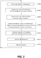
- Fig. 2 is a flow chart indicating transition of states or operations in an example optical response measuring method implemented into an optical response measuring device 100. The description will be made with reference also to Fig. 1 .
- the pair of light beams LP is generated (S102) at the light source 122.
- This pair of light beams LP is then irradiated to the first wavelength conversion element 126 for generating measurement light LM (S104).
- the measurement light LM is generated though non-linear wavelength conversion (for example, difference frequency generation) within the first wavelength conversion element 126.
- light that carries the phase of the pair of light beams LP is used for reference light LR.
- the reference light LR is indicated in Fig. 1 by fraction of light of the pair of light beams LP that is transmitted through the first wavelength conversion element 126.
- the measurement light LM is then irradiated to an object for measurement 50 for obtaining detection light LS, which represents optical response thereof (S106).
- detection light LS which represents optical response thereof (S106).
- intensity and phase difference of detection light LS are determined according to the optical response at each point under illumination in the illumination area S of the object for measurement 50 to the measurement light.
- the detection light LS is then irradiated to second wavelength conversion element 164 together with the reference light LR, which carries the phase of the pair of light beams LP (S108). Due to wavelength conversion function of a non-linear optical phenomenon in the second wavelength conversion element 164, the intensity of the reference light LR is modulated to have intensity representing the intensity or phase difference of the detection light LS at each point under illumination of the object for measurement 50.
- the modulation depth of the intensity of the reference light LR depends also on whether the wavenumbers of the detection light LS and the reference light LR satisfies an appropriate phase matching condition, such as collinear phase matching condition in the media of the second wavelength conversion element 164.
- the reference light having modulated intensity by the second wavelength conversion element 164 is called modulated reference light LD.
- the modulated reference light LD is then impinges on the sensor array 168 and its intensity is determined (S110). Throughout this detection plural local intensities in the modulated reference light LD are measured in parallel by separate sensors in the sensor array 168. Then signal indicating each intensity value is read out from the sensor array 168 (S112).
- a mirror 142 and a dielectric multi-layered mirror 144 are used as in Fig. 1 .
- the mirror 142 is arranged to relay the reference light LR from the first wavelength conversion element 126 to the second wavelength conversion element 164.
- the dielectric multi-layered mirror 144 is arranged to relay the detection light LS to the second wavelength conversion element 164 while light axes of the reference light LR and the detection light LS are aligned with each other.
- the detection light cut filter 166 may be arranged. The characteristics of the detection light cut filter 166 are adjusted while considering intensity of the detection light LS leaked after transmission there and the influence of the detection light on the sensor array 168, in such a manner that the characteristics matches the wavelength of the modulated reference light LD and that of the detection light LS. For instance, when the sensor array 168 is insensible to the detection light LS then there is no need to provide the detection light cut filter 166.
- the detection light LS is visible light or infrared light
- Even when the detection light LS is terahertz wave it is possible to adjust convergence of the detection light to the object for measurement 50 by use of a parabolic mirror, or by use of a refraction element (prism, lens, or the like) made of cycloolefin system material that shows good transmittance at such terahertz waves, which has been developed by a part of the inventors (Patent Document 4) .
- the reference light LR may be selected from different ones as long as it carries the phase of the pair of light beams LP. For example, it is possible to split a part of the pair of light beams LP before it impinges on the first wavelength conversion element 126 and then the part is irradiated to second wavelength conversion element 164 for the reference light LR by some arbitral optical element, not shown, without irradiating on any non-linear optical element.
- Such imaging can be carried out over a volume range where the detection light LS is obtained without losing coherence to the measurement light LM out of a volume range that is bounded by the illumination area S irradiated by the measurement light LM and maximum depth of the reach of the measurement light LM.
- the sensor array 168 is selected to one that is capable of obtaining optical intensities at different position in parallel, such as one-dimensional or two-dimensional sensor arrays, then it is possible to obtain intensity and phase values at different points under illumination in the illumination area S of the object for measurement 50 without resorting to scanning operation.
- the imaging volume range will be described in relation to the optical response measuring device 100 in Fig. 1 , which is an example adopting a flip configuration between the measurement light LM and the detection light LS.
- the range where the tomogram can be obtained from the object for measurement 50 in the object for measurement 50 is bounded by the illumination area S for lateral directions of beam, whereas its depth is determined by a range where the detection light LS is not attenuated and its coherence is not lost and where the detection light LS is not attenuated and its coherence is not lost.
- intensity of the measurement light LM at each point under illumination is mainly influenced by degree of direction reversing property, such as reflection or scattering.
- the phase difference of the measurement light LM at each point under illumination is mainly influenced by position of a feature under measurement F related to that phenomenon along the depth direction in the object for measurement 50.
- position of a feature under measurement F related to that phenomenon along the depth direction in the object for measurement 50.
- the second wavelength conversion element 164 receives input light of detection light LS and reference light LR ( Fig. 1 ).
- the reference light LR here is a part of the pair of light beams LP.
- Fig. 1 depicts utilized reference light LR as transmitted fraction of the pair of light beams that were not converted to the measurement light LM in the first wavelength conversion element 126.
- the detection light LS and reference light LR are aligned with each other to have an identical optical axis such that they enter into the second wavelength conversion element 164 from the same direction, and a breadth of the reference light LR cross section is adjusted to cover the entire breadth of the cross section of the detection light LS, though the breadths are not shown in the figures.
- the relationship between the second wavelength conversion element 164 and wavelengths for the reference light LR and the detection light LS is typically a collinear phase matching conditions.
- each intensity measured by the sensor array 168 is obtained independently, i.e., without affecting with each other, where each intensity is attributable to the detection light LS from each point under illumination included in the illumination area S of the object for measurement 50. This will be further described by way of Fig. 3 .
- Fig. 3 is a schematic diagram illustrating a structure of detection optics 160 in the optical response measuring device 100 depicted in Fig. 1 .
- the sensor array 168 has an array of optical intensity sensors in two-dimensional manner.
- depicted position of the object for measurement 50 is moved to a position that is geometrically equivalent to an original position along a reflected optical path by the dielectric multi-layered mirror 144 ( Fig. 1 ).
- the illumination area S of the object for measurement 50 has a two-dimensional range that matches to the breadth of the measurement light LM.
- Three-dimensional points within the reach of the transmitted measurement light LM at each point under illumination produce optical response according to interaction between the measurement light LM and media at the points .
- FIG. 3 indicates a situation in which the detection light LS from the measurement light LM at first, second, and third points under illumination RA, RB, and RC in an object for measurement 50 is detected, where these points under illumination are examples of each point under illumination in the illumination area S.
- the detection light is obtained from points along invasive direction at each of the first, second, and third points under illumination RA, RB, and RC.
- minute fractions FA and FB correspond to the feature under measurement F (not shown in Fig. 3 ) at the first and second points under illumination RA and RB
- the detection light from the first and second points under illumination RA and RB is influenced by optical responses at minute fractions FA and FB.
- relevant optical response at each point in an object for measurement 50 is any sort of optical responses to the measurement light LM
- electromagnetic wave of the detection light LS is emitted toward various directions while its wavelength is identical to that of the measurement light LM.
- the detection light LS from the first point under illumination RA for example, will travel toward various directions as illustrated in Fig. 3 . Consequently, position and incidence direction of the detection light LS illuminated to the second wavelength conversion element 164 are distributed.
- the detection light LS from the first point under illumination RA in Fig. 3 may be transmitted through the second wavelength conversion element 164 along various directions allowed by the geometrical configuration of the object for measurement 50 and the second wavelength conversion element 164.
- the intensity of the reference light LR is modulated due to influence by the detection light LS at each point in the second wavelength conversion element 164 according to the local intensity and phase of the detection light LS. It should be noted that an efficient modulation of the intensity requires an appropriate phase matching condition to be satisfied in the second wavelength conversion element 164. In a typical case when a collinear phase matching is required, although the detection light LS may travel along various directions, only the detection light that travel along a direction satisfying the collinear phase matching condition has influence on the reference light LR.
- the reference light LR incident on the second wavelength conversion element 164 is a collimated light beam, which is not shown in Fig.
- Fig. 3 also depicts a relationship among wavenumber vectors k 1 , k 2 , and k 3 to be satisfied in media of the second wavelength conversion element 164 by the light of first and the second wavelengths in the reference light LR and the detection light LS according to the collinear phase matching condition.
- resulting modulated reference light LD has modulated local intensities while it is influenced by phase information at each point under illumination.
- Fig. 3 indicates the modulated reference light beams LD_A and LD_B while distinguishing the modulated reference light LD for the first and second points under illumination from each other.
- the modulated reference light LD whose intensity is modulated reaches toward separate sensor pixels PA and PB that corresponds to the first and second points under illumination RA and RB respectively.
- the detection light LS toward a direction that does not satisfy the phase matching condition with the reference light LR goes through the second wavelength conversion element 164 without interacting with each other.
- Phase variation at the third point under illumination RC also influences the intensity measured at the sensor pixel PC in the same manner.
- the function of the second wavelength conversion element 164 is not only to convert wavelength but to conduct projection for mapping each point under illumination in the illumination area of the object for measurement 50 onto each sensor pixels of the sensor array 168.
- the modulation is carried out according to intensity and phase at first and second points under illumination RA and RB, and such measurement is carried out concurrently. Local intensities from different points under illumination in the modulated reference light LD are not mixed up on the sensor array 168.
- a secondary effect can be expected.
- the detection light LS that impinges on the second wavelength conversion element 164 may have a fraction that shows less coherence or no coherence at all while having the wavelength of the detection light LS. Since most significant factor that reduces the coherence is scattering in the object for measurement 50, it is likely that the phase information for detection light travelling along a different direction from one for the mapping stated above might have been lost.
- a direction for which the intensity modulation is performed that is a direction for which the mapping is performed, from a range of detection light LS, by utilizing directions of the second wavelength conversion element 164 and the reference light LR. This allows us to remove detection light LS that has already lost the phase information in the measurement result.
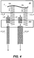
- Fig. 4 is a schematic diagram illustrating function of the second wavelength conversion element 164 that receives reference light LR and detection light LS.
- the detection light LS and the reference light LR that keep the optical responses in the first and the second points under illumination RA and RB are incident into the second wavelength conversion element 164 and the phase matching condition in the media there is satisfied, non-linear wave conversion takes place in the second wavelength conversion element 164.
- the degree of the non-linear wavelength conversion function at this stage is related to the optical electric field and the phase in the detection light LS.
- the measurement light entering into the object for measurement 50 experiences optical response by the feature under measurement F where the degree of the response depends on position along the depth direction at each point under illumination of the object for measurement 50, the detection light LS influenced by the intensity and phase is then incident into second wavelength conversion element 164.
- the second wavelength conversion element 164 also receives reference light LR at the same time.
- the reference light LR is depicted in isolated waves at each position in Fig. 4 , it is actually a beam, such as plane wave, and carries the phase of the pair of light beams LP, such as a part of the pair of light beams LP of the first and the second wavelengths.
- the detection light LS has different amplitude in the optical electric field and different phase in general depending on difference of points under illumination of the feature under measurement F.
- the amplitude of the optical electric field is typically influenced by differences in optical property of the feature under measurement F from the surrounding material.
- the differences in the optical property are those that determine a refraction index or a dielectric coefficient in a phenomenological context, such as difference of electron density.
- other factors that weaken electric field caused by the media in the way at the wavelength of the measurement light or detection light such as absorption and scattering, may have such effects.
- the phase is influenced by an amount of step of refractive index found by the difference from the surrounding media.
- Such step of the index is basically unchanged so long as the magnitude of index of the feature under measurement F is kept with relative to the surrounding.
- the difference explained in terms of optical phenomenon may also be explained in a microscopic context by whether phase retardation in microscopic optical response of the feature under measurement F to the measurement light has larger value than the surrounding or not.
- Another factor having influence on the phase difference is optical path difference among the points under illumination in the feature under measurement F, or difference in the optical path lengths.
- the configuration is reflective one as in Fig. 1 , the optical path length is measured in a round trip path of the measurement light, which travels to the feature under measurement F and returns back from there until it exits to the outside.
- Actual phase difference is influenced by sum of the phase retardation mentioned above and the phase difference due to the optical path difference.
- Fig. 4 illustrates a case where only the phase is different due to the optical path difference. That is, Fig. 4 is made on the assumption that the measurement light (not shown in Fig. 4 ) enters into the object for measurement 50 while maintaining its phase with relative to the pair of light beams (not shown in Fig. 4 ) and reaches the first and the second points under illumination RA and RB while maintaining the intensity, i.e., the amplitude of the optical electric field. Even in such a case, the optical path lengths for reaching the points under illumination RA and RB are different with each other as is indicated in Fig. 4 .
- the phase difference between the reaches to the points under illumination RA and RB is, for example, 90-degree delay for the point under illumination RB with relative to the point under illumination RA when entering, and another 90-degree delay when exiting.
- Fig. 4 depicts an optical path difference after exiting in the detection light that corresponds to a phase difference of 180 degrees.
- the light beams LS_A and LS_B which are detection light LS from the first and the second points under illumination RA and RB respectively, are influenced by the optical response and the phase difference corresponding to their position at the minute fractions FA and FB in the feature under measurement F. Consequently, there should found a difference in function of the non-linear wavelength conversion by the reference light LR between the light beam LS_A and the light beam LS_B, where their phase values should be determined at the first and second point under illumination RA and RB respectively.
- the function of the non-linear wavelength conversion in the second wavelength conversion element 164 is sensitive to phase of the detection light LS with relative to one for the reference light LR, thus it is possible to obtain the modulated reference light beams LD_A and LD_B having intensity values corresponding to their phase values from the light beams LS_A and LS_B of the first and the second points under illumination RA and RB.
- intensity values for each position of the modulated reference light LD measured by the sensor array 168 are influenced by the positions of the first and the second points FA and FB. It is to be noted that the intensity of the modulated reference light LD is also influenced when there is difference in the intensity values (difference in amplitudes of the optical electric fields) of the detection light beams LS_A and LS_B.
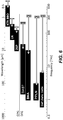
- Fig. 5 is a graph showing an example intensity of modulated reference light calculated for phase values of detection light in an idealized optical response measurement of the present embodiment.
- Conditions for the calculation are the beams of reference light LR carrying the phase of a pair of light beams of the first and the second wavelengths have the same intensity, or unit value of 1, and the detection light having matched phase with the reference light LR of an intensity of 0.01 is irradiated thereto. Any phenomena that may diminish intensity or dissipate the information, such as absorption inside the object for measurement 50 or de-coherence therein, are not included in this calculation.
- the phase difference on the horizontal axis is determined by selecting a value of phase fixed to those of the pair of light beams LP (reference light LR) and deriving the difference with it, in units of degree.
- the vertical axis represents an intensity value, or power, of the modulated reference light LD detected in the sensor array 168.
- Other assumptions such as equal sensitivity of the sensor array 168 for the first and the second wavelengths related to the reference light LR, and zero sensitivity on direct measurement of detection light LS are made.
- the zero sensitivity to the detection light can be easily realized by adopting a sensor array 168 having no sensing capability of the detection light or by providing a detection light cut filter 166 ( Fig. 1 ) when the sensor array 168 shows a sensitivity.
- Fig. 5 shows the difference in the phase in such a manner that they correspond to positions of the minute fractions FA and FB of a feature under measurement F, a typical one in Fig. 4 .
- the first wavelength conversion element 126 produces the measurement light LM from the pair of light beams LP of the first and the second wavelengths by difference frequency generation. During this process, the phase in generated the measurement light LM is determined by phase values of light of the first and the second wavelengths.
- the phase of the measurement light LM keeps a certain relationship with the phase of the first wavelength, and it keeps another certain relationship with the phase of the second wavelength.
- a certain relationship means that continuous and linear relationship is found in two optical waves, where one makes oscillation for a phase amount for a period of time and the other makes oscillation for another phase amount for the same period of time.
- temporal variation of relative phases between light of the first wavelength and light of the second wavelength may be kept constant or changed. This is because, although the pair of light beams LP formed by light of the first and the second wavelengths is used for generating the measurement light LM, exactly the same part of them or light carrying the same phase of them will become the reference light LR for the detection light LS. That is, to speak plainly, the measurement light LM keeps its coherent with phase of beats between light of the first wavelength and light of the second wavelength. Thus, assuming that the phase relationship between the light of the first wavelength and light of the second wavelength varies due to unknown reason, phases of the measurement light LM and the detection light LS are generated instantly in accordance with the variation. As a result, such temporal variation has no effect on the function in the second wavelength conversion element 164, thus the resulting intensity measurement of the modulated reference light LD is not affected at all.
- Light source in the embodiment of OPG is a laser having a single wavelength (first wavelength) and the light (referenced by LP) is input as a pump light to first wavelength conversion element 126.
- the first wavelength conversion element 126 is selected to be made of material that generates beams of light of two wavelengths by optical parametric generation from the pump light.
- the beams of light generated by the first wavelength conversion element 126 though the optical parametric generation has two wavelengths and are referred to as a signal light and an idler light.
- the signal light of these beams of light is used for the measurement light LM ( Fig. 1 ), and the idler light is used for the reference light LR together with a part of the pump light.
- the wavelengths of the measurement light LM and the idler light are determined by the OPG operation in the first wavelength conversion element 126 from a view point of the governing laws, and selected to be a wavelength suitable for measurement by the measurement light LM, or a measurement wavelength, from a view point of the application.
- the second wavelength conversion element 164 generates modulated reference light LD based on a reverse function of one in the first wavelength conversion element 126.
- the second wavelength conversion element 164 is irradiated by detection light LS obtained from an illumination area on the object for measurement irradiated by the measurement light LM and a reference light LR.
- Non-linear optical phenomenon occurred in the second wavelength conversion element 164 is sum frequency generation of a part of the reference light LR and the detection light LS, which were the idler light and the signal light in the first wavelength conversion element 126.
- the reference light LR carries a phase of the pump light and the idler light in the first wavelength conversion element 126.
- the detection light LS has the same wavelength as the measurement light LM and is influenced by the phase information in the object for measurement 50.
- the second wavelength conversion element 164 is operated on light beams LS_A and LS_B, which are detection light LS from the first and second points under illumination RA and RB respectively and modulates local intensities of reference light LR independently, as was described in the above with reference to Figs. 3 and 4 . Consequently, partial intensities of the modulated reference light LD are modulated such that they are influenced by the phase information at each point under illumination.
- Collinear phase matching condition in the second wavelength conversion element 164 and resulting projection operation are the same as those in Fig. 3 .
- Intensity of the light of an identical wavelength to the pump light (light of first wavelength) in the modulated reference light LD is measured by the sensor array 168. Since light beams LS_A and LS_B of the detection light LS are superimposed, or interfered, to pump light (light of first wavelength) and signal light (light of second wavelength) in the reference light LR during the non-linear wavelength conversion (sum frequency generation) in the second wavelength conversion element 164, the intensity of the modulated reference light LD is influenced by the phase information of the object for measurement 50.
- the mechanism described here is the same as those described in connection with DFG with reference to Fig. 4 . Also, the operation of intensity measurement of the modulated reference light LD by the sensor array 168 is the same as explained.
- the detection light cut filter 166 is configured such that it can pass light over the wavelength range of pump light in the reference light LR, for example.
- the calculated example for the intensity of the modulated reference light LD against phase of the detection light LS in Fig. 5 is also the same.
- the optical response measuring method can be practiced similarly in the operation step S102 of the light source 122, except that the pump light LP is generated instead of the pair of light beams.
- DFG and OPG mentioned above are typical examples of phenomena that can be applied to the present embodiment, thus any of non-linear optical phenomena similar to those can be applied to embodiment of the present invention.
- An example applicable to the embodiment of the present invention is a phenomenon called injection seeded OPG, a type of OPG. Since light of two wavelengths is input to the first wavelength conversion element 126 in this injection seeded OPG, its operation is similar to a case of DFG (difference frequency generation).
- OPA optical parametric amplification
- the term OPA is one that denotes the same operation as the DFG mentioned above while paying attention on light of third wavelength.
- the term OPA is used in cases when the phenomenon is recognized as one that amplifies second wavelength light, which is a longer wavelength than first wavelength.
- the phenomenon called the optical parametric amplification (OPA) can be explained in the same way as those for the DFG stated above.
- OPG Optical Parametric Generation
- Fig. 6 is an explanation chart indicating representative combinations of wavelengths for pair of light beams and non-linear optical crystals and wavelength ranges, or frequency ranges, of measurement light generated from each combination. The relationship indicated in Fig. 6 would be summarized as in Table 1 with numerical values for the first and the second wavelengths for the pair of light beams for each material.
- Table 1 1 st Wavelength Conversion Element 1 st , 2 nd Wavelength Frequency or Wavelength of Measurement Light
- the same combinations for the wavelength and material as those for the first wavelength conversion element 126 may be adopted for the second wavelength conversion element 164.
- the value for ⁇ (2) (tensor element) will be 10 times or more for inorganic crystals. This means that the non-linear optical phenomenon can be easily seen for measuring wavelength of THz range, therefore, there is no difficulty in practicing the embodiment in such a range.
- the measurement light LM irradiated to the object for measurement 50 may be infrared light or terahertz light as indicated in Table 1.
- the wavelength is chosen from available wavelength range based on type of the object for measurement 50, type of tissue in the object for measurement 50 (feature under measurement F) is to be detected, and property of the optical response. Generally speaking, longer wavelength will be chosen in order to obtain structural information of deep invasion from the surface because a longer wavelength will have more significant transmission capability.
- first wavelength conversion element 126 and second wavelength conversion element 164 can be of the same material, or of different material. Typically, it is favorable that the same material is adopted for the first wavelength conversion element 126 and the second wavelength conversion element 164.
- DFG is adopted, for example, if the pair of light beams of the first and the second wavelengths is adopted and made incident on a first wavelength conversion element 126 of DAST crystal, and the measurement light maintaining the phase with relative to the pair of light beams, the it is preferable that DAST is also selected for the second wavelength conversion element 164 on which reference light and detection light are irradiated.
- the first wavelength conversion element 126 and the second wavelength conversion element 164 can meet a phase matching condition at the same wavelength when the measurement wavelength light is modulated for the measurement.
- OPG it is also preferable that the same material is adopted for the first wavelength conversion element 126 and the second wavelength conversion element 164 based on the same reason.
- measurement is carried out on the shape and position of a feature under measurement F in the object for measurement 50.
- the phase values of the detection light LS obtained at the first and second points under illumination RA and RB in the illumination area S of the object for measurement 50, or the first phase and the second phase, are influenced especially by internal local structure along the invasive direction inside the object for measurement 50, such as the feature under measurement F of the object for measurement 50 at each position. Therefore, if the sensor array 168 is used for the measurement, the first and second intensities in the modulated reference light LD that are influenced by the first and the second phase values enable to make a measurement of minute fractions FA and FB in a feature under measurement F inside of the object for measurement 50 without using scanning technique.
- Advantages of the embodiment of the present invention may be found in the fact that detection wavelength of detectors and wavelength for measurement or detection are separated from each other. Even if the measurement is attempted with measurement or detection light of a wavelength for which manufacturing of the detectors is difficult, it is possible to fit a detector, such as a sensor array 168, to a wavelength of the modulated reference light LD. This is advantageous in that it allows us to pursue both of a wavelength in view of obtaining optical response from the object for measurement 50 and a detector such as a sensor array 168 for concurrent detecting plural points under illumination.
- the structure of the optical response measuring device 100 indicated in Fig. 1 is merely an exemplary one.
- the measurement light is selected to have a wavelength that can travel through the object for measurement 50, it may be advantageous to obtain optical response by light passing through, or to receive detection light that goes off from an optical axis due to scattering for obtaining optical response of the object for measurement 50 to the measurement light.
- the reference light is a part of the pair of light beams that will generate the measurement light LM, then it is not necessary that the reference light is one that passed through the first wavelength conversion element 126 as in Fig. 1 .
- frequency sweeping technique in application for obtaining tomogram by use of the measurement scheme of optical response in the embodiment of the present invention will be described. It is advantageous to modulate a wavelength of detection light or frequency by sweeping when capturing a tomogram inside of the object for measurement 50 in the embodiment of the present invention. It is possible to capture tomogram information if the frequency sweeping is carried out in the detection light LS for obtaining tomogram information in a similar manner to SS-OCT, which has been adopted in existing OCTs.
- the measurement principle mentioned above is applicable as in the same way when the frequency sweep is adopted for the detection light. This is because it is possible to perform non-linear conversion in the first wavelength conversion element 126 and the second wavelength conversion element 164 at each frequency (each wavelength) of the detection light, there is no need for paying attention on the difference of frequency (wavelength) for the time difference for which measurement light (detection light) travels from the first wavelength conversion element 126 to the second wavelength conversion element 164, and the measurement principle is true at every moment.
- the wavelength of at least any of the pair of light beams of the first wavelength and the second wavelength is swept for sweeping the frequency of the detection light.
- Fig. 1 depicts a modulation controller 128 for frequency sweeping.
- the light source 122 modulates any of the first wavelength and the second wavelength in response to control by the modulation controller 128, thereby at least one of the two wavelengths of the reference light is swept.
- the wavelength of the detection light entering into the sensor array 168 is also swept.
- Typical timing of the frequency sweeping in this embodiment of the present invention is after the signal readout ( Fig. 2 , S112) subsequent to the intensity detection corresponding to plural points under illumination, or during the readout concurrently. This is expressed in Fig. 2 by step S114 of updating frequency after step S122 of signal readout. Thus, there is no need to extremely boost the frequency sweep rate. Also, there is no particular trouble in the readout of the sensor array 168.
- existing SS-OCT requires at least one frequency sweep action to obtain invasive direction information at a focal point, (so called A-scan) for the information along the invasive direction.
- A-scan invasive direction information at a focal point
- processing speed of existing SS-OCT is regulated by process time for a single A-scan, that is, capturing rate of tomograms is determined by the frequency sweep rate for the light source.
- the present invention is applicable to any device for measuring optical response of an object for measurement.
Landscapes
- Physics & Mathematics (AREA)
- Nonlinear Science (AREA)
- General Physics & Mathematics (AREA)
- Health & Medical Sciences (AREA)
- Biochemistry (AREA)
- Life Sciences & Earth Sciences (AREA)
- Chemical & Material Sciences (AREA)
- Analytical Chemistry (AREA)
- General Health & Medical Sciences (AREA)
- Immunology (AREA)
- Pathology (AREA)
- Spectroscopy & Molecular Physics (AREA)
- Optics & Photonics (AREA)
- Toxicology (AREA)
- Investigating Or Analysing Materials By Optical Means (AREA)
- Optical Modulation, Optical Deflection, Nonlinear Optics, Optical Demodulation, Optical Logic Elements (AREA)
Applications Claiming Priority (2)
| Application Number | Priority Date | Filing Date | Title |
|---|---|---|---|
| JP2014207559 | 2014-10-08 | ||
| PCT/JP2015/078254 WO2016056522A1 (fr) | 2014-10-08 | 2015-10-05 | Dispositif de mesure de réponse optique et procédé de mesure de réponse optique |
Publications (3)
| Publication Number | Publication Date |
|---|---|
| EP3206014A1 true EP3206014A1 (fr) | 2017-08-16 |
| EP3206014A4 EP3206014A4 (fr) | 2018-03-28 |
| EP3206014B1 EP3206014B1 (fr) | 2020-02-26 |
Family
ID=55653133
Family Applications (1)
| Application Number | Title | Priority Date | Filing Date |
|---|---|---|---|
| EP15848227.3A Active EP3206014B1 (fr) | 2014-10-08 | 2015-10-05 | Dispositif de mesure de réponse optique et procédé de mesure de réponse optique |
Country Status (4)
| Country | Link |
|---|---|
| US (1) | US10345224B2 (fr) |
| EP (1) | EP3206014B1 (fr) |
| JP (1) | JP6685553B2 (fr) |
| WO (1) | WO2016056522A1 (fr) |
Families Citing this family (7)
| Publication number | Priority date | Publication date | Assignee | Title |
|---|---|---|---|---|
| WO2018171869A1 (fr) * | 2017-03-21 | 2018-09-27 | MAX-PLANCK-Gesellschaft zur Förderung der Wissenschaften e.V. | Procédés et dispositifs de mesure de changements de la réponse de polarisation d'un échantillon par spectroscopie infrarouge à domaine temporel (spectroscopie vibrationnelle à résolution de champ) |
| JP2019144435A (ja) * | 2018-02-21 | 2019-08-29 | 沖電気工業株式会社 | テラヘルツ波検出素子 |
| JP6980108B2 (ja) * | 2018-06-06 | 2021-12-15 | 株式会社日立ハイテク | 分光測定装置、及び分光測定方法 |
| CN109618479B (zh) * | 2019-01-18 | 2023-09-29 | 欧普照明股份有限公司 | 光源参数测量方法、装置、照明系统和终端设备 |
| US20220151510A1 (en) * | 2019-02-22 | 2022-05-19 | Toi Labs, Inc. | User detection and identification in a bathroom setting |
| CN113933268B (zh) * | 2020-07-13 | 2024-03-19 | 中移物联网有限公司 | 一种光学检测装置及光学检测方法 |
| CN113189824B (zh) * | 2021-04-21 | 2022-08-09 | 中国科学院上海光学精密机械研究所 | 一种基于双非线性光学过程的宽带光参量放大装置 |
Family Cites Families (13)
| Publication number | Priority date | Publication date | Assignee | Title |
|---|---|---|---|---|
| JPH0635946B2 (ja) | 1990-11-06 | 1994-05-11 | 直弘 丹野 | 光波反射像測定装置 |
| US5956355A (en) | 1991-04-29 | 1999-09-21 | Massachusetts Institute Of Technology | Method and apparatus for performing optical measurements using a rapidly frequency-tuned laser |
| WO1992019930A1 (fr) | 1991-04-29 | 1992-11-12 | Massachusetts Institute Of Technology | Procede et appareil d'imagerie optique et de mesure |
| US5451785A (en) * | 1994-03-18 | 1995-09-19 | Sri International | Upconverting and time-gated two-dimensional infrared transillumination imaging |
| JP4183546B2 (ja) | 2003-04-11 | 2008-11-19 | 独立行政法人理化学研究所 | テラヘルツ波光学系 |
| JP2005172779A (ja) * | 2003-12-10 | 2005-06-30 | Semiconductor Res Found | 電磁波を照射してバクテリア、ウィルスおよび毒性物質を測定する方法および装置 |
| JPWO2006085403A1 (ja) * | 2005-02-10 | 2009-01-29 | 国立大学法人大阪大学 | 実時間テラヘルツ・トモグラフィー装置および分光イメージング装置 |
| JP5063325B2 (ja) * | 2007-12-14 | 2012-10-31 | 独立行政法人理化学研究所 | キャリア濃度測定装置およびキャリア濃度測定方法 |
| JP5489620B2 (ja) * | 2008-12-02 | 2014-05-14 | オリンパス株式会社 | 観察装置 |
| JP5601562B2 (ja) * | 2009-09-04 | 2014-10-08 | 独立行政法人理化学研究所 | 移動度測定装置及びその方法、並びに、抵抗率測定装置及びその方法 |
| JP5943594B2 (ja) | 2011-01-14 | 2016-07-05 | キヤノン株式会社 | テラヘルツ波素子、テラヘルツ波検出装置、テラヘルツ時間領域分光システム及びトモグラフィ装置 |
| JP6139327B2 (ja) * | 2012-08-30 | 2017-05-31 | アークレイ株式会社 | テラヘルツ波分光測定装置及び方法、非線形光学結晶の検査装置及び方法 |
| JP6220128B2 (ja) * | 2013-01-08 | 2017-10-25 | アークレイ株式会社 | テラヘルツ波発生装置及びテラヘルツ波測定方法 |
-
2015
- 2015-10-05 JP JP2016553101A patent/JP6685553B2/ja active Active
- 2015-10-05 EP EP15848227.3A patent/EP3206014B1/fr active Active
- 2015-10-05 WO PCT/JP2015/078254 patent/WO2016056522A1/fr active Application Filing
- 2015-10-05 US US15/517,925 patent/US10345224B2/en active Active
Also Published As
| Publication number | Publication date |
|---|---|
| US10345224B2 (en) | 2019-07-09 |
| WO2016056522A1 (fr) | 2016-04-14 |
| JP6685553B2 (ja) | 2020-04-22 |
| US20170307515A1 (en) | 2017-10-26 |
| EP3206014A4 (fr) | 2018-03-28 |
| EP3206014B1 (fr) | 2020-02-26 |
| JPWO2016056522A1 (ja) | 2017-08-31 |
Similar Documents
| Publication | Publication Date | Title |
|---|---|---|
| US10345224B2 (en) | Optical response measuring device and optical response measuring method | |
| US8204300B2 (en) | Image forming method and optical coherence tomograph apparatus using optical coherence tomography | |
| JP5037929B2 (ja) | テラヘルツ波を用いた対象物の情報取得装置及び方法 | |
| JP4963640B2 (ja) | 物体情報取得装置及び方法 | |
| JP5134177B2 (ja) | 電場に基づいた光散乱分光法を用いたシステム | |
| US8440971B2 (en) | Examining apparatus | |
| JP6008299B2 (ja) | 光干渉計、情報取得装置、及び情報取得方法 | |
| US8879070B2 (en) | Two beams formed by Wollaston prism in sample arm in an optical coherence tomography apparatus | |
| US5565986A (en) | Stationary optical spectroscopic imaging in turbid objects by special light focusing and signal detection of light with various optical wavelengths | |
| JP5736325B2 (ja) | 光学装置 | |
| KR20140096262A (ko) | 스마트폰에 장착된 광 간섭 단층 촬영 시스템 | |
| US9164031B2 (en) | Measurement apparatus and method, tomography apparatus and method | |
| WO2016084322A1 (fr) | Appareil et procédé de mesure pour mesurer des impulsions térahertz | |
| US20150192467A1 (en) | Spectral-domain interferometric method and system for characterizing terahertz radiation | |
| JPWO2006085403A1 (ja) | 実時間テラヘルツ・トモグラフィー装置および分光イメージング装置 | |
| WO2015001918A1 (fr) | Procédé et dispositif de mesure de brouillage | |
| JP2019526060A (ja) | 音響共鳴分光測定方法及びシステム | |
| JP5645125B2 (ja) | 発汗測定方法 | |
| WO2016059939A1 (fr) | Procédé d'imagerie tomographique optique, dispositif associé, et programme associé | |
| JP6422449B2 (ja) | 計測装置及び計測方法 | |
| JP2010175271A (ja) | 光断層画像表示システム | |
| Suzuki et al. | 3D thickness measurement using pulse-driven optical coherence tomography based on wavelet transform | |
| Yasui et al. | Tutorial: Real-time coherent terahertz imaging of objects moving in one direction with constant speed | |
| Zhang et al. | Real-Time, Two-Dimensional Terahertz Beam Imaging | |
| JP2016134437A (ja) | ファイバーリングレーザー、光パルス、及び光断層画像化装置 |
Legal Events
| Date | Code | Title | Description |
|---|---|---|---|
| STAA | Information on the status of an ep patent application or granted ep patent |
Free format text: STATUS: THE INTERNATIONAL PUBLICATION HAS BEEN MADE |
|
| PUAI | Public reference made under article 153(3) epc to a published international application that has entered the european phase |
Free format text: ORIGINAL CODE: 0009012 |
|
| STAA | Information on the status of an ep patent application or granted ep patent |
Free format text: STATUS: REQUEST FOR EXAMINATION WAS MADE |
|
| 17P | Request for examination filed |
Effective date: 20170428 |
|
| AK | Designated contracting states |
Kind code of ref document: A1 Designated state(s): AL AT BE BG CH CY CZ DE DK EE ES FI FR GB GR HR HU IE IS IT LI LT LU LV MC MK MT NL NO PL PT RO RS SE SI SK SM TR |
|
| AX | Request for extension of the european patent |
Extension state: BA ME |
|
| DAV | Request for validation of the european patent (deleted) | ||
| DAX | Request for extension of the european patent (deleted) | ||
| A4 | Supplementary search report drawn up and despatched |
Effective date: 20180228 |
|
| RIC1 | Information provided on ipc code assigned before grant |
Ipc: G02F 1/37 20060101ALI20180222BHEP Ipc: G01N 21/3581 20140101ALI20180222BHEP Ipc: G01N 21/17 20060101AFI20180222BHEP |
|
| STAA | Information on the status of an ep patent application or granted ep patent |
Free format text: STATUS: EXAMINATION IS IN PROGRESS |
|
| 17Q | First examination report despatched |
Effective date: 20190204 |
|
| REG | Reference to a national code |
Ref country code: DE Ref legal event code: R079 Ref document number: 602015047887 Country of ref document: DE Free format text: PREVIOUS MAIN CLASS: G01N0021170000 Ipc: G01B0009020000 |
|
| GRAP | Despatch of communication of intention to grant a patent |
Free format text: ORIGINAL CODE: EPIDOSNIGR1 |
|
| STAA | Information on the status of an ep patent application or granted ep patent |
Free format text: STATUS: GRANT OF PATENT IS INTENDED |
|
| RIC1 | Information provided on ipc code assigned before grant |
Ipc: G01B 9/02 20060101AFI20190830BHEP Ipc: G02F 1/35 20060101ALI20190830BHEP |
|
| INTG | Intention to grant announced |
Effective date: 20190916 |
|
| GRAS | Grant fee paid |
Free format text: ORIGINAL CODE: EPIDOSNIGR3 |
|
| GRAA | (expected) grant |
Free format text: ORIGINAL CODE: 0009210 |
|
| STAA | Information on the status of an ep patent application or granted ep patent |
Free format text: STATUS: THE PATENT HAS BEEN GRANTED |
|
| RAP1 | Party data changed (applicant data changed or rights of an application transferred) |
Owner name: RIKEN |
|
| AK | Designated contracting states |
Kind code of ref document: B1 Designated state(s): AL AT BE BG CH CY CZ DE DK EE ES FI FR GB GR HR HU IE IS IT LI LT LU LV MC MK MT NL NO PL PT RO RS SE SI SK SM TR |
|
| REG | Reference to a national code |
Ref country code: GB Ref legal event code: FG4D |
|
| REG | Reference to a national code |
Ref country code: CH Ref legal event code: EP |
|
| REG | Reference to a national code |
Ref country code: AT Ref legal event code: REF Ref document number: 1238166 Country of ref document: AT Kind code of ref document: T Effective date: 20200315 |
|
| REG | Reference to a national code |
Ref country code: IE Ref legal event code: FG4D |
|
| REG | Reference to a national code |
Ref country code: DE Ref legal event code: R096 Ref document number: 602015047887 Country of ref document: DE |
|
| PG25 | Lapsed in a contracting state [announced via postgrant information from national office to epo] |
Ref country code: FI Free format text: LAPSE BECAUSE OF FAILURE TO SUBMIT A TRANSLATION OF THE DESCRIPTION OR TO PAY THE FEE WITHIN THE PRESCRIBED TIME-LIMIT Effective date: 20200226 Ref country code: NO Free format text: LAPSE BECAUSE OF FAILURE TO SUBMIT A TRANSLATION OF THE DESCRIPTION OR TO PAY THE FEE WITHIN THE PRESCRIBED TIME-LIMIT Effective date: 20200526 Ref country code: RS Free format text: LAPSE BECAUSE OF FAILURE TO SUBMIT A TRANSLATION OF THE DESCRIPTION OR TO PAY THE FEE WITHIN THE PRESCRIBED TIME-LIMIT Effective date: 20200226 |
|
| REG | Reference to a national code |
Ref country code: NL Ref legal event code: MP Effective date: 20200226 |
|
| REG | Reference to a national code |
Ref country code: LT Ref legal event code: MG4D |
|
| PG25 | Lapsed in a contracting state [announced via postgrant information from national office to epo] |
Ref country code: GR Free format text: LAPSE BECAUSE OF FAILURE TO SUBMIT A TRANSLATION OF THE DESCRIPTION OR TO PAY THE FEE WITHIN THE PRESCRIBED TIME-LIMIT Effective date: 20200527 Ref country code: HR Free format text: LAPSE BECAUSE OF FAILURE TO SUBMIT A TRANSLATION OF THE DESCRIPTION OR TO PAY THE FEE WITHIN THE PRESCRIBED TIME-LIMIT Effective date: 20200226 Ref country code: IS Free format text: LAPSE BECAUSE OF FAILURE TO SUBMIT A TRANSLATION OF THE DESCRIPTION OR TO PAY THE FEE WITHIN THE PRESCRIBED TIME-LIMIT Effective date: 20200626 Ref country code: SE Free format text: LAPSE BECAUSE OF FAILURE TO SUBMIT A TRANSLATION OF THE DESCRIPTION OR TO PAY THE FEE WITHIN THE PRESCRIBED TIME-LIMIT Effective date: 20200226 Ref country code: LV Free format text: LAPSE BECAUSE OF FAILURE TO SUBMIT A TRANSLATION OF THE DESCRIPTION OR TO PAY THE FEE WITHIN THE PRESCRIBED TIME-LIMIT Effective date: 20200226 Ref country code: BG Free format text: LAPSE BECAUSE OF FAILURE TO SUBMIT A TRANSLATION OF THE DESCRIPTION OR TO PAY THE FEE WITHIN THE PRESCRIBED TIME-LIMIT Effective date: 20200526 |
|
| PG25 | Lapsed in a contracting state [announced via postgrant information from national office to epo] |
Ref country code: NL Free format text: LAPSE BECAUSE OF FAILURE TO SUBMIT A TRANSLATION OF THE DESCRIPTION OR TO PAY THE FEE WITHIN THE PRESCRIBED TIME-LIMIT Effective date: 20200226 |
|
| PG25 | Lapsed in a contracting state [announced via postgrant information from national office to epo] |
Ref country code: CZ Free format text: LAPSE BECAUSE OF FAILURE TO SUBMIT A TRANSLATION OF THE DESCRIPTION OR TO PAY THE FEE WITHIN THE PRESCRIBED TIME-LIMIT Effective date: 20200226 Ref country code: ES Free format text: LAPSE BECAUSE OF FAILURE TO SUBMIT A TRANSLATION OF THE DESCRIPTION OR TO PAY THE FEE WITHIN THE PRESCRIBED TIME-LIMIT Effective date: 20200226 Ref country code: RO Free format text: LAPSE BECAUSE OF FAILURE TO SUBMIT A TRANSLATION OF THE DESCRIPTION OR TO PAY THE FEE WITHIN THE PRESCRIBED TIME-LIMIT Effective date: 20200226 Ref country code: SM Free format text: LAPSE BECAUSE OF FAILURE TO SUBMIT A TRANSLATION OF THE DESCRIPTION OR TO PAY THE FEE WITHIN THE PRESCRIBED TIME-LIMIT Effective date: 20200226 Ref country code: EE Free format text: LAPSE BECAUSE OF FAILURE TO SUBMIT A TRANSLATION OF THE DESCRIPTION OR TO PAY THE FEE WITHIN THE PRESCRIBED TIME-LIMIT Effective date: 20200226 Ref country code: DK Free format text: LAPSE BECAUSE OF FAILURE TO SUBMIT A TRANSLATION OF THE DESCRIPTION OR TO PAY THE FEE WITHIN THE PRESCRIBED TIME-LIMIT Effective date: 20200226 Ref country code: LT Free format text: LAPSE BECAUSE OF FAILURE TO SUBMIT A TRANSLATION OF THE DESCRIPTION OR TO PAY THE FEE WITHIN THE PRESCRIBED TIME-LIMIT Effective date: 20200226 Ref country code: PT Free format text: LAPSE BECAUSE OF FAILURE TO SUBMIT A TRANSLATION OF THE DESCRIPTION OR TO PAY THE FEE WITHIN THE PRESCRIBED TIME-LIMIT Effective date: 20200719 Ref country code: SK Free format text: LAPSE BECAUSE OF FAILURE TO SUBMIT A TRANSLATION OF THE DESCRIPTION OR TO PAY THE FEE WITHIN THE PRESCRIBED TIME-LIMIT Effective date: 20200226 |
|
| REG | Reference to a national code |
Ref country code: AT Ref legal event code: MK05 Ref document number: 1238166 Country of ref document: AT Kind code of ref document: T Effective date: 20200226 |
|
| REG | Reference to a national code |
Ref country code: DE Ref legal event code: R097 Ref document number: 602015047887 Country of ref document: DE |
|
| PLBE | No opposition filed within time limit |
Free format text: ORIGINAL CODE: 0009261 |
|
| STAA | Information on the status of an ep patent application or granted ep patent |
Free format text: STATUS: NO OPPOSITION FILED WITHIN TIME LIMIT |
|
| PG25 | Lapsed in a contracting state [announced via postgrant information from national office to epo] |
Ref country code: IT Free format text: LAPSE BECAUSE OF FAILURE TO SUBMIT A TRANSLATION OF THE DESCRIPTION OR TO PAY THE FEE WITHIN THE PRESCRIBED TIME-LIMIT Effective date: 20200226 Ref country code: AT Free format text: LAPSE BECAUSE OF FAILURE TO SUBMIT A TRANSLATION OF THE DESCRIPTION OR TO PAY THE FEE WITHIN THE PRESCRIBED TIME-LIMIT Effective date: 20200226 |
|
| 26N | No opposition filed |
Effective date: 20201127 |
|
| PG25 | Lapsed in a contracting state [announced via postgrant information from national office to epo] |
Ref country code: PL Free format text: LAPSE BECAUSE OF FAILURE TO SUBMIT A TRANSLATION OF THE DESCRIPTION OR TO PAY THE FEE WITHIN THE PRESCRIBED TIME-LIMIT Effective date: 20200226 Ref country code: SI Free format text: LAPSE BECAUSE OF FAILURE TO SUBMIT A TRANSLATION OF THE DESCRIPTION OR TO PAY THE FEE WITHIN THE PRESCRIBED TIME-LIMIT Effective date: 20200226 |
|
| REG | Reference to a national code |
Ref country code: CH Ref legal event code: PL |
|
| GBPC | Gb: european patent ceased through non-payment of renewal fee |
Effective date: 20201005 |
|
| PG25 | Lapsed in a contracting state [announced via postgrant information from national office to epo] |
Ref country code: MC Free format text: LAPSE BECAUSE OF FAILURE TO SUBMIT A TRANSLATION OF THE DESCRIPTION OR TO PAY THE FEE WITHIN THE PRESCRIBED TIME-LIMIT Effective date: 20200226 Ref country code: LU Free format text: LAPSE BECAUSE OF NON-PAYMENT OF DUE FEES Effective date: 20201005 |
|
| REG | Reference to a national code |
Ref country code: BE Ref legal event code: MM Effective date: 20201031 |
|
| PG25 | Lapsed in a contracting state [announced via postgrant information from national office to epo] |
Ref country code: FR Free format text: LAPSE BECAUSE OF NON-PAYMENT OF DUE FEES Effective date: 20201031 |
|
| PG25 | Lapsed in a contracting state [announced via postgrant information from national office to epo] |
Ref country code: GB Free format text: LAPSE BECAUSE OF NON-PAYMENT OF DUE FEES Effective date: 20201005 Ref country code: LI Free format text: LAPSE BECAUSE OF NON-PAYMENT OF DUE FEES Effective date: 20201031 Ref country code: CH Free format text: LAPSE BECAUSE OF NON-PAYMENT OF DUE FEES Effective date: 20201031 Ref country code: BE Free format text: LAPSE BECAUSE OF NON-PAYMENT OF DUE FEES Effective date: 20201031 |
|
| PG25 | Lapsed in a contracting state [announced via postgrant information from national office to epo] |
Ref country code: IE Free format text: LAPSE BECAUSE OF NON-PAYMENT OF DUE FEES Effective date: 20201005 |
|
| PG25 | Lapsed in a contracting state [announced via postgrant information from national office to epo] |
Ref country code: TR Free format text: LAPSE BECAUSE OF FAILURE TO SUBMIT A TRANSLATION OF THE DESCRIPTION OR TO PAY THE FEE WITHIN THE PRESCRIBED TIME-LIMIT Effective date: 20200226 Ref country code: MT Free format text: LAPSE BECAUSE OF FAILURE TO SUBMIT A TRANSLATION OF THE DESCRIPTION OR TO PAY THE FEE WITHIN THE PRESCRIBED TIME-LIMIT Effective date: 20200226 Ref country code: CY Free format text: LAPSE BECAUSE OF FAILURE TO SUBMIT A TRANSLATION OF THE DESCRIPTION OR TO PAY THE FEE WITHIN THE PRESCRIBED TIME-LIMIT Effective date: 20200226 |
|
| PG25 | Lapsed in a contracting state [announced via postgrant information from national office to epo] |
Ref country code: MK Free format text: LAPSE BECAUSE OF FAILURE TO SUBMIT A TRANSLATION OF THE DESCRIPTION OR TO PAY THE FEE WITHIN THE PRESCRIBED TIME-LIMIT Effective date: 20200226 Ref country code: AL Free format text: LAPSE BECAUSE OF FAILURE TO SUBMIT A TRANSLATION OF THE DESCRIPTION OR TO PAY THE FEE WITHIN THE PRESCRIBED TIME-LIMIT Effective date: 20200226 |
|
| PGFP | Annual fee paid to national office [announced via postgrant information from national office to epo] |
Ref country code: DE Payment date: 20231020 Year of fee payment: 9 |