EP3205931B1 - Schnappverbindungsanordnung - Google Patents
Schnappverbindungsanordnung Download PDFInfo
- Publication number
- EP3205931B1 EP3205931B1 EP15753303.5A EP15753303A EP3205931B1 EP 3205931 B1 EP3205931 B1 EP 3205931B1 EP 15753303 A EP15753303 A EP 15753303A EP 3205931 B1 EP3205931 B1 EP 3205931B1
- Authority
- EP
- European Patent Office
- Prior art keywords
- fastener
- fixing member
- position limit
- disposed
- fastening
- Prior art date
- Legal status (The legal status is an assumption and is not a legal conclusion. Google has not performed a legal analysis and makes no representation as to the accuracy of the status listed.)
- Active
Links
Images



Classifications
-
- F—MECHANICAL ENGINEERING; LIGHTING; HEATING; WEAPONS; BLASTING
- F21—LIGHTING
- F21V—FUNCTIONAL FEATURES OR DETAILS OF LIGHTING DEVICES OR SYSTEMS THEREOF; STRUCTURAL COMBINATIONS OF LIGHTING DEVICES WITH OTHER ARTICLES, NOT OTHERWISE PROVIDED FOR
- F21V17/00—Fastening of component parts of lighting devices, e.g. shades, globes, refractors, reflectors, filters, screens, grids or protective cages
- F21V17/10—Fastening of component parts of lighting devices, e.g. shades, globes, refractors, reflectors, filters, screens, grids or protective cages characterised by specific fastening means or way of fastening
- F21V17/16—Fastening of component parts of lighting devices, e.g. shades, globes, refractors, reflectors, filters, screens, grids or protective cages characterised by specific fastening means or way of fastening by deformation of parts; Snap action mounting
-
- A—HUMAN NECESSITIES
- A44—HABERDASHERY; JEWELLERY
- A44B—BUTTONS, PINS, BUCKLES, SLIDE FASTENERS, OR THE LIKE
- A44B11/00—Buckles; Similar fasteners for interconnecting straps or the like, e.g. for safety belts
- A44B11/25—Buckles; Similar fasteners for interconnecting straps or the like, e.g. for safety belts with two or more separable parts
-
- A—HUMAN NECESSITIES
- A44—HABERDASHERY; JEWELLERY
- A44B—BUTTONS, PINS, BUCKLES, SLIDE FASTENERS, OR THE LIKE
- A44B13/00—Hook or eye fasteners
-
- F—MECHANICAL ENGINEERING; LIGHTING; HEATING; WEAPONS; BLASTING
- F16—ENGINEERING ELEMENTS AND UNITS; GENERAL MEASURES FOR PRODUCING AND MAINTAINING EFFECTIVE FUNCTIONING OF MACHINES OR INSTALLATIONS; THERMAL INSULATION IN GENERAL
- F16B—DEVICES FOR FASTENING OR SECURING CONSTRUCTIONAL ELEMENTS OR MACHINE PARTS TOGETHER, e.g. NAILS, BOLTS, CIRCLIPS, CLAMPS, CLIPS OR WEDGES; JOINTS OR JOINTING
- F16B2/00—Friction-grip releasable fastenings
- F16B2/20—Clips, i.e. with gripping action effected solely by the inherent resistance to deformation of the material of the fastening
- F16B2/22—Clips, i.e. with gripping action effected solely by the inherent resistance to deformation of the material of the fastening of resilient material, e.g. rubbery material
-
- F—MECHANICAL ENGINEERING; LIGHTING; HEATING; WEAPONS; BLASTING
- F16—ENGINEERING ELEMENTS AND UNITS; GENERAL MEASURES FOR PRODUCING AND MAINTAINING EFFECTIVE FUNCTIONING OF MACHINES OR INSTALLATIONS; THERMAL INSULATION IN GENERAL
- F16B—DEVICES FOR FASTENING OR SECURING CONSTRUCTIONAL ELEMENTS OR MACHINE PARTS TOGETHER, e.g. NAILS, BOLTS, CIRCLIPS, CLAMPS, CLIPS OR WEDGES; JOINTS OR JOINTING
- F16B21/00—Means for preventing relative axial movement of a pin, spigot, shaft or the like and a member surrounding it; Stud-and-socket releasable fastenings
- F16B21/02—Releasable fastening devices locking by rotation
-
- A—HUMAN NECESSITIES
- A44—HABERDASHERY; JEWELLERY
- A44D—INDEXING SCHEME RELATING TO BUTTONS, PINS, BUCKLES OR SLIDE FASTENERS, AND TO JEWELLERY, BRACELETS OR OTHER PERSONAL ADORNMENTS
- A44D2200/00—General types of fasteners
- A44D2200/10—Details of construction
Definitions
- the present disclosure relates to a field of illumination, particularly relates to a fastener and a fastener assembly used in the field of illumination.
- a bottom panel of a ceiling lamp is usually equipped to a ceiling, and then, a fastener is fixed to the bottom panel using screws.
- This kind of fixing has a complicated structure. Specifically, when equipping the ceiling lamp, an operator should use professional tools to screw multiple screws between bottom panel and the fastener, so that the fastener is fixed to the bottom panel. The mounting requires complicated work and costs time. Further, when repairing the ceiling lamp, the operator should use professional tools to remove the screws screwed between the bottom panel and the fastener in order to depart the fastener from the bottom panel. The dismounting of the fastener requires complicated work and costs time. As described above, conventional mounting of the fastener to the bottom panel and conventional dismounting of the fastener from the bottom panel requires complicated work, and needs higher manpower cost and time cost. Thus, this kind of fastener cannot satisfy increasing needs of the user for the lamps.
- JP 2005-317335 A is directed to a luminaire, so as to allow a globe mounting means to be simply and surely attached to a body.
- the luminaire is provided with the body with a globe mounting means attached thereto, and a globe rotatably locked to the globe mounting means; and has cross-sectionally nearly L-shaped mounting parts directed in the same direction as the rotatably locking direction of the globe on the mounting surfaces of the globe mounting means.
- the fastener assembly solves the problem that conventional mounting of the fastener to the bottom panel and conventional dismounting of the fastener from the bottom panel requires complicated work, and needs higher manpower cost and time cost.
- the present disclosure provides the fastener assembly as defined in the appended claims.
- the present disclosure provides the following advantages.
- the fastener includes a position limit column, an elastic member, and at least one fastening hook.
- the elastic member is disposed at the bottom portion of the position limit column.
- a first fixing member includes the fastening hole disposed at the portion corresponding to the fastening hook.
- the first fixing member further includes a position limit hole disposed at a portion corresponding to the position limit column.
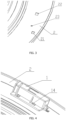
- Fig. 1 is a schematic diagram showing a fastener 1 according to a first embodiment of the present disclosure when the fastener is 1 fixed to a first fixing member.
- Fig. 2 is a diagram showing a perspective view of the fastener 1 shown in Fig. 1 .
- Fig. 3 is a schematic diagram showing configurations of fastening holes 21, 22 and a position limit hole 23 of the first fixing member.
- the fastener 1 includes a position limit column 13, an elastic member 14, and at least one fastening hook 11.
- the elastic member 14 is disposed at a bottom portion of the position limit column 13.
- the first fixing member includes a fastening hole 21 disposed at a portion corresponding to the fastening hook 11.
- the first fixing member includes a position limit hole 23 disposed at a portion corresponding to the position limit column 13.
- the first fixing member may be provided by a bottom panel 2.
- the fastening hook 11 When the fastening hook 11 is placed in the vicinity of the fastening hole 21, the position limit column 13 is pressed against the bottom panel 2 and the elastic member is in a deformed state. Thus, the elastic member generates an elastic force in a rebound direction.
- the fastener 1 moves to a predetermined position, the position limit column 13 falls in to the position limit hole 23 under the elastic force.
- the fastener 1 is fixed at a proper position.
- the fastening hook 11 engages with the fastening hole 21 and the fastener 1 is fixedly connected with the first fixing member 2. As described above, when fixedly connecting the fastener 1 with the first fixing member 2, no screws are used.
- the fastener has a simple structure. Further, when replacing the fastener, for example, equipping and dismounting the fastener, an operator does not need any professional tools. Thus, the whole work can be more convenient and efficient, and can reduce manpower cost and time cost.
- the first fixing member (for example, bottom panel 2) includes two fastening holes.
- One fastening hole 21 is disposed at a portion of the bottom panel 2 corresponding to the fastening hook 11.
- the other fastening hole 22 is disposed at a portion of the bottom panel 2 corresponding to the fastening hook 12.
- the number of the fastening hooks may be greater than two. Multiple fastening hooks may be distributed at different portions of the fastener 1 and the fastening hooks are uniformly distributed for ensuring a uniform force receiving. With this configuration, the fastener 1 can be fixed to the bottom panel 2 more tightly.
- the position limit column 13 may be disposed between the fastening hook 11 and the fastening hook 12.
- the position limit column 13 is disposed at a center portion between fastening hook 11 and the fastening hook 12.
- the position limit column 13 cooperates with the position limit hole 23 for fixedly connecting a position of the fastener 1.
- the fastener 1 receives a force from the position limit column 13 more uniformly for fixedly connecting the fastener 1.
- the fastener 1 can be more tightly fixed at a proper position.
- the elastic member is provided by an elastic plate 14.
- One end of the elastic plate 14 is fixed to the fastener 1.
- the position limit column 13 is disposed.
- a free end of the fastening hook 11 may be disposed in a first direction (that is, mounting direction).
- the first direction is identical to a moving direction of the fastener 1 when equipping the fastener 1.
- the fastening hook 11 can be smoothly engaged with the fastening hole 21, and the fastener can be more tightly fixed to the bottom panel.
- Fig. 4 is a schematic diagram showing the fastener 1 shown in Fig. 1 when the fastener 1 is in an equipped state.
- Fig. 5 is a diagram showing a perspective view of multiple fasteners and the first fixing member (for example, bottom panel 2) when they are fixed together.
- the fastening hook 11 and the fastening hook 12 are respectively positioned in the vicinity of the fastening hole 21 and in the vicinity of the fastening hole 22.
- the elastic plate 14 since the position limit column 13 is pressed against the bottom panel 2, the elastic plate 14 is in a deformed state.
- the elastic plate 14 generates an elastic force in a rebound direction.
- the position of the fastener 1 is referred to as the predetermined position.
- the position limit column 13 falls into the position limit hole 23 under the elastic force of the elastic plate 14.
- the fastening hook 11 is engaged with the fastening hole 21, and the fastening hook 12 is engaged with the fastening hole 22.
- the fastener 1 is fixedly connected with the bottom panel 2.
- mounting of the fastener does not use any professional tools, and does not need screw multiple screws between the bottom panel and the fastener.
- the whole mounting work or dismounting work can be more convenient and efficient, and manpower cost and time cost can be reduced. Accordingly, working efficiency can be improved.
- the position limit column 13 is departed from the position limit hole 23 using any method.
- the elastic plate 14 is levered up at an opposite side of the position limit column 13 using finger or other proper tools.
- the position limit column 13 is pressed at one side using any proper tools so that the position limit column 13 departs from the position limit hole 23.
- the fastener 1 is moved in the second direction (that is, dismounting direction) opposite to the first direction. With this moving, the engagement between the fastening hook 11 and the fastening hole 21 is released, and the engagement between the fastening hook 12 and the fastening hole 22 is released. At the end, the fastener 1 can be removed from the bottom panel 2.
- the position limit column 13 and the elastic plate 14 are formed integrally with each other. More preferably, the whole fastener 1 is formed as a single piece. When forming as a single piece, the fastener has a more simple structure, and the mounting and dismounting becomes more convenient and efficient.
- the fastener includes the position limit column, the elastic member, and at least one fastening hook.
- the elastic member is disposed at the bottom portion of the position limit column.
- the first fixing member includes the fastening hole disposed at the portion corresponding to the fastening hook, and the first fixing member includes the position limit hole disposed at the portion corresponding to the position limit column.
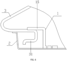
- Fig. 6 is a diagram showing a partial sectional view of a fastener assembly according to a second embodiment of the present disclosure.
- Fig. 7 is a diagram showing a perspective view of the second fixing member.
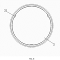
- Fig. 8 is a diagram showing a front view of the second fixing member.
- the fastener assembly includes a first fixing member 2, a second fixing member 3, and multiple fasteners 1 according to the first embodiment.
- a configuration of the fastener 1 and mounting or dismounting of the fastener 1 to or from the first fixing member 2 are similar to the first embodiment, and details are described in the above-described first embodiment.
- a protruded portion 31 is disposed at a periphery of the second fixing member 3 and the protruded portion 31 is bent toward an inner direction and corresponds to the fastener 1, and the protruded portion cooperates with the fastener 1 for fixedly connecting the first fixing member with the second fixing member.
- the fastener assembly is a lamp
- the second fixing member is a lamp cover
- the first fixing member is a bottom panel 2.
- the fastener assembly may be a display apparatus
- the first fixing member may be a display monitor main body
- the second fixing member may be an outer cover. Any other apparatuses having the structures disclosed in the present disclosure are included in the scope of the present disclosure.
- the fastener 1 includes a lip at a side away from the first fixing member.
- the lip engages with the protruded portion for fixedly connecting the first fixing member with the second fixing member.
- the fastener 1 includes the lip 15 at a side away from the bottom panel 2, and the lip 15 engages with the protruded portion 31 of the lamp cover 3 for fixedly connecting the bottom panel 2 with the lamp cover 3.
- the lamp cover 3 is placed on the bottom panel 2 so that the fastener 1 is displaced from the protruded portion 31. Then, the lamp cover 3 is rotated so that the lip 15 engages with the protruded portion 31 for fixedly connecting the bottom panel 2 with the lamp cover 3.
- the number of the fasteners 1 is three, and the number of the protruded portions 31 is three.
- the number of the fasteners 1 may be three to six, and the number of the protruded portions 31 may be three to six.
- the number of the fasteners 1 and the number of the protruded portions 31 may also be increased corresponding to actual needs.
- the fastener 1 is formed integrally with the lip 15, and the lamp cover 3 is formed integrally with the protruded portion 31. By forming integrally, the lamp can have a more simple structure and mounting and dismounting becomes convenient and efficient.
- the fastener includes the position limit column, the elastic member, and at least one fastening hook.
- the elastic member is disposed at the bottom portion of the position limit column.
- the first fixing member includes the fastening hole disposed at the portion corresponding to the fastening hook, and the first fixing member includes the position limit hole disposed at the portion corresponding to the position limit column.
Landscapes
- Engineering & Computer Science (AREA)
- General Engineering & Computer Science (AREA)
- Mechanical Engineering (AREA)
- Insertion Pins And Rivets (AREA)
- Securing Globes, Refractors, Reflectors Or The Like (AREA)
- Buckles (AREA)
- Connection Of Plates (AREA)
Claims (9)
- Befestigungsanordnung, umfassend
eine Befestigung (1) und ein erstes Fixierungselement (2), wobei die Befestigung (1) umfasst:eine erste Platte, die sich in einer ersten Ebene erstreckt und einen Positionsbegrenzungsholm (13), ein elastisches Element (14) und mindestens einen Befestigungshaken (11, 12) umfasst, wobei der mindestens eine Befestigungshaken (11, 12) zwei Befestigungshaken (11, 12) umfasst, undeine Seitenplatte, die an einem Ende der Befestigung (1) gebildet ist und sich in einer zweiten Ebene erstreckt, wobei sich die erste und die zweite Ebene gegenseitig schneiden,wobeidas elastische Element (14) an einem unteren Abschnitt dem Positionsbegrenzungsholm (13) angeordnet ist,ein erstes Fixierungselement (2) zwei Befestigungslöcher (21, 22) umfasst, die in einem Abschnitt angeordnet sind, der den Befestigungshaken (11, 12) entspricht,das erste Fixierungselement (2) ferner ein Positionsbegrenzungsloch (23) umfasst, das an einem Abschnitt angeordnet ist, der dem Positionsbegrenzungsholm (13) entspricht,wenn die Befestigungshaken (11, 12) in der Nähe der Befestigungslöcher (21, 22) platziert sind, der Positionsbegrenzungsholm (13) gegen das erste Fixierungselement (2) gedrückt wird, um eine Verformung des elastischen Elements (14) zu bewirken, und das elastische Element (14) eine elastische Kraft in einer Rückstoßrichtung erzeugt,wenn sich die Befestigung (1) zu einer vorbestimmten Position bewegt, der Positionsbegrenzungsholm (13) unter der Wirkung der elastischen Kraft in das Positionsbegrenzungsloch (23) fällt und die Befestigung (1) in einer geeigneten Position fixiert wird, undwenn der Positionsbegrenzungsholm (13) in das Positionsbegrenzungsloch (23) fällt, die Befestigungshaken (11, 12) in die Befestigungslöcher (21, 22) eingreifen und die Befestigung (1) fest mit dem ersten Fixierungselement (2) verbunden ist,dadurch gekennzeichnet, dass einer der beiden Befestigungshaken (11, 12) an einem Ende der Befestigung (1) und an der einen Seite der Seitenplatte entfernt von dem elastischen Element (14) angeordnet ist und der andere der beiden Befestigungshaken (11, 12) an dem anderen Ende der Befestigung (1) und an der anderen Seite der Seitenplatte angeordnet ist. - Befestigungsanordnung nach Anspruch 1, wobei der Positionsbegrenzungsholm (13) zwischen den beiden Befestigungshaken (11, 12) angeordnet ist.
- Befestigungsanordnung nach Anspruch 1, wobei ein freies Ende jedes der beiden Befestigungshaken (11, 12) in einer ersten Richtung angeordnet ist und die erste Richtung mit einer Montagerichtung der Befestigung (1) identisch ist.
- Befestigungsanordnung nach einem der Ansprüche 1 bis 3, wobei das elastische Element (14) eine elastische Platte (14) ist, ein Ende der elastischen Platte (14) an der Befestigung fixiert ist und der Positionsbegrenzungsholm (13) an dem anderen Ende der elastischen Platte (14) angeordnet ist.
- Befestigungsanordnung nach Anspruch 4, wobei der Positionsbegrenzungsholm (13) einstückig mit der elastischen Platte (14) gebildet ist.
- Befestigungsanordnung nach einem der Ansprüche 1 bis 5, wobei die Befestigung (1) als ein einziges Stück gebildet ist.
- Befestigungsanordnung nach einem der Ansprüche 1 bis 6, wobei die Befestigung ein zweites Fixierungselement (3) und mehrere der Befestigungen (1) umfasst, und
wobei ein vorstehender Abschnitt (31) an einem Umfang des zweiten Fixierungselements (3) angeordnet ist und der vorstehende Abschnitt (31) in eine innere Richtung gebogen ist und der Befestigung (1) entspricht, und der vorstehende Abschnitt (31) mit der Befestigung (1) zusammenwirkt, um das erste Fixierungselement (2) mit dem zweiten Fixierungselement (3) fest zu verbinden. - Befestigungsanordnung nach Anspruch 7, wobei die Befestigung (1) eine Lippe (15) an einer Seite aufweist, die von dem ersten Fixierungselement (2) entfernt ist, und die Lippe (15) mit dem vorstehenden Abschnitt (31) in Eingriff steht, um das erste Fixierungselement (2) mit dem zweiten Fixierungselement (3) fest zu verbinden.
- Befestigungsanordnung nach Anspruch 8, wobei die Befestigung (1) einstückig mit der Lippe (15) gebildet ist und das zweite Fixierungselement (3) einstückig mit dem vorstehenden Abschnitt (31) gebildet ist.
Applications Claiming Priority (2)
| Application Number | Priority Date | Filing Date | Title |
|---|---|---|---|
| CN201420584286.8U CN204084226U (zh) | 2014-10-10 | 2014-10-10 | 一种卡扣和卡扣装置 |
| PCT/CN2015/074691 WO2016054895A1 (zh) | 2014-10-10 | 2015-03-20 | 一种卡扣和卡扣组件 |
Publications (3)
| Publication Number | Publication Date |
|---|---|
| EP3205931A1 EP3205931A1 (de) | 2017-08-16 |
| EP3205931A4 EP3205931A4 (de) | 2018-05-30 |
| EP3205931B1 true EP3205931B1 (de) | 2024-06-19 |
Family
ID=52176941
Family Applications (1)
| Application Number | Title | Priority Date | Filing Date |
|---|---|---|---|
| EP15753303.5A Active EP3205931B1 (de) | 2014-10-10 | 2015-03-20 | Schnappverbindungsanordnung |
Country Status (6)
| Country | Link |
|---|---|
| US (1) | US9816690B2 (de) |
| EP (1) | EP3205931B1 (de) |
| JP (1) | JP6614680B2 (de) |
| KR (1) | KR20160058067A (de) |
| CN (1) | CN204084226U (de) |
| WO (1) | WO2016054895A1 (de) |
Families Citing this family (5)
| Publication number | Priority date | Publication date | Assignee | Title |
|---|---|---|---|---|
| CN204084226U (zh) * | 2014-10-10 | 2015-01-07 | 京东方光科技有限公司 | 一种卡扣和卡扣装置 |
| DE102016206107A1 (de) * | 2016-04-12 | 2017-10-12 | Robert Bosch Gmbh | Vorrichtung zur Befestigung einer Komponente |
| CN106163173A (zh) * | 2016-07-11 | 2016-11-23 | 南京恒慧智能科技有限公司 | 一种可快速拆卸装配的卡接结构 |
| CN109750785B (zh) * | 2019-03-13 | 2024-05-03 | 成都劲启家居有限公司 | 一种安装扣 |
| EP4386217A1 (de) * | 2022-12-14 | 2024-06-19 | Worxsafe AB | Befestigungsvorrichtung |
Family Cites Families (16)
| Publication number | Priority date | Publication date | Assignee | Title |
|---|---|---|---|---|
| US1334762A (en) * | 1919-04-07 | 1920-03-23 | Eugene A Kuen | Fastening device for automobile lamp closures |
| US3130949A (en) * | 1962-07-02 | 1964-04-28 | Century Lighting Inc | Support for lighting and building fixtures and the like |
| JPS6060811U (ja) * | 1983-10-04 | 1985-04-27 | 共和電器株式会社 | カバ−付放電灯のカバ−支持装置 |
| GB2234546B (en) * | 1989-08-01 | 1993-05-26 | Kentinental Eng | Fastening means |
| IT1302668B1 (it) * | 1998-10-14 | 2000-09-29 | Beghelli Spa | Apparecchio per illuminazione di sicurezza |
| JP2003346539A (ja) | 2002-05-27 | 2003-12-05 | Matsushita Electric Works Ltd | 照明器具 |
| CN2612210Y (zh) * | 2003-03-05 | 2004-04-14 | 鸿富锦精密工业(深圳)有限公司 | 散热器扣具 |
| US20050190573A1 (en) * | 2004-02-27 | 2005-09-01 | Schwab Leo F. | Releaseable fastening device |
| JP2005317335A (ja) * | 2004-04-28 | 2005-11-10 | Asahi Matsushita Electric Works Ltd | 照明器具 |
| US7448822B2 (en) * | 2006-03-15 | 2008-11-11 | The Boeing Company | Retaining member and method for use with a seat track |
| DE102010043545A1 (de) * | 2010-11-08 | 2012-05-10 | BSH Bosch und Siemens Hausgeräte GmbH | Beleuchtungseinrichtung für ein Großelektrogerät |
| CN102691983B (zh) * | 2011-03-21 | 2015-09-16 | 海洋王照明科技股份有限公司 | 卡扣连接装置及灯具 |
| CN102853388A (zh) * | 2011-06-30 | 2013-01-02 | 海洋王照明科技股份有限公司 | 一种灯具面罩固定结构及使用该固定结构的灯具 |
| CN202708652U (zh) * | 2012-05-21 | 2013-01-30 | 深圳市恒之源电器有限公司 | 一种多功能的led照明装置 |
| CN103453470A (zh) * | 2012-05-31 | 2013-12-18 | 海洋王(东莞)照明科技有限公司 | 一种灯具及其面盖防转结构 |
| CN204084226U (zh) * | 2014-10-10 | 2015-01-07 | 京东方光科技有限公司 | 一种卡扣和卡扣装置 |
-
2014
- 2014-10-10 CN CN201420584286.8U patent/CN204084226U/zh not_active Expired - Lifetime
-
2015
- 2015-03-20 KR KR1020157023707A patent/KR20160058067A/ko not_active Ceased
- 2015-03-20 EP EP15753303.5A patent/EP3205931B1/de active Active
- 2015-03-20 JP JP2017538278A patent/JP6614680B2/ja active Active
- 2015-03-20 WO PCT/CN2015/074691 patent/WO2016054895A1/zh not_active Ceased
- 2015-03-20 US US14/771,766 patent/US9816690B2/en active Active
Also Published As
| Publication number | Publication date |
|---|---|
| KR20160058067A (ko) | 2016-05-24 |
| JP2017531303A (ja) | 2017-10-19 |
| US9816690B2 (en) | 2017-11-14 |
| US20160298830A1 (en) | 2016-10-13 |
| WO2016054895A1 (zh) | 2016-04-14 |
| CN204084226U (zh) | 2015-01-07 |
| EP3205931A1 (de) | 2017-08-16 |
| JP6614680B2 (ja) | 2019-12-04 |
| EP3205931A4 (de) | 2018-05-30 |
Similar Documents
| Publication | Publication Date | Title |
|---|---|---|
| US9816690B2 (en) | Fastener and fastener assembly | |
| JP6113757B2 (ja) | 自己インデクシングナットプレート | |
| US20150022964A1 (en) | Mounting apparatus assembly | |
| EP3282131A1 (de) | Aufbau von deckenlüfterschaufeln und deckenlüfter | |
| KR101582894B1 (ko) | 자동차용 고정구 | |
| TW201913652A (zh) | 固持裝置 | |
| TW201303174A (zh) | 螺絲結構 | |
| CN110888509A (zh) | 一种服务器及其免紧固拆装机箱 | |
| US9060426B2 (en) | Securing mechanism | |
| EP3683517A1 (de) | Montagestruktur einer seitenplatte und inneneinheit damit | |
| US9801299B1 (en) | Server disk drive holder assembly | |
| CN104977994B (zh) | 卡扣模组及其所适用的机箱 | |
| US8749972B2 (en) | Mounting apparatus for power supply | |
| JP5527012B2 (ja) | ネジ仮止め部材および電子部品 | |
| US12044387B1 (en) | Backlight module, assembly method of backlight module and display | |
| TW201315339A (zh) | 支撐裝置 | |
| TWI516679B (zh) | 風扇的安裝結構及風扇裝置 | |
| CN207051801U (zh) | 硬盘支架 | |
| CN214465417U (zh) | 可快速拆卸的紧固机构 | |
| CN202581666U (zh) | 空调器电控板安装结构 | |
| CN204628987U (zh) | 一种支撑装置 | |
| CN110513382B (zh) | 一种前装螺母结构 | |
| CN104896830A (zh) | 冰箱及其风道面板 | |
| EP3382276A1 (de) | Leuchte | |
| CN213782292U (zh) | 连接组件及电池系统 |
Legal Events
| Date | Code | Title | Description |
|---|---|---|---|
| STAA | Information on the status of an ep patent application or granted ep patent |
Free format text: STATUS: THE INTERNATIONAL PUBLICATION HAS BEEN MADE |
|
| PUAI | Public reference made under article 153(3) epc to a published international application that has entered the european phase |
Free format text: ORIGINAL CODE: 0009012 |
|
| STAA | Information on the status of an ep patent application or granted ep patent |
Free format text: STATUS: REQUEST FOR EXAMINATION WAS MADE |
|
| 17P | Request for examination filed |
Effective date: 20150831 |
|
| AK | Designated contracting states |
Kind code of ref document: A1 Designated state(s): AL AT BE BG CH CY CZ DE DK EE ES FI FR GB GR HR HU IE IS IT LI LT LU LV MC MK MT NL NO PL PT RO RS SE SI SK SM TR |
|
| AX | Request for extension of the european patent |
Extension state: BA ME |
|
| DAV | Request for validation of the european patent (deleted) | ||
| DAX | Request for extension of the european patent (deleted) | ||
| A4 | Supplementary search report drawn up and despatched |
Effective date: 20180503 |
|
| RIC1 | Information provided on ipc code assigned before grant |
Ipc: F16B 17/00 20060101ALI20180425BHEP Ipc: F16B 2/22 20060101ALN20180425BHEP Ipc: F21V 17/16 20060101AFI20180425BHEP Ipc: F16B 21/02 20060101ALI20180425BHEP |
|
| STAA | Information on the status of an ep patent application or granted ep patent |
Free format text: STATUS: EXAMINATION IS IN PROGRESS |
|
| 17Q | First examination report despatched |
Effective date: 20210423 |
|
| RIC1 | Information provided on ipc code assigned before grant |
Ipc: F16B 2/22 20060101ALN20230427BHEP Ipc: F16B 21/02 20060101ALI20230427BHEP Ipc: F16B 17/00 20060101ALI20230427BHEP Ipc: F21V 17/16 20060101AFI20230427BHEP |
|
| GRAP | Despatch of communication of intention to grant a patent |
Free format text: ORIGINAL CODE: EPIDOSNIGR1 |
|
| STAA | Information on the status of an ep patent application or granted ep patent |
Free format text: STATUS: GRANT OF PATENT IS INTENDED |
|
| RIC1 | Information provided on ipc code assigned before grant |
Ipc: F16B 2/22 20060101ALN20240124BHEP Ipc: F16B 21/02 20060101ALI20240124BHEP Ipc: F16B 17/00 20060101ALI20240124BHEP Ipc: F21V 17/16 20060101AFI20240124BHEP |
|
| INTG | Intention to grant announced |
Effective date: 20240214 |
|
| GRAS | Grant fee paid |
Free format text: ORIGINAL CODE: EPIDOSNIGR3 |
|
| GRAA | (expected) grant |
Free format text: ORIGINAL CODE: 0009210 |
|
| STAA | Information on the status of an ep patent application or granted ep patent |
Free format text: STATUS: THE PATENT HAS BEEN GRANTED |
|
| AK | Designated contracting states |
Kind code of ref document: B1 Designated state(s): AL AT BE BG CH CY CZ DE DK EE ES FI FR GB GR HR HU IE IS IT LI LT LU LV MC MK MT NL NO PL PT RO RS SE SI SK SM TR |
|
| REG | Reference to a national code |
Ref country code: GB Ref legal event code: FG4D |
|
| REG | Reference to a national code |
Ref country code: CH Ref legal event code: EP |
|
| REG | Reference to a national code |
Ref country code: DE Ref legal event code: R096 Ref document number: 602015089020 Country of ref document: DE |
|
| PG25 | Lapsed in a contracting state [announced via postgrant information from national office to epo] |
Ref country code: BG Free format text: LAPSE BECAUSE OF FAILURE TO SUBMIT A TRANSLATION OF THE DESCRIPTION OR TO PAY THE FEE WITHIN THE PRESCRIBED TIME-LIMIT Effective date: 20240619 |
|
| PG25 | Lapsed in a contracting state [announced via postgrant information from national office to epo] |
Ref country code: FI Free format text: LAPSE BECAUSE OF FAILURE TO SUBMIT A TRANSLATION OF THE DESCRIPTION OR TO PAY THE FEE WITHIN THE PRESCRIBED TIME-LIMIT Effective date: 20240619 Ref country code: HR Free format text: LAPSE BECAUSE OF FAILURE TO SUBMIT A TRANSLATION OF THE DESCRIPTION OR TO PAY THE FEE WITHIN THE PRESCRIBED TIME-LIMIT Effective date: 20240619 |
|
| REG | Reference to a national code |
Ref country code: LT Ref legal event code: MG9D |
|
| PG25 | Lapsed in a contracting state [announced via postgrant information from national office to epo] |
Ref country code: GR Free format text: LAPSE BECAUSE OF FAILURE TO SUBMIT A TRANSLATION OF THE DESCRIPTION OR TO PAY THE FEE WITHIN THE PRESCRIBED TIME-LIMIT Effective date: 20240920 |
|
| REG | Reference to a national code |
Ref country code: NL Ref legal event code: MP Effective date: 20240619 |
|
| PG25 | Lapsed in a contracting state [announced via postgrant information from national office to epo] |
Ref country code: LV Free format text: LAPSE BECAUSE OF FAILURE TO SUBMIT A TRANSLATION OF THE DESCRIPTION OR TO PAY THE FEE WITHIN THE PRESCRIBED TIME-LIMIT Effective date: 20240619 |
|
| PG25 | Lapsed in a contracting state [announced via postgrant information from national office to epo] |
Ref country code: NO Free format text: LAPSE BECAUSE OF FAILURE TO SUBMIT A TRANSLATION OF THE DESCRIPTION OR TO PAY THE FEE WITHIN THE PRESCRIBED TIME-LIMIT Effective date: 20240919 Ref country code: LV Free format text: LAPSE BECAUSE OF FAILURE TO SUBMIT A TRANSLATION OF THE DESCRIPTION OR TO PAY THE FEE WITHIN THE PRESCRIBED TIME-LIMIT Effective date: 20240619 Ref country code: HR Free format text: LAPSE BECAUSE OF FAILURE TO SUBMIT A TRANSLATION OF THE DESCRIPTION OR TO PAY THE FEE WITHIN THE PRESCRIBED TIME-LIMIT Effective date: 20240619 Ref country code: GR Free format text: LAPSE BECAUSE OF FAILURE TO SUBMIT A TRANSLATION OF THE DESCRIPTION OR TO PAY THE FEE WITHIN THE PRESCRIBED TIME-LIMIT Effective date: 20240920 Ref country code: FI Free format text: LAPSE BECAUSE OF FAILURE TO SUBMIT A TRANSLATION OF THE DESCRIPTION OR TO PAY THE FEE WITHIN THE PRESCRIBED TIME-LIMIT Effective date: 20240619 Ref country code: BG Free format text: LAPSE BECAUSE OF FAILURE TO SUBMIT A TRANSLATION OF THE DESCRIPTION OR TO PAY THE FEE WITHIN THE PRESCRIBED TIME-LIMIT Effective date: 20240619 Ref country code: RS Free format text: LAPSE BECAUSE OF FAILURE TO SUBMIT A TRANSLATION OF THE DESCRIPTION OR TO PAY THE FEE WITHIN THE PRESCRIBED TIME-LIMIT Effective date: 20240919 |
|
| PG25 | Lapsed in a contracting state [announced via postgrant information from national office to epo] |
Ref country code: NL Free format text: LAPSE BECAUSE OF FAILURE TO SUBMIT A TRANSLATION OF THE DESCRIPTION OR TO PAY THE FEE WITHIN THE PRESCRIBED TIME-LIMIT Effective date: 20240619 |
|
| REG | Reference to a national code |
Ref country code: AT Ref legal event code: MK05 Ref document number: 1696116 Country of ref document: AT Kind code of ref document: T Effective date: 20240619 |
|
| PG25 | Lapsed in a contracting state [announced via postgrant information from national office to epo] |
Ref country code: NL Free format text: LAPSE BECAUSE OF FAILURE TO SUBMIT A TRANSLATION OF THE DESCRIPTION OR TO PAY THE FEE WITHIN THE PRESCRIBED TIME-LIMIT Effective date: 20240619 |
|
| PG25 | Lapsed in a contracting state [announced via postgrant information from national office to epo] |
Ref country code: PT Free format text: LAPSE BECAUSE OF FAILURE TO SUBMIT A TRANSLATION OF THE DESCRIPTION OR TO PAY THE FEE WITHIN THE PRESCRIBED TIME-LIMIT Effective date: 20241021 |
|
| PG25 | Lapsed in a contracting state [announced via postgrant information from national office to epo] |
Ref country code: PT Free format text: LAPSE BECAUSE OF FAILURE TO SUBMIT A TRANSLATION OF THE DESCRIPTION OR TO PAY THE FEE WITHIN THE PRESCRIBED TIME-LIMIT Effective date: 20241021 |
|
| PG25 | Lapsed in a contracting state [announced via postgrant information from national office to epo] |
Ref country code: PL Free format text: LAPSE BECAUSE OF FAILURE TO SUBMIT A TRANSLATION OF THE DESCRIPTION OR TO PAY THE FEE WITHIN THE PRESCRIBED TIME-LIMIT Effective date: 20240619 |
|
| PG25 | Lapsed in a contracting state [announced via postgrant information from national office to epo] |
Ref country code: EE Free format text: LAPSE BECAUSE OF FAILURE TO SUBMIT A TRANSLATION OF THE DESCRIPTION OR TO PAY THE FEE WITHIN THE PRESCRIBED TIME-LIMIT Effective date: 20240619 |
|
| PG25 | Lapsed in a contracting state [announced via postgrant information from national office to epo] |
Ref country code: IS Free format text: LAPSE BECAUSE OF FAILURE TO SUBMIT A TRANSLATION OF THE DESCRIPTION OR TO PAY THE FEE WITHIN THE PRESCRIBED TIME-LIMIT Effective date: 20241019 Ref country code: AT Free format text: LAPSE BECAUSE OF FAILURE TO SUBMIT A TRANSLATION OF THE DESCRIPTION OR TO PAY THE FEE WITHIN THE PRESCRIBED TIME-LIMIT Effective date: 20240619 |
|
| PG25 | Lapsed in a contracting state [announced via postgrant information from national office to epo] |
Ref country code: CZ Free format text: LAPSE BECAUSE OF FAILURE TO SUBMIT A TRANSLATION OF THE DESCRIPTION OR TO PAY THE FEE WITHIN THE PRESCRIBED TIME-LIMIT Effective date: 20240619 |
|
| PG25 | Lapsed in a contracting state [announced via postgrant information from national office to epo] |
Ref country code: RO Free format text: LAPSE BECAUSE OF FAILURE TO SUBMIT A TRANSLATION OF THE DESCRIPTION OR TO PAY THE FEE WITHIN THE PRESCRIBED TIME-LIMIT Effective date: 20240619 Ref country code: SK Free format text: LAPSE BECAUSE OF FAILURE TO SUBMIT A TRANSLATION OF THE DESCRIPTION OR TO PAY THE FEE WITHIN THE PRESCRIBED TIME-LIMIT Effective date: 20240619 |
|
| PG25 | Lapsed in a contracting state [announced via postgrant information from national office to epo] |
Ref country code: ES Free format text: LAPSE BECAUSE OF FAILURE TO SUBMIT A TRANSLATION OF THE DESCRIPTION OR TO PAY THE FEE WITHIN THE PRESCRIBED TIME-LIMIT Effective date: 20240619 Ref country code: SM Free format text: LAPSE BECAUSE OF FAILURE TO SUBMIT A TRANSLATION OF THE DESCRIPTION OR TO PAY THE FEE WITHIN THE PRESCRIBED TIME-LIMIT Effective date: 20240619 |
|
| PG25 | Lapsed in a contracting state [announced via postgrant information from national office to epo] |
Ref country code: SM Free format text: LAPSE BECAUSE OF FAILURE TO SUBMIT A TRANSLATION OF THE DESCRIPTION OR TO PAY THE FEE WITHIN THE PRESCRIBED TIME-LIMIT Effective date: 20240619 Ref country code: SK Free format text: LAPSE BECAUSE OF FAILURE TO SUBMIT A TRANSLATION OF THE DESCRIPTION OR TO PAY THE FEE WITHIN THE PRESCRIBED TIME-LIMIT Effective date: 20240619 Ref country code: RO Free format text: LAPSE BECAUSE OF FAILURE TO SUBMIT A TRANSLATION OF THE DESCRIPTION OR TO PAY THE FEE WITHIN THE PRESCRIBED TIME-LIMIT Effective date: 20240619 Ref country code: PL Free format text: LAPSE BECAUSE OF FAILURE TO SUBMIT A TRANSLATION OF THE DESCRIPTION OR TO PAY THE FEE WITHIN THE PRESCRIBED TIME-LIMIT Effective date: 20240619 Ref country code: IS Free format text: LAPSE BECAUSE OF FAILURE TO SUBMIT A TRANSLATION OF THE DESCRIPTION OR TO PAY THE FEE WITHIN THE PRESCRIBED TIME-LIMIT Effective date: 20241019 Ref country code: ES Free format text: LAPSE BECAUSE OF FAILURE TO SUBMIT A TRANSLATION OF THE DESCRIPTION OR TO PAY THE FEE WITHIN THE PRESCRIBED TIME-LIMIT Effective date: 20240619 Ref country code: EE Free format text: LAPSE BECAUSE OF FAILURE TO SUBMIT A TRANSLATION OF THE DESCRIPTION OR TO PAY THE FEE WITHIN THE PRESCRIBED TIME-LIMIT Effective date: 20240619 Ref country code: CZ Free format text: LAPSE BECAUSE OF FAILURE TO SUBMIT A TRANSLATION OF THE DESCRIPTION OR TO PAY THE FEE WITHIN THE PRESCRIBED TIME-LIMIT Effective date: 20240619 Ref country code: AT Free format text: LAPSE BECAUSE OF FAILURE TO SUBMIT A TRANSLATION OF THE DESCRIPTION OR TO PAY THE FEE WITHIN THE PRESCRIBED TIME-LIMIT Effective date: 20240619 |
|
| PG25 | Lapsed in a contracting state [announced via postgrant information from national office to epo] |
Ref country code: IT Free format text: LAPSE BECAUSE OF FAILURE TO SUBMIT A TRANSLATION OF THE DESCRIPTION OR TO PAY THE FEE WITHIN THE PRESCRIBED TIME-LIMIT Effective date: 20240619 |
|
| REG | Reference to a national code |
Ref country code: DE Ref legal event code: R097 Ref document number: 602015089020 Country of ref document: DE |
|
| PGFP | Annual fee paid to national office [announced via postgrant information from national office to epo] |
Ref country code: DE Payment date: 20250319 Year of fee payment: 11 |
|
| PG25 | Lapsed in a contracting state [announced via postgrant information from national office to epo] |
Ref country code: DK Free format text: LAPSE BECAUSE OF FAILURE TO SUBMIT A TRANSLATION OF THE DESCRIPTION OR TO PAY THE FEE WITHIN THE PRESCRIBED TIME-LIMIT Effective date: 20240619 |
|
| PLBE | No opposition filed within time limit |
Free format text: ORIGINAL CODE: 0009261 |
|
| STAA | Information on the status of an ep patent application or granted ep patent |
Free format text: STATUS: NO OPPOSITION FILED WITHIN TIME LIMIT |
|
| 26N | No opposition filed |
Effective date: 20250320 |
|
| PG25 | Lapsed in a contracting state [announced via postgrant information from national office to epo] |
Ref country code: SE Free format text: LAPSE BECAUSE OF FAILURE TO SUBMIT A TRANSLATION OF THE DESCRIPTION OR TO PAY THE FEE WITHIN THE PRESCRIBED TIME-LIMIT Effective date: 20240619 |
|
| PG25 | Lapsed in a contracting state [announced via postgrant information from national office to epo] |
Ref country code: MC Free format text: LAPSE BECAUSE OF FAILURE TO SUBMIT A TRANSLATION OF THE DESCRIPTION OR TO PAY THE FEE WITHIN THE PRESCRIBED TIME-LIMIT Effective date: 20240619 |
|
| REG | Reference to a national code |
Ref country code: CH Ref legal event code: H13 Free format text: ST27 STATUS EVENT CODE: U-0-0-H10-H13 (AS PROVIDED BY THE NATIONAL OFFICE) Effective date: 20251023 |
|
| PG25 | Lapsed in a contracting state [announced via postgrant information from national office to epo] |
Ref country code: LU Free format text: LAPSE BECAUSE OF NON-PAYMENT OF DUE FEES Effective date: 20250320 |
|
| GBPC | Gb: european patent ceased through non-payment of renewal fee |
Effective date: 20250320 |
|
| REG | Reference to a national code |
Ref country code: BE Ref legal event code: MM Effective date: 20250331 |
|
| PG25 | Lapsed in a contracting state [announced via postgrant information from national office to epo] |
Ref country code: GB Free format text: LAPSE BECAUSE OF NON-PAYMENT OF DUE FEES Effective date: 20250320 |
|
| PG25 | Lapsed in a contracting state [announced via postgrant information from national office to epo] |
Ref country code: FR Free format text: LAPSE BECAUSE OF NON-PAYMENT OF DUE FEES Effective date: 20250331 |
|
| PG25 | Lapsed in a contracting state [announced via postgrant information from national office to epo] |
Ref country code: BE Free format text: LAPSE BECAUSE OF NON-PAYMENT OF DUE FEES Effective date: 20250331 |
|
| PG25 | Lapsed in a contracting state [announced via postgrant information from national office to epo] |
Ref country code: CH Free format text: LAPSE BECAUSE OF NON-PAYMENT OF DUE FEES Effective date: 20250331 |
|
| PG25 | Lapsed in a contracting state [announced via postgrant information from national office to epo] |
Ref country code: IE Free format text: LAPSE BECAUSE OF NON-PAYMENT OF DUE FEES Effective date: 20250320 |