EP3204792B1 - Verfahren zum bereitstellen von hinderniskarten für fahrzeuge - Google Patents
Verfahren zum bereitstellen von hinderniskarten für fahrzeuge Download PDFInfo
- Publication number
- EP3204792B1 EP3204792B1 EP16711551.8A EP16711551A EP3204792B1 EP 3204792 B1 EP3204792 B1 EP 3204792B1 EP 16711551 A EP16711551 A EP 16711551A EP 3204792 B1 EP3204792 B1 EP 3204792B1
- Authority
- EP
- European Patent Office
- Prior art keywords
- threshold value
- map
- environment
- obstacle
- vehicle
- Prior art date
- Legal status (The legal status is an assumption and is not a legal conclusion. Google has not performed a legal analysis and makes no representation as to the accuracy of the status listed.)
- Active
Links
Images

Classifications
-
- B—PERFORMING OPERATIONS; TRANSPORTING
- B60—VEHICLES IN GENERAL
- B60W—CONJOINT CONTROL OF VEHICLE SUB-UNITS OF DIFFERENT TYPE OR DIFFERENT FUNCTION; CONTROL SYSTEMS SPECIALLY ADAPTED FOR HYBRID VEHICLES; ROAD VEHICLE DRIVE CONTROL SYSTEMS FOR PURPOSES NOT RELATED TO THE CONTROL OF A PARTICULAR SUB-UNIT
- B60W40/00—Estimation or calculation of non-directly measurable driving parameters for road vehicle drive control systems not related to the control of a particular sub unit, e.g. by using mathematical models
- B60W40/02—Estimation or calculation of non-directly measurable driving parameters for road vehicle drive control systems not related to the control of a particular sub unit, e.g. by using mathematical models related to ambient conditions
- B60W40/04—Traffic conditions
-
- G—PHYSICS
- G08—SIGNALLING
- G08G—TRAFFIC CONTROL SYSTEMS
- G08G1/00—Traffic control systems for road vehicles
- G08G1/16—Anti-collision systems
-
- B—PERFORMING OPERATIONS; TRANSPORTING
- B60—VEHICLES IN GENERAL
- B60W—CONJOINT CONTROL OF VEHICLE SUB-UNITS OF DIFFERENT TYPE OR DIFFERENT FUNCTION; CONTROL SYSTEMS SPECIALLY ADAPTED FOR HYBRID VEHICLES; ROAD VEHICLE DRIVE CONTROL SYSTEMS FOR PURPOSES NOT RELATED TO THE CONTROL OF A PARTICULAR SUB-UNIT
- B60W40/00—Estimation or calculation of non-directly measurable driving parameters for road vehicle drive control systems not related to the control of a particular sub unit, e.g. by using mathematical models
- B60W40/02—Estimation or calculation of non-directly measurable driving parameters for road vehicle drive control systems not related to the control of a particular sub unit, e.g. by using mathematical models related to ambient conditions
-
- G—PHYSICS
- G01—MEASURING; TESTING
- G01S—RADIO DIRECTION-FINDING; RADIO NAVIGATION; DETERMINING DISTANCE OR VELOCITY BY USE OF RADIO WAVES; LOCATING OR PRESENCE-DETECTING BY USE OF THE REFLECTION OR RERADIATION OF RADIO WAVES; ANALOGOUS ARRANGEMENTS USING OTHER WAVES
- G01S15/00—Systems using the reflection or reradiation of acoustic waves, e.g. sonar systems
- G01S15/88—Sonar systems specially adapted for specific applications
- G01S15/93—Sonar systems specially adapted for specific applications for anti-collision purposes
- G01S15/931—Sonar systems specially adapted for specific applications for anti-collision purposes of land vehicles
-
- G—PHYSICS
- G06—COMPUTING OR CALCULATING; COUNTING
- G06V—IMAGE OR VIDEO RECOGNITION OR UNDERSTANDING
- G06V20/00—Scenes; Scene-specific elements
- G06V20/50—Context or environment of the image
- G06V20/56—Context or environment of the image exterior to a vehicle by using sensors mounted on the vehicle
- G06V20/58—Recognition of moving objects or obstacles, e.g. vehicles or pedestrians; Recognition of traffic objects, e.g. traffic signs, traffic lights or roads
-
- B—PERFORMING OPERATIONS; TRANSPORTING
- B60—VEHICLES IN GENERAL
- B60W—CONJOINT CONTROL OF VEHICLE SUB-UNITS OF DIFFERENT TYPE OR DIFFERENT FUNCTION; CONTROL SYSTEMS SPECIALLY ADAPTED FOR HYBRID VEHICLES; ROAD VEHICLE DRIVE CONTROL SYSTEMS FOR PURPOSES NOT RELATED TO THE CONTROL OF A PARTICULAR SUB-UNIT
- B60W2420/00—Indexing codes relating to the type of sensors based on the principle of their operation
- B60W2420/40—Photo, light or radio wave sensitive means, e.g. infrared sensors
- B60W2420/408—Radar; Laser, e.g. lidar
-
- B—PERFORMING OPERATIONS; TRANSPORTING
- B60—VEHICLES IN GENERAL
- B60W—CONJOINT CONTROL OF VEHICLE SUB-UNITS OF DIFFERENT TYPE OR DIFFERENT FUNCTION; CONTROL SYSTEMS SPECIALLY ADAPTED FOR HYBRID VEHICLES; ROAD VEHICLE DRIVE CONTROL SYSTEMS FOR PURPOSES NOT RELATED TO THE CONTROL OF A PARTICULAR SUB-UNIT
- B60W2420/00—Indexing codes relating to the type of sensors based on the principle of their operation
- B60W2420/54—Audio sensitive means, e.g. ultrasound
-
- B—PERFORMING OPERATIONS; TRANSPORTING
- B60—VEHICLES IN GENERAL
- B60W—CONJOINT CONTROL OF VEHICLE SUB-UNITS OF DIFFERENT TYPE OR DIFFERENT FUNCTION; CONTROL SYSTEMS SPECIALLY ADAPTED FOR HYBRID VEHICLES; ROAD VEHICLE DRIVE CONTROL SYSTEMS FOR PURPOSES NOT RELATED TO THE CONTROL OF A PARTICULAR SUB-UNIT
- B60W2520/00—Input parameters relating to overall vehicle dynamics
- B60W2520/06—Direction of travel
-
- B—PERFORMING OPERATIONS; TRANSPORTING
- B60—VEHICLES IN GENERAL
- B60W—CONJOINT CONTROL OF VEHICLE SUB-UNITS OF DIFFERENT TYPE OR DIFFERENT FUNCTION; CONTROL SYSTEMS SPECIALLY ADAPTED FOR HYBRID VEHICLES; ROAD VEHICLE DRIVE CONTROL SYSTEMS FOR PURPOSES NOT RELATED TO THE CONTROL OF A PARTICULAR SUB-UNIT
- B60W2554/00—Input parameters relating to objects
Definitions
- the invention relates to a method for providing an obstacle map and a correspondingly configured electronic control device.
- the detection of the surroundings of the vehicle is essential. In particular, it is usually necessary to determine which sections of the surroundings are not blocked by obstacles and are therefore unrestrictedly passable.
- the surroundings are recorded with various sensor systems such as camera networks, radar, lidar and ultrasonic sensors.
- an environment map often also referred to as an occupancy grid, is typically used as a model.
- An environment map includes environment data that result from the processing of sensor measurements of the environment and represent them.
- the environment data is usually arranged according to sections of the environment. Each section is assigned the environmental data resulting from measurements in this section.
- the environment data can include different types of information per cell, for example the probability of occupancy of the respective cell (i.e. the probability that the cell is occupied by an obstacle), the height of the obstacle, etc.
- Some driver assistance functions do not need the abstract occupancy probability as information for modeling the environment, but rather the information as to whether a section of the environment is occupied by an obstacle or not.
- An obstacle in a section means that the section of the surroundings cannot be driven on by the vehicle or only under certain conditions.
- an obstacle map is typically generated which comprises cells which are each assigned to sections of the surroundings of the vehicle and to which the information is assigned as to whether the corresponding section of the surroundings is occupied by an obstacle.
- relevant Section of the environment is occupied with an obstacle.
- the cells of the obstacle map typically correspond to the cells of the environment map and the assigned sections are the same.
- the information as to whether a section is occupied by an obstacle is determined by comparing the occupancy probability of the map of the surroundings assigned to the section with a threshold value.
- the obstacle height determined for the section can also be taken into account.
- the correct detection of the occupancy probability due to an obstacle in a section depends on the distance to the vehicle and the angle to the vehicle's longitudinal axis. For example, obstacles in front of the vehicle are more often not correctly recognized than obstacles to the side of the vehicle. Even with an accumulation of the occupancy probabilities determined one after the other in time, obstacles in the environment map are represented by different occupancy probabilities.
- the problem arises that obstacles that are insufficiently represented by occupancy probabilities due to the detection properties of the SFM are not recorded in the obstacle map.
- document DE 10 2011 081740 A1 relates to a driving environment recognition device capable of precisely recognizing a driving environment of a vehicle.
- An occupancy grid map storing an occupancy probability of each obstacle for own vehicle travel for each cell of the occupancy grid map is generated, and the occupancy probability for each cell is updated.
- the invention is based on the object of solving the problem explained above.
- One aspect of the invention relates to a method for providing an obstacle map for driving functions and driver assistance systems of a vehicle, the obstacle map comprising cells which are each assigned to sections of the surroundings of the vehicle and to which the information is assigned as to whether the corresponding section of the surroundings with an obstacle is occupied;
- the method comprises: providing a map of the surroundings, the map of the surroundings comprising cells which are each assigned to sections of the surroundings of the vehicle and to which an obstacle probability is assigned which represents the probability that the corresponding section of the surroundings is occupied by an obstacle and which results from the processing of sensor measurements of the surroundings of the vehicle; Providing a threshold value specification; wherein the threshold value specification for cells of the environment map specifies different threshold values; the threshold value rule being determined as a function of the trajectory, in particular a part of the previous trajectory, of the vehicle; Determination of the obstacle map based on the environment map and depending on the threshold value rule.
- the threshold value rule can include an explicit specification of threshold values for each cell of the environment map (also called threshold value map) or be represented in a closed form (formula) from which the threshold values for individual cells of the environment map can be determined.
- the threshold map is also called the exploration grid.
- Sensor measured values from several sensor systems can be included in the provision of the environment map, for example measurements from camera systems and ultrasound systems.
- the threshold value rule can take into account the detection properties (in particular direction and distance dependency) of the sensor system of the vehicle with which the occupancy probabilities of the environmental sections are determined.
- a constant threshold value as in the prior art, but rather a threshold value which varies in a segment-related (or cell-related) manner.
- the variation of the threshold value can be selected in such a way that the different detection properties of obstacles of the vehicle's sensor system are taken into account.
- a high threshold value is selected for those sections for which the detection properties of the sensor Represent obstacles with a high probability of being occupied.
- a lower threshold value is chosen for those sections in which obstacles are represented by lower occupancy probabilities.
- the threshold values for the sections predetermined by the threshold value pattern can depend on the driving function that is carried out based on the obstacle map.
- the vehicle's trajectory determines for which sections the sensor properties have an effect, i.e. in which sections of the environment obstacles are represented with a high probability of occupancy and in which sections obstacles are represented with a low probability of occupancy.
- the threshold value rule for sections of the surroundings in the direction of travel in front of the vehicle will set a lower threshold value than for sections which the previous travel trajectory passed laterally.
- a threshold value pattern is repeatedly taken into account to determine the threshold value rule; wherein the threshold value pattern indicates different threshold value increments for different cells from a group of cells.
- the number of the group of cells can be smaller than the number of cells on the map of the surroundings.
- the threshold value pattern can be a threshold value pattern card which specifies threshold value increments for individual cells.
- the threshold values which the pattern specifies advantageously follow a Gaussian function or a linear function.
- the threshold value pattern reproduces the obstacle detection properties of the sensor system in the case of a single measurement (whereby a single measurement is understood here as a data basis which updates the environment map and can combine several raw measurements).
- the threshold value pattern can also take into account the properties of various sensor systems, for example SFM camera systems and ultrasound. Complex threshold value patterns can arise from this.
- the threshold value pattern is typically applied repeatedly or taken into account unchanged.
- the starting point can be a predefined start threshold value specification.
- the threshold value pattern is repeatedly added to this, depending on the trajectory of the vehicle.
- the threshold value of individual cells of the environment map can be limited to a maximum value, for example 0.9.
- the incremental further development of the threshold value rule has the advantage that the previous threshold value rule can be used for each successive determination of the obstacle map. Only the threshold value pattern corresponding to the current vehicle position is added to the last determined threshold value rule. The new vehicle position can also be reflected by shifting the map or its content.
- the accumulation (or the provision of the updated threshold value pattern) can take place in the same time segments or, if the familiarization is dependent on the covering of a route, after predetermined distances Driving trajectory can be carried out.
- One or more considerations or accumulations (additions) of the threshold value pattern can be undertaken between the determination of two obstacle maps in order to determine the threshold value rule then to be applied. This can depend on the number of incorporation of new sensor measurements (i.e. their newly recognized occupancy probabilities of the sections of the environment). Likewise, the threshold value pattern, in particular the level of the threshold value increments, can depend on the number of updates to the map of the surroundings by means of new sensor measurements of the surroundings.
- the threshold value pattern can be taken into account when determining the threshold value rule depending on the position and / or orientation of the vehicle in the map of the surroundings. This means that when the threshold value pattern is applied to the start threshold value map, the threshold value increments to be added in the individual cells of the threshold value map (based on the specifications of the threshold value pattern) are determined on the basis of the vehicle position.
- the threshold value pattern has a reference point, for example the symmetry point of the pattern (and possibly a reference direction), which is oriented to the vehicle position (and possibly the vehicle orientation).
- cells of the environment map are each assigned the same section of the environment as cells of the obstacle map; wherein the information for a cell of the obstacle map is obtained by comparing the occupancy probability of the corresponding cell of the environment map with a threshold value specified for the corresponding cell of the environment map in accordance with the threshold value rule.
- the obstacle map and the environment map thus correspond to the cell structure.
- control device for vehicles, the control device being set up to carry out one of the methods described above.
- the control device can be a microcontroller, a CPU, an ASIC or a RISC.
- Another aspect of the invention relates to a vehicle, in particular a passenger car, comprising the control device.
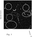
- Fig. 2 shows the measurement diagram of an environment map 1 according to an embodiment.
- the map of the surroundings comprises 256x256 cells, the assigned occupancy probability is shown on the basis of gray levels.
- White means that the corresponding section of the area was recorded as unoccupied, i.e. the occupancy probability was determined to be 0%.
- Gray means that no statement can be made about the occupancy, i.e. there is an occupancy probability of 50%.
- Black means that there is an occupancy, i.e. the cell has an occupancy probability of 100%.
- the majority of the cells are assigned an unknown occupancy probability.
- the measurements were carried out from vehicle 2 with the aid of cameras in the vehicle and an SFM method.
- the occupancy probabilities and height information determined for the sections of the surroundings are shown in the measurement diagram of Fig. 2 only the occupancy information is shown.
- vehicle 2 the rear axle is symbolized by the crossbar.
- the previous trajectory of the vehicle 2 moving forward can be seen from the white lane 3.
- the measurement diagram of the Fig. 2 the result of the occupancy detection of the area after driving through lane 3 is shown.
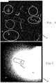
- FIG. 4 shows a measurement diagram of an obstacle map 4 according to an exemplary embodiment, which according to a threshold value application of the prior art based on the environment map according to the measurement diagram of FIG Fig. 2 was determined.
- This obstacle map 4 shows height information which is assigned to individual cells recognized as being occupied by an obstacle. Black symbolizes cells for which no obstacle was recognized. Grayscale and white symbolize an obstacle and the height of the obstacle.
- the occupancy probability of a cell compared with the same threshold value, for example 0.6. As can be seen, this comparison effectively suppresses the noise in area E and the systematic errors in area C.
- the obstacles in areas A and B are also not correctly recognized or represented.
- Fig. 4 shows a measurement diagram of an obstacle map 5 according to an embodiment of the invention. It was made by using the threshold map 6 according to the diagram of FIG Fig. 5 generated.
- the threshold map 6 has as many cells as the environment map 1. Each cell of the environment map is assigned a threshold value by the threshold map 6.
- the highest threshold value (area 7), for example 0.95, is represented by white, the lowest (area 9), for example 0.3, by black. Shades of gray (area 8) symbolize values in between.
- the distribution of the threshold values depends on the previous trajectory of the vehicle.
- the sensor properties in SFM processes namely the difficult detection of obstacles at a greater distance and in front of the vehicle, are taken into account.
- the probabilities of occupancy of the cells of the environment map 1 are compared with threshold values.
- the threshold values for the individual cells of the environment map 1 are not uniform or constant, but, as explained, different depending on the location (for example row and column) of the cell.
- the obstacles are represented in the areas A and B, while the noise and the misrecognition in the areas E and C are suppressed.
- the obstacles in area D are also correctly identified.
- the obstacle map 5 thus reproduces the obstacles in the surrounding area better than in accordance with the prior art method result shown in obstacle map 4.
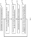
- the threshold map 6 and the obstacle map are generated using an iterative method that in Fig. 1 is explained.
- a start threshold map is provided. This can provide the same threshold value, for example 0.3, for all cells.
- This threshold map is adapted in step S2 according to the changed position (and orientation) of the vehicle. Typically, this will include a shift and rotation of the threshold map, provided that the threshold map is always to be arranged symmetrically and in a constant orientation to the vehicle.
- a threshold value pattern is applied to the threshold values of the individual cells of the threshold value map.
- the threshold value pattern can also be viewed as a threshold value map, the individual cells of which are assigned threshold value increments. These threshold value increments and threshold values of corresponding cells are added in order to arrive at the updated threshold value map.
- the threshold value increments are typically lower than the threshold values of the start threshold value map, for example 0.03; 0.05 or 0.07. If the addition would exceed a maximum threshold value, for example 0.95, the threshold value of the cell under consideration is set to the maximum threshold value.
- the distribution of the height of the threshold value increments in the cells of the threshold value pattern can follow a cone function or a Gaussian curve.
- the threshold values of the threshold value map reflect the previous trajectory of the vehicle.
- the current map of the surroundings is provided in step S4. As previously described, the current map of the surroundings was based on repeated entries of sensor readings (occupancy probabilities). The occupancy probabilities that are determined in a sensor measurement are added to occupancy probabilities previously recognized for the same section.
- the creation of the threshold map is iterative like the creation of the environment map. In the method it can be provided that the sensor measured values are incorporated into the environment map several times before a new obstacle map is created based on them. The threshold value increments of the threshold value pattern are adapted accordingly (i.e. higher).
- the obstacle map is determined in the last step S5. For this purpose, height information is only entered in the obstacle map for those cells that were recognized as occupied. Those cells are recognized as occupied whose occupancy probability is above the threshold value which is specified for the corresponding cell by the threshold value map.
- Steps S2 to S5 are repeated based on the newly created threshold map.
Landscapes
- Engineering & Computer Science (AREA)
- Physics & Mathematics (AREA)
- General Physics & Mathematics (AREA)
- Radar, Positioning & Navigation (AREA)
- Remote Sensing (AREA)
- Automation & Control Theory (AREA)
- Mathematical Physics (AREA)
- Transportation (AREA)
- Mechanical Engineering (AREA)
- Multimedia (AREA)
- Theoretical Computer Science (AREA)
- Acoustics & Sound (AREA)
- Computer Networks & Wireless Communication (AREA)
- Traffic Control Systems (AREA)
- Navigation (AREA)
Description
- Die Erfindung betrifft ein Verfahren zum Bereitstellen einer Hinderniskarte sowie ein entsprechend eingerichtetes elektronisches Steuergerät.
- Für viele zukünftige Fahrfunktionen und Fahrerassistenzsysteme eines Fahrzeugs, insbesondere das automatisierte Fahren, Einparkassistent, etc, ist die Erfassung des Umfeldes des Fahrzeugs unerlässlich. Insbesondere muss meist festgestellt werden, welche Abschnitte des Umfeldes nicht durch Hindernisse blockiert sind und damit uneingeschränkt befahrbar sind. Die Umfelderfassung wird dabei mit verschiedenen Sensorsystemen wie Kameraverbünde, Radar, Lidar und Ultraschallsensoren, ausgeführt. Zur Modellierung des Umfelds eines Fahrzeugs für verschiedene Kamera- bzw. generell sensorbasierte Fahrerassistenzsysteme (z.B. Einparkassistent), wird typischerweise eine Umfeldkarte, häufig auch als Occupancy Grid bezeichnet, als Modell verwendet.
- Eine Umfeldkarte umfasst Umfelddaten, die aus der Verarbeitung von Sensormessungen des Umfeldes resultieren und diese repräsentieren. Die Umfelddaten werden dabei meist nach Abschnitten des Umfeldes geordnet. Jedem Abschnitt werden diejenigen Umfelddaten zugeordnet, die aus Messungen in diesem Abschnitt resultieren. Die Umfelddaten können unterschiedliche Informationstypen je Zelle umfassen, beispielsweise die Belegungswahrscheinlichkeit der jeweiligen Zelle (also die Wahrscheinlichkeit, dass die Zelle von einem Hindernis belegt ist), die Höhe des Hindernisses etc.
- Manche Fahrerassistenzfunktionen benötigen zur Modellierung des Umfeldes nicht die abstrakte Belegungswahrscheinlichkeit als Information, sondern die Information, ob ein Abschnitt des Umfeldes durch ein Hindernis belegt ist, oder nicht. Ein Hindernis in einem Abschnitt bedeutet dabei, dass der Abschnitt des Umfeldes nicht oder nur unter Bedingungen mit dem Fahrzeug befahren werden kann.
- Zur Bereitstellung der Hindernisinformation, wird typischerweise eine Hinderniskarte erzeugt, die Zellen umfasst, die jeweils Abschnitten des Umfeldes des Fahrzeugs zugeordnet sind und denen jeweils die Information zugewiesen ist, ob der entsprechende Abschnitt des Umfeldes mit einem Hindernis belegt ist. Typischerweise entchende Abschnitt des Umfeldes mit einem Hindernis belegt ist. Typischerweise entsprechen die Zellen der Hinderniskarte den Zellen der Umfeldkarte und die zugeordneten Abschnitte sind gleich. Die Information, ob ein Abschnitt durch ein Hindernis belegt ist, wird durch den Vergleich der dem Abschnitt zugeordneten Belegungswahrscheinlichkeit der Umfeldkarte mit einem Schwellwert ermittelt. In manchen Ausprägungen kann darüber hinaus die für den Abschnitt festgestellte Hindernishöhe berücksichtigt werden.
- Im Fahrzeugbereich sind Sensorsysteme bekannt, die mittels eines "Structure from Motion" (SFM) genannten Verfahrens durch aufeinanderfolgende Kameraaufnahmen des Fahrzeugs aus verschiedenen Positionen heraus Hindernisse erkennen können. Allerdings ist diese Erkennung häufig fehlerbehaftet. Deshalb wird, um in einer Umfeldkarte aussagekräftige Belegungswahrscheinlichkeiten zu erzeugen, häufig die durch SFM erkannte Belegungswahrscheinlichkeit eines Abschnitts mit vorhergehend erkannten Belegungswahrscheinlichkeiten desselben Abschnitts verrechnet. Es findet also eine Akkumulation der erkannten Belegungswahrscheinlichkeiten einer Zelle der Umfeldkarte statt.
- Gleichzeitig ist im SFM Verfahren die korrekte Erkennung der Belegungswahrscheinlichkeit durch ein Hindernis in einem Abschnitt abhängig von der Entfernung zum Fahrzeug und dem Winkel zur Fahrzeuglängsachse. Beispielsweise werden Hindernisse frontal vor dem Fahrzeug häufiger nicht korrekt erkannt, als Hindernisse seitlich des Fahrzeugs. Selbst bei einer Akkumulation der zeitlich nacheinander bestimmten Belegungswahrscheinlichkeiten werden Hindernisse in der Umfeldkarte durch unterschiedliche Belegungswahrscheinlichkeiten repräsentiert.
- Bei der Erzeugung der Hinderniskarte basierend auf der Umfeldkarte durch Schwellwertbildung, entsteht so das Problem, dass Hindernisse, die aufgrund der Erkennungseigenschaften des SFM nur unzureichend durch Belegungswahrscheinlichkeiten repräsentiert werden, nicht in der Hinderniskarte verzeichnet werden.
- Dokument
DE 10 2011 081740 A1 betrifft eine Fahrumgebung-Erkennungseinrichtung, die in der Lage, eine Fahrumgebung eines Fahrzeugs präzise zu erkennen. Eine Belegungsgitterkarte, die eine Belegungswahrscheinlichkeit jedes Hindernisses für die Fahrt des eigenen Fahrzeugs für jede Zelle der Belegungsgitterkarte speichert, wird erzeugt, und die Belegungswahrscheinlichkeit für jede Zelle wird aktualisiert. - Der Erfindung liegt die Aufgabe zugrunde, das vorgehend erläuterte Problem zu lösen.
- Die Aufgabe wird durch das Verfahren, die Steuereinheit und das Fahrzeug gemäß den unabhängigen Ansprüchen gelöst. Vorteilhafte Weiterbildungen sind in den abhängigen Ansprüchen definiert.
- Ein Aspekt der Erfindung betrifft ein Verfahren zum Bereitstellen einer Hinderniskarte für Fahrfunktionen und Fahrerassistenzsysteme eines Fahrzeugs, wobei die Hinderniskarte Zellen umfasst, die jeweils Abschnitten des Umfeldes des Fahrzeugs zugeordnet sind und denen jeweils die Information zugewiesen ist, ob der entsprechende Abschnitt des Umfeldes mit einem Hindernis belegt ist; wobei das Verfahren umfasst: Bereitstellen einer Umfeldkarte, wobei die Umfeldkarte Zellen umfasst, die jeweils Abschnitten des Umfeldes des Fahrzeugs zugeordnet sind und denen jeweils eine Hinderniswahrscheinlichkeit zugewiesen ist, die die Wahrscheinlichkeit repräsentiert, dass der entsprechende Abschnitt des Umfeldes mit einem Hindernis belegt ist und die aus der Verarbeitung von Sensormessungen des Umfelds des Fahrzeugs resultiert; Bereitstellen einer Schwellwertvorschrift; wobei die Schwellwertvorschrift für Zellen der Umfeldkarte unterschiedliche Schwellwerte angibt; wobei die Schwellwertvorschrift abhängig von der Trajektorie, insbesondere einem Teil der bisherigen Trajektorie, des Fahrzeugs bestimmt wird; Bestimmen der Hinderniskarte basierend auf der Umfeldkarte und abhängig von der Schwellwertvorschrift. Die Schwellwertvorschrift kann eine explizite Angabe von Schwellwerten für jede Zelle der Umfeldkarte umfassen (auch Schwellwertkarte genannt) oder in einer geschlossenen Form dargestellt werden (Formel), aus der sich die Schwellwerte für einzelne Zellen der Umfeldkarte ermitteln lassen. Manchmal wird die Schwellwertkarte auch Explorationsgrid genannt. In die Bereitstellung der Umfeldkarte können Sensormesswerte mehrerer Sensorsysteme eingehen, beispielsweise Messungen aus Kamerasystemen und Ultraschallsystemen. Gleichzeitig kann die Schwellwertvorschrift die Erkennungseigenschaften (insbesondere Richtungs- und Entfernungsabhängigkeit) des Sensorsystems des Fahrzeugs berücksichtigten, mit dem die Belegungswahrscheinlichkeiten der Umfeldabschnitte bestimmt werden.
- Hierin wird also vorgeschlagen, keinen konstanten Schwellwert wie im Stand der Technik zu verwenden, sondern einen Schwellwert, der abschnittsbezogen (bzw. zellbezogen) variiert. Die Variation des Schwellwertes kann derart gewählt werden, dass die unterschiedlichen Erkennungseigenschaften von Hindernissen der Sensorik des Fahrzeugs berücksichtigt werden. Es wird für diejenigen Abschnitte ein hoher Schwellwert gewählt, für die die Erkennungseigenschaften des Sensors Hindernisse mit einer hohen Belegungswahrscheinlichkeit repräsentieren. Umgekehrt wird ein niedriger Schwellwert für jene Abschnitte gewählt, in denen Hindernisse durch geringere Belegungswahrscheinlichkeiten repräsentiert werden. Ebenfalls können die durch das Schwellwertmuster vorgegebenen Schwellwerte für die Abschnitte von der Fahrfunktion abhängen, die basierend auf der Hinderniskarte ausgeführt wird.
- Teil dieser Berücksichtigung ist die Trajektorie des Fahrzeugs. Sie bestimmt, für welche Abschnitte sich die Sensoreigenschaften auswirken, also in welchen Abschnitten des Umfeldes Hindernisse mit einer hohen Belegungswahrscheinlichkeit repräsentiert werden und in welchen Abschnitten Hindernisse mit einer niedrigen Belegungswahrscheinlichkeit repräsentiert werden. Typischerweise wird die Schwellwertvorschrift für Umfeldabschnitte in Fahrtrichtung vor dem Fahrzeug einen geringeren Schwellwert ansetzen, als für Abschnitte, an denen die bisherige Fahrtrajektorie seitlich vorbeiführte.
- Auf diese Weise werden auch weiter entfernt vor dem Fahrzeug in Fahrtrichtung liegende Hindernisse bei der Erstellung der Hinderniskarte korrekt erkannt. Gleichzeitig werden Hindernisse, die aufgrund der Sensoreigenschaften in höherem Maße erkannt werden (und in der Umfeldkarte eine entsprechend höhere Belegungswahrscheinlichkeit aufweisen) ebenfalls erkannt. Rauschen, das in jenen Bereichen gehäuft auftritt, in denen aufgrund der Sensoreigenschaften Hindernisse durch hohe Belegungswahrscheinlichkeiten repräsentiert sind, wird ebenfalls wirksam bei der Erstellung der Hinderniskarte unterdrückt.
- In einer vorteilhaften Implementierung wird zur Bestimmung der Schwellwertvorschrift ein Schwellwertmuster wiederholt berücksichtigt; wobei das Schwellwertmuster für unterschiedliche Zellen aus einer Gruppe von Zellen verschiedene Schwellwertinkremente angibt. Die Gruppe von Zellen kann von der Anzahl her kleiner sein, als die Anzahl der Zellen der Umfeldkarte. Das Schwellwertmuster kann eine Schwellwertmusterkarte sein, die für einzelne Zellen Schwellwertinkremente vorgibt. Vorteilhafterweise folgenden die Schwellwerte, die das Muster angibt, einer Gauß-Funktion oder einer linearen Funktion. Das Schwellwertmuster gibt dabei die Eigenschaften der Hinderniserkennung des Sensorsystems bei einer einzelnen Messung wieder (wobei eine einzelne Messung hier als Datengrundlage verstanden wird, auf der die Aktualisierung der Umfeldkarte ausgeführt wird und durchaus mehrere Rohmessungen vereinen kann). Das Schwellwertmuster kann auch die Eigenschaften verschiedener Sensorsysteme berücksichtigen, beispielsweise SFM Kamerasysteme und Ultraschall. Hieraus können komplexe Schwellwertmuster entstehen.
- Das Schwellwertmuster wird typischerweise unverändert wiederholt angewendet bzw. berücksichtigt. Ausgangspunkt kann dabei eine vorgegebene Start-Schwellwertvorschrift sein. Zu dieser wird wiederholt das Schwellwertmuster addiert, und zwar abhängig von der Trajektorie des Fahrzeugs. Der Schwellwert einzelner Zellen der Umfeldkarte kann dabei auf einen Maximalwert, beispielsweise 0,9, begrenzt werden.
- Die inkrementelle Weiterentwicklung der Schwellwertvorschrift birgt den Vorteil, dass für jede aufeinanderfolgende Bestimmung der Hinderniskarte, auf der bisherigen Schwellwertvorschrift aufgebaut werden kann. Zu der zuletzt bestimmten Schwellwertvorschrift wird lediglich das Schwellwertmuster entsprechend der aktuellen Fahrzeugposition addiert. Die neue Fahrzeugposition kann auch durch eine Verschiebung der Umfeldkarte oder dessen Inhalts reflektiert werden.
- Sofern die Aktualisierung der Umfeldkarte (aufgrund neuer Sensormessungen) in regelmäßigen Zeit- oder Wegabschnitten stattfindet, kann die Akkumulation (bzw. die Bereitstellung des aktualisierten Schwellwertmusters) in denselben Zeitabschnitten oder, sofern die Einarbeitung von dem Zurücklegen einer Fahrstrecke abhängig ist, nach vorbestimmten Wegstrecken der Fahrtrajektorie durchgeführt werden.
- Zwischen der Bestimmung zweier Hinderniskarten können eine oder mehrere Berücksichtigungen bzw. Akkumulationen (Additionen) des Schwellwertmusters vorgenommen werden, um die dann anzuwendende Schwellwertvorschrift zu bestimmen. Dies kann von der Anzahl der Einarbeitung neuer Sensormessungen (also deren neu erkannten Belegungswahrscheinlichkeiten der Abschnitte des Umfelds) abhängen. Ebenso kann das Schwellwertmuster, insbesondere die Höhe der Schwellwertinkremente, von der Anzahl der Aktualisierungen der Umfeldkarte durch jeweils neue Sensormessungen des Umfeldes abhängen.
- Das Schwellwertmuster kann abhängig von der Position und/oder Ausrichtung des Fahrzeugs in der Umfeldkarte bei der Bestimmung der Schwellwertvorschrift berücksichtigt werden. Dies bedeutet also, dass bei der Anwendung des Schwellwertmusters auf die Start-Schwellwertkarte die bei den einzelnen Zellen der Schwellwertkarte zu addierenden Schwellwertinkremente (aufgrund der Vorgaben des Schwellwertmusters) anhand der Fahrzeugposition bestimmt werden. Mit anderen Worten: Das Schwellwertmuster weist einen Referenzpunkt, beispielsweise den Symmetriepunkt des Musters, (und ggf. eine Referenzrichtung) auf, der an der Fahrzeugposition (und ggf. Fahrzeugausrichtung) orientiert wird.
- In vorteilhaften Implementierungen ist Zellen der Umfeldkarte jeweils derselbe Abschnitt des Umfeldes zugeordnet wie Zellen der Hinderniskarte; wobei die Information für eine Zelle der Hinderniskarte durch einen Vergleich der Belegungswahrscheinlichkeit der entsprechenden Zelle der Umfeldkarte mit einem für die entsprechende Zelle der Umfeldkarte angegebenen Schwellwert gemäß der Schwellwertvorschrift gewonnen wird. Die Hinderniskarte und die Umfeldkarte entsprechen sich somit vom Zellaufbau her.
- Ein anderer Aspekt der Erfindung betrifft ein elektronisches Steuergerät für Fahrzeuge, wobei das Steuergerät zur Ausführung eines der oben beschriebenen Verfahren eingerichtet ist. Das Steuergerät kann ein Mikrocontroller, eine CPU ein ASIC oder RISC sein. Ein weiterer Aspekt der Erfindung betrifft ein Fahrzeug, insbesondere einen PKW, umfassend das Steuergerät.
-
-
Fig. 2 zeigt ein Messdiagramm einer Umfeldkarte gemäß einem Ausführungsbeispiel. -
Fig. 3 zeigt ein Messdiagramm einer gemäß dem Stand der Technik erzeugten Hinderniskarte. -
Fig. 4 zeigt ein Messdiagramm einer Hinderniskarte gemäß einem Ausführungsbeispiel der Erfindung. -
Fig. 5 zeigt beispielhaft ein Diagramm einer erfindungsgemäßen Schwellwertkarte wie sie zur Bestimmung des Messdiagramms inFig. 4 verwendet wurde. -
Fig. 1 zeigt ein Ablaufdiagramm eines Verfahrens gemäß einem Ausführungsbeispiel. - Gleiche Bezugszeichen beziehen sich auf sich entsprechende Elemente über die Diagramme hinweg.
-
Fig. 2 zeigt das Messdiagramm einer Umfeldkarte 1 gemäß einem Ausführungsbeispiel. Die Umfeldkarte umfasst 256x256 Zellen, deren zugeordnete Belegungswahrscheinlichkeit anhand von Grauabstufungen dargestellt ist. Weiß bedeutet, dass der entsprechende Abschnitt des Umfeldes als unbelegt erfasst wurde, die Belegungswahrscheinlichkeit also mit 0% festgestellt wurde. Grau bedeutet, dass keine Aussage über die Belegung möglich ist, also eine Belegungswahrscheinlichkeit von 50% vorliegt. Schwarz bedeutet, dass eine Belegung vorliegt, der Zelle also eine Belegungswahrscheinlichkeit von 100% zugewiesen ist. Wie im Beispiel des Messdiagramms derFig. 2 ersichtlich, ist der Mehrzahl der Zellen eine unbekannte Belegungswahrscheinlichkeit zugewiesen. - Die Messungen wurden vom Fahrzeug 2 mithilfe von Kameras des Fahrzeugs und eines SFM Verfahrens durchgeführt. Von den dabei ermittelten Belegungswahrscheinlichkeiten und Höheninformationen für die Abschnitte des Umfeldes sind im Messdiagramm der
Fig. 2 nur die Belegungsinformationen dargestellt. Im Fahrzeug 2 wird die Hinterachse durch den Querbalken symbolisiert. Die bisherige Trajektorie des vorwärts fahrenden Fahrzeugs 2 ist durch die weiße Spur 3 ersichtlich. In Messdiagramm derFig. 2 ist das Resultat der Belegungserkennung des Umfeldes nach Durchfahren der Spur 3 dargestellt. - In den Bereichen A und B vor dem Fahrzeug befinden sich jeweils Hindernisse. Aufgrund der Erkennungseigenschaften des verwendeten SFM Verfahrens wird diesen Hindernissen allerdings eine geringe Belegungswahrscheinlichkeit zugewiesen. Aufgrund der Entfernung zum Fahrzeug und der Anordnung in Fahrtrichtung vor dem Fahrzeug werden im SFM Verfahren selten Hindernisse gemessen.
- Ebenfalls in Messdiagramm der
Fig. 2 markiert ist Rauschen im Bereich E. - Im Bereich C werden Zellen fälschlicherweise Belegungswahrscheinlichkeiten größer 50% zugewiesen, obwohl sich dort kein Hindernis befindet. Dies resultiert aus systematischen Messfehlern, die wiederholt auftreten.
- Im Bereich D befinden sich Hindernisse, die bei Messungen häufig als solche erkannt wurden. Folglich werden diese auch mit hohen Belegungswahrscheinlichkeiten im der Umfeldkarte repräsentiert.
-
Fig. 3 zeigt ein Messdiagramm einer Hinderniskarte 4 gemäß einem Ausführungsbeispiel, die gemäß einer Schwellwertanwendung des Standes der Technik basierend auf der Umfeldkarte gemäß dem Messdiagramm derFig. 2 bestimmt wurde. Diese Hinderniskarte 4 zeigt Höheninformationen, die einzelnen als mit einem Hindernis belegt erkannten Zellen zugeordnet sind. Schwarz symbolisiert Zellen, für die kein Hindernis erkannt wurde. Graustufen und Weiß symbolisieren ein Hindernis und die Höhe des Hindernisses. Zur Entscheidung, ob eine Zelle durch ein Hindernis belegt wird, wurde die Belegungswahrscheinlichkeit einer Zelle (im Messdiagramm derFig. 2 dargestellt) jeweils mit demselben Schwellwert verglichen, beispielsweise 0,6. Wie ersichtlich ist, werden durch diesen Vergleich zwar effektiv das Rauschen im Bereich E und die systematischen Fehler in Bereich C unterdrückt. Allerdings werden auch die Hindernisse in den Bereichen A und B nicht korrekt erkannt bzw. repräsentiert. - Die Verwendung eines niedrigeren Schwellwertes als im Messdiagramm der
Fig. 3 würde zwar zur Repräsentation der Hindernisse in den Bereichen A und B führen, aber auch fälschlicherweise Hindernisse in den Bereichen C und E anzeigen. Die Verwendung eines konstanten Schwellwertes wie im Stand der Technik bekannt, liefert im vorliegenden Beispiel der Sensormessungen mittels SFM also keine zufriedenstellende Erkennung von Hindernissen bei gleichzeitiger Rauschunterdrückung. -
Fig. 4 zeigt ein Messdiagramm einer Hinderniskarte 5 gemäß einem Ausführungsbeispiel der Erfindung. Sie wurde durch Anwendung der Schwellwertkarte 6 gemäß dem Diagramm derFig. 5 erzeugt. Die Schwellwertkarte 6 weist ebensoviele Zellen auf, wie die Umfeldkarte 1. Jeder Zelle der Umfeldkarte ist durch die Schwellwertkarte 6 ein Schwellwert zugeordnet. Im Diagramm derFig. 5 wird der höchste Schwellwert (Bereich 7), beispielsweise 0,95, durch Weiß dargestellt, der niedrigste (Bereich 9), beispielsweise 0,3, durch Schwarz. Graustufen (Bereich 8) symbolisieren Werte dazwischen. Wie ersichtlich ist, hängt die Verteilung der Schwellwerte von der bisherigen Trajektorie des Fahrzeugs ab. Gleichzeitig werden die Sensoreigenschaften bei SFM Verfahren, nämlich die erschwerte Erfassung von Hindernissen in größerer Entfernung und frontal vor dem Fahrzeug, berücksichtigt. - Wie zur Erzeugung des Messdiagramms der
Fig. 3 werden die Belegungswahrscheinlichkeiten der Zellen der Umfeldkarte 1 mit Schwellwerten verglichen. Allerdings sind gemäß der Erfindung die Schwellwerte für die einzelnen Zellen der Umfeldkarte 1 nicht einheitlich bzw. konstant, sondern, wie erläutert, je nach Lage (beispielsweise Zeile und Spalte) der Zelle unterschiedlich. Im Ergebnis werden die Hindernisse in den Bereichen A und B repräsentiert, während das Rauschen und die Fehlerkennung in den Bereichen E und C unterdrückt werden. Weiterhin korrekt erkannt werden die Hindernisse in Bereich D. Insgesamt gibt die Hinderniskarte 5 somit die Hindernisse im Umfeld besser wieder als gemäß dem in Hinderniskarte 4 dargestellten Verfahrensresultats des Standes der Technik. - Die Schwellwertkarte 6 und die Hinderniskarte wird mithilfe eines iterativen Verfahrens erzeugt, dass in
Fig. 1 erläutert ist. In Schritt S1 wird eine Start-Schwellwertkarte bereitgestellt. Diese kann für alle Zellen denselben Schwellwert, beispielsweise 0,3 vorsehen. Diese die Schwellwertkarte wird im Schritt S2 gemäß der veränderten Position (und Ausrichtung) des Fahrzeugs angepasst. Typischerweise wird dies eine Verschiebung und Drehung der Schwellwertkarte umfassen, sofern die Schwellwertkarte stets symmetrisch und in gleichbleibender Ausrichtung zum Fahrzeug angeordnet sein soll. - Auf die Schwellwerte der einzelnen Zellen der Schwellwertkarte wird im Schritt S3 ein Schwellwertmuster angewandt. Das Schwellwertmuster kann ebenfalls als Schwellwertkarte betrachtet werden, deren einzelnen Zellen Schwellwertinkremente zugewiesen sind. Diese Schwellwertinkremente und Schwellwerte sich entsprechender Zellen werden addiert, um zur aktualisierten Schwellwertkarte zu gelangen. Die Schwellwertinkremente sind typischerweise geringer als die Schwellwerte der Start-Schwellwertkarte, beispielsweise 0,03; 0,05 oder 0,07. Sofern die Addition einen Maximalschwellwert überschreiten würde, beispielsweise 0,95, wird der Schwellwert der betrachteten Zelle auf den Maximalschwellwert gesetzt. Die Verteilung der Höhe der Schwellwertinkremente in den Zellen des Schwellwertmusters kann einer Kegelfunktion oder Gauß-Kurve folgen.
- Es ist direkt verständlich, dass durch die wiederholte Anwendung des Schwellwertmusters auf die jeweils zuvor entstandene Schwellwertkarte, die Schwellwerte der Schwellwertkarte die bisherige Trajektorie des Fahrzeugs widerspiegeln.
- Im Schritt S4 wird die aktuelle Umfeldkarte bereitgestellt. Wie zuvor beschrieben basierte die aktuelle Umfeldkarte auf wiederholten Eintragungen von Sensormesswerten (Belegungswahrscheinlichkeiten). Dabei werden die Belegungswahrscheinlichkeiten, die in einer Sensormessung festgestellt werden, auf zuvor für denselben Abschnitt erkannte Belegungswahrscheinlichkeiten addiert. Die Erstellung der Schwellwertkarte ist somit wie die Erstellung der Umfeldkarte iterativ. Im Verfahren kann vorgesehen sein, dass die Sensormesswerte mehrmals in die Umfeldkarte eingearbeitet werden, bevor darauf aufbauend eine neue Hinderniskarte erstellt wird. Die Schwellwerteinkremente des Schwellwertmusters sind entsprechend angepasst (also höher).
- Im letzten Schritt S5 wird die Hinderniskarte bestimmt. Dazu werden in die Hinderniskarte nur für diejenigen Zellen Höheninformationen eingetragen, die als belegt erkannt wurden. Als belegt werden diejenigen Zellen erkannt, deren Belegungswahrscheinlichkeit über dem Schwellwert liegt, der für die entsprechende Zelle durch die Schwellwertkarte vorgegeben wird.
- Die Schritte S2 bis S5 werden basierend auf der neu erstellten Schwellwertkarte wiederholt.
Claims (9)
- Verfahren zum Bereitstellen einer Hinderniskarte für Fahrfunktionen und Fahrerassistenzsysteme eines Fahrzeugs, wobei die Hinderniskarte Zellen umfasst, die jeweils Abschnitten des Umfeldes des Fahrzeugs zugeordnet sind und denen jeweils die Information zugewiesen ist, ob der entsprechende Abschnitt des Umfeldes mit einem Hindernis belegt ist; wobei das Verfahren umfasst:Bereitstellen einer Umfeldkarte, wobei die Umfeldkarte Zellen umfasst, die jeweils Abschnitten des Umfeldes des Fahrzeugs zugeordnet sind und denen jeweils eine Hinderniswahrscheinlichkeit zugewiesen ist, die die Wahrscheinlichkeit repräsentiert, dass der entsprechende Abschnitt des Umfeldes mit einem Hindernis belegt ist und die aus der Verarbeitung von Sensormessungen des Umfelds des Fahrzeugs resultiert;Bereitstellen einer Schwellwertvorschrift;wobei die Schwellwertvorschrift für Zellen der Umfeldkarte unterschiedliche Schwellwerte angibt;wobei die Schwellwertvorschrift abhängig von der Trajektorie des Fahrzeugs bestimmt wird;Bestimmen der Hinderniskarte basierend auf der Umfeldkarte und abhängig von der Schwellwertvorschrift.
- Verfahren nach Anspruch 1, wobei zur Bestimmung der Schwellwertvorschrift ein Schwellwertmuster wiederholt berücksichtigt wird; wobei das Schwellwertmuster für unterschiedliche Zellen aus einer Gruppe von Zellen verschiedene Schwellwertinkremente angibt.
- Verfahren nach Anspruch 2, wobei die Schwellwertvorschrift eine Schwellwertkarte umfasst, die für die Zellen der Umfeldkarte jeweils ein Schwellwertinkrement angibt.
- Verfahren nach einem der Ansprüche 2 oder 3, wobei beim Berücksichtigen des Schwellwertmusters die Schwellwertinkremente des Schwellwertmusters zu den Schwellwerten einer vorhergehend bestimmten Schwellwertvorschrift, insbesondere Schwellwertkarte, addiert werden.
- Verfahren nach einem der Ansprüche 2 bis 4, wobei das Schwellwertmuster abhängig von der Position und/oder Ausrichtung des Fahrzeugs in der Umfeldkarte bei der Bestimmung der Schwellwertvorschrift berücksichtigt wird.
- Verfahren nach einem der vorhergehenden Ansprüche, wobei die Schwellwertvorschrift ferner zeitabhängig und/oder abhängig von der Einarbeitung von Sensormessungen des Umfeldes in die Umfeldkarte ist.
- Verfahren nach einem der vorhergehenden Ansprüche, wobei Zellen der Umfeldkarte jeweils derselbe Abschnitt des Umfeldes zugeordnet ist wie Zellen der Hinderniskarte; wobei die Information für eine Zelle der Hinderniskarte durch einen Vergleich der Belegungswahrscheinlichkeit der entsprechenden Zelle der Umfeldkarte mit einem für die entsprechende Zelle der Umfeldkarte angegebenen Schwellwert gemäß der Schwellwertvorschrift gewonnen wird.
- Elektronisches Steuergerät für Fahrzeuge, wobei das Steuergerät zur Ausführung eines Verfahrens nach einem der vorhergehenden Ansprüche eingerichtet ist.
- Fahrzeug, umfassend ein Steuergerät nach Anspruch 8.
Applications Claiming Priority (2)
| Application Number | Priority Date | Filing Date | Title |
|---|---|---|---|
| DE102015205244.3A DE102015205244B3 (de) | 2015-03-24 | 2015-03-24 | Verfahren zum Bereitstellen von Hinderniskarten für Fahrzeuge |
| PCT/EP2016/055212 WO2016150728A1 (de) | 2015-03-24 | 2016-03-11 | Verfahren zum bereitstellen von hinderniskarten für fahrzeuge |
Publications (2)
| Publication Number | Publication Date |
|---|---|
| EP3204792A1 EP3204792A1 (de) | 2017-08-16 |
| EP3204792B1 true EP3204792B1 (de) | 2020-12-30 |
Family
ID=54549099
Family Applications (1)
| Application Number | Title | Priority Date | Filing Date |
|---|---|---|---|
| EP16711551.8A Active EP3204792B1 (de) | 2015-03-24 | 2016-03-11 | Verfahren zum bereitstellen von hinderniskarten für fahrzeuge |
Country Status (5)
| Country | Link |
|---|---|
| US (1) | US10460603B2 (de) |
| EP (1) | EP3204792B1 (de) |
| CN (1) | CN107000753B (de) |
| DE (1) | DE102015205244B3 (de) |
| WO (1) | WO2016150728A1 (de) |
Families Citing this family (14)
| Publication number | Priority date | Publication date | Assignee | Title |
|---|---|---|---|---|
| US10635913B2 (en) * | 2016-10-17 | 2020-04-28 | Mediatek Inc. | Path planning method and related navigation device |
| DE102016123391A1 (de) * | 2016-12-02 | 2018-06-07 | Continental Engineering Services Gmbh | Verfahren zur Unterstützung eines Einparkvorganges sowie Parkassistenzvorrichtung |
| US10195992B2 (en) | 2017-04-03 | 2019-02-05 | Ford Global Technologies, Llc | Obstacle detection systems and methods |
| EP3514648B1 (de) * | 2018-01-22 | 2023-09-06 | Continental Autonomous Mobility Germany GmbH | Verfahren und vorrichtung zur erkennung einer grenze in einer umgebung eines objektes |
| KR102704006B1 (ko) * | 2019-02-14 | 2024-09-05 | 한화에어로스페이스 주식회사 | 장애물 지도 생성 방법 및 그 장치 |
| CN109849936A (zh) * | 2019-03-07 | 2019-06-07 | 无锡众创未来科技应用有限公司 | 一种车辆周边局部障碍物地图的生成方法 |
| CN110045376B (zh) * | 2019-04-28 | 2021-06-01 | 森思泰克河北科技有限公司 | 可行驶区域获取方法、计算机可读存储介质及终端设备 |
| CN111942374A (zh) * | 2020-08-14 | 2020-11-17 | 中国第一汽车股份有限公司 | 一种障碍物地图生成方法、装置、车辆及存储介质 |
| DE102020215255A1 (de) * | 2020-12-03 | 2022-06-09 | Continental Automotive Gmbh | Verfahren zur Höhenklassifikation von Objekten mittels Ultraschallsensorik |
| US11462021B2 (en) * | 2021-01-13 | 2022-10-04 | GM Global Technology Operations LLC | Obstacle detection and notification for motorcycles |
| CN112644480B (zh) * | 2021-01-18 | 2022-12-13 | 广州小鹏自动驾驶科技有限公司 | 一种障碍物检测方法、检测系统、计算机设备和存储介质 |
| GB202108228D0 (en) * | 2021-06-09 | 2021-07-21 | Agco Int Gmbh | Residue spread mapping |
| US12325450B2 (en) * | 2021-08-23 | 2025-06-10 | Ford Global Technologies, Llc | Systems and methods for generating multilevel occupancy and occlusion grids for controlling navigation of vehicles |
| CN114253273B (zh) * | 2021-12-23 | 2024-04-12 | 南京世泽科技有限公司 | 一种基于多线激光雷达的避障方法 |
Family Cites Families (17)
| Publication number | Priority date | Publication date | Assignee | Title |
|---|---|---|---|---|
| DE10230483A1 (de) * | 2002-07-06 | 2004-01-15 | Robert Bosch Gmbh | Verfahren zur Ansteuerung eines zweistufigen Gurtstraffers |
| DE10244148A1 (de) | 2002-09-23 | 2004-04-08 | Daimlerchrysler Ag | Verfahren und Vorrichtung zur videobasierten Beobachtung und Vermessung der seitlichen Umgebung eines Fahrzeugs |
| JP4412337B2 (ja) * | 2007-03-08 | 2010-02-10 | トヨタ自動車株式会社 | 周囲環境推定装置及び周囲環境推定システム |
| JP4623057B2 (ja) * | 2007-06-05 | 2011-02-02 | トヨタ自動車株式会社 | 自車両の移動領域取得装置 |
| US8244458B1 (en) * | 2008-06-23 | 2012-08-14 | The United States Of America As Represented By The Secretary Of The Navy | Host-centric method for automobile collision avoidance decisions |
| EP2583062B1 (de) * | 2010-06-15 | 2017-08-09 | TomTom Global Content B.V. | Standort- und zeitplanerfassung sowie reisezeitschätzungen für barrierenkreuzungen auf einer digitalen karte |
| JP5206752B2 (ja) | 2010-08-30 | 2013-06-12 | 株式会社デンソー | 走行環境認識装置 |
| US8571722B2 (en) * | 2010-10-22 | 2013-10-29 | Toyota Motor Engineering & Manufacturing North America, Inc. | Method for safely parking vehicle near obstacles |
| DE102011113016A1 (de) * | 2011-09-09 | 2012-03-29 | Daimler Ag | Verfahren zur Umgebungsrepräsentation eines Fahrzeugs |
| DE102011116613A1 (de) * | 2011-10-20 | 2013-04-25 | Atlas Elektronik Gmbh | Unbemanntes Unterwasserfahrzeug und Verfahren zum Lokalisieren und Untersuchen eines am Gewässergrund eines Gewässers angeordenten Objekts sowie System mit dem unbemannten Unterwasserfahrzeug |
| WO2013060323A1 (de) * | 2011-10-28 | 2013-05-02 | Conti Temic Microelectronic Gmbh | Gitterbasiertes umfeldmodell für ein fahrzeug |
| JP6015227B2 (ja) * | 2012-08-10 | 2016-10-26 | アイシン・エィ・ダブリュ株式会社 | 交差点案内システム、方法およびプログラム |
| DE102013207905A1 (de) * | 2013-04-30 | 2014-10-30 | Bayerische Motoren Werke Aktiengesellschaft | Verfahren zum effizienten Bereitstellen von Belegungsinformationen über Abschnitte des Umfeldes eines Fahrzeugs |
| JP2015155878A (ja) * | 2014-02-21 | 2015-08-27 | 株式会社デンソー | 車両用障害物検出装置 |
| US9766336B2 (en) * | 2015-03-16 | 2017-09-19 | Here Global B.V. | Vehicle obstruction detection |
| US9505413B2 (en) * | 2015-03-20 | 2016-11-29 | Harman International Industries, Incorporated | Systems and methods for prioritized driver alerts |
| US9868443B2 (en) * | 2015-04-27 | 2018-01-16 | GM Global Technology Operations LLC | Reactive path planning for autonomous driving |
-
2015
- 2015-03-24 DE DE102015205244.3A patent/DE102015205244B3/de active Active
-
2016
- 2016-03-11 EP EP16711551.8A patent/EP3204792B1/de active Active
- 2016-03-11 WO PCT/EP2016/055212 patent/WO2016150728A1/de not_active Ceased
- 2016-03-11 CN CN201680004234.0A patent/CN107000753B/zh active Active
-
2017
- 2017-09-22 US US15/713,115 patent/US10460603B2/en active Active
Non-Patent Citations (1)
| Title |
|---|
| None * |
Also Published As
| Publication number | Publication date |
|---|---|
| CN107000753A (zh) | 2017-08-01 |
| DE102015205244B3 (de) | 2015-12-10 |
| EP3204792A1 (de) | 2017-08-16 |
| WO2016150728A1 (de) | 2016-09-29 |
| CN107000753B (zh) | 2019-08-20 |
| US10460603B2 (en) | 2019-10-29 |
| US20180012494A1 (en) | 2018-01-11 |
Similar Documents
| Publication | Publication Date | Title |
|---|---|---|
| EP3204792B1 (de) | Verfahren zum bereitstellen von hinderniskarten für fahrzeuge | |
| DE102016107938B4 (de) | Vorausschauendes fahrzeuggeschwindigkeitsregelungssystem und verfahren zur vorausschauenden geschwindigkeitsregelung | |
| DE102008001409A1 (de) | Verfahren zur Bestimmung von freien Bereichen in der, insbesondere für die Fahrzeugführung relevanten Umgebung eines Kraftfahrzeugs | |
| WO2020229002A1 (de) | Verfahren und vorrichtung zur multi-sensor-datenfusion für automatisierte und autonome fahrzeuge | |
| DE102016212326A1 (de) | Verfahren zur Verarbeitung von Sensordaten für eine Position und/oder Orientierung eines Fahrzeugs | |
| WO2019072674A1 (de) | Verfahren und vorrichtung zum erzeugen eines inversen sensormodells und verfahren zum erkennen von hindernissen | |
| WO2015139864A1 (de) | Verfahren und vorrichtung zum betreiben eines fahrzeugs | |
| DE102019133708A1 (de) | Verfahren und vorrichtung zum erfassen von statischen und dynamischen informationen auf spurniveau | |
| EP2888604A1 (de) | Verfahren zur bestimmung eines fahrspurverlaufs für ein fahrzeug | |
| DE102014204309A1 (de) | Vorrichtung und Verfahren zum Betreiben eines Fahrzeugs | |
| AT518940B1 (de) | Verfahren und Vorrichtung zum Messen eines Abstands zwischen einem ersten Fahrzeug und einem zweiten, dem ersten Fahrzeug unmittelbar vorausfahrenden, Fahrzeug | |
| DE102021127078A1 (de) | Verfahren zum Plausibilisieren einer auf Basis von Schwarmdaten erzeugten Trajektorie für ein zumindest teilweise assistiert betriebenes Kraftfahrzeug, Computerprogrammprodukt sowie Assistenzsystem | |
| DE102019101040A1 (de) | Verfahren zum Trainieren einer Trajektorie für ein Fahrzeug, sowie elektronisches Fahrzeugführungssystem | |
| DE102013203908A1 (de) | Schätzung der zukünftigen Geschwindigkeit eines Fahrzeugs | |
| DE102018124979A1 (de) | Fahrerassistenzsystem zur Bestimmung einer Entfernung zwischen zwei Fahrzeugen mit einer Kamera | |
| DE102018204451A1 (de) | Verfahren und Vorrichtung zur Autokalibrierung eines Fahrzeugkamerasystems | |
| DE102008026876A1 (de) | Stereokamerasystem und Verfahren zum Ermitteln mindestens eines Kalibrierfehlers eines Stereokamerasystems | |
| DE102019132150A1 (de) | Verfahren zum automatischen Kalibrieren eines Umfeldsensors, insbesondere eines Lidar-Sensors, eines Fahrzeugs auf Grundlage von Belegungskarten sowie Recheneinrichtung | |
| DE102011076795A1 (de) | Verfahren zum Bestimmen einer Nickbewegung einer in einem Fahrzeug verbauten Kamera und Verfahren zur Steuerung einer Lichtaussendung zumindest eines Frontscheinwerfers eines Fahrzeugs | |
| DE102019102922A1 (de) | Verfahren und Vorrichtung zur Multi-Sensor-Datenfusion für automatisierte und autonome Fahrzeuge | |
| DE102017201796A1 (de) | Steuervorrichtung zum Ermitteln einer Eigenbewegung eines Kraftfahrzeugs sowie Kraftfahrzeug und Verfahren zum Bereitstellen der Steuervorrichtung | |
| DE102009024131A1 (de) | Verfahren zur Ermittelung einer Fahrspur und Fahrerassistenzsystem für ein Fahrzeug mit Mitteln zur Ermittelung einer Fahrspur | |
| WO2013164182A2 (de) | Verfahren und vorrichtung zur bestimmung eines umfelds | |
| DE102013013253A1 (de) | Verfahren zum Warnen des Fahrers eines Kraftfahrzeugs abhängig von einer ermittelten Zeit bis zur Kollision, Kamerasystem und Kraftfahrzeug | |
| DE102015104940A1 (de) | Verfahren zum Bereitstellen von Höheninformationen eines Objekts in einem Umgebungsbereich eines Kraftfahrzeugs an einer Kommunikationsschnittstelle, Sensoreinrichtung, Verarbeitungseinrichtung und Kraftfahrzeug |
Legal Events
| Date | Code | Title | Description |
|---|---|---|---|
| STAA | Information on the status of an ep patent application or granted ep patent |
Free format text: STATUS: THE INTERNATIONAL PUBLICATION HAS BEEN MADE |
|
| PUAI | Public reference made under article 153(3) epc to a published international application that has entered the european phase |
Free format text: ORIGINAL CODE: 0009012 |
|
| STAA | Information on the status of an ep patent application or granted ep patent |
Free format text: STATUS: REQUEST FOR EXAMINATION WAS MADE |
|
| 17P | Request for examination filed |
Effective date: 20170509 |
|
| AK | Designated contracting states |
Kind code of ref document: A1 Designated state(s): AL AT BE BG CH CY CZ DE DK EE ES FI FR GB GR HR HU IE IS IT LI LT LU LV MC MK MT NL NO PL PT RO RS SE SI SK SM TR |
|
| AX | Request for extension of the european patent |
Extension state: BA ME |
|
| DAV | Request for validation of the european patent (deleted) | ||
| DAX | Request for extension of the european patent (deleted) | ||
| GRAP | Despatch of communication of intention to grant a patent |
Free format text: ORIGINAL CODE: EPIDOSNIGR1 |
|
| STAA | Information on the status of an ep patent application or granted ep patent |
Free format text: STATUS: GRANT OF PATENT IS INTENDED |
|
| RIC1 | Information provided on ipc code assigned before grant |
Ipc: G06K 9/00 20060101ALI20200814BHEP Ipc: G01S 15/931 20200101ALI20200814BHEP Ipc: G08G 1/16 20060101ALI20200814BHEP Ipc: B60W 30/08 20120101ALI20200814BHEP Ipc: G01S 15/93 20200101AFI20200814BHEP Ipc: B60W 40/04 20060101ALI20200814BHEP Ipc: G06K 9/62 20060101ALI20200814BHEP |
|
| INTG | Intention to grant announced |
Effective date: 20200916 |
|
| RIN1 | Information on inventor provided before grant (corrected) |
Inventor name: WALESSA, MARC Inventor name: KORMANN, OLIVER |
|
| GRAS | Grant fee paid |
Free format text: ORIGINAL CODE: EPIDOSNIGR3 |
|
| GRAA | (expected) grant |
Free format text: ORIGINAL CODE: 0009210 |
|
| STAA | Information on the status of an ep patent application or granted ep patent |
Free format text: STATUS: THE PATENT HAS BEEN GRANTED |
|
| AK | Designated contracting states |
Kind code of ref document: B1 Designated state(s): AL AT BE BG CH CY CZ DE DK EE ES FI FR GB GR HR HU IE IS IT LI LT LU LV MC MK MT NL NO PL PT RO RS SE SI SK SM TR |
|
| REG | Reference to a national code |
Ref country code: GB Ref legal event code: FG4D Free format text: NOT ENGLISH |
|
| REG | Reference to a national code |
Ref country code: AT Ref legal event code: REF Ref document number: 1350466 Country of ref document: AT Kind code of ref document: T Effective date: 20210115 |
|
| REG | Reference to a national code |
Ref country code: DE Ref legal event code: R096 Ref document number: 502016012074 Country of ref document: DE |
|
| REG | Reference to a national code |
Ref country code: IE Ref legal event code: FG4D Free format text: LANGUAGE OF EP DOCUMENT: GERMAN |
|
| PG25 | Lapsed in a contracting state [announced via postgrant information from national office to epo] |
Ref country code: NO Free format text: LAPSE BECAUSE OF FAILURE TO SUBMIT A TRANSLATION OF THE DESCRIPTION OR TO PAY THE FEE WITHIN THE PRESCRIBED TIME-LIMIT Effective date: 20210330 Ref country code: RS Free format text: LAPSE BECAUSE OF FAILURE TO SUBMIT A TRANSLATION OF THE DESCRIPTION OR TO PAY THE FEE WITHIN THE PRESCRIBED TIME-LIMIT Effective date: 20201230 Ref country code: GR Free format text: LAPSE BECAUSE OF FAILURE TO SUBMIT A TRANSLATION OF THE DESCRIPTION OR TO PAY THE FEE WITHIN THE PRESCRIBED TIME-LIMIT Effective date: 20210331 Ref country code: FI Free format text: LAPSE BECAUSE OF FAILURE TO SUBMIT A TRANSLATION OF THE DESCRIPTION OR TO PAY THE FEE WITHIN THE PRESCRIBED TIME-LIMIT Effective date: 20201230 |
|
| PG25 | Lapsed in a contracting state [announced via postgrant information from national office to epo] |
Ref country code: SE Free format text: LAPSE BECAUSE OF FAILURE TO SUBMIT A TRANSLATION OF THE DESCRIPTION OR TO PAY THE FEE WITHIN THE PRESCRIBED TIME-LIMIT Effective date: 20201230 Ref country code: BG Free format text: LAPSE BECAUSE OF FAILURE TO SUBMIT A TRANSLATION OF THE DESCRIPTION OR TO PAY THE FEE WITHIN THE PRESCRIBED TIME-LIMIT Effective date: 20210330 Ref country code: LV Free format text: LAPSE BECAUSE OF FAILURE TO SUBMIT A TRANSLATION OF THE DESCRIPTION OR TO PAY THE FEE WITHIN THE PRESCRIBED TIME-LIMIT Effective date: 20201230 |
|
| REG | Reference to a national code |
Ref country code: NL Ref legal event code: MP Effective date: 20201230 |
|
| PG25 | Lapsed in a contracting state [announced via postgrant information from national office to epo] |
Ref country code: HR Free format text: LAPSE BECAUSE OF FAILURE TO SUBMIT A TRANSLATION OF THE DESCRIPTION OR TO PAY THE FEE WITHIN THE PRESCRIBED TIME-LIMIT Effective date: 20201230 |
|
| REG | Reference to a national code |
Ref country code: LT Ref legal event code: MG9D |
|
| PG25 | Lapsed in a contracting state [announced via postgrant information from national office to epo] |
Ref country code: EE Free format text: LAPSE BECAUSE OF FAILURE TO SUBMIT A TRANSLATION OF THE DESCRIPTION OR TO PAY THE FEE WITHIN THE PRESCRIBED TIME-LIMIT Effective date: 20201230 Ref country code: CZ Free format text: LAPSE BECAUSE OF FAILURE TO SUBMIT A TRANSLATION OF THE DESCRIPTION OR TO PAY THE FEE WITHIN THE PRESCRIBED TIME-LIMIT Effective date: 20201230 Ref country code: LT Free format text: LAPSE BECAUSE OF FAILURE TO SUBMIT A TRANSLATION OF THE DESCRIPTION OR TO PAY THE FEE WITHIN THE PRESCRIBED TIME-LIMIT Effective date: 20201230 Ref country code: PT Free format text: LAPSE BECAUSE OF FAILURE TO SUBMIT A TRANSLATION OF THE DESCRIPTION OR TO PAY THE FEE WITHIN THE PRESCRIBED TIME-LIMIT Effective date: 20210430 Ref country code: SK Free format text: LAPSE BECAUSE OF FAILURE TO SUBMIT A TRANSLATION OF THE DESCRIPTION OR TO PAY THE FEE WITHIN THE PRESCRIBED TIME-LIMIT Effective date: 20201230 Ref country code: RO Free format text: LAPSE BECAUSE OF FAILURE TO SUBMIT A TRANSLATION OF THE DESCRIPTION OR TO PAY THE FEE WITHIN THE PRESCRIBED TIME-LIMIT Effective date: 20201230 |
|
| PG25 | Lapsed in a contracting state [announced via postgrant information from national office to epo] |
Ref country code: PL Free format text: LAPSE BECAUSE OF FAILURE TO SUBMIT A TRANSLATION OF THE DESCRIPTION OR TO PAY THE FEE WITHIN THE PRESCRIBED TIME-LIMIT Effective date: 20201230 |
|
| PG25 | Lapsed in a contracting state [announced via postgrant information from national office to epo] |
Ref country code: IS Free format text: LAPSE BECAUSE OF FAILURE TO SUBMIT A TRANSLATION OF THE DESCRIPTION OR TO PAY THE FEE WITHIN THE PRESCRIBED TIME-LIMIT Effective date: 20210430 |
|
| REG | Reference to a national code |
Ref country code: DE Ref legal event code: R097 Ref document number: 502016012074 Country of ref document: DE |
|
| PG25 | Lapsed in a contracting state [announced via postgrant information from national office to epo] |
Ref country code: AL Free format text: LAPSE BECAUSE OF FAILURE TO SUBMIT A TRANSLATION OF THE DESCRIPTION OR TO PAY THE FEE WITHIN THE PRESCRIBED TIME-LIMIT Effective date: 20201230 Ref country code: MC Free format text: LAPSE BECAUSE OF FAILURE TO SUBMIT A TRANSLATION OF THE DESCRIPTION OR TO PAY THE FEE WITHIN THE PRESCRIBED TIME-LIMIT Effective date: 20201230 |
|
| REG | Reference to a national code |
Ref country code: CH Ref legal event code: PL |
|
| PLBE | No opposition filed within time limit |
Free format text: ORIGINAL CODE: 0009261 |
|
| STAA | Information on the status of an ep patent application or granted ep patent |
Free format text: STATUS: NO OPPOSITION FILED WITHIN TIME LIMIT |
|
| PG25 | Lapsed in a contracting state [announced via postgrant information from national office to epo] |
Ref country code: DK Free format text: LAPSE BECAUSE OF FAILURE TO SUBMIT A TRANSLATION OF THE DESCRIPTION OR TO PAY THE FEE WITHIN THE PRESCRIBED TIME-LIMIT Effective date: 20201230 |
|
| 26N | No opposition filed |
Effective date: 20211001 |
|
| REG | Reference to a national code |
Ref country code: BE Ref legal event code: MM Effective date: 20210331 |
|
| PG25 | Lapsed in a contracting state [announced via postgrant information from national office to epo] |
Ref country code: ES Free format text: LAPSE BECAUSE OF FAILURE TO SUBMIT A TRANSLATION OF THE DESCRIPTION OR TO PAY THE FEE WITHIN THE PRESCRIBED TIME-LIMIT Effective date: 20201230 Ref country code: IE Free format text: LAPSE BECAUSE OF NON-PAYMENT OF DUE FEES Effective date: 20210311 Ref country code: CH Free format text: LAPSE BECAUSE OF NON-PAYMENT OF DUE FEES Effective date: 20210331 Ref country code: LI Free format text: LAPSE BECAUSE OF NON-PAYMENT OF DUE FEES Effective date: 20210331 Ref country code: LU Free format text: LAPSE BECAUSE OF NON-PAYMENT OF DUE FEES Effective date: 20210311 |
|
| PG25 | Lapsed in a contracting state [announced via postgrant information from national office to epo] |
Ref country code: SI Free format text: LAPSE BECAUSE OF FAILURE TO SUBMIT A TRANSLATION OF THE DESCRIPTION OR TO PAY THE FEE WITHIN THE PRESCRIBED TIME-LIMIT Effective date: 20201230 |
|
| REG | Reference to a national code |
Ref country code: AT Ref legal event code: MM01 Ref document number: 1350466 Country of ref document: AT Kind code of ref document: T Effective date: 20210311 |
|
| PG25 | Lapsed in a contracting state [announced via postgrant information from national office to epo] |
Ref country code: IS Free format text: LAPSE BECAUSE OF FAILURE TO SUBMIT A TRANSLATION OF THE DESCRIPTION OR TO PAY THE FEE WITHIN THE PRESCRIBED TIME-LIMIT Effective date: 20210430 |
|
| PG25 | Lapsed in a contracting state [announced via postgrant information from national office to epo] |
Ref country code: BE Free format text: LAPSE BECAUSE OF NON-PAYMENT OF DUE FEES Effective date: 20210331 |
|
| PG25 | Lapsed in a contracting state [announced via postgrant information from national office to epo] |
Ref country code: AT Free format text: LAPSE BECAUSE OF NON-PAYMENT OF DUE FEES Effective date: 20210311 |
|
| PG25 | Lapsed in a contracting state [announced via postgrant information from national office to epo] |
Ref country code: HU Free format text: LAPSE BECAUSE OF FAILURE TO SUBMIT A TRANSLATION OF THE DESCRIPTION OR TO PAY THE FEE WITHIN THE PRESCRIBED TIME-LIMIT; INVALID AB INITIO Effective date: 20160311 |
|
| P01 | Opt-out of the competence of the unified patent court (upc) registered |
Effective date: 20230502 |
|
| PG25 | Lapsed in a contracting state [announced via postgrant information from national office to epo] |
Ref country code: NL Free format text: LAPSE BECAUSE OF NON-PAYMENT OF DUE FEES Effective date: 20201230 Ref country code: CY Free format text: LAPSE BECAUSE OF FAILURE TO SUBMIT A TRANSLATION OF THE DESCRIPTION OR TO PAY THE FEE WITHIN THE PRESCRIBED TIME-LIMIT Effective date: 20201230 |
|
| PG25 | Lapsed in a contracting state [announced via postgrant information from national office to epo] |
Ref country code: SM Free format text: LAPSE BECAUSE OF FAILURE TO SUBMIT A TRANSLATION OF THE DESCRIPTION OR TO PAY THE FEE WITHIN THE PRESCRIBED TIME-LIMIT Effective date: 20201230 |
|
| PG25 | Lapsed in a contracting state [announced via postgrant information from national office to epo] |
Ref country code: MK Free format text: LAPSE BECAUSE OF FAILURE TO SUBMIT A TRANSLATION OF THE DESCRIPTION OR TO PAY THE FEE WITHIN THE PRESCRIBED TIME-LIMIT Effective date: 20201230 |
|
| PG25 | Lapsed in a contracting state [announced via postgrant information from national office to epo] |
Ref country code: MT Free format text: LAPSE BECAUSE OF FAILURE TO SUBMIT A TRANSLATION OF THE DESCRIPTION OR TO PAY THE FEE WITHIN THE PRESCRIBED TIME-LIMIT Effective date: 20201230 |
|
| PGFP | Annual fee paid to national office [announced via postgrant information from national office to epo] |
Ref country code: IT Payment date: 20250331 Year of fee payment: 10 |
|
| PG25 | Lapsed in a contracting state [announced via postgrant information from national office to epo] |
Ref country code: TR Free format text: LAPSE BECAUSE OF FAILURE TO SUBMIT A TRANSLATION OF THE DESCRIPTION OR TO PAY THE FEE WITHIN THE PRESCRIBED TIME-LIMIT Effective date: 20201230 |
|
| PGFP | Annual fee paid to national office [announced via postgrant information from national office to epo] |
Ref country code: GB Payment date: 20260324 Year of fee payment: 11 |
|
| PGFP | Annual fee paid to national office [announced via postgrant information from national office to epo] |
Ref country code: DE Payment date: 20260304 Year of fee payment: 11 |
|
| PGFP | Annual fee paid to national office [announced via postgrant information from national office to epo] |
Ref country code: FR Payment date: 20260325 Year of fee payment: 11 |