EP3204716B1 - Militärisches wasserfahrzeug - Google Patents
Militärisches wasserfahrzeug Download PDFInfo
- Publication number
- EP3204716B1 EP3204716B1 EP15754144.2A EP15754144A EP3204716B1 EP 3204716 B1 EP3204716 B1 EP 3204716B1 EP 15754144 A EP15754144 A EP 15754144A EP 3204716 B1 EP3204716 B1 EP 3204716B1
- Authority
- EP
- European Patent Office
- Prior art keywords
- antenna
- weapon
- military
- vessel according
- vessel
- Prior art date
- Legal status (The legal status is an assumption and is not a legal conclusion. Google has not performed a legal analysis and makes no representation as to the accuracy of the status listed.)
- Active
Links
Images


Classifications
-
- B—PERFORMING OPERATIONS; TRANSPORTING
- B63—SHIPS OR OTHER WATERBORNE VESSELS; RELATED EQUIPMENT
- B63G—OFFENSIVE OR DEFENSIVE ARRANGEMENTS ON VESSELS; MINE-LAYING; MINE-SWEEPING; SUBMARINES; AIRCRAFT CARRIERS
- B63G1/00—Arrangements of guns or missile launchers; Vessels characterised thereby
-
- F—MECHANICAL ENGINEERING; LIGHTING; HEATING; WEAPONS; BLASTING
- F41—WEAPONS
- F41A—FUNCTIONAL FEATURES OR DETAILS COMMON TO BOTH SMALLARMS AND ORDNANCE, e.g. CANNONS; MOUNTINGS FOR SMALLARMS OR ORDNANCE
- F41A27/00—Gun mountings permitting traversing or elevating movement, e.g. gun carriages
- F41A27/02—Control systems for preventing interference between the moving gun and the adjacent structure
-
- F—MECHANICAL ENGINEERING; LIGHTING; HEATING; WEAPONS; BLASTING
- F41—WEAPONS
- F41A—FUNCTIONAL FEATURES OR DETAILS COMMON TO BOTH SMALLARMS AND ORDNANCE, e.g. CANNONS; MOUNTINGS FOR SMALLARMS OR ORDNANCE
- F41A17/00—Safety arrangements, e.g. safeties
- F41A17/08—Safety arrangements, e.g. safeties for inhibiting firing in a specified direction, e.g. at a friendly person or at a protected area
-
- H—ELECTRICITY
- H01—ELECTRIC ELEMENTS
- H01Q—ANTENNAS, i.e. RADIO AERIALS
- H01Q1/00—Details of, or arrangements associated with, antennas
- H01Q1/08—Means for collapsing antennas or parts thereof
- H01Q1/084—Pivotable antennas
-
- H—ELECTRICITY
- H01—ELECTRIC ELEMENTS
- H01Q—ANTENNAS, i.e. RADIO AERIALS
- H01Q1/00—Details of, or arrangements associated with, antennas
- H01Q1/12—Supports; Mounting means
- H01Q1/22—Supports; Mounting means by structural association with other equipment or articles
-
- H—ELECTRICITY
- H01—ELECTRIC ELEMENTS
- H01Q—ANTENNAS, i.e. RADIO AERIALS
- H01Q1/00—Details of, or arrangements associated with, antennas
- H01Q1/27—Adaptation for use in or on movable bodies
- H01Q1/34—Adaptation for use in or on ships, submarines, buoys or torpedoes
-
- H—ELECTRICITY
- H01—ELECTRIC ELEMENTS
- H01Q—ANTENNAS, i.e. RADIO AERIALS
- H01Q1/00—Details of, or arrangements associated with, antennas
- H01Q1/42—Housings not intimately mechanically associated with radiating elements, e.g. radome
- H01Q1/428—Collapsible radomes; rotatable, tiltable radomes
-
- H—ELECTRICITY
- H01—ELECTRIC ELEMENTS
- H01Q—ANTENNAS, i.e. RADIO AERIALS
- H01Q1/00—Details of, or arrangements associated with, antennas
- H01Q1/52—Means for reducing coupling between antennas; Means for reducing coupling between an antenna and another structure
-
- H—ELECTRICITY
- H01—ELECTRIC ELEMENTS
- H01Q—ANTENNAS, i.e. RADIO AERIALS
- H01Q3/00—Arrangements for changing or varying the orientation or the shape of the directional pattern of the waves radiated from an antenna or antenna system
- H01Q3/02—Arrangements for changing or varying the orientation or the shape of the directional pattern of the waves radiated from an antenna or antenna system using mechanical movement of antenna or antenna system as a whole
- H01Q3/08—Arrangements for changing or varying the orientation or the shape of the directional pattern of the waves radiated from an antenna or antenna system using mechanical movement of antenna or antenna system as a whole for varying two co-ordinates of the orientation
-
- H—ELECTRICITY
- H01—ELECTRIC ELEMENTS
- H01Q—ANTENNAS, i.e. RADIO AERIALS
- H01Q9/00—Electrically-short antennas having dimensions not more than twice the operating wavelength and consisting of conductive active radiating elements
- H01Q9/04—Resonant antennas
- H01Q9/30—Resonant antennas with feed to end of elongated active element, e.g. unipole
- H01Q9/32—Vertical arrangement of element
-
- B—PERFORMING OPERATIONS; TRANSPORTING
- B63—SHIPS OR OTHER WATERBORNE VESSELS; RELATED EQUIPMENT
- B63B—SHIPS OR OTHER WATERBORNE VESSELS; EQUIPMENT FOR SHIPPING
- B63B2201/00—Signalling devices
- B63B2201/20—Antenna or mast
Definitions
- the present invention relates to a military watercraft with a directional weapon and an antenna. Furthermore, the invention relates to a method for operating a military watercraft with a directional weapon and an antenna.
- Such military vessels can be designed, for example, as frigates, corvettes, patrol vessels, aircraft or helicopter carriers.
- weapons that can be directed in azimuth and / or elevation, such as guns or launcher are usually provided on the decks of such ships.
- such military vessels usually have antennas, via which the vessels can communicate with other aircraft or watercraft or with a control center or through which educational measures can be performed.
- US 2013/0 300 620 A1 discloses an apparatus for remote erecting and depositing an antenna of a watercraft.
- KR 10 2009 0 072 252 A teaches a system for automatically adjusting the height of a radar or radio mast of a ship.
- US 4,164,165 A discloses a safety device for a firing device in which the current direction of the attached firing device is detected and compared with stored directions to suppress firing when the firing device is pointing in an unsafe direction.
- US 2012/0 312 876 A1 teaches a method for determining the likelihood of collision between projectile-fired projectiles and fired interceptors, and gives an example of a warship with guns and missiles.
- the object is achieved by a military watercraft with a directional weapon and an antenna, wherein the antenna is pivotable from a first position in which the antenna is arranged substantially vertically, in a second position, in which the height of the antenna above the watercraft is reduced to increase the directional range of the weapon relative to the first position.
- the antenna In the first position of the antenna, the antenna can have improved reception and / or transmission characteristics compared to the second position, but the directional range of the weapon is limited by an interference contour of the antenna.
- the interfering contour of the antenna In the second, pivoted position of the antenna, the interfering contour of the antenna, which limits the sighting range of the weapon, is reduced.
- the aiming range of the weapon increases in azimuth and / or elevation. It is advantageous if the antenna can be completely swung out of the directional range of the weapon, so that the directional range in the second position of the antenna is no longer limited by the antenna.
- the second position of the antenna is continuously adjustable, so that a plurality of positions of the antenna can be realized, in which the height of the antenna above the watercraft is reduced compared to the first position.
- the antenna is arranged in the second position substantially horizontally. Due to the horizontal alignment of the antenna in the second position, the restriction of the directional range of the weapon in elevation can be kept as low as possible.
- the antenna is particularly preferably arranged below a horizontal plane running through an elevation pointing axis of the weapon, so that the directional range of the weapon in elevation is not restricted by the antenna.
- An advantageous embodiment provides that a free end of the antenna is arranged in the second position in an area laterally of a hull of the vessel, so that it is not necessary to keep a range above the fuselage for pivoting the antenna.
- the free end of the antenna In the second position, can be arranged laterally above the fuselage or laterally next to the fuselage. It is particularly advantageous if a substantial part of the antenna is in the second position substantially laterally of the fuselage.
- the antenna is pivotable in a pivoting plane which encloses an angle with the longitudinal axis of the fuselage, so that the antenna can be pivoted away from the fuselage of the vessel laterally, in particular to port or starboard.
- the pivot axis about which the antenna is pivotable is arranged obliquely to a transverse axis of the fuselage.
- a structural embodiment provides that the pivot plane is arranged perpendicular to the longitudinal axis.
- the pivot axis is arranged parallel to the longitudinal axis of the fuselage.
- the pivoting plane is arranged parallel to an imaginary connecting line between the antenna and the weapon.
- the pivot plane is preferably arranged parallel to an imaginary connecting line between a connection point of the antenna to the fuselage and an azimuth aiming axis of the weapon.
- a preferred embodiment provides that the antenna is pivotable about a pivot axis arranged in the edge region of a deck of the watercraft, so that the antenna can be pivoted into a position lying laterally of the fuselage, in particular to port or starboard.
- the antenna can be locked in the first position and / or in the second position, so that the antenna can be fixed in the first position and / or the second position relative to the hull of the watercraft.
- the antenna can be locked by means of a locking bolt.
- the locking bolt can be brought via a preferably electrically driven cylinder into engagement with a corresponding locking means to fix the antenna in the first position and / or the second position.
- the antenna is pivotable by means of a motor-driven pivoting device.
- the motor driven Swivel device it is not necessary to manually pivot the antenna.
- the pivoting device may, for example, comprise a stepper motor, which makes it possible to pivot the antenna into different height-reduced positions.
- the pivoting device has a rotatably mounted shaft on which the antenna is arranged.
- the shaft may have a receiving area for receiving the shaft, which is designed in the manner of a cylinder.
- the pivoting device has a housing and a sealing device arranged between the housing and the shaft for sealing against water, so that the penetration of water into the housing and / or in the region of the shaft can be prevented can.
- the pivoting device is rigidly connected to a deck of the watercraft.
- the pivoting device can be connected to the deck elastically, in particular via a spring element.
- the antenna is designed as a linear, in particular rod-shaped, antenna.
- the antenna may be designed in the manner of a mast.
- the vessel has a transmitter and / or a receiver and an adaptation device for adapting the antenna impedance to the transmitter and / or the receiver, wherein the adaptation device is adjustable such that the antenna impedance in the first position of the antenna and in the second position of the antenna is adaptable.
- the adaptation device is adjustable such that the antenna impedance in the first position of the antenna and in the second position of the antenna is adaptable.
- a method for operating a military watercraft with a directionable weapon and an antenna wherein the antenna is pivoted from a first position, in which the antenna is arranged substantially vertically, into a second position which is the height of the antenna above the watercraft is reduced to increase the directional range of the weapon relative to the first position.
- the antenna is pivoted to the second position when the weapon assumes a predetermined elevation direction and / or a predetermined azimuth direction.
- This has the advantage that the antenna can then be pivoted into its second position reduced in height, when the weapon is directed into an elevation area and / or an azimuth area, in which the antenna forms a disturbing contour for the weapon in its first position. If the weapon is not directed into this elevation area and / or azimuth area, then the antenna can remain in its first position, since impairment of the directional range of the weapon need not be feared.
- the second position of the antenna is adjusted continuously, so that the antenna can be pivoted into different positions in which the height of the antenna above the watercraft is reduced compared to the first position. It is particularly advantageous if the antenna is pivoted in azimuth and / or elevation, in particular continuously, as a function of the directional position of the weapon.
- the advantageous features described in connection with the military vessel can be used in the method according to the invention.
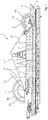
- FIG. 1 is designed as a surface watercraft military vessel 1 shown.
- the watercraft 1 has a hull 2, above which a main deck 6 is provided.
- a tower 4 is provided on the structure 3.
- the vessel 1 has a first directional weapon 7 arranged on an upper deck 5 in the region of the stern.
- a second directable weapon 8 is provided in the area of the bow on a main deck 6.
- the directable weapons 7, 8 are preferably in azimuth and / or elevation directable. According to the embodiment, the weapons 7, 8 are designed as guns.
- the watercraft 1 has a plurality of antennas 9, 10.
- the antennas 9, 10 are arranged according to the embodiment on the upper deck 5, but can also be arranged on another deck.
- the antennas 9, 10 are linear, rod-shaped antennas designed. In the in FIG. 1 illustrated, first position, the antennas 9, 10 are vertically aligned. The antennas are so far in the first position from the top of the vessel 1 from.
- the Elevationsricht Schemee the weapons 7, 8 are shown as brightly shaded angle ranges E1.
- the directional range of the weapon 7 is limited in elevation by the upright antennas 9. This means that the weapon 7, if it is directed in the direction of the bow, can only be directed above an imaginary connecting line L1 between the weapon 7 and the free end of the rear antenna 9 in elevation.
- the antenna 9 has an interference contour which restricts the directional range of the weapon 7.
- the antennas 9, 10 are pivotable from a first position, in which the antennas 9, 10 are arranged substantially vertically, into a second position, in which the height of the antennas 9, 10 is reduced to increase the directional range of the weapons 7, 8 relative to the first position.
- the antennas 9, 10 are formed pivotably via a pivoting device 11 arranged at the base of the antennas.
- the Elevationsricht Scheme the weapon 7 is shown as a dark shaded angle range E2. It can be seen that the elevation adjustment range of the weapon 7 in the second position of the antenna 9 is increased relative to the first position.
- the directional range of the weapon 7 is not limited in the second position of the antenna 9 by the antenna 9, but by the tower 4, cf. the imaginary connecting line L2 between the weapon 7 and the tower contour.
- the pivoting of the antennas 9 in the second position is preferably carried out when the weapon 7 assumes a predetermined Elevationsrichtgna and / or a predetermined Azimutrichtgna, so that the pivoting of the antennas 9 only takes place when the antennas 9 actually form an interference contour for the weapon 7 ,
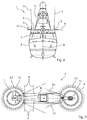
- FIG. 2 To illustrate the pivot plane of the antennas 9, 10 is in the FIG. 2 an antenna 9 shown in both the first, upright position and in the pivoted, second position.
- the antenna 9 In the second position, the antenna 9 is pivoted about 90 ° about a pivot axis S in a clockwise direction relative to the first position.
- the pivot plane of the antenna 9 is thus equal to the plane of the drawing and runs parallel to a transverse axis of the fuselage 2 or perpendicular to a longitudinal axis of the fuselage 2.
- the free end of the antenna 9 is arranged laterally of the fuselage 2.
- the pivot axis S is arranged in the edge region of the deck 5 and the antenna 9 is pivoted away in the second position of the tower 4 of the ship, the antenna 9 is in the second position substantially laterally of the fuselage 2.
- the overall width of the watercraft 1 increases so far the length of the antenna 9.
- the Figures 3 shows the antennas 9, 10 in the second, pivoted position, in which the antennas 9, 10 less restrict the directional range of the weapons 7, 8 than in the FIG. 1 shown first, upright position.
- the antennas 9, 10 In the second position, the antennas 9, 10 in a range of 45 ° to 120 °, preferably in a range of 70 ° to 110 °, more preferably pivoted about 90 ° relative to the first position.
- the antennas 9, 10 may be arranged horizontally in the second position, for example.
- the directional range of the weapons 7, 8 is limited in azimuth by the interference contours of the antennas 9, 10, cf. the brightly shaded angle ranges A1.
- the directional range of the weapons 7, 8 is increased in azimuth, cf. the dark shaded angle ranges A2.
- the antennas 9, 10 are each pivotable in a pivot plane, which forms an angle with the longitudinal axis R of the fuselage 2.
- the pivoting plane of the antennas 9 encloses an angle of approximately 90 ° with the longitudinal axis R of the fuselage 2.
- the antennas 10 are pivotable in a pivoting plane which runs parallel to an imaginary connecting line between the azimuth pointing axis of the weapon 8 and the base point of the antennas 10.
- the pivot plane of the antennas 10 is quasi "in the firing direction" of the weapon 8. This arrangement of the pivot plane is advantageous because the weapon 8 is disposed below the base of the antenna 10 and it is not possible, the antenna 10 completely out of the directional range of the weapon 8 to swing out.
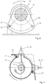
- a pivoting device 11 by means of which the antennas 9, 10 can be pivoted.
- the pivoting device 11, in particular a carrier plate 28 of the pivoting device 11, is rigidly connected to the deck 5 via a foundation 24.
- the pivoting device 11 has a shaft 13 which is rotatably mounted in two stationary bearings 12.
- a, in particular cylindrically shaped, receptacle 14 for the antenna 9, 10 is provided on the shaft 13 .
- the base of the antenna 9, 10 is added.
- On the shaft 13 is seated on a gear 22, which is connected via a toothed belt 15 with a drive 16.
- the drive 16 can be controlled via two, not shown in the figures, in particular mechanical, limit switches, so that the antenna 9, 10 can be pivoted back and forth by the drive 16 between the first position and the second position.
- contactless proximity switches can be provided for detecting the position of the shaft. By means of the proximity switches, a transmitter and / or receiver connected to the antenna 9, 10 can be switched off while the antenna 9, 10 is being pivoted, which is also referred to as "blanking".
- a cable 19 connection of the antenna 9, 10 is connected to a transmitter and / or a receiver.
- the cable 19 extends through the interior of the receptacle 14, emerges from the receptacle 14 and then extends helically around the shaft 13.
- the shaft 13 at least in the region in which the cable 19 extends around the shaft 13, a soft sheath on so that damage to the cable 19 can be reduced.
- the cable 19 extends through a arranged in the plane of the deck 5 tenter 23 into the interior of the structure 3 inside.
- FIG. 5 shows that the pivoting device 11 has a housing 20 which protects the mechanics of the pivoting device, in particular the shaft 13 from external influences.
- a seal 21 is provided between the housing 20 and the shaft 13, in particular the receptacle 14 of the shaft 13.
- a disc 26 is further arranged, which is rotatable with the shaft 13.
- the disc 26 has two recesses 25, which in the first and second positions of the antenna 9, 10 can receive a locking pin 18 to set the antenna 9, 10 in the respective position.
- the locking bolt is linearly movable by means of a, in particular electrically driven, cylinder 17.
- two disks 26 for locking the antenna 9, 10 are arranged on the shaft 13.
- FIG. 7 shows a sectional view through the receptacle 14 of the shaft 13. It can be seen that the seal 21, the housing 20 against the receptacle 14 seals.
- FIG. 8 a second embodiment of a pivoting device 11 for an antenna 9, 10 is shown.
- the pivoting device 11 is elastic with the deck 5 of the watercraft 1 connected.
- the pivoting device 11 on spring elements 27, which are arranged between a support plate 28 of the pivoting device and the deck 5.
- an adaptation device for adapting the antenna impedance can additionally be provided between the antenna 9, 10 and a transmitter and / or receiver.
- two operating states can be stored in the adaptation device, so that a first setting for the first position of the antenna 9, 10 and a second setting for the second position of the antenna 9, 10 can be stored. This makes it possible to use the antenna 9, 10 in the first position and in the second position for radio communication.
- the radiation behavior of the antenna 9, 10 can be influenced, as will be described below.
- the radiation angle of the antenna 9, 10 is rather flat, which is why reflections on the ionosphere only occur at a large distance from the watercraft 1 when electromagnetic waves are emitted in the HF range.
- the antenna 9, 10 has an improved radiation behavior for connections to distant receivers.
- the antenna 9, 10 is in a lowered, in particular horizontal position.
- the radiation angle of the antenna 9, 10 in the second position is rather steep, i. the main emission direction is substantially vertical. Electromagnetic waves in the HF range are therefore reflected above the vessel 1 at the ionosphere and thrown back into the vicinity of the vessel 1. This results in an improved radiation behavior for connections to near receivers.
- the antennas 9, 10 of the watercraft 1 can be continuously pivotable and / or lockable, so that the height-reduced, second position of the antennas 9, 10 is continuously adjustable.
- the pivoting position of the antennas 9, 10 in dependence on the Azimutricht ein and / or the Elevationsricht ein the weapons 7, 8 are set.
- the vessel 1 described above comprises a directionable weapon 7, 8 and an antenna 9, 10, which is pivotable from a first position, in which the antenna 9, 10 is arranged substantially vertically, in a second position, in which the height the antenna 9, 10 above the watercraft 1 to increase the directional range the weapon 7, 8 is reduced relative to the first position.
- the sweeping angle of the weapon 7, 8 can be increased by the pivoting of the antenna 9, 10 in its second position.
Landscapes
- Engineering & Computer Science (AREA)
- General Engineering & Computer Science (AREA)
- Aviation & Aerospace Engineering (AREA)
- Variable-Direction Aerials And Aerial Arrays (AREA)
- Details Of Aerials (AREA)
- Support Of Aerials (AREA)
Priority Applications (1)
| Application Number | Priority Date | Filing Date | Title |
|---|---|---|---|
| PL15754144T PL3204716T3 (pl) | 2014-10-08 | 2015-08-18 | Wojskowa jednostka pływająca |
Applications Claiming Priority (2)
| Application Number | Priority Date | Filing Date | Title |
|---|---|---|---|
| DE102014114571.2A DE102014114571B3 (de) | 2014-10-08 | 2014-10-08 | Militärisches Wasserfahrzeug |
| PCT/EP2015/068890 WO2016055206A1 (de) | 2014-10-08 | 2015-08-18 | Militärisches wasserfahrzeug |
Publications (2)
| Publication Number | Publication Date |
|---|---|
| EP3204716A1 EP3204716A1 (de) | 2017-08-16 |
| EP3204716B1 true EP3204716B1 (de) | 2018-10-10 |
Family
ID=54007681
Family Applications (1)
| Application Number | Title | Priority Date | Filing Date |
|---|---|---|---|
| EP15754144.2A Active EP3204716B1 (de) | 2014-10-08 | 2015-08-18 | Militärisches wasserfahrzeug |
Country Status (9)
| Country | Link |
|---|---|
| US (1) | US10247504B2 (pl) |
| EP (1) | EP3204716B1 (pl) |
| KR (1) | KR101790479B1 (pl) |
| AU (1) | AU2015330324B2 (pl) |
| DE (1) | DE102014114571B3 (pl) |
| ES (1) | ES2703354T3 (pl) |
| PL (1) | PL3204716T3 (pl) |
| TR (1) | TR201820832T4 (pl) |
| WO (1) | WO2016055206A1 (pl) |
Families Citing this family (2)
| Publication number | Priority date | Publication date | Assignee | Title |
|---|---|---|---|---|
| US10446901B1 (en) | 2018-10-16 | 2019-10-15 | Science Applications International Corporation | System and method for guarding an antenna from interfering physical objects |
| GB2590067B8 (en) * | 2019-11-14 | 2023-10-11 | Bae Systems Plc | A weapon system |
Family Cites Families (11)
| Publication number | Priority date | Publication date | Assignee | Title |
|---|---|---|---|---|
| US4004729A (en) * | 1975-11-07 | 1977-01-25 | Lockheed Electronics Co., Inc. | Automated fire control apparatus |
| DE2735241A1 (de) * | 1977-08-04 | 1979-02-15 | Vickers Ltd | Sicherheitsvorrichtung fuer abfeuerungsvorrichtungen |
| US4194432A (en) | 1977-11-25 | 1980-03-25 | Fmc Corporation | Apparatus for maximizing the firing field of a rotatable gun |
| US5227806A (en) * | 1991-03-20 | 1993-07-13 | Japan Radio Co., Ltd. | Stabilized ship antenna system for satellite communication |
| US8776664B2 (en) * | 2007-04-26 | 2014-07-15 | The United States Of America As Represented By The Secretary Of The Navy | Determination of weapons fratricide probability |
| KR100944905B1 (ko) * | 2007-12-28 | 2010-03-03 | 삼성중공업 주식회사 | 레이더 마스트 높이 조절 시스템 |
| US8207902B1 (en) * | 2009-01-13 | 2012-06-26 | The United States Of America As Represented By The Secretary Of Navy | Broadband HF ship mast cage antenna |
| EP2278659A1 (en) * | 2009-07-23 | 2011-01-26 | Thales Nederland B.V. | A broadband HF antenna fully integrated on a naval ship |
| KR20110055240A (ko) | 2009-11-19 | 2011-05-25 | 삼성테크윈 주식회사 | 원격조종무장 장치 |
| US9130264B2 (en) * | 2012-05-09 | 2015-09-08 | Jeffrey Gervais | Apparatus for raising and lowering antennae |
| KR101358228B1 (ko) | 2012-05-31 | 2014-02-05 | 삼성중공업 주식회사 | 선박의 레이더 마스트 |
-
2014
- 2014-10-08 DE DE102014114571.2A patent/DE102014114571B3/de not_active Expired - Fee Related
-
2015
- 2015-08-18 EP EP15754144.2A patent/EP3204716B1/de active Active
- 2015-08-18 PL PL15754144T patent/PL3204716T3/pl unknown
- 2015-08-18 TR TR2018/20832T patent/TR201820832T4/tr unknown
- 2015-08-18 AU AU2015330324A patent/AU2015330324B2/en active Active
- 2015-08-18 KR KR1020177007512A patent/KR101790479B1/ko active Active
- 2015-08-18 WO PCT/EP2015/068890 patent/WO2016055206A1/de not_active Ceased
- 2015-08-18 ES ES15754144T patent/ES2703354T3/es active Active
- 2015-08-18 US US15/516,702 patent/US10247504B2/en active Active
Non-Patent Citations (1)
| Title |
|---|
| None * |
Also Published As
| Publication number | Publication date |
|---|---|
| DE102014114571B3 (de) | 2015-12-24 |
| US10247504B2 (en) | 2019-04-02 |
| WO2016055206A1 (de) | 2016-04-14 |
| ES2703354T3 (es) | 2019-03-08 |
| AU2015330324A1 (en) | 2017-04-06 |
| AU2015330324B2 (en) | 2018-03-15 |
| KR20170044690A (ko) | 2017-04-25 |
| KR101790479B1 (ko) | 2017-10-25 |
| US20170299318A1 (en) | 2017-10-19 |
| EP3204716A1 (de) | 2017-08-16 |
| PL3204716T3 (pl) | 2019-03-29 |
| TR201820832T4 (tr) | 2019-01-21 |
Similar Documents
| Publication | Publication Date | Title |
|---|---|---|
| EP0027643B1 (de) | Einem mit Radar arbeitenden Ziel nachführbare Störsender-Richtantennenanordnung | |
| DE102010016560C5 (de) | Fahrzeug, insbesondere militärisches Kampffahrzeug | |
| EP0388762B1 (de) | Rüstsatz für militärische Kampffahrzeuge | |
| DE102013100392A1 (de) | Vorrichtung und Verfahren zum Richten eines Raketenabschussbehälters | |
| DE102014114571B3 (de) | Militärisches Wasserfahrzeug | |
| DE10128973C1 (de) | U-Boot | |
| DE10247350A1 (de) | Einrichtung zum Schutz von Objekten gegen als Lenk-Flugkörper ausgebildete Munitionen | |
| EP0844455B1 (de) | Anordnung eines Geschützes in einem Panzerturm | |
| DE2843943A1 (de) | Schiffsgeschuetz | |
| DE1428726A1 (de) | Feuerleitanlage | |
| DE10016781C2 (de) | Schutzvorrichtung | |
| EP1493657B1 (de) | Unterseeboot | |
| EP3120412B1 (de) | Vorrichtung zum senden- und/oder empfangen von elektromagnetischen wellen | |
| EP3201118B1 (de) | Wasserfahrzeug mit einem kran zum heben von lasten | |
| DE19730092C2 (de) | Lasttragendes Unterwasserfahrzeug | |
| DE102016101302A1 (de) | Schutzvorrichtung zum Schutz eines militärischen Fahrzeugs | |
| DE202022106653U1 (de) | Funkvermessungs-Flugdrohne | |
| DE102011116288B4 (de) | Unterwasserfahrzeug mit einem optischen Strahlenwirksystem | |
| EP4073457B1 (de) | Bewegliche schutzvorrichtung für militärische fahrzeuge mit abstandsaktivem schutzsystem | |
| DE102017109338A1 (de) | Unterwasserkörper mit einem hydrodynamischen element zum senden und/oder empfangen eines signals | |
| DE2550709A1 (de) | Passiver radarreflektor fuer anwendungen im bereich der luft- und schifffahrt | |
| DE3121142C1 (en) | Anti-tank gun on tracked carriage - has barrel offset from centre and with limited traverse | |
| DE2034529C1 (de) | Anlage zur elektromagnetischen Überwachung von Seegebieten mittels am Meeresboden ausgelegter ein- oder zweiadriger Kabel | |
| DE1303439B (pl) | ||
| DE1926305A1 (de) | Bordradaranlage fuer ein Unterseeboot |
Legal Events
| Date | Code | Title | Description |
|---|---|---|---|
| STAA | Information on the status of an ep patent application or granted ep patent |
Free format text: STATUS: THE INTERNATIONAL PUBLICATION HAS BEEN MADE |
|
| PUAI | Public reference made under article 153(3) epc to a published international application that has entered the european phase |
Free format text: ORIGINAL CODE: 0009012 |
|
| STAA | Information on the status of an ep patent application or granted ep patent |
Free format text: STATUS: REQUEST FOR EXAMINATION WAS MADE |
|
| 17P | Request for examination filed |
Effective date: 20170118 |
|
| AK | Designated contracting states |
Kind code of ref document: A1 Designated state(s): AL AT BE BG CH CY CZ DE DK EE ES FI FR GB GR HR HU IE IS IT LI LT LU LV MC MK MT NL NO PL PT RO RS SE SI SK SM TR |
|
| AX | Request for extension of the european patent |
Extension state: BA ME |
|
| DAV | Request for validation of the european patent (deleted) | ||
| DAX | Request for extension of the european patent (deleted) | ||
| GRAP | Despatch of communication of intention to grant a patent |
Free format text: ORIGINAL CODE: EPIDOSNIGR1 |
|
| STAA | Information on the status of an ep patent application or granted ep patent |
Free format text: STATUS: GRANT OF PATENT IS INTENDED |
|
| INTG | Intention to grant announced |
Effective date: 20180502 |
|
| GRAS | Grant fee paid |
Free format text: ORIGINAL CODE: EPIDOSNIGR3 |
|
| GRAA | (expected) grant |
Free format text: ORIGINAL CODE: 0009210 |
|
| STAA | Information on the status of an ep patent application or granted ep patent |
Free format text: STATUS: THE PATENT HAS BEEN GRANTED |
|
| AK | Designated contracting states |
Kind code of ref document: B1 Designated state(s): AL AT BE BG CH CY CZ DE DK EE ES FI FR GB GR HR HU IE IS IT LI LT LU LV MC MK MT NL NO PL PT RO RS SE SI SK SM TR |
|
| REG | Reference to a national code |
Ref country code: GB Ref legal event code: FG4D Free format text: NOT ENGLISH |
|
| REG | Reference to a national code |
Ref country code: AT Ref legal event code: REF Ref document number: 1051744 Country of ref document: AT Kind code of ref document: T Effective date: 20181015 Ref country code: CH Ref legal event code: EP |
|
| REG | Reference to a national code |
Ref country code: IE Ref legal event code: FG4D Free format text: LANGUAGE OF EP DOCUMENT: GERMAN |
|
| REG | Reference to a national code |
Ref country code: DE Ref legal event code: R096 Ref document number: 502015006372 Country of ref document: DE |
|
| REG | Reference to a national code |
Ref country code: DE Ref legal event code: R084 Ref document number: 502015006372 Country of ref document: DE |
|
| REG | Reference to a national code |
Ref country code: NL Ref legal event code: FP |
|
| REG | Reference to a national code |
Ref country code: SE Ref legal event code: TRGR |
|
| REG | Reference to a national code |
Ref country code: NO Ref legal event code: T2 Effective date: 20181010 Ref country code: LT Ref legal event code: MG4D |
|
| REG | Reference to a national code |
Ref country code: ES Ref legal event code: FG2A Ref document number: 2703354 Country of ref document: ES Kind code of ref document: T3 Effective date: 20190308 |
|
| PG25 | Lapsed in a contracting state [announced via postgrant information from national office to epo] |
Ref country code: LV Free format text: LAPSE BECAUSE OF FAILURE TO SUBMIT A TRANSLATION OF THE DESCRIPTION OR TO PAY THE FEE WITHIN THE PRESCRIBED TIME-LIMIT Effective date: 20181010 Ref country code: HR Free format text: LAPSE BECAUSE OF FAILURE TO SUBMIT A TRANSLATION OF THE DESCRIPTION OR TO PAY THE FEE WITHIN THE PRESCRIBED TIME-LIMIT Effective date: 20181010 Ref country code: BG Free format text: LAPSE BECAUSE OF FAILURE TO SUBMIT A TRANSLATION OF THE DESCRIPTION OR TO PAY THE FEE WITHIN THE PRESCRIBED TIME-LIMIT Effective date: 20190110 Ref country code: FI Free format text: LAPSE BECAUSE OF FAILURE TO SUBMIT A TRANSLATION OF THE DESCRIPTION OR TO PAY THE FEE WITHIN THE PRESCRIBED TIME-LIMIT Effective date: 20181010 Ref country code: IS Free format text: LAPSE BECAUSE OF FAILURE TO SUBMIT A TRANSLATION OF THE DESCRIPTION OR TO PAY THE FEE WITHIN THE PRESCRIBED TIME-LIMIT Effective date: 20190210 Ref country code: LT Free format text: LAPSE BECAUSE OF FAILURE TO SUBMIT A TRANSLATION OF THE DESCRIPTION OR TO PAY THE FEE WITHIN THE PRESCRIBED TIME-LIMIT Effective date: 20181010 |
|
| PG25 | Lapsed in a contracting state [announced via postgrant information from national office to epo] |
Ref country code: GR Free format text: LAPSE BECAUSE OF FAILURE TO SUBMIT A TRANSLATION OF THE DESCRIPTION OR TO PAY THE FEE WITHIN THE PRESCRIBED TIME-LIMIT Effective date: 20190111 Ref country code: PT Free format text: LAPSE BECAUSE OF FAILURE TO SUBMIT A TRANSLATION OF THE DESCRIPTION OR TO PAY THE FEE WITHIN THE PRESCRIBED TIME-LIMIT Effective date: 20190210 Ref country code: AL Free format text: LAPSE BECAUSE OF FAILURE TO SUBMIT A TRANSLATION OF THE DESCRIPTION OR TO PAY THE FEE WITHIN THE PRESCRIBED TIME-LIMIT Effective date: 20181010 Ref country code: RS Free format text: LAPSE BECAUSE OF FAILURE TO SUBMIT A TRANSLATION OF THE DESCRIPTION OR TO PAY THE FEE WITHIN THE PRESCRIBED TIME-LIMIT Effective date: 20181010 |
|
| REG | Reference to a national code |
Ref country code: DE Ref legal event code: R097 Ref document number: 502015006372 Country of ref document: DE |
|
| PG25 | Lapsed in a contracting state [announced via postgrant information from national office to epo] |
Ref country code: CZ Free format text: LAPSE BECAUSE OF FAILURE TO SUBMIT A TRANSLATION OF THE DESCRIPTION OR TO PAY THE FEE WITHIN THE PRESCRIBED TIME-LIMIT Effective date: 20181010 Ref country code: DK Free format text: LAPSE BECAUSE OF FAILURE TO SUBMIT A TRANSLATION OF THE DESCRIPTION OR TO PAY THE FEE WITHIN THE PRESCRIBED TIME-LIMIT Effective date: 20181010 |
|
| PLBE | No opposition filed within time limit |
Free format text: ORIGINAL CODE: 0009261 |
|
| STAA | Information on the status of an ep patent application or granted ep patent |
Free format text: STATUS: NO OPPOSITION FILED WITHIN TIME LIMIT |
|
| PG25 | Lapsed in a contracting state [announced via postgrant information from national office to epo] |
Ref country code: SK Free format text: LAPSE BECAUSE OF FAILURE TO SUBMIT A TRANSLATION OF THE DESCRIPTION OR TO PAY THE FEE WITHIN THE PRESCRIBED TIME-LIMIT Effective date: 20181010 Ref country code: EE Free format text: LAPSE BECAUSE OF FAILURE TO SUBMIT A TRANSLATION OF THE DESCRIPTION OR TO PAY THE FEE WITHIN THE PRESCRIBED TIME-LIMIT Effective date: 20181010 Ref country code: SM Free format text: LAPSE BECAUSE OF FAILURE TO SUBMIT A TRANSLATION OF THE DESCRIPTION OR TO PAY THE FEE WITHIN THE PRESCRIBED TIME-LIMIT Effective date: 20181010 Ref country code: RO Free format text: LAPSE BECAUSE OF FAILURE TO SUBMIT A TRANSLATION OF THE DESCRIPTION OR TO PAY THE FEE WITHIN THE PRESCRIBED TIME-LIMIT Effective date: 20181010 |
|
| 26N | No opposition filed |
Effective date: 20190711 |
|
| REG | Reference to a national code |
Ref country code: DE Ref legal event code: R081 Ref document number: 502015006372 Country of ref document: DE Owner name: THYSSENKRUPP AG, DE Free format text: FORMER OWNERS: THYSSENKRUPP AG, 45143 ESSEN, DE; THYSSENKRUPP MARINE SYSTEMS GMBH, 24143 KIEL, DE Ref country code: DE Ref legal event code: R081 Ref document number: 502015006372 Country of ref document: DE Owner name: THYSSENKRUPP MARINE SYSTEMS GMBH, DE Free format text: FORMER OWNERS: THYSSENKRUPP AG, 45143 ESSEN, DE; THYSSENKRUPP MARINE SYSTEMS GMBH, 24143 KIEL, DE |
|
| PG25 | Lapsed in a contracting state [announced via postgrant information from national office to epo] |
Ref country code: SI Free format text: LAPSE BECAUSE OF FAILURE TO SUBMIT A TRANSLATION OF THE DESCRIPTION OR TO PAY THE FEE WITHIN THE PRESCRIBED TIME-LIMIT Effective date: 20181010 |
|
| PG25 | Lapsed in a contracting state [announced via postgrant information from national office to epo] |
Ref country code: LU Free format text: LAPSE BECAUSE OF NON-PAYMENT OF DUE FEES Effective date: 20190818 Ref country code: CH Free format text: LAPSE BECAUSE OF NON-PAYMENT OF DUE FEES Effective date: 20190831 Ref country code: MC Free format text: LAPSE BECAUSE OF FAILURE TO SUBMIT A TRANSLATION OF THE DESCRIPTION OR TO PAY THE FEE WITHIN THE PRESCRIBED TIME-LIMIT Effective date: 20181010 Ref country code: LI Free format text: LAPSE BECAUSE OF NON-PAYMENT OF DUE FEES Effective date: 20190831 |
|
| REG | Reference to a national code |
Ref country code: BE Ref legal event code: MM Effective date: 20190831 |
|
| PG25 | Lapsed in a contracting state [announced via postgrant information from national office to epo] |
Ref country code: IE Free format text: LAPSE BECAUSE OF NON-PAYMENT OF DUE FEES Effective date: 20190818 |
|
| PG25 | Lapsed in a contracting state [announced via postgrant information from national office to epo] |
Ref country code: BE Free format text: LAPSE BECAUSE OF NON-PAYMENT OF DUE FEES Effective date: 20190831 |
|
| PG25 | Lapsed in a contracting state [announced via postgrant information from national office to epo] |
Ref country code: CY Free format text: LAPSE BECAUSE OF FAILURE TO SUBMIT A TRANSLATION OF THE DESCRIPTION OR TO PAY THE FEE WITHIN THE PRESCRIBED TIME-LIMIT Effective date: 20181010 |
|
| PG25 | Lapsed in a contracting state [announced via postgrant information from national office to epo] |
Ref country code: MT Free format text: LAPSE BECAUSE OF FAILURE TO SUBMIT A TRANSLATION OF THE DESCRIPTION OR TO PAY THE FEE WITHIN THE PRESCRIBED TIME-LIMIT Effective date: 20181010 Ref country code: HU Free format text: LAPSE BECAUSE OF FAILURE TO SUBMIT A TRANSLATION OF THE DESCRIPTION OR TO PAY THE FEE WITHIN THE PRESCRIBED TIME-LIMIT; INVALID AB INITIO Effective date: 20150818 |
|
| REG | Reference to a national code |
Ref country code: AT Ref legal event code: MM01 Ref document number: 1051744 Country of ref document: AT Kind code of ref document: T Effective date: 20200818 |
|
| PG25 | Lapsed in a contracting state [announced via postgrant information from national office to epo] |
Ref country code: AT Free format text: LAPSE BECAUSE OF NON-PAYMENT OF DUE FEES Effective date: 20200818 |
|
| PG25 | Lapsed in a contracting state [announced via postgrant information from national office to epo] |
Ref country code: MK Free format text: LAPSE BECAUSE OF FAILURE TO SUBMIT A TRANSLATION OF THE DESCRIPTION OR TO PAY THE FEE WITHIN THE PRESCRIBED TIME-LIMIT Effective date: 20181010 |
|
| REG | Reference to a national code |
Ref country code: DE Ref legal event code: R081 Ref document number: 502015006372 Country of ref document: DE Owner name: THYSSENKRUPP AG, DE Free format text: FORMER OWNERS: THYSSENKRUPP AG, 45143 ESSEN, DE; THYSSENKRUPP MARINE SYSTEMS GMBH, 24143 KIEL, DE Ref country code: DE Ref legal event code: R081 Ref document number: 502015006372 Country of ref document: DE Owner name: TKMS GMBH, DE Free format text: FORMER OWNERS: THYSSENKRUPP AG, 45143 ESSEN, DE; THYSSENKRUPP MARINE SYSTEMS GMBH, 24143 KIEL, DE |
|
| PGFP | Annual fee paid to national office [announced via postgrant information from national office to epo] |
Ref country code: NL Payment date: 20250821 Year of fee payment: 11 |
|
| PGFP | Annual fee paid to national office [announced via postgrant information from national office to epo] |
Ref country code: ES Payment date: 20250926 Year of fee payment: 11 |
|
| PGFP | Annual fee paid to national office [announced via postgrant information from national office to epo] |
Ref country code: DE Payment date: 20250820 Year of fee payment: 11 |
|
| PGFP | Annual fee paid to national office [announced via postgrant information from national office to epo] |
Ref country code: NO Payment date: 20250826 Year of fee payment: 11 |
|
| PGFP | Annual fee paid to national office [announced via postgrant information from national office to epo] |
Ref country code: PL Payment date: 20250811 Year of fee payment: 11 Ref country code: TR Payment date: 20250812 Year of fee payment: 11 Ref country code: IT Payment date: 20250825 Year of fee payment: 11 |
|
| PGFP | Annual fee paid to national office [announced via postgrant information from national office to epo] |
Ref country code: GB Payment date: 20250821 Year of fee payment: 11 |
|
| PGFP | Annual fee paid to national office [announced via postgrant information from national office to epo] |
Ref country code: FR Payment date: 20250829 Year of fee payment: 11 |
|
| PGFP | Annual fee paid to national office [announced via postgrant information from national office to epo] |
Ref country code: SE Payment date: 20250820 Year of fee payment: 11 |