EP3204533B1 - Système et procédé de décomposition de l'eau - Google Patents
Système et procédé de décomposition de l'eau Download PDFInfo
- Publication number
- EP3204533B1 EP3204533B1 EP15849585.3A EP15849585A EP3204533B1 EP 3204533 B1 EP3204533 B1 EP 3204533B1 EP 15849585 A EP15849585 A EP 15849585A EP 3204533 B1 EP3204533 B1 EP 3204533B1
- Authority
- EP
- European Patent Office
- Prior art keywords
- electrode
- chiral
- electrons
- substrate
- molecules
- Prior art date
- Legal status (The legal status is an assumption and is not a legal conclusion. Google has not performed a legal analysis and makes no representation as to the accuracy of the status listed.)
- Active
Links
- XLYOFNOQVPJJNP-UHFFFAOYSA-N water Substances O XLYOFNOQVPJJNP-UHFFFAOYSA-N 0.000 title claims description 53
- 238000000034 method Methods 0.000 title claims description 40
- UFHFLCQGNIYNRP-UHFFFAOYSA-N Hydrogen Chemical compound [H][H] UFHFLCQGNIYNRP-UHFFFAOYSA-N 0.000 claims description 63
- 239000001257 hydrogen Substances 0.000 claims description 61
- 229910052739 hydrogen Inorganic materials 0.000 claims description 61
- 239000002105 nanoparticle Substances 0.000 claims description 39
- 239000000758 substrate Substances 0.000 claims description 35
- 230000003647 oxidation Effects 0.000 claims description 28
- 238000007254 oxidation reaction Methods 0.000 claims description 28
- 108010038807 Oligopeptides Proteins 0.000 claims description 23
- 102000015636 Oligopeptides Human genes 0.000 claims description 23
- 230000008569 process Effects 0.000 claims description 23
- 239000003792 electrolyte Substances 0.000 claims description 18
- 230000015572 biosynthetic process Effects 0.000 claims description 12
- 239000010410 layer Substances 0.000 claims description 12
- 239000004065 semiconductor Substances 0.000 claims description 11
- 230000009467 reduction Effects 0.000 claims description 10
- 230000005284 excitation Effects 0.000 claims description 8
- 238000012546 transfer Methods 0.000 claims description 7
- 150000002500 ions Chemical class 0.000 claims description 6
- 239000013545 self-assembled monolayer Substances 0.000 claims description 5
- -1 hydrogen ions Chemical class 0.000 claims description 4
- 239000002184 metal Substances 0.000 claims description 4
- 229910052751 metal Inorganic materials 0.000 claims description 4
- 150000001413 amino acids Chemical class 0.000 claims description 3
- 229920001940 conductive polymer Polymers 0.000 claims description 3
- 229920000642 polymer Polymers 0.000 claims description 3
- 239000002094 self assembled monolayer Substances 0.000 claims description 3
- GWEVSGVZZGPLCZ-UHFFFAOYSA-N Titan oxide Chemical compound O=[Ti]=O GWEVSGVZZGPLCZ-UHFFFAOYSA-N 0.000 description 98
- 238000004519 manufacturing process Methods 0.000 description 34
- UHYPYGJEEGLRJD-UHFFFAOYSA-N cadmium(2+);selenium(2-) Chemical compound [Se-2].[Cd+2] UHYPYGJEEGLRJD-UHFFFAOYSA-N 0.000 description 30
- 108020004414 DNA Proteins 0.000 description 24
- 238000006243 chemical reaction Methods 0.000 description 24
- QVGXLLKOCUKJST-UHFFFAOYSA-N atomic oxygen Chemical compound [O] QVGXLLKOCUKJST-UHFFFAOYSA-N 0.000 description 20
- 229910052760 oxygen Inorganic materials 0.000 description 20
- 239000001301 oxygen Substances 0.000 description 20
- 230000005283 ground state Effects 0.000 description 15
- 229910021607 Silver chloride Inorganic materials 0.000 description 14
- PXHVJJICTQNCMI-UHFFFAOYSA-N Nickel Chemical compound [Ni] PXHVJJICTQNCMI-UHFFFAOYSA-N 0.000 description 13
- 238000005259 measurement Methods 0.000 description 13
- HKZLPVFGJNLROG-UHFFFAOYSA-M silver monochloride Chemical compound [Cl-].[Ag+] HKZLPVFGJNLROG-UHFFFAOYSA-M 0.000 description 12
- 239000000243 solution Substances 0.000 description 12
- 102000053602 DNA Human genes 0.000 description 10
- 239000002356 single layer Substances 0.000 description 10
- ZMXDDKWLCZADIW-UHFFFAOYSA-N N,N-Dimethylformamide Chemical compound CN(C)C=O ZMXDDKWLCZADIW-UHFFFAOYSA-N 0.000 description 9
- YXFVVABEGXRONW-UHFFFAOYSA-N Toluene Chemical compound CC1=CC=CC=C1 YXFVVABEGXRONW-UHFFFAOYSA-N 0.000 description 9
- 125000004429 atom Chemical group 0.000 description 9
- 230000000694 effects Effects 0.000 description 9
- 239000007789 gas Substances 0.000 description 8
- MYMOFIZGZYHOMD-UHFFFAOYSA-N Dioxygen Chemical compound O=O MYMOFIZGZYHOMD-UHFFFAOYSA-N 0.000 description 7
- 239000000523 sample Substances 0.000 description 7
- LFQSCWFLJHTTHZ-UHFFFAOYSA-N Ethanol Chemical compound CCO LFQSCWFLJHTTHZ-UHFFFAOYSA-N 0.000 description 6
- 238000004817 gas chromatography Methods 0.000 description 6
- 230000027756 respiratory electron transport chain Effects 0.000 description 6
- 238000003917 TEM image Methods 0.000 description 5
- 230000004888 barrier function Effects 0.000 description 5
- VDQVEACBQKUUSU-UHFFFAOYSA-M disodium;sulfanide Chemical compound [Na+].[Na+].[SH-] VDQVEACBQKUUSU-UHFFFAOYSA-M 0.000 description 5
- 230000010287 polarization Effects 0.000 description 5
- 229910052979 sodium sulfide Inorganic materials 0.000 description 5
- NINIDFKCEFEMDL-UHFFFAOYSA-N Sulfur Chemical compound [S] NINIDFKCEFEMDL-UHFFFAOYSA-N 0.000 description 4
- 230000005540 biological transmission Effects 0.000 description 4
- 239000006185 dispersion Substances 0.000 description 4
- 238000001652 electrophoretic deposition Methods 0.000 description 4
- 150000002431 hydrogen Chemical class 0.000 description 4
- 239000000463 material Substances 0.000 description 4
- 239000000203 mixture Substances 0.000 description 4
- 125000004430 oxygen atom Chemical group O* 0.000 description 4
- 230000001443 photoexcitation Effects 0.000 description 4
- GEHJYWRUCIMESM-UHFFFAOYSA-L sodium sulfite Chemical compound [Na+].[Na+].[O-]S([O-])=O GEHJYWRUCIMESM-UHFFFAOYSA-L 0.000 description 4
- 229910052717 sulfur Inorganic materials 0.000 description 4
- 239000011593 sulfur Substances 0.000 description 4
- IJGRMHOSHXDMSA-UHFFFAOYSA-N Atomic nitrogen Chemical compound N#N IJGRMHOSHXDMSA-UHFFFAOYSA-N 0.000 description 3
- 108020004635 Complementary DNA Proteins 0.000 description 3
- KKEYFWRCBNTPAC-UHFFFAOYSA-N Terephthalic acid Chemical compound OC(=O)C1=CC=C(C(O)=O)C=C1 KKEYFWRCBNTPAC-UHFFFAOYSA-N 0.000 description 3
- ZMANZCXQSJIPKH-UHFFFAOYSA-N Triethylamine Chemical compound CCN(CC)CC ZMANZCXQSJIPKH-UHFFFAOYSA-N 0.000 description 3
- 238000013459 approach Methods 0.000 description 3
- 238000010804 cDNA synthesis Methods 0.000 description 3
- 238000000970 chrono-amperometry Methods 0.000 description 3
- 239000002299 complementary DNA Substances 0.000 description 3
- 239000004020 conductor Substances 0.000 description 3
- 238000000354 decomposition reaction Methods 0.000 description 3
- 239000008367 deionised water Substances 0.000 description 3
- 229910001873 dinitrogen Inorganic materials 0.000 description 3
- 238000005286 illumination Methods 0.000 description 3
- 229910052759 nickel Inorganic materials 0.000 description 3
- 239000002245 particle Substances 0.000 description 3
- 239000002516 radical scavenger Substances 0.000 description 3
- CSCPPACGZOOCGX-UHFFFAOYSA-N Acetone Chemical compound CC(C)=O CSCPPACGZOOCGX-UHFFFAOYSA-N 0.000 description 2
- 238000004566 IR spectroscopy Methods 0.000 description 2
- KFZMGEQAYNKOFK-UHFFFAOYSA-N Isopropanol Chemical compound CC(C)O KFZMGEQAYNKOFK-UHFFFAOYSA-N 0.000 description 2
- 108020004682 Single-Stranded DNA Proteins 0.000 description 2
- 150000001408 amides Chemical class 0.000 description 2
- 239000007864 aqueous solution Substances 0.000 description 2
- 238000005842 biochemical reaction Methods 0.000 description 2
- 238000009835 boiling Methods 0.000 description 2
- 125000003178 carboxy group Chemical group [H]OC(*)=O 0.000 description 2
- 239000003054 catalyst Substances 0.000 description 2
- 230000001276 controlling effect Effects 0.000 description 2
- 230000002596 correlated effect Effects 0.000 description 2
- 238000000151 deposition Methods 0.000 description 2
- 230000005611 electricity Effects 0.000 description 2
- 238000005516 engineering process Methods 0.000 description 2
- 238000002474 experimental method Methods 0.000 description 2
- 125000000524 functional group Chemical group 0.000 description 2
- 238000011534 incubation Methods 0.000 description 2
- 230000003993 interaction Effects 0.000 description 2
- VNWKTOKETHGBQD-UHFFFAOYSA-N methane Chemical compound C VNWKTOKETHGBQD-UHFFFAOYSA-N 0.000 description 2
- 230000037361 pathway Effects 0.000 description 2
- 239000008363 phosphate buffer Substances 0.000 description 2
- 108010054442 polyalanine Proteins 0.000 description 2
- 230000005855 radiation Effects 0.000 description 2
- 230000029058 respiratory gaseous exchange Effects 0.000 description 2
- 238000001179 sorption measurement Methods 0.000 description 2
- 238000004611 spectroscopical analysis Methods 0.000 description 2
- 238000001228 spectrum Methods 0.000 description 2
- 229910001220 stainless steel Inorganic materials 0.000 description 2
- 239000010935 stainless steel Substances 0.000 description 2
- 239000000126 substance Substances 0.000 description 2
- 239000000725 suspension Substances 0.000 description 2
- 125000003396 thiol group Chemical group [H]S* 0.000 description 2
- XOLBLPGZBRYERU-UHFFFAOYSA-N tin dioxide Chemical compound O=[Sn]=O XOLBLPGZBRYERU-UHFFFAOYSA-N 0.000 description 2
- 229910001887 tin oxide Inorganic materials 0.000 description 2
- 238000012876 topography Methods 0.000 description 2
- OKTJSMMVPCPJKN-UHFFFAOYSA-N Carbon Chemical compound [C] OKTJSMMVPCPJKN-UHFFFAOYSA-N 0.000 description 1
- RYGMFSIKBFXOCR-UHFFFAOYSA-N Copper Chemical compound [Cu] RYGMFSIKBFXOCR-UHFFFAOYSA-N 0.000 description 1
- BWGNESOTFCXPMA-UHFFFAOYSA-N Dihydrogen disulfide Chemical compound SS BWGNESOTFCXPMA-UHFFFAOYSA-N 0.000 description 1
- 238000005033 Fourier transform infrared spectroscopy Methods 0.000 description 1
- 239000007832 Na2SO4 Substances 0.000 description 1
- 108091028043 Nucleic acid sequence Proteins 0.000 description 1
- 108091034117 Oligonucleotide Proteins 0.000 description 1
- PMZURENOXWZQFD-UHFFFAOYSA-L Sodium Sulfate Chemical compound [Na+].[Na+].[O-]S([O-])(=O)=O PMZURENOXWZQFD-UHFFFAOYSA-L 0.000 description 1
- UCKMPCXJQFINFW-UHFFFAOYSA-N Sulphide Chemical compound [S-2] UCKMPCXJQFINFW-UHFFFAOYSA-N 0.000 description 1
- 238000007605 air drying Methods 0.000 description 1
- 125000000217 alkyl group Chemical group 0.000 description 1
- 238000010976 amide bond formation reaction Methods 0.000 description 1
- 125000003277 amino group Chemical group 0.000 description 1
- 238000004458 analytical method Methods 0.000 description 1
- 150000001450 anions Chemical class 0.000 description 1
- 238000004630 atomic force microscopy Methods 0.000 description 1
- 238000005452 bending Methods 0.000 description 1
- 230000031018 biological processes and functions Effects 0.000 description 1
- 239000006227 byproduct Substances 0.000 description 1
- 229910052799 carbon Inorganic materials 0.000 description 1
- 239000012159 carrier gas Substances 0.000 description 1
- 238000005266 casting Methods 0.000 description 1
- 238000001311 chemical methods and process Methods 0.000 description 1
- 239000003153 chemical reaction reagent Substances 0.000 description 1
- 239000003034 coal gas Substances 0.000 description 1
- 239000011248 coating agent Substances 0.000 description 1
- 238000000576 coating method Methods 0.000 description 1
- 238000001124 conductive atomic force microscopy Methods 0.000 description 1
- 229910052802 copper Inorganic materials 0.000 description 1
- 239000010949 copper Substances 0.000 description 1
- 230000008878 coupling Effects 0.000 description 1
- 238000010168 coupling process Methods 0.000 description 1
- 238000005859 coupling reaction Methods 0.000 description 1
- 230000006378 damage Effects 0.000 description 1
- 230000007423 decrease Effects 0.000 description 1
- 230000001419 dependent effect Effects 0.000 description 1
- 230000008021 deposition Effects 0.000 description 1
- 238000009826 distribution Methods 0.000 description 1
- 150000002019 disulfides Chemical class 0.000 description 1
- MAHNFPMIPQKPPI-UHFFFAOYSA-N disulfur Chemical compound S=S MAHNFPMIPQKPPI-UHFFFAOYSA-N 0.000 description 1
- 238000005868 electrolysis reaction Methods 0.000 description 1
- 239000008151 electrolyte solution Substances 0.000 description 1
- 230000002708 enhancing effect Effects 0.000 description 1
- 230000005281 excited state Effects 0.000 description 1
- 239000003574 free electron Substances 0.000 description 1
- 239000000446 fuel Substances 0.000 description 1
- 239000011521 glass Substances 0.000 description 1
- 238000003384 imaging method Methods 0.000 description 1
- 238000001566 impedance spectroscopy Methods 0.000 description 1
- 230000028161 membrane depolarization Effects 0.000 description 1
- 150000002739 metals Chemical class 0.000 description 1
- 238000002156 mixing Methods 0.000 description 1
- 230000004048 modification Effects 0.000 description 1
- 238000012986 modification Methods 0.000 description 1
- 239000002052 molecular layer Substances 0.000 description 1
- 239000002808 molecular sieve Substances 0.000 description 1
- 239000003345 natural gas Substances 0.000 description 1
- 230000001590 oxidative effect Effects 0.000 description 1
- 125000002467 phosphate group Chemical group [H]OP(=O)(O[H])O[*] 0.000 description 1
- 231100000289 photo-effect Toxicity 0.000 description 1
- 230000029553 photosynthesis Effects 0.000 description 1
- 238000010672 photosynthesis Methods 0.000 description 1
- 150000004032 porphyrins Chemical class 0.000 description 1
- 238000005182 potential energy surface Methods 0.000 description 1
- 239000000843 powder Substances 0.000 description 1
- 108090000765 processed proteins & peptides Proteins 0.000 description 1
- 150000003839 salts Chemical class 0.000 description 1
- 229920006395 saturated elastomer Polymers 0.000 description 1
- URGAHOPLAPQHLN-UHFFFAOYSA-N sodium aluminosilicate Chemical compound [Na+].[Al+3].[O-][Si]([O-])=O.[O-][Si]([O-])=O URGAHOPLAPQHLN-UHFFFAOYSA-N 0.000 description 1
- 229910052938 sodium sulfate Inorganic materials 0.000 description 1
- 241000894007 species Species 0.000 description 1
- 239000011550 stock solution Substances 0.000 description 1
- 150000004763 sulfides Chemical class 0.000 description 1
- 230000036967 uncompetitive effect Effects 0.000 description 1
Images


Classifications
-
- C—CHEMISTRY; METALLURGY
- C25—ELECTROLYTIC OR ELECTROPHORETIC PROCESSES; APPARATUS THEREFOR
- C25B—ELECTROLYTIC OR ELECTROPHORETIC PROCESSES FOR THE PRODUCTION OF COMPOUNDS OR NON-METALS; APPARATUS THEREFOR
- C25B1/00—Electrolytic production of inorganic compounds or non-metals
- C25B1/01—Products
- C25B1/02—Hydrogen or oxygen
- C25B1/04—Hydrogen or oxygen by electrolysis of water
-
- C—CHEMISTRY; METALLURGY
- C25—ELECTROLYTIC OR ELECTROPHORETIC PROCESSES; APPARATUS THEREFOR
- C25B—ELECTROLYTIC OR ELECTROPHORETIC PROCESSES FOR THE PRODUCTION OF COMPOUNDS OR NON-METALS; APPARATUS THEREFOR
- C25B1/00—Electrolytic production of inorganic compounds or non-metals
- C25B1/50—Processes
- C25B1/55—Photoelectrolysis
-
- C—CHEMISTRY; METALLURGY
- C25—ELECTROLYTIC OR ELECTROPHORETIC PROCESSES; APPARATUS THEREFOR
- C25B—ELECTROLYTIC OR ELECTROPHORETIC PROCESSES FOR THE PRODUCTION OF COMPOUNDS OR NON-METALS; APPARATUS THEREFOR
- C25B11/00—Electrodes; Manufacture thereof not otherwise provided for
- C25B11/04—Electrodes; Manufacture thereof not otherwise provided for characterised by the material
- C25B11/051—Electrodes formed of electrocatalysts on a substrate or carrier
- C25B11/073—Electrodes formed of electrocatalysts on a substrate or carrier characterised by the electrocatalyst material
-
- H—ELECTRICITY
- H01—ELECTRIC ELEMENTS
- H01G—CAPACITORS; CAPACITORS, RECTIFIERS, DETECTORS, SWITCHING DEVICES, LIGHT-SENSITIVE OR TEMPERATURE-SENSITIVE DEVICES OF THE ELECTROLYTIC TYPE
- H01G9/00—Electrolytic capacitors, rectifiers, detectors, switching devices, light-sensitive or temperature-sensitive devices; Processes of their manufacture
- H01G9/20—Light-sensitive devices
- H01G9/2027—Light-sensitive devices comprising an oxide semiconductor electrode
- H01G9/2031—Light-sensitive devices comprising an oxide semiconductor electrode comprising titanium oxide, e.g. TiO2
-
- H—ELECTRICITY
- H01—ELECTRIC ELEMENTS
- H01G—CAPACITORS; CAPACITORS, RECTIFIERS, DETECTORS, SWITCHING DEVICES, LIGHT-SENSITIVE OR TEMPERATURE-SENSITIVE DEVICES OF THE ELECTROLYTIC TYPE
- H01G9/00—Electrolytic capacitors, rectifiers, detectors, switching devices, light-sensitive or temperature-sensitive devices; Processes of their manufacture
- H01G9/20—Light-sensitive devices
- H01G9/2054—Light-sensitive devices comprising a semiconductor electrode comprising AII-BVI compounds, e.g. CdTe, CdSe, ZnTe, ZnSe, with or without impurities, e.g. doping materials
-
- Y—GENERAL TAGGING OF NEW TECHNOLOGICAL DEVELOPMENTS; GENERAL TAGGING OF CROSS-SECTIONAL TECHNOLOGIES SPANNING OVER SEVERAL SECTIONS OF THE IPC; TECHNICAL SUBJECTS COVERED BY FORMER USPC CROSS-REFERENCE ART COLLECTIONS [XRACs] AND DIGESTS
- Y02—TECHNOLOGIES OR APPLICATIONS FOR MITIGATION OR ADAPTATION AGAINST CLIMATE CHANGE
- Y02E—REDUCTION OF GREENHOUSE GAS [GHG] EMISSIONS, RELATED TO ENERGY GENERATION, TRANSMISSION OR DISTRIBUTION
- Y02E10/00—Energy generation through renewable energy sources
- Y02E10/50—Photovoltaic [PV] energy
- Y02E10/542—Dye sensitized solar cells
-
- Y—GENERAL TAGGING OF NEW TECHNOLOGICAL DEVELOPMENTS; GENERAL TAGGING OF CROSS-SECTIONAL TECHNOLOGIES SPANNING OVER SEVERAL SECTIONS OF THE IPC; TECHNICAL SUBJECTS COVERED BY FORMER USPC CROSS-REFERENCE ART COLLECTIONS [XRACs] AND DIGESTS
- Y02—TECHNOLOGIES OR APPLICATIONS FOR MITIGATION OR ADAPTATION AGAINST CLIMATE CHANGE
- Y02E—REDUCTION OF GREENHOUSE GAS [GHG] EMISSIONS, RELATED TO ENERGY GENERATION, TRANSMISSION OR DISTRIBUTION
- Y02E60/00—Enabling technologies; Technologies with a potential or indirect contribution to GHG emissions mitigation
- Y02E60/30—Hydrogen technology
- Y02E60/36—Hydrogen production from non-carbon containing sources, e.g. by water electrolysis
-
- Y—GENERAL TAGGING OF NEW TECHNOLOGICAL DEVELOPMENTS; GENERAL TAGGING OF CROSS-SECTIONAL TECHNOLOGIES SPANNING OVER SEVERAL SECTIONS OF THE IPC; TECHNICAL SUBJECTS COVERED BY FORMER USPC CROSS-REFERENCE ART COLLECTIONS [XRACs] AND DIGESTS
- Y02—TECHNOLOGIES OR APPLICATIONS FOR MITIGATION OR ADAPTATION AGAINST CLIMATE CHANGE
- Y02P—CLIMATE CHANGE MITIGATION TECHNOLOGIES IN THE PRODUCTION OR PROCESSING OF GOODS
- Y02P20/00—Technologies relating to chemical industry
- Y02P20/10—Process efficiency
- Y02P20/133—Renewable energy sources, e.g. sunlight
Definitions
- the present invention is generally in the field of water splitting techniques hydrogen production techniques utilizing multiple electrons reactions, oxidation of water and reduction of oxides (like CO 2 ), and is particularly useful for hydrogen production.
- thermodynamics threshold for the above process actually requires the application of electric potential of 1.23 V (versus Ag/AgCl electrode). However, typically higher potential is needed, this is the over-potential. Efforts have been made to try to reduce the over-potential needed to drive the reaction by using specialized catalysts.
- Water splitting cells may be used in dark. They may also operate using light so as to reduce the amount of electric potential needed.
- the conversion of solar energy to hydrogen by means of water splitting process is one of the most interesting ways to achieve clean and renewable energy systems.
- production of hydrogen from water is expensive and is uncompetitive with production from coal or natural gas.
- Efficient and economical water splitting would be a key technology component of a hydrogen economy.
- the principle of photoelectrochemical water decomposition is based on the conversion of light energy into electricity within a cell involving two electrodes, immersed in an aqueous electrolyte, of which at least one is made of a semiconductor exposed to light and able to absorb the light. This electricity is then used for water electrolysis.
- PEC-photoelectrochemical cell For the decomposition of water into molecular hydrogen (and oxygen that occurs as the by-product) photoelectrochemical cells (PEC-photoelectrochemical cell) were developed in the state of the art. Such a cell has been described for example in US patent application 2008/0131762 .
- the photoelectrochemical cells usually consist of a photo anode, a semiconducting material which is subjected to solar radiation for generating electron-hole pairs, and at least one counter electrode forming a cathode.
- the electrodes are immersed into an electrolytic solution.
- a current-conducting connection between the electrodes is further provided for closing the circuit.
- the current generated by solar energy on the photo anode will flow to the opposite cathode in order to react with the H+ ions into molecular hydrogen.
- This technology is based on the internal photo effect, wherein the short-wave radiation components which can excite electron-hole pairs in the semiconductor are converted into molecular hydrogen and therefore into chemical energy.
- Over-potential is an electrochemical term which refers to the potential difference between a half-reaction's thermodynamically determined reduction potential and the potential at which the reaction is experimentally observed, and thus describes the cell voltage efficiency.
- the invention relates inter alia to a novel approach for water splitting and therefore for hydrogen production.
- the novel approach of the present invention is based on the control of the spin alignment of electrons in order to affect the energetic condition of splitting the water molecules.
- the electrode which may be used in an oxidation process, comprises a substrate having an electrically conductive surface carrying a chiral system, wherein the chiral system is configured for controlling the spin of electrons transferred between the substrate and electrolyte.
- the chiral system is a medium possessing chiral properties, which may be formed by organic and/or inorganic chiral matter. Therefore, the chiral system may comprise at least one of organic and inorganic matter having chiral properties.
- Such chiral system may include chiral molecules or chiral polymer, and may be configured as a single- or multi-layer structure.
- the chiral system may be formed by depositing a layer/film of chiral material (e.g.
- the chiral system may be chemically bound to the electrode's surface or physically adsorbed on the surface, e.g. may include a self-assembled monolayer of the chiral molecules.
- the chiral system may include for example one or more of the following: oligopeptides, amino acids, DNA, helicenes, and chiral conductive polymer.
- the chiral system is referred to as "chiral molecules". However, as described above, this term should be interpreted broadly covering media having chiral properties. It should also be noted that, although in the description below the electrode of the present invention is described as a substrate having electrically conductive surface carrying chiral system, the term “carrying” should be interpreted broadly referring to any known suitable type of surface modification to provide chiral properties to said electrically conductive surface.
- the inventors have tested three different cell configurations for hydrogen production. In all the chiral effect was verified. In the case of chiral molecule, the efficiency of these chiral molecules as spin filters was correlated with the reduction in the over-potential measured in cells where the anode electrode is coated with them. Since it is known that the over-potential relates to the chemical process on the anode [1, 5], the experimental methods focused on the anodic reactions. In this part of the reaction, if water is split, two water molecules must be oxidized to form a single oxygen molecule in its triplet ground state. The formation of the triplet oxygen requires a specific spin correlation between the transferred electrons.
- CISS chiral-induced spin selectivity
- the inventors of the present invention have found that in a cell in which the electrode carries (is coated with) a chiral system, the over-potential required for hydrogen production drops remarkably, as compared with cells containing achiral systems.
- the spin specificity of electrons transferred through chiral system is the origin of a more efficient oxidation process in which oxygen is formed in its triplet ground state.
- the reduction of over-potential is therefore due to a correlation that exists in the spins' alignment in the atoms composing the oxygen molecules.
- the inventors of the present invention have found that by using chiral system for electron transfer in water splitting system (i.e. the electrode that is used for water oxidation comprises chiral system) it is possible to enhance the rate of the hydrogen production.
- the inventors have shown that the over-potential (the electric potential at which the process starts) can be reduced from about 0.6 V to 0.2 Volts. As a result, the efficiency of the cell increases dramatically as well as the selectivity of the oxidizing process.
- the present invention therefore provides a novel electrode for use as a working electrode in an oxidation process, e.g. in a (photo)electrochemical cell.
- the electrode has an electrically conductive surface carrying a chiral system, for example as a layer of chiral molecules, chiral polymer or chiral organic and/or inorganic film.
- the present invention provides for eliminating or at least significantly reducing the over-potential required for water splitting thus for hydrogen production from water.
- the substrate of the electrode is configured as a photoabsorber.
- the electrode comprises at least one layer of photoabsorber carried by the substrate.
- the electrode may be configured as a photoabsorber by providing for example at least one of a layer/film of photoabsorber molecules, a layer/film of photoabsorber having chiral properties or a layer of photoabsorbing nanoparticles.
- the photoabsorbing nanoparticles may be bound to the substrate via the chiral system.
- the present invention also provides a novel electrochemical cell using such an electrode carrying a chiral system.
- the present invention also provides a novel water splitting system comprising at least one electrochemical cell using such an electrode carrying a chiral system.
- the present invention further provides a novel water splitting method according to claim 13 using spins' alignment effect.
- the method comprises operating an electrochemical cell to cause oxidation of water at an electrode of the electrochemical cell, while aligning spins of electrons released by oxygen during said oxidation.
- the aligning of the spins of electrons may be performed by using a chiral system in the electrochemical cell.
- the operating of the electrochemical cell comprises excitation of an anode resulting in the formation of electrons and electron holes causing the oxidation of water at the anode by holes and alignment of the spins of electrons by the chiral system at the anode.
- the anode is configured as a photoabsorber.
- the excitation is light-induced.
- the operating of the electrochemical cell comprises application of a potential difference between anode and cathode electrodes; transport of H+ ions from the anode to a cathode through an electrolyte and transport of electrons from the anode to the cathode through an external circuit; and reduction of hydrogen ions at the cathode by electrons to thereby produce hydrogen.
- Fig. 1A schematically representing an electrode configured according to the present invention.
- the novel electrode of the present invention can be immersed in an electrolyte to be used in an oxidation process and can be incorporated in a water splitting cell aimed at producing oxygen and/or hydrogen or at reducing CO 2 .
- the electrode 100 comprises a substrate 102 having an electrically conductive surface carrying a chiral system 104. This may be at least one layer of chiral molecules chemically bound upon the surface of the substrate 102 or physically adsorbed on it.
- the chiral system on the electrode enables to control the spin alignment of electrons transferred between the substrate and electrolyte. In the case of water splitting, this allows efficient formation of the triplet ground state of the oxygen molecule.
- the use of the electrode with chiral system provides a specific spin correlation between the transferred electrons, enabling the formation of the triplet.
- the chiral system therefore acts as spin filter and reduces the over-potential measured in the cell.
- This novel structure enables a spin alignment controlled water oxidation.
- the chiral molecules may be chemically bounded to the substrate via a functional group, may be in the form of a chiral organic film or of an inorganic chiral film.
- the functional group may be a carboxylic group, a phosphate group, an amine group etc...
- the chiral system 104 includes for example one or more of the following: oligopeptides, amino acids, DNA, helicenes, or chiral conductive polymer.
- the substrate can be made of at least one metal or semiconductor.
- the substrate can optionally be amorphic, polycrystalline or single crystalline.
- the at least one monolayer can be self-assembled on the substrate, produced for example in a wet chemical procedure.
- the at least one monolayer can optionally comprise organic molecules.
- the molecules of the at least one monolayer can optionally be thiolated molecules.
- An example of the thiolated molecules suitable for the electrochemical cell device of the invention can include, but is not limited to, double stranded DNA. Double stranded DNA is chiral both because of its primary structure and because of its secondary, double helix structure.
- the molecules can have a predetermined length, e.g. the double stranded DNA can comprise for example 26, 40, 50, 78 or any other number of base pairs (bp) as considered appropriate for particular application of the present invention.
- the novel electrode of the present invention may be incorporated in an electrochemical cell to be used under dark or light induced conditions.
- Fig. 1B representing an embodiment of a water splitting system comprising an electrochemical cell 150 configured and operable according to the present invention.
- the photoelectrochemical cell 150 is used which includes a photo anode 110 configured according to the invention, and a counter electrode 120.
- the water is oxidized to form two OH - groups, while on the counter electrode 120 it is reduced to form hydrogen and OH - .
- the photo-anode 110 is configured as a photoabsorber with chiral properties.
- the photo anode 110 comprises a TiO 2 substrate 140 coated by a chiral system formed by a layer of chiral molecules 160.
- the photo anode 110 comprises semiconductor photoabsorbing nanoparticles 130 attached to the TiO 2 substrate 140 via the chiral molecules 160.
- the substrate itself or at least the surface thereof may have photoabsorber properties as will be described further below, or photoabsorber chiral molecules can be used such as Porphyrines.
- Porphyrines chiral molecules may be bounded to the TiO 2 electrode for example by incubation of a TiO 2 substrate in porphyrin solutions for 40 hours.
- the substrate can also be formed by any other material, e.g. different metal(s) and/or semiconductor(s).
- the semiconductor nanoparticles 130 are CdSe attached to a TiO 2 substrate 140 via thiolated oligopeptide 160.
- the attachment of the nanoparticles 130 to the titania substrate 140 is made by oligopeptide, (COOH)-(Ala-Aib) n -NH-(CH 2 ) 2 -SH 160, having ⁇ -helix shape.
- the molecules are attached to the titania through a carboxylic group and to the nanoparticles through the thiol group.
- Chiral molecules such as the molecule 160
- the helical structure of molecule 160 can render it either as a left handed chiral molecule, or a right handed chiral molecule.
- exemplary embodiments of the present technique may utilize helical chiral molecules, the present technique may also be applicable to other types of chiral molecules, i.e., those not necessarily possessing a helical structure.
- the novel electrode of the present invention was prepared as follows: TiO 2 nanoparticulate films were deposited on fluorine-doped tin oxide (FTO, surface resistivity of about 7 ⁇ /sq) coated glass, purchased from Sigma Aldrich Co., using the electrophoretic deposition (EPD) technique. This technique has been used previously to deposit uniform TiO 2 films.
- a suspension of TiO 2 nanoparticles (NPs) was prepared by dispersing 0.4g TiO 2 NP ( ⁇ 25nm in diameter and 99.7% trace metals, from Sigma Aldrich) in 40 mL of de-ionized water. Prior to making dispersions, TiO 2 nanoparticle powders were heated at 300°C for 1 hr.
- Pulse 1 was set to 0 mA for 200 s for depolarization.
- Pulse 2 has current values ranging from 0.50 to 0.95 mA (producing a maximum potential of 7.0 V). Pulse 2 was applied for 1000 s in each cycle for polarization, and the number of iterations (pulse 1 followed by pulse 2) was set to 750.
- Various cycles were used to prepare films of required thicknesses. The samples were annealed in between cycles at 570 K for 15 minutes in air. During EPD, the suspension was continuously stirred using a magnetic stirrer. After completion of the last cycle, the electrodes were annealed again for 8 hours.
- TiO 2 films were functionalized using organic linker chiral molecules in order to attach the CdSe NP.
- (COOH)-(Ala-Aib) 5 -NH-(CH 2 ) 2 -SH (Al5), (COOH)-(Ala-Aib) 7 -NH-(CH 2 ) 2 -SH (Al7), were used as linkers.
- the oligopeptide was dissolved in dimethyl formamide (DMF) to afford a 0.10 mM solution.
- the 1.0 x 1.5 cm 2 electrodes coated with TiO 2 were then immersed into the linker molecule solutions for an incubation period of 48 hours.
- Single-stranded DNA a 40-base oligonucleotide (40 bp) was used with the following sequence: 5'-AAA GAG GAG TTG ACA GTT GAG CTA ATG CCG ATT CTT GAG A/3AmMO/ -3' and complementary DNA (comp-DNA) oligomer with the sequence 5'- TCT CAA GAA TCG GCA TTA GCT CAA CTG TCA ACT CCT CTT T/3ThioMC3-D/ -3'.
- 200 ⁇ L of double-stranded DNA was prepared by mixing 20 ⁇ L of the HS-ssDNA with 22 ⁇ L of its complementary DNA from a stock solution of 100 ⁇ M. 70 ⁇ L of the solution was adsorbed on the TiO 2 electrodes.
- the electrodes Prior to adsorption of the dsDNA molecules, the electrodes were cleaned using ethanol and water. The surface was functionalized using terephtalic acid. To this end, 10 mM of terephtalic acid solution was prepared in 10 mL of water and 100 ⁇ L of triethylamine. The electrodes were incubated in the terephtalic acid solution for 12 hours, followed by rinsing with water.
- the previously functionalized surface for amide bond formation with the dsDNA was then activated by incubating the electrodes in a mixture of 60 mM N-Hydrosuccinimide and 30 mM ethyl-N,N-dimethylcarbodiimide, which was dissolved in 0.8 M phosphate buffer. Electrodes were incubated for 15 hours.
- the dsDNA was adsorbed by keeping the electrodes for 24 hours in a controlled humidified environment, after which the samples were rinsed with 0.4 M phosphate buffer and de-ionized water to remove any excess of DNA and salts. They were then blown dry using nitrogen gas. The electrodes were then immersed into the CdSe nanoparticle solution for at least 3 hours.
- CdSe nanoparticles (about 7 nm diameter from MK Impex Corp.) were used in this study.
- the MKN-CdSe-T640 nanoparticle dispersion was mixed with toluene to afford a concentration of 22.5 mM.
- the functionalized TiO 2 electrodes were then incubated in the CdSe nanoparticle dispersions for at least 3 hours to ensure the adsorption of CdSe nanoparticles to the S-terminal of the linker molecules.
- the electrodes were then rinsed thoroughly in toluene to remove the physisorbed NP, and finally dried with nitrogen gas.
- Photoelectrochemical measurements were performed in a three-electrode electrochemical cell, with Pt wire used as a counter electrode and with an Ag/AgCl (saturated KCl) reference electrode.
- a mixture of 0.35 M Na 2 SO 3 and 0.25 M Na 2 S aqueous solution (pH 9.5) was used as the electrolyte.
- the Na 2 S sacrificial reagent plays the role of hole scavenger, and is oxidized to S 2 2- to prevent the photocorrosion of CdSe.
- S 2 2- + SO 3 2- S 2- + S 2 O 3 2- , which has been shown to significantly increase the amount of hydrogen produced.
- a commercial Xe lamp with an intensity of 80 mWcm -2 was used to illuminate the photoelectrodes.
- the electrode structure of the invention i.e. a substrate having electrically conductive surface carrying chiral system
- another electrode to form an anode-cathode pair through which an electric potential is applied for hydrogen production.
- the sulfide is oxidized instead of oxygen via a multiple electron oxidation process.
- a three-electrode electrochemical cell was used, with a Pt wire as the cathode and Ag/AgCl (saturated KCl) as the reference electrode.
- Ag/AgCl saturated KCl
- the TiO 2 anode is coated either with chiral or achiral porphyrines for the sake of comparison.
- Table 1 presents the molecules studied in both experimental configurations.
- the chiral molecules are either oligopeptides, [L-(COOH)-(Ala-Aib) 5 -NH-(CH 2 ) 2 -SH, and L-(COOH)-(Ala-Aib) 7 -NH-(CH 2 ) 2 -SH] having an ⁇ -helix structure, or 40 base-pair-long DNA.
- the molecules are bound to the titania surface through a carboxylic group, and in the second configuration CdSe nanoparticles are bound to the molecules through a thiol group. On this electrode, electrons are transferred from solution during oxidation, whereas on the counter electrode water is reduced to form hydrogen.
- index a corresponds to potential applied to the TiO 2 electrode versus the Ag/AgCl reference electrode to produce hydrogen
- index b corresponds to effective over-potential calculated with respect to the E app -E fb value of the TiO 2 /DNA system.
- E fb flat-band potential
- E th is taken as the value of E app - E fb obtained with DNA molecules as a linker, which has the lowest value for E app - E fb .
- the 4 MBA molecule is special because it is an exceptionally efficient electron conductor and has a highly negative flat band potential (E fb ), as discussed below.
- E fb flat band potential
- Table 3 shows applied potentials for effective collection of the produced hydrogen gas.
- Table 3 Electrode Applied Potential vs Ag/AgCl (V) H 2 production observed TiO 2 /Al5/CdSe 0.25 yes 0.30 yes 0.70 yes TiO 2 /Al7/CdSe 0.25 yes 0.30 yes 0.70 yes TiO 2 /DNA/CdSe 0.25 no 0.30 yes 0.70 yes TiO 2 /4MBA/CdSe 0.25 no 0.30 yes 0.70 yes TiO 2 /3MBA/CdSe 0.25 no 0.30 yes 0.70 yes TiO 2 /MUA/CdSe 0.25 no 0.30 no 0.70 yes TiO 2 /MPA/CdSe 0.25 no 0.30 no 0.70 yes
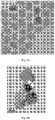
- TEM measurements were conducted as illustrated in Figs. 2A-2E .
- Samples for TEM analysis were prepared by drop casting 5 ⁇ L toluene dispersions of Ti02-oligopeptide-CdSe onto a carbon-coated copper grid, followed by air drying. Prior to TEM measurements, the samples were kept in vacuum for 12 hours.
- TEM was performed on a Philips T12 transmission electron microscope operating at 120 kV and equipped with a TVIPS CCD digital camera.
- Fig. 2A shows a TEM image of CdSe nanoparticles
- Figs. 2B-2C show a TEM image of CdSe anchored to TiO 2 nanoparticles.
- Fig. 2D shows a TEM image of a FFT pattern obtained from regions marked as I ( Fig. 2C )
- Fig. 2F shows a TEM image of a FFT pattern obtained from region II ( Fig. 2D ).
- the FFT images confirm the crystalline structure of the particles used.
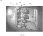
- Figs. 3A-3B present a cartoon of an example of a novel electrochemical cell 200 of the present invention which can be used for water splitting and a qualitative scheme of the energy levels involved in the excitation/oxidation process occurring at the electrode of the present invention respectively.
- TiO 2 particles 220 are attached to a fluorine-doped tin oxide (FTO- surface resistivity -7 Ohm/sq) conductive electrode 210.
- CdSe nanoparticles 130 are attached/bound to the TiO 2 nanoparticles 220 by various molecular linkers 160 including chiral ones.
- the H + ions are reduced to form H 2 .
- Fig. 3B illustrates a cell operation based on photoexcitation of the CdSe nanoparticles, while a potential is applied to the TiO 2 electrode in reference to the saturated Ag/AgCl electrode.
- the figure illustrates the electron transfer between the S -2 and the TiO 2 nanoparticles.
- excitation photoexcitation
- at least one excited electron is transferred from the CdSe nanoparticles through the chiral molecules to the TiO 2 electrode (from there to the external circuit), leaving a hole in the nanoparticle.
- Electrons produced (released) in the sulfur oxidation process are then transferred to the nanoparticle, and S 2 2 ⁇ is produced.
- the efficiency of the cell depends on the efficiency of electrons transfer from the photoexcited CdSe nanoparticles to the titania substrate.
- the molecules used as linkers between the nanoparticles and titania and their respective lengths are listed in Tables 1 and 2 above.
- This transfer is a spin-specific electron transfer, since the transfer through the chiral molecule is preferred for one spin over the other.
- the hole in the CdSe has a well-defined spin alignment, and therefore electrons with this spin will be transferred from the anions in the solution to CdSe.
- Fig. 4 presents the current density, as a function of the potential versus the Ag/AgCl electrode, using the novel electrode of the present invention coated with self-assembled monolayers of either achiral (dashed lines) or chiral (solid lines) molecules for the sake of comparison.
- the molecules related to each curve are written on the right axis.
- the experiments were performed in the dark.
- the scan was performed up to 1.5V to avoid oxidation of the molecules and destruction of the organic monolayer.
- the gradients of the currents obtained with the chiral molecules at 1.5 V are much larger than those observed with the achiral counterparts. All the achiral molecules are much shorter than the chiral ones and several of them are highly conjugated (see Table 2 ).
- the achiral molecules will conduct better and exhibit higher current.
- the opposite effect is observed and the chiral molecules have significantly lower threshold potentials for oxygen evolution, with a concomitant increase in the currents, than do the achiral molecules.
- the extreme case is the 13 nm-long DNA that exhibits high current despite being longer by about more than an order of magnitude than the MBA and MPA molecules.
- the current in the cells in which the anode is coated with chiral molecules is higher than for cells containing the achiral molecules.
- Figs. 5A-5B representing hydrogen production as function of time for two potentials (0.25V and 0.7V respectively) under illumination.
- Fig. 5A at 0.25 V only the novel electrode of the present invention made with the chiral polyalanine molecules produces hydrogen.
- hydrogen is produced only with the novel electrode of the present invention with chiral molecules.
- Fig. 5B the hydrogen production is measured on three cells at higher potential (0.7V).
- the rate of production is higher by about 30% for the novel cell of the present invention made with polyalanine as compared to that made of C3 alkyl chain.
- 0.7 V hydrogen is produced even when achiral molecules are used, but the rate of production is larger for the chiral molecules.
- the effect of the presence chiral molecules on the hydrogen production is clearly presented in Figs. 5A-5B .
- conductive probe AFM CP-AFM
- the spin polarization measured is 18 ⁇ 5%, 25 ⁇ 5% and 80 ⁇ 5% for the Al5, Al7, and DNA samples, respectively.
- the polarization is defined as the difference in the current of the two spins over the sum. This amounts to ratios in transmission between the two spins that are 1:1.4, 1:1.7, and 1:6, respectively.
- Self-assembled monolayers of oligopeptides were adsorbed on nickel substrates. Prior to the immobilization of the self-assembled monolayer, thin Ni films were thoroughly cleaned by placing them in boiling acetone and ethanol for 20 minutes each. Finally, the cleaned Ni samples were dipped in 0.1 mM solution of oligopeptide in dimethyl formamide for 24 hours.
- oligopeptides on the Ni surface was confirmed using polarization-modulated infrared absorption spectroscopy (PMIRRAS) and atomic force microscopy.
- PMIRRAS polarization-modulated infrared absorption spectroscopy
- Infrared absorption spectroscopy in reflection mode was carried out using a Nicolet 6700 FTIR, at an incidence angle of 80°, equipped with a PEM-90 photo elastic modulator (Hinds Instruments, Hillsboro, OR).
- Raw spectra were baseline-corrected by a spline algorithm.
- the PMIRRAS data represent two peaks located at 1660 and 1550 cm -1 .
- I-V spectroscopy measurements were recorded by performing voltage ramps with the tip in contact with the surface at an applied force of about 5 nN. Using the ramping software, the tip was lifted between spectroscopy points at different places on the surface. At least 25 I-V curves were averaged for each configuration (Magnet UP and Magnet DOWN) by leaving spectra that exhibit shorting and insulating behavior.
- the nanoshaving method is utilized to measure the thickness of the oligopeptide monolayer on the Ni surface.
- a defined area (1 ⁇ m x 1 ⁇ m) is scanned in contact mode by applying a large force on the AFM tip, which removes molecules present in that area due to their inherent flexibility of molecules, as shown in Fig. 6.
- Fig. 6 is an AFM topography of a monolayer of oligopeptide adsorbed on nickel. From the line profile, the thickness of the monolayer was found to be 2.8 ⁇ 0.2 nm.
- Figs. 7A-7B presenting hydrogen production as a function of time for the chiral molecules and for the achiral molecules respectively.
- the potentials in the brackets refer to the over-potential as defined in Table 2 above. The measurements were conducted at E app for each of the molecules. The effect of the chiral molecules on the hydrogen production is presented in these figures.
- At low effective over-potential ⁇ 0.5 V vs. Ag/AgCl
- hydrogen is produced only when the working electrode includes the chiral molecules.
- Fig. 7A shows that the over-potential is lower for the molecule with the higher spin selectivity, and thus the cell that includes DNA exhibits the lowest effective appearance potential.
- OCP open circuit potential
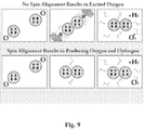
- Fig. 8 schematically presents the spin considerations related to oxygen/sulfur molecule formation from two oxygen/sulfur atoms in their triplet ground state.
- the energy scheme shown in Fig. 8 represents different mechanistic pathways for unpaired 80 and paired 82 photogenerated holes in the oxidation of water to oxygen and hydrogen.
- the atoms are in the ground state and each has a spin of 1 (triplet state) and their spins can be either aligned antiparallel 82 or parallel 80 to each other. If they are aligned parallel, they can form the triplet ground state of the oxygen molecule. However, if they are aligned antiparallel, their electronic state correlates with the excited singlet electronic state of the oxygen, which lies about 1 eV above the ground state. Hence, if they are on this singlet surface the formation of the oxygen ground state requires over-potential, since only when the two atoms are very close do their spins flip to form the molecular ground state. Therefore, to efficiently form hydrogen, the spins of the oxygen atoms must be pre-aligned, as indeed is the case when the electrodes are coated with chiral molecules.
- the distance between the oxygen atoms must be short, on the order of 0.1-0.2 nm, whereas if the spins are already aligned, the reaction can take place at a larger distance.
- some spin randomization occurs in the nanoparticle, owing to spin-orbit coupling.
- the rates of the electron transfer processes compete well with the spin relaxation time, which is in the order of picoseconds.
- Fig. 10 representing a gas chromatogram obtained from a pure hydrogen (commercial) sample injected into the gas chromatography chamber (curve a ) and from a gas sample produced in the photoelectrochemical cell, injected into the gas chromatography chamber (curve b ).
- the gas chromatography chamber was equipped with a thermal conductivity detector (TCD) and a GowMac instrument was used with a 20' ⁇ 1/8" stainless steel column packed with a molecular sieve (5 ⁇ ) in series with a 4' ⁇ 1/8" stainless steel column packed with HayeSep T.
- the curves were displaced relative to each other to facilitate the comparison.
- the peak at 1.57 min relates to all heavy gases present in the sample, whereas the peak at 4.91 min corresponds to hydrogen.
- the gas produced at 0.25 V versus Ag/AgCl in an electrochemical cell was collected using a Hamilton syringe and injected into a gas chromatography column. As shown in Fig. 10 , it is clear that the gas produced at the Pt electrode in the photoelectrochemical cell is hydrogen.
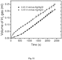
- Fig. 11 presents the hydrogen production as a function of time for two over-potentials, when the electrode used contained the long oligopeptide SHCH 2 CH 2 CO-(Ala-Aib) 7 -COOH at 0.25 and 0.40 V versus Ag/AgCl.
- the yield here is lower than with the shorter oligopeptide, hydrogen is produced at over-potential as low as 0.25.
Landscapes
- Chemical & Material Sciences (AREA)
- Engineering & Computer Science (AREA)
- Materials Engineering (AREA)
- Chemical Kinetics & Catalysis (AREA)
- Electrochemistry (AREA)
- Metallurgy (AREA)
- Organic Chemistry (AREA)
- Power Engineering (AREA)
- Inorganic Chemistry (AREA)
- Microelectronics & Electronic Packaging (AREA)
- Electrolytic Production Of Non-Metals, Compounds, Apparatuses Therefor (AREA)
- Electrodes For Compound Or Non-Metal Manufacture (AREA)
Claims (16)
- Système de craquage de l'eau, comprenant :
une cellule électrochimique (150), ladite cellule comprenant :une électrode (100) comprenant un substrat (102) possédant une surface électroconductrice portant un système chiral (104), conçue pour être immergée dans un électrolyte aqueux ;une contre-électrode (120) conçue pour être immergée dans le même électrolyte ; etun moyen pour appliquer une différence de potentiel entre ladite électrode (100) et ladite contre-électrode (120) ; etledit système de craquage de l'eau étant conçu pour appliquer une différence de potentiel à ladite cellule (150) de façon à créer des électrons et des trous d'électrons entraînant l'oxydation de l'eau et le transfert d'électrons entre le substrat et l'électrolyte aqueux,ledit système chiral (104) entraînant l'alignement du spin des électrons transférés durant de ladite oxydation de façon à réduire le surpotentiel du processus d'oxydation. - Système selon la revendication 1, ledit système chiral (104) comprenant au moins l'un des éléments suivants : des molécules chirales, un polymère chiral et de la matière organique et inorganique possédant des propriétés chirales.
- Système selon la revendication 1 ou 2, ledit système chiral (104) étant conçu sous la forme d'une structure monocouche ou multicouche.
- Système selon la revendication 3, ledit système chiral (104) comprenant une monocouche auto-assemblée des molécules chirales.
- Système selon l'une quelconque des revendications précédentes, ledit système chiral (104) comprenant au moins l'un des éléments suivants : des oligopeptides, des acides aminés, de l'ADN, des hélicènes et un polymère conducteur chiral.
- Système selon l'une quelconque des revendications précédentes, ledit système chiral (104) étant lié chimiquement à ladite surface du substrat (102) ou physiquement adsorbé sur celui-ci.
- Système selon l'une quelconque des revendications précédentes, ledit substrat (102) étant constitué d'au moins un métal ou un semi-conducteur.
- Système selon l'une quelconque des revendications précédentes, ladite électrode (100) étant conçue en tant que photo-absorbeur.
- Système selon la revendication 8, ledit substrat (102) étant conçu en tant que photo-absorbeur.
- Système selon la revendication 8 ou 9, ladite électrode (100) comprenant au moins l'un des éléments suivants : au moins une couche de photo-absorbeur portée par le substrat (102), et des nanoparticules photo-absorbantes liées au substrat (102) par l'intermédiaire dudit système chiral (104).
- Système selon l'une quelconque des revendications 8 à 10, ledit système chiral (104) comprenant au moins une couche de photo-absorbeur possédant des propriétés chirales.
- Système selon l'une quelconque des revendications précédentes, ladite électrode (100) étant une électrode d'anode, et ladite contre-électrode (120) étant une électrode de cathode et pouvant être raccordée à l'électrode d'anode, lesdits ions H+ étant transférés de l'électrode d'anode à l'électrode de cathode à travers l'électrolyte aqueux et lesdits électrons étant transférés de l'électrode d'anode à l'électrode de cathode par l'intermédiaire d'un circuit externe ; ladite électrode de cathode servant à, et étant conçue pour, entraîner une réduction des ions hydrogène par les électrons pour ainsi produire de l'hydrogène.
- Procédé de craquage de l'eau, comprenant :
la fourniture d'une cellule électrochimique (150), ladite cellule comprenant :une électrode (100) comprenant un substrat (102) possédant une surface électroconductrice portant un système chiral (104), conçue pour être immergée dans un électrolyte aqueux ;une contre-électrode (120) conçue pour être immergée dans le même électrolyte aqueux ; etun moyen pour appliquer une différence de potentiel entre ladite électrode (100) et ladite contre-électrode (120) ;l'immersion de l'électrode (100) et de la contre-électrode (120) dans un électrolyte aqueux ;l'application d'une différence de potentiel entre ladite électrode (100) et ladite contre-électrode (120) de façon à créer des électrons et des trous d'électrons entraînant l'oxydation de l'eau et le transfert d'électrons entre le substrat et l'électrolyte aqueux, ledit système chiral (104) entraînant l'alignement du spin des électrons transférés durant ladite oxydation de façon à réduire le surpotentiel du processus d'oxydation. - Procédé selon la revendication 13, ladite commande de ladite cellule (150) comprenant : l'excitation d'une électrode d'anode aboutissant à la formation d'électrons et de trous d'électrons entraînant l'oxydation de l'eau au niveau de l'électrode d'anode par des trous et l'alignement des spins d'électrons par le système chiral au niveau l'électrode d'anode.
- Procédé selon la revendication 14, ladite anode étant conçue en tant que photo-absorbeur, et ladite excitation étant une excitation induite par la lumière.
- Procédé selon l'une quelconque des revendications 13 à 15, ladite fourniture de la cellule électrochimique (150) comprenant l'application d'une différence de potentiel entre les électrodes d'anode et de cathode ; le transport d'ions H+ de l'électrode d'anode vers une électrode de cathode à travers un électrolyte aqueux et le transport d'électrons de l'électrode d'anode vers l'électrode de cathode à travers un circuit externe ; et la réduction des ions hydrogène au niveau de l'électrode de cathode par des électrons pour ainsi produire de l'hydrogène.
Applications Claiming Priority (2)
| Application Number | Priority Date | Filing Date | Title |
|---|---|---|---|
| US201462060590P | 2014-10-07 | 2014-10-07 | |
| PCT/IL2015/051004 WO2016056011A1 (fr) | 2014-10-07 | 2015-10-07 | Système et procédé de décomposition de l'eau |
Publications (3)
| Publication Number | Publication Date |
|---|---|
| EP3204533A1 EP3204533A1 (fr) | 2017-08-16 |
| EP3204533A4 EP3204533A4 (fr) | 2018-05-02 |
| EP3204533B1 true EP3204533B1 (fr) | 2020-09-16 |
Family
ID=55652691
Family Applications (1)
| Application Number | Title | Priority Date | Filing Date |
|---|---|---|---|
| EP15849585.3A Active EP3204533B1 (fr) | 2014-10-07 | 2015-10-07 | Système et procédé de décomposition de l'eau |
Country Status (5)
| Country | Link |
|---|---|
| US (2) | US10519554B2 (fr) |
| EP (1) | EP3204533B1 (fr) |
| CN (1) | CN106795637B (fr) |
| CA (1) | CA2962758A1 (fr) |
| WO (1) | WO2016056011A1 (fr) |
Families Citing this family (4)
| Publication number | Priority date | Publication date | Assignee | Title |
|---|---|---|---|---|
| JP7280590B2 (ja) * | 2016-01-28 | 2023-05-24 | ロズウェル バイオテクノロジーズ,インコーポレイテッド | 大スケールの分子電子工学センサアレイを使用する被分析物を測定するための方法および装置 |
| WO2017221250A1 (fr) * | 2016-06-23 | 2017-12-28 | Yeda Research And Development Co. Ltd. | Système et procédé destinés à être utilisés dans l'analyse de molécules chirales |
| EP3480341B1 (fr) * | 2017-11-07 | 2021-12-01 | INDIAN OIL CORPORATION Ltd. | Dissociation photoélectrochimique de l'eau |
| WO2023228196A1 (fr) * | 2022-05-26 | 2023-11-30 | Chiral Ltd | Procédé de commande d'une fonction de travail d'au moins une surface, électrode, dispositif de stockage d'énergie de cellule électrochimique, cellule photovoltaïque et composant électrique associé |
Family Cites Families (6)
| Publication number | Priority date | Publication date | Assignee | Title |
|---|---|---|---|---|
| EP0849378A1 (fr) * | 1996-12-17 | 1998-06-24 | Tosoh Corporation | Cathode présentant une faible surtension d'hydrogène et son procédé de fabrication |
| JPH1112776A (ja) * | 1997-06-25 | 1999-01-19 | Asahi Glass Co Ltd | 修飾電極および該修飾電極を用いた電解酸化方法 |
| CN102421942B (zh) * | 2009-06-02 | 2014-04-16 | 松下电器产业株式会社 | 光电化学单元 |
| JP5324501B2 (ja) * | 2010-03-09 | 2013-10-23 | 国立大学法人信州大学 | 電気化学用電極とその製造方法 |
| WO2013005252A1 (fr) * | 2011-07-06 | 2013-01-10 | 株式会社 日立製作所 | Electrode pour électrolyse, son procédé de fabrication et appareil d'électrolyse |
| US9737880B2 (en) * | 2012-03-28 | 2017-08-22 | Emory University | Photocatalytic polyoxometalate compositions of tungstovanadates and uses as water oxidation catalysts |
-
2015
- 2015-10-07 WO PCT/IL2015/051004 patent/WO2016056011A1/fr active Application Filing
- 2015-10-07 CA CA2962758A patent/CA2962758A1/fr not_active Abandoned
- 2015-10-07 EP EP15849585.3A patent/EP3204533B1/fr active Active
- 2015-10-07 US US15/517,738 patent/US10519554B2/en active Active
- 2015-10-07 CN CN201580053553.6A patent/CN106795637B/zh not_active Expired - Fee Related
-
2019
- 2019-11-15 US US16/684,889 patent/US20200080207A1/en not_active Abandoned
Non-Patent Citations (1)
| Title |
|---|
| None * |
Also Published As
| Publication number | Publication date |
|---|---|
| US10519554B2 (en) | 2019-12-31 |
| EP3204533A4 (fr) | 2018-05-02 |
| EP3204533A1 (fr) | 2017-08-16 |
| CN106795637A (zh) | 2017-05-31 |
| CN106795637B (zh) | 2020-03-20 |
| WO2016056011A1 (fr) | 2016-04-14 |
| US20180030601A1 (en) | 2018-02-01 |
| CA2962758A1 (fr) | 2016-04-14 |
| US20200080207A1 (en) | 2020-03-12 |
Similar Documents
| Publication | Publication Date | Title |
|---|---|---|
| US20200080207A1 (en) | Water splitting method and system | |
| Huang et al. | Amorphous NiWO4 nanoparticles boosting the alkaline hydrogen evolution performance of Ni3S2 electrocatalysts | |
| Kecsenovity et al. | Decoration of ultra-long carbon nanotubes with Cu 2 O nanocrystals: a hybrid platform for enhanced photoelectrochemical CO 2 reduction | |
| Shi et al. | Carbon coated Cu2O nanowires for photo-electrochemical water splitting with enhanced activity | |
| Liu et al. | Gold nanocluster sensitized TiO 2 nanotube arrays for visible-light driven photoelectrocatalytic removal of antibiotic tetracycline | |
| Balasubramanian et al. | Electrochemically functionalized carbon nanotubes for device applications | |
| Sawaguchi et al. | Electrochemical scanning tunneling microscopy and ultrahigh-vacuum investigation of gold cyanide adlayers on Au (111) formed in aqueous solution | |
| Hu et al. | Rational design of electrocatalysts for simultaneously promoting bulk charge separation and surface charge transfer in solar water splitting photoelectrodes | |
| CN102482076B (zh) | 新型结构的碳纳米复合体及其制造方法 | |
| Seo et al. | A molecular approach to an electrocatalytic hydrogen evolution reaction on single-layer graphene | |
| US10505201B2 (en) | CNT sheet substrates and transition metals deposited on same | |
| Aryanrad et al. | Europium oxide nanorod-reduced graphene oxide nanocomposites towards supercapacitors | |
| Xu et al. | Chemical vapor deposition of amorphous molybdenum sulphide on black phosphorus for photoelectrochemical water splitting | |
| Janáky et al. | On the substantially improved photoelectrochemical properties of nanoporous WO 3 through surface decoration with RuO 2 | |
| JP5401666B2 (ja) | 窒素固定化材料及びその製造方法並びに窒素固定化方法 | |
| Abramo et al. | Electrocatalytic production of glycolic acid via oxalic acid reduction on titania debris supported on a TiO2 nanotube array | |
| CN115092994B (zh) | 一种含有电子穿梭体的电容去离子复合电极去除水中磷酸根离子的方法 | |
| Xiao et al. | Nanostructured electrode with titania nanotube arrays: fabrication, electrochemical properties, and applications for biosensing | |
| WO2019119044A1 (fr) | Catalyseurs d'oxydation d'eau biomimétiques | |
| JP2017125242A (ja) | 還元反応用電極及びそれを用いた反応デバイス | |
| KR102167758B1 (ko) | 이산화 티타늄 나노구조체를 이용한 염소발생 전극 및 이의 제조방법 | |
| Colby et al. | Biotemplated synthesis of metallic nanoparticle chains on an α-synuclein fiber scaffold | |
| CN114250472A (zh) | 一种BiVO4/CoP薄膜电极及其制备方法和应用 | |
| Bardavid et al. | Conducting polymer coated DNA | |
| CN103323510A (zh) | 一种基于芳基重氮盐功能化金纳米粒子的修饰电极的制备方法 |
Legal Events
| Date | Code | Title | Description |
|---|---|---|---|
| STAA | Information on the status of an ep patent application or granted ep patent |
Free format text: STATUS: THE INTERNATIONAL PUBLICATION HAS BEEN MADE |
|
| PUAI | Public reference made under article 153(3) epc to a published international application that has entered the european phase |
Free format text: ORIGINAL CODE: 0009012 |
|
| STAA | Information on the status of an ep patent application or granted ep patent |
Free format text: STATUS: REQUEST FOR EXAMINATION WAS MADE |
|
| 17P | Request for examination filed |
Effective date: 20170424 |
|
| AK | Designated contracting states |
Kind code of ref document: A1 Designated state(s): AL AT BE BG CH CY CZ DE DK EE ES FI FR GB GR HR HU IE IS IT LI LT LU LV MC MK MT NL NO PL PT RO RS SE SI SK SM TR |
|
| AX | Request for extension of the european patent |
Extension state: BA ME |
|
| DAV | Request for validation of the european patent (deleted) | ||
| DAX | Request for extension of the european patent (deleted) | ||
| A4 | Supplementary search report drawn up and despatched |
Effective date: 20180404 |
|
| RIC1 | Information provided on ipc code assigned before grant |
Ipc: C25B 11/04 20060101ALI20180327BHEP Ipc: H01G 9/20 20060101ALI20180327BHEP Ipc: C25B 1/00 20060101ALI20180327BHEP Ipc: C25B 1/04 20060101AFI20180327BHEP |
|
| STAA | Information on the status of an ep patent application or granted ep patent |
Free format text: STATUS: EXAMINATION IS IN PROGRESS |
|
| 17Q | First examination report despatched |
Effective date: 20190214 |
|
| GRAP | Despatch of communication of intention to grant a patent |
Free format text: ORIGINAL CODE: EPIDOSNIGR1 |
|
| STAA | Information on the status of an ep patent application or granted ep patent |
Free format text: STATUS: GRANT OF PATENT IS INTENDED |
|
| INTG | Intention to grant announced |
Effective date: 20200529 |
|
| GRAS | Grant fee paid |
Free format text: ORIGINAL CODE: EPIDOSNIGR3 |
|
| GRAA | (expected) grant |
Free format text: ORIGINAL CODE: 0009210 |
|
| STAA | Information on the status of an ep patent application or granted ep patent |
Free format text: STATUS: THE PATENT HAS BEEN GRANTED |
|
| AK | Designated contracting states |
Kind code of ref document: B1 Designated state(s): AL AT BE BG CH CY CZ DE DK EE ES FI FR GB GR HR HU IE IS IT LI LT LU LV MC MK MT NL NO PL PT RO RS SE SI SK SM TR |
|
| REG | Reference to a national code |
Ref country code: GB Ref legal event code: FG4D |
|
| REG | Reference to a national code |
Ref country code: CH Ref legal event code: EP |
|
| REG | Reference to a national code |
Ref country code: DE Ref legal event code: R096 Ref document number: 602015059305 Country of ref document: DE |
|
| REG | Reference to a national code |
Ref country code: IE Ref legal event code: FG4D |
|
| REG | Reference to a national code |
Ref country code: CH Ref legal event code: NV Representative=s name: SERVOPATENT GMBH, CH Ref country code: AT Ref legal event code: REF Ref document number: 1314248 Country of ref document: AT Kind code of ref document: T Effective date: 20201015 |
|
| PG25 | Lapsed in a contracting state [announced via postgrant information from national office to epo] |
Ref country code: SE Free format text: LAPSE BECAUSE OF FAILURE TO SUBMIT A TRANSLATION OF THE DESCRIPTION OR TO PAY THE FEE WITHIN THE PRESCRIBED TIME-LIMIT Effective date: 20200916 Ref country code: NO Free format text: LAPSE BECAUSE OF FAILURE TO SUBMIT A TRANSLATION OF THE DESCRIPTION OR TO PAY THE FEE WITHIN THE PRESCRIBED TIME-LIMIT Effective date: 20201216 Ref country code: BG Free format text: LAPSE BECAUSE OF FAILURE TO SUBMIT A TRANSLATION OF THE DESCRIPTION OR TO PAY THE FEE WITHIN THE PRESCRIBED TIME-LIMIT Effective date: 20201216 Ref country code: GR Free format text: LAPSE BECAUSE OF FAILURE TO SUBMIT A TRANSLATION OF THE DESCRIPTION OR TO PAY THE FEE WITHIN THE PRESCRIBED TIME-LIMIT Effective date: 20201217 Ref country code: FI Free format text: LAPSE BECAUSE OF FAILURE TO SUBMIT A TRANSLATION OF THE DESCRIPTION OR TO PAY THE FEE WITHIN THE PRESCRIBED TIME-LIMIT Effective date: 20200916 Ref country code: HR Free format text: LAPSE BECAUSE OF FAILURE TO SUBMIT A TRANSLATION OF THE DESCRIPTION OR TO PAY THE FEE WITHIN THE PRESCRIBED TIME-LIMIT Effective date: 20200916 |
|
| REG | Reference to a national code |
Ref country code: AT Ref legal event code: MK05 Ref document number: 1314248 Country of ref document: AT Kind code of ref document: T Effective date: 20200916 |
|
| REG | Reference to a national code |
Ref country code: NL Ref legal event code: MP Effective date: 20200916 |
|
| PG25 | Lapsed in a contracting state [announced via postgrant information from national office to epo] |
Ref country code: RS Free format text: LAPSE BECAUSE OF FAILURE TO SUBMIT A TRANSLATION OF THE DESCRIPTION OR TO PAY THE FEE WITHIN THE PRESCRIBED TIME-LIMIT Effective date: 20200916 Ref country code: LV Free format text: LAPSE BECAUSE OF FAILURE TO SUBMIT A TRANSLATION OF THE DESCRIPTION OR TO PAY THE FEE WITHIN THE PRESCRIBED TIME-LIMIT Effective date: 20200916 |
|
| REG | Reference to a national code |
Ref country code: LT Ref legal event code: MG4D |
|
| PG25 | Lapsed in a contracting state [announced via postgrant information from national office to epo] |
Ref country code: CZ Free format text: LAPSE BECAUSE OF FAILURE TO SUBMIT A TRANSLATION OF THE DESCRIPTION OR TO PAY THE FEE WITHIN THE PRESCRIBED TIME-LIMIT Effective date: 20200916 Ref country code: EE Free format text: LAPSE BECAUSE OF FAILURE TO SUBMIT A TRANSLATION OF THE DESCRIPTION OR TO PAY THE FEE WITHIN THE PRESCRIBED TIME-LIMIT Effective date: 20200916 Ref country code: SM Free format text: LAPSE BECAUSE OF FAILURE TO SUBMIT A TRANSLATION OF THE DESCRIPTION OR TO PAY THE FEE WITHIN THE PRESCRIBED TIME-LIMIT Effective date: 20200916 Ref country code: PT Free format text: LAPSE BECAUSE OF FAILURE TO SUBMIT A TRANSLATION OF THE DESCRIPTION OR TO PAY THE FEE WITHIN THE PRESCRIBED TIME-LIMIT Effective date: 20210118 Ref country code: RO Free format text: LAPSE BECAUSE OF FAILURE TO SUBMIT A TRANSLATION OF THE DESCRIPTION OR TO PAY THE FEE WITHIN THE PRESCRIBED TIME-LIMIT Effective date: 20200916 Ref country code: LT Free format text: LAPSE BECAUSE OF FAILURE TO SUBMIT A TRANSLATION OF THE DESCRIPTION OR TO PAY THE FEE WITHIN THE PRESCRIBED TIME-LIMIT Effective date: 20200916 |
|
| PG25 | Lapsed in a contracting state [announced via postgrant information from national office to epo] |
Ref country code: ES Free format text: LAPSE BECAUSE OF FAILURE TO SUBMIT A TRANSLATION OF THE DESCRIPTION OR TO PAY THE FEE WITHIN THE PRESCRIBED TIME-LIMIT Effective date: 20200916 Ref country code: AT Free format text: LAPSE BECAUSE OF FAILURE TO SUBMIT A TRANSLATION OF THE DESCRIPTION OR TO PAY THE FEE WITHIN THE PRESCRIBED TIME-LIMIT Effective date: 20200916 Ref country code: AL Free format text: LAPSE BECAUSE OF FAILURE TO SUBMIT A TRANSLATION OF THE DESCRIPTION OR TO PAY THE FEE WITHIN THE PRESCRIBED TIME-LIMIT Effective date: 20200916 Ref country code: PL Free format text: LAPSE BECAUSE OF FAILURE TO SUBMIT A TRANSLATION OF THE DESCRIPTION OR TO PAY THE FEE WITHIN THE PRESCRIBED TIME-LIMIT Effective date: 20200916 Ref country code: IS Free format text: LAPSE BECAUSE OF FAILURE TO SUBMIT A TRANSLATION OF THE DESCRIPTION OR TO PAY THE FEE WITHIN THE PRESCRIBED TIME-LIMIT Effective date: 20210116 |
|
| REG | Reference to a national code |
Ref country code: DE Ref legal event code: R097 Ref document number: 602015059305 Country of ref document: DE |
|
| PG25 | Lapsed in a contracting state [announced via postgrant information from national office to epo] |
Ref country code: SK Free format text: LAPSE BECAUSE OF FAILURE TO SUBMIT A TRANSLATION OF THE DESCRIPTION OR TO PAY THE FEE WITHIN THE PRESCRIBED TIME-LIMIT Effective date: 20200916 Ref country code: LU Free format text: LAPSE BECAUSE OF NON-PAYMENT OF DUE FEES Effective date: 20201007 Ref country code: MC Free format text: LAPSE BECAUSE OF FAILURE TO SUBMIT A TRANSLATION OF THE DESCRIPTION OR TO PAY THE FEE WITHIN THE PRESCRIBED TIME-LIMIT Effective date: 20200916 |
|
| REG | Reference to a national code |
Ref country code: BE Ref legal event code: MM Effective date: 20201031 |
|
| PLBE | No opposition filed within time limit |
Free format text: ORIGINAL CODE: 0009261 |
|
| STAA | Information on the status of an ep patent application or granted ep patent |
Free format text: STATUS: NO OPPOSITION FILED WITHIN TIME LIMIT |
|
| 26N | No opposition filed |
Effective date: 20210617 |
|
| GBPC | Gb: european patent ceased through non-payment of renewal fee |
Effective date: 20201216 |
|
| PG25 | Lapsed in a contracting state [announced via postgrant information from national office to epo] |
Ref country code: SI Free format text: LAPSE BECAUSE OF FAILURE TO SUBMIT A TRANSLATION OF THE DESCRIPTION OR TO PAY THE FEE WITHIN THE PRESCRIBED TIME-LIMIT Effective date: 20200916 Ref country code: DK Free format text: LAPSE BECAUSE OF FAILURE TO SUBMIT A TRANSLATION OF THE DESCRIPTION OR TO PAY THE FEE WITHIN THE PRESCRIBED TIME-LIMIT Effective date: 20200916 Ref country code: BE Free format text: LAPSE BECAUSE OF NON-PAYMENT OF DUE FEES Effective date: 20201031 |
|
| PG25 | Lapsed in a contracting state [announced via postgrant information from national office to epo] |
Ref country code: IE Free format text: LAPSE BECAUSE OF NON-PAYMENT OF DUE FEES Effective date: 20201007 Ref country code: IT Free format text: LAPSE BECAUSE OF FAILURE TO SUBMIT A TRANSLATION OF THE DESCRIPTION OR TO PAY THE FEE WITHIN THE PRESCRIBED TIME-LIMIT Effective date: 20200916 |
|
| PG25 | Lapsed in a contracting state [announced via postgrant information from national office to epo] |
Ref country code: GB Free format text: LAPSE BECAUSE OF NON-PAYMENT OF DUE FEES Effective date: 20201216 |
|
| PG25 | Lapsed in a contracting state [announced via postgrant information from national office to epo] |
Ref country code: IS Free format text: LAPSE BECAUSE OF FAILURE TO SUBMIT A TRANSLATION OF THE DESCRIPTION OR TO PAY THE FEE WITHIN THE PRESCRIBED TIME-LIMIT Effective date: 20210116 Ref country code: TR Free format text: LAPSE BECAUSE OF FAILURE TO SUBMIT A TRANSLATION OF THE DESCRIPTION OR TO PAY THE FEE WITHIN THE PRESCRIBED TIME-LIMIT Effective date: 20200916 Ref country code: MT Free format text: LAPSE BECAUSE OF FAILURE TO SUBMIT A TRANSLATION OF THE DESCRIPTION OR TO PAY THE FEE WITHIN THE PRESCRIBED TIME-LIMIT Effective date: 20200916 Ref country code: CY Free format text: LAPSE BECAUSE OF FAILURE TO SUBMIT A TRANSLATION OF THE DESCRIPTION OR TO PAY THE FEE WITHIN THE PRESCRIBED TIME-LIMIT Effective date: 20200916 |
|
| PG25 | Lapsed in a contracting state [announced via postgrant information from national office to epo] |
Ref country code: MK Free format text: LAPSE BECAUSE OF FAILURE TO SUBMIT A TRANSLATION OF THE DESCRIPTION OR TO PAY THE FEE WITHIN THE PRESCRIBED TIME-LIMIT Effective date: 20200916 |
|
| PG25 | Lapsed in a contracting state [announced via postgrant information from national office to epo] |
Ref country code: NL Free format text: LAPSE BECAUSE OF NON-PAYMENT OF DUE FEES Effective date: 20200923 |
|
| P01 | Opt-out of the competence of the unified patent court (upc) registered |
Effective date: 20230722 |
|
| PGFP | Annual fee paid to national office [announced via postgrant information from national office to epo] |
Ref country code: FR Payment date: 20231009 Year of fee payment: 9 Ref country code: DE Payment date: 20231003 Year of fee payment: 9 Ref country code: CH Payment date: 20231102 Year of fee payment: 9 |