EP3203244B1 - Trigger on final occurrence - Google Patents
Trigger on final occurrence Download PDFInfo
- Publication number
- EP3203244B1 EP3203244B1 EP17154703.7A EP17154703A EP3203244B1 EP 3203244 B1 EP3203244 B1 EP 3203244B1 EP 17154703 A EP17154703 A EP 17154703A EP 3203244 B1 EP3203244 B1 EP 3203244B1
- Authority
- EP
- European Patent Office
- Prior art keywords
- event
- events
- series
- trigger
- signal
- Prior art date
- Legal status (The legal status is an assumption and is not a legal conclusion. Google has not performed a legal analysis and makes no representation as to the accuracy of the status listed.)
- Active
Links
Images

Classifications
-
- G—PHYSICS
- G01—MEASURING; TESTING
- G01R—MEASURING ELECTRIC VARIABLES; MEASURING MAGNETIC VARIABLES
- G01R13/00—Arrangements for displaying electric variables or waveforms
- G01R13/02—Arrangements for displaying electric variables or waveforms for displaying measured electric variables in digital form
- G01R13/0218—Circuits therefor
- G01R13/0254—Circuits therefor for triggering, synchronisation
-
- G—PHYSICS
- G01—MEASURING; TESTING
- G01R—MEASURING ELECTRIC VARIABLES; MEASURING MAGNETIC VARIABLES
- G01R13/00—Arrangements for displaying electric variables or waveforms
- G01R13/02—Arrangements for displaying electric variables or waveforms for displaying measured electric variables in digital form
- G01R13/0218—Circuits therefor
- G01R13/0245—Circuits therefor for inserting reference markers
Definitions
- This disclosure relates generally to test and measurement instruments such as digital oscilloscopes and more particularly, to triggering modes in such instruments.
- Embodiments of the invention address these and other limitations of the prior art.
- Document US 2010/0228508 A1 discloses a test and measurement apparatus, system, and method for synchronizing an acquisition or triggering system to a specific burst of interest.
- Embodiments of the invention are directed to triggering on the final occurrence of an event.
- Triggering Fundamentals reference it is known to trigger on a new event - for example, if a signal on a particular input channel of an oscilloscope changes from HIGH to LOW, or when an input signal crosses a pre-set threshold level.
- the trigger event need not necessarily be based on data that is being received by the input channel of the oscilloscope, but instead may be from a different source, such as a time period expiring, or other external event.
- the trigger event can cause many things to happen in or on the scope, such as stopping data from the input channel being stored in an acquisition memory after a certain post-trigger delay from the triggering event and subsequently being displayed, analyzed, stored to non-volatile memory, etc.
- FIG. 1 is an example waveform diagram that shows a simplified example of the trigger on final occurrence in a test instrument such as an oscilloscope.
- a series of wide pulses 104A - 104D as well as a number of narrow pulses 102 in a waveform 100.
- the oscilloscope is trying to determine which of the wide pulses 104 in the waveform 100 is the final occurrence of the wide pulse.
- a timer helps determine the final occurrence of the wide pulse 104.
- a repetition period 106A is the time between wide pulse 104A and 104B.
- a next repetition period 106B follows the wide pulse 104B, etc.
- Each repetition period 106 has a maximum duration, which may be measured by a timer (not illustrated, but very common on oscilloscopes).
- One way to determine that the last wide pulse 104D is the final occurrence in the waveform 100 is to set a timer to timeout at the maximum duration of the repetition period 106. If the event has not repeated by the end of the timeout period, then the last event previously received by the oscilloscope is determined to be the last in the series. This determination may be used to stop data storage in the acquisition memory and initiate display, analysis, non-volatile storage, etc. In the illustrated example, a timeout period 108 exceeds the maximum length of the repetition period 106. Therefore, the oscilloscope determines, since no wide pulse 104 occurred within the timeout period following 106C, that the wide pulse 104D is the last or final occurrence of wide pulses 104 in the waveform 100.
- the determination is made at the time reference 110, which is determined by adding the timeout period 108 to the end of the last repetition period 106C.
- the last wide pulse 104 is the wide pulse that occurred before the timeout period 108, which, as illustrated, is the wide pulse 104D.
- the timeout period 108 may be determined in a number of ways. For example, it may be pre-set if the maximum duration of the repetition period 106 is known. It may also be automatically calculated by measuring an average number of repetition periods, then adding a timeout margin. For example, if the average repetition period 106 is empirically determined to be 15 ⁇ s, then a timeout period 108 could be set at 17 ⁇ s, 20 ⁇ s, or any other time longer than 15 ⁇ s, for instance, depending on how tight of a tolerance to the average repetition period was desired. The timeout period may also be set as just above the maximum duration of a number of repetition periods observed during a testing period.
- a timeout period could be set at 90 ms.
- other methods of setting a timeout period are also possible, and embodiments of the invention may work with any of such methods.
- the oscilloscope determines the trigger location, for example, the trigger location 115 for the waveform 100.
- the trigger location within an acquired record may be determined by subtracting the post-trigger delay from the end of the acquired record.
- One method of determining a trigger location of the final occurrence is to subtract the timeout period 108 from the point in time, 110, where the timeout occurred and the acquisition ended.
- the acquisition memory may be storing the waveform data 100 as it is being provided to the oscilloscope, but, since there is only a finite amount of acquisition memory available, the oldest waveform data 100 is overwritten by the new data as the waveform 100 continues.
- the circular buffer is sized to capture a desired amount of data both before and after the trigger event, and the post-trigger delay is set to continue acquisition for just the duration of the desired data after the trigger event.
- Embodiments of the invention size the circular buffer to continue storing data during the timeout period without overwriting the desired pre-trigger data, then after the trigger point is established, effectively "retrieve" the information previously stored in the acquisition buffer that would have been overwritten had the circular buffer size not been increased.
- embodiments of the invention calculate what data from the acquisition buffer needs to be saved, and mark such data surrounding the calculated final occurrence time as data of interest to the trigger. In some contexts, this marking of the data of interest is known as timestamping, or generating a timestamp in the data acquisition memory. In the example illustrated in Fig. 1 , assume that the waveform 100 is being acquired and saved in acquisition memory.
- the oscilloscope marks or timestamps already-acquired data in the acquisition memory as being important, beginning before the trigger location 115 by the desired pre-trigger time. More details of this operation appear below. Including a very accurate timeout timer, such as a crystal controlled clock in the oscilloscope, gives a very accurate location to the trigger point determined using the process above. If the timeout timer is not extremely accurate, additional data prior to a calculated trigger point may be included as part of the timestamped triggered data to ensure that important data is not lost from the acquisition memory.
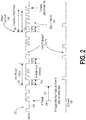
- Fig. 2 illustrates a more complex method of determining a trigger based on a final occurrence of an event.
- the example illustrated in Fig. 1 involved only a single factor, i.e., a timeout
- the example in Fig. 2 illustrates a two-stage determination.
- the example diagram in FIG. 2 represents a training sequence used to establish data communication speed for 100Gbps Ethernet.
- Data that is of interest by a user is illustrated generally as Data of Interest 142.
- Embodiments of the invention allow such data of interest 142 to be isolated in a straightforward manner, while presently it is very difficult to isolate such data.
- the protocol of this Ethernet training signal 120 includes a first initialization stage followed by a repetitive training stage.
- the initialization signal in the training signal 120 is an analog signal.
- various inputs may be used for triggers.
- the training signal 120 is first analyzed for an initialization signal 122, which is considered an "A" trigger.
- the initialization signal 122 is received, indicated by the long pulse after the initialization stage, the A trigger is satisfied, and the oscilloscope begins evaluating the training signal 120 for a "B" trigger.
- the B trigger is a final B event in a series of B events, similar to the timeout example described above.
- a unique starting point 126 is established at the A trigger, which, in turn, enables the B trigger.
- the starting point 126 begins a period during which the oscilloscope determines a final occurrence of a "B" event in the training data signal 120.
- using the B trigger-after-delay-by-time enables the oscilloscope to effectively discard or skip a portion 128 of the training signal 120, by not capturing (or at least not keeping, i.e., by overwriting in the acquisition memory buffer) the training data signal 120 during the portion 128 between the A and B triggers, and the unimportant periods of repetition during B events 150.
- This configuration of triggers allows a B trigger to be set up to find a header of control data that is repeated during the training sequence for the 100Gbps Ethernet setup, the last incidence of which is the section of data of interest 142 to the user.
- the B trigger is in a Pulse Width mode, which searches for relatively long pulses 130 to indicate B events 150.
- a "B" event 150 is indicated in Fig. 2 as the wide pulse 130 in the training signal 120.
- B events 150 are also illustrated as isolated pulses near the bottom of Fig. 2 .
- the B events 150 repeat approximately every 100 ⁇ s, which is used as the repetition period 124.
- a first B event 150 occurs at the conclusion of the time period indicated as 130A, while a second B event occurs just after the time period 130B. Then many B events 150 repeat, as indicated by the dotted lines in the training signal 120 and B events graph 150.
- the B event 150 may repeat hundreds or thousands of times, which illustrates why embodiments of the invention, which effectively skip over the repeated events to select the final event, is very useful. The B events 150 continue until the final B event illustrated at the conclusion of time period 130Y.
- a timeout circuit measures the amount of time following each time period 130, and determines a timeout 140 occurs only when the training signal 120 progressed longer than the timeout period after a B event 150.
- the timeout period is illustrated as 134, while the repetition period is illustrated as 124.
- a timing circuit determines that the training signal 120 continued longer than the timeout period 134 without generating another B pulse.
- the timeout was determined to occur at point 140, and the B pulse 150 following the time period 130Y was determined to be the final occurrence of the B pulse.
- the proper trigger location 145 to capture the final B pulse 150 is determined by subtracting the timeout period 134 from where the timeout occurred at 140. Therefore, the trigger location is set as the beginning of the pulse 130Y, which is the correct location to reference as the trigger point when locating the data of interest 142 within the acquisition memory.
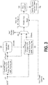
- Fig. 3 illustrates an example flow diagram illustrating how the training signal 120 of Fig. 2 may be evaluated using triggers according to embodiments of the invention.
- an input receives the training signal 120 and then an evaluation operation 162 determines whether Trigger A has occurred.
- Trigger A was a particular analog signal 122, but embodiments of the invention may use any type of Trigger as the Trigger A.
- Trigger A could be any trigger type, such as glitch, serial, runt, pulse-width, time-out, etc. or any other known type of trigger, or a final event trigger according to embodiments of the invention.
- a multiplexer 168 may be set to only evaluate the A trigger by changing the control input, and not consider the B trigger. In such an instance, the remainder of the flow continues as described in more detail below.
- a trigger state machine 166 upon receiving the A trigger from operation 162, enables the B trigger to be evaluated in a B trigger evaluation operation 164.
- the trigger state machine 166 may also switch the multiplexer 168 to evaluate for B events.
- the B trigger evaluation was a final B event, as described above. Embodiments of the invention may work with any type of trigger, however.
- an event timer 170 is set to time out at a particular time to determine when the last B event occurred. Or, if the system were set up to monitor a last A event, by enabling the multiplexer 168 to evaluate the A trigger, then the system illustrated in Fig. 3 could search a data stream for a last A event. No matter which "final event" the system illustrated in Fig. 3 is searching for, the event timer 170 monitors the system to determine if a timeout time has passed since the last B (or A, if selected by the multiplexer 168) event. If the B event recurs within the timeout period, then effectively nothing happens and no B trigger is triggered.
- the B trigger is satisfied, because a 'final' B event has occurred.
- the acquisition of data stops in an operation 180, meaning that new data is prevented from being stored in the acquisition memory of the oscilloscope, or at least a portion of the acquisition memory is marked to be saved.
- the time-out value is subtracted from the time of the timeout event, and a trigger timestamp is generated at the point of data in the acquisition memory where the last B event occurred. This was illustrated in Fig. 2 by subtracting the timeout period 134 from the determination of timeout 140, to mark the proper trigger location 145.
- the data of interest for example the data of interest 142 in Fig. 2 may be evaluated by the user.
- the event timer 170 may include more than a simple timeout.
- the event timer may be set to skip over intermediate time values between a pair of two time values, but determine a final event based on a time value outside the pair of two time values.
- the timer 170 may be set to trigger a final B event if no event occurred before a timeout, using a maximum timer, as described above.
- a minimum timer may also be employed to ensure that a (settable) time passes between two adjacent pulses. And, if two adjacent pulses occur within the minimum time, then either of the pulses may be selected as being the pulse of interest, and the appropriate timestamp generated to mark the acquisition data of interest.
- the event timer 170 may include any type of timer, such as count-down, count-up, interval, shift-register, analog ramp, or other type of timer.
- a force timeout signal 184 may operate in conjunction with the event timer 170 to provide additional control to the user.
- a force timeout 184 signal may be used to prevent the timeout timer in the event timer 170 from being reset on any new input events, and therefore forces the timer 170 to declare the final event that passed before the force timeout signal 184 was asserted to be the final event, regardless of whether additional events actually occur in the data after the force timeout signal 184 was asserted.
- the force timeout signal 184 may be asserted by the user in a situation where the user wishes to study a particular portion of the data stream. In such a configuration, where the force timeout 184 is used, the timestamp subtraction operation 182 still operates, and the data trigger timestamp in the acquisition memory is set to be the final event prior to assertion of the force timeout signal 184.
- the force timeout signal 184 may be used to immediately stop acquisition of data in the acquisition memory, because the user knows that the final occurrence has already been captured and stored in acquisition memory.
- the timestamp subtraction 182 may be omitted if temporary timestamps are generated for the acquisition memory as each event occurs. For example, with reference to Fig. 2 , if a final occurrence temporary timestamp was generated for each time a B event 150 occurred, then the force timeout signal could cause the oscilloscope to immediately mark the last-occurring temporary timestamp as the final occurrence timestamp, and the data surrounding such a timestamp as the data of interest.
- Fig. 2 is specifically for 100Gbps Ethernet Link training
- embodiments of the invention may be used in many situations where data of interest is near the last occurrence of an event.
- many data negotiation protocols used to set a channel speed include a designated start point followed by a pattern that repeats with a regular interval or until a reset event, and then has an end point.
- Embodiments of the invention may be used to search for the designated start point (as Trigger A), then use the trigger on final occurrence feature as Trigger B, to capture and select the data of interest.
- Trigger A the designated start point
- Trigger B the trigger on final occurrence feature
- an A-B sequence trigger may not be needed, so some embodiments may be set to evaluate an A trigger only, as illustrated in Fig. 1 .
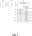
- FIG. 4 is a block diagram illustrating example components of a test and measurement system including a test and measurement instrument 400 coupled via a test probe 402 to a device under test (DUT) 404.
- the test and measurement instrument 400 may be an oscilloscope or other type of instrument.
- the test and measurement instrument includes a user interface 410, a processor 420 coupled to processor memory 422, and a display 430 coupled to display memory 432.
- the processor 420 may be programmed to operate based on instructions stored on the processor memory 422, which may be read only memory, random access memory, flash memory, codes stored on an FPGA or other reprogrammable circuit, or other forms of memory.
- the test and measurement instrument 400 includes input circuitry for receiving an input signal from the DUT 404 via the probe 402 and outputting a digital signal to the processor.
- the input signal is typically an analog signal but is converted to digital form by an analog-to-digital (A/D) converter 460 within the instrument 400.
- the processor 420 is operative to receive and process the digital signal and to output one or more signals derived therefrom.
- An acquisition memory 450 stores input signals from the DUT 404.
- the acquisition memory 450 may be configured as a circular buffer, which overwrites the oldest acquired signals with newer acquired signals on a rolling basis.
- a trigger subsystem 440 includes one or more trigger event decoders operative responsive to one or more features of the input signal or the digital signal, or based on other signals such as the force timeout signal 184 ( Fig. 3 ) to initiate or end an acquisition of the signal and to control storage of the digital signal in memory.
- the trigger subsystem may be configured to operate as illustrated in the flow of Fig. 3 , and may be configured to analyze an input signal as describe above with reference to Figs. 1 and 2 above.
- the trigger subsystem 440 may include a last event analyzer 422, which may operate as set forth above to generate a trigger signal when the last event of a series of events has occurred in the input signal.
- a trigger timestamp calculator determines which data already stored in the acquisition memory 450 is marked as data of interest.
- the last event analyzer 442 may initiate other processes, such as enabling other triggers to be set as an active trigger by the test and measurement system 400.
- the last event analyzer 442 or other functions in the trigger subsystem 440 may initiate or end an acquisition following a programmed period of time after the last occurrence of a trigger event.
- the timestamp calculator 452 is then operative to position the digital signal stored in the acquisition memory according to the time of occurrence of the last trigger event.
Description
- This disclosure relates generally to test and measurement instruments such as digital oscilloscopes and more particularly, to triggering modes in such instruments.
- In recent years, several high speed serial data communication standards, such as PCIe and Ethernet, have defined a set of initiating sequences between nodes on a data channel to optimize a maximum speed of communication over the data channel. These initiation or training sequences have a defined protocol with a definite starting point but a widely variable duration, which is largely dependent on the amount of attenuation in the serial channel. For 100Gbps Ethernet, the training sequence can range in duration from 200ms to 500ms. Users have a desire to be able to determine the results of a final action in the training sequence, e.g. to determine the final results of the agreed protocol, but there is no present way to directly capture such results.
- Despite the very long data record lengths used in present oscilloscopes, when initiating high speed data channels, the scope is often unable to fully capture the complete training sequence. Even if the data acquisition memory in the scope could store a long enough record to capture the entire training sequence, the amount of time required to process such a large record is many minutes, and would negatively impact the throughput of the instrument. Therefore, a software search for the final sequence also does not satisfy needs of the users, due to the long delay in processing such a long record.
- Embodiments of the invention address these and other limitations of the prior art.
- Document
US 2010/0228508 A1 discloses a test and measurement apparatus, system, and method for synchronizing an acquisition or triggering system to a specific burst of interest. - Embodiments of the invention are set out in the appended claims.
-
-
FIG. 1 is an example of generating a trigger on a final occurrence of a repeating pattern according to embodiments of the invention. -
FIG. 2 is an example diagram of a training sequence illustrating how embodiments of the invention may be used in conjunction with multiple triggers. -
FIG. 3 is a signal flow diagram of an example implementation of the trigger on final occurrence according to embodiments of the invention. -
FIG. 4 is a block diagram of an example of a test and measurement system in which one embodiment of the trigger on final occurrence is implemented. - A variety of known triggering techniques are described in "Triggering Fundamentals" www.Tektronix.com/oscilloscopes, Copyright 2011 Tektronix.
- Embodiments of the invention are directed to triggering on the final occurrence of an event. As described in the Triggering Fundamentals reference, it is known to trigger on a new event - for example, if a signal on a particular input channel of an oscilloscope changes from HIGH to LOW, or when an input signal crosses a pre-set threshold level. Also, the trigger event need not necessarily be based on data that is being received by the input channel of the oscilloscope, but instead may be from a different source, such as a time period expiring, or other external event. The trigger event can cause many things to happen in or on the scope, such as stopping data from the input channel being stored in an acquisition memory after a certain post-trigger delay from the triggering event and subsequently being displayed, analyzed, stored to non-volatile memory, etc.
- There is sometimes a need, however, to capture data related to a "final" occurrence of an event in a series of events. In present oscilloscopes, there is no way to distinguish the input data related to a final occurrence of an event. Embodiments of the invention, conversely, purposely continue storing data in the acquisition memory after each event and then, after the final trigger event occurs, mark a certain location in the previously stored data as the beginning of the data of interest. Many details and variations of this concept are set forth in detail below.
- To trigger on the "final" occurrence of an event presumes that there are non-final events that may be ignored. For instance, if a particular data pattern repeats eight times, the first seven times the pattern repeats are non-final events, while the eighth repetition is the final occurrence. This may be relatively easy to track when the number of recurrences is known, but it is much more difficult to ascertain the final occurrence when the number of recurrences is unknown, or more difficult still, variable. Therefore, embodiments of the invention use a number of different methods and techniques to determine when a particular occurrence of an event is a final occurrence. Then, after the final occurrence is identified, data about the final occurrence may be retrieved and analyzed, for instance.
-
FIG. 1 is an example waveform diagram that shows a simplified example of the trigger on final occurrence in a test instrument such as an oscilloscope. - In this example there are a series of
wide pulses 104A - 104D as well as a number ofnarrow pulses 102 in awaveform 100. The oscilloscope is trying to determine which of the wide pulses 104 in thewaveform 100 is the final occurrence of the wide pulse. In this example, a timer helps determine the final occurrence of the wide pulse 104. With reference to thewaveform 100, there is a repetition period 106 that follows each wide pulse 104. For example, arepetition period 106A is the time betweenwide pulse next repetition period 106B follows thewide pulse 104B, etc. Each repetition period 106 has a maximum duration, which may be measured by a timer (not illustrated, but very common on oscilloscopes). One way to determine that the last wide pulse 104D is the final occurrence in thewaveform 100 is to set a timer to timeout at the maximum duration of the repetition period 106. If the event has not repeated by the end of the timeout period, then the last event previously received by the oscilloscope is determined to be the last in the series. This determination may be used to stop data storage in the acquisition memory and initiate display, analysis, non-volatile storage, etc. In the illustrated example, atimeout period 108 exceeds the maximum length of the repetition period 106. Therefore, the oscilloscope determines, since no wide pulse 104 occurred within the timeout period following 106C, that the wide pulse 104D is the last or final occurrence of wide pulses 104 in thewaveform 100. In this example, the determination is made at thetime reference 110, which is determined by adding thetimeout period 108 to the end of thelast repetition period 106C. Thus, the last wide pulse 104 is the wide pulse that occurred before thetimeout period 108, which, as illustrated, is the wide pulse 104D. - The
timeout period 108 may be determined in a number of ways. For example, it may be pre-set if the maximum duration of the repetition period 106 is known. It may also be automatically calculated by measuring an average number of repetition periods, then adding a timeout margin. For example, if the average repetition period 106 is empirically determined to be 15 µs, then atimeout period 108 could be set at 17 µs, 20 µs, or any other time longer than 15 µs, for instance, depending on how tight of a tolerance to the average repetition period was desired. The timeout period may also be set as just above the maximum duration of a number of repetition periods observed during a testing period. For example, if after a sampling period the maximum repetition period was determined to be 88 ms, then a timeout period could be set at 90 ms. Of course, other methods of setting a timeout period are also possible, and embodiments of the invention may work with any of such methods. - After the final occurrence of the repeated event has been determined, the oscilloscope determines the trigger location, for example, the
trigger location 115 for thewaveform 100. In prior-art trigger operation, the trigger location within an acquired record may be determined by subtracting the post-trigger delay from the end of the acquired record. However, since the final occurrence of a trigger event may not be determined at the time of occurrence, a different method is required. One method of determining a trigger location of the final occurrence is to subtract thetimeout period 108 from the point in time, 110, where the timeout occurred and the acquisition ended. Thus, subtracting thetimeout period 108 from thetimeout point 110 gives thetrigger location 115 at the falling edge of the last wide pulse 104D (the time at which 104D is identified as a wide pulse, but well before it could be determined to be the final wide pulse). Data about thewaveform 100, or thewaveform 100 itself, is stored in an acquisition memory of the oscilloscope beginning before thetrigger location 115. In practice, the data about thewaveform 100 may have already been stored in the acquisition memory, which is set to operate as a circular buffer. In other words, prior to a triggering event, the acquisition memory may be storing thewaveform data 100 as it is being provided to the oscilloscope, but, since there is only a finite amount of acquisition memory available, theoldest waveform data 100 is overwritten by the new data as thewaveform 100 continues. Normally, the circular buffer is sized to capture a desired amount of data both before and after the trigger event, and the post-trigger delay is set to continue acquisition for just the duration of the desired data after the trigger event. Embodiments of the invention, however, size the circular buffer to continue storing data during the timeout period without overwriting the desired pre-trigger data, then after the trigger point is established, effectively "retrieve" the information previously stored in the acquisition buffer that would have been overwritten had the circular buffer size not been increased. In other words, embodiments of the invention calculate what data from the acquisition buffer needs to be saved, and mark such data surrounding the calculated final occurrence time as data of interest to the trigger. In some contexts, this marking of the data of interest is known as timestamping, or generating a timestamp in the data acquisition memory. In the example illustrated inFig. 1 , assume that thewaveform 100 is being acquired and saved in acquisition memory. Until the trigger is tripped, none of the data in the acquisition memory is marked as being important or needing to be saved. After thetimeout point 110, the oscilloscope then marks or timestamps already-acquired data in the acquisition memory as being important, beginning before thetrigger location 115 by the desired pre-trigger time. More details of this operation appear below. Including a very accurate timeout timer, such as a crystal controlled clock in the oscilloscope, gives a very accurate location to the trigger point determined using the process above. If the timeout timer is not extremely accurate, additional data prior to a calculated trigger point may be included as part of the timestamped triggered data to ensure that important data is not lost from the acquisition memory. -
Fig. 2 illustrates a more complex method of determining a trigger based on a final occurrence of an event. Whereas the example illustrated inFig. 1 involved only a single factor, i.e., a timeout, the example inFig. 2 illustrates a two-stage determination. In particular, the example diagram inFIG. 2 represents a training sequence used to establish data communication speed for 100Gbps Ethernet. Data that is of interest by a user is illustrated generally as Data ofInterest 142. Embodiments of the invention allow such data ofinterest 142 to be isolated in a straightforward manner, while presently it is very difficult to isolate such data. - The protocol of this
Ethernet training signal 120 includes a first initialization stage followed by a repetitive training stage. Ordinarily, but not essentially, the initialization signal in thetraining signal 120 is an analog signal. As described above, various inputs may be used for triggers. For the 100G Ethernet standard, thetraining signal 120 is first analyzed for aninitialization signal 122, which is considered an "A" trigger. After theinitialization signal 122 is received, indicated by the long pulse after the initialization stage, the A trigger is satisfied, and the oscilloscope begins evaluating thetraining signal 120 for a "B" trigger. In this example, the B trigger is a final B event in a series of B events, similar to the timeout example described above. In the Example illustrated inFig. 2 , aunique starting point 126 is established at the A trigger, which, in turn, enables the B trigger. Thestarting point 126 begins a period during which the oscilloscope determines a final occurrence of a "B" event in the training data signal 120. Although there may be a substantial period of time following thestarting point 126, using the B trigger-after-delay-by-time enables the oscilloscope to effectively discard or skip aportion 128 of thetraining signal 120, by not capturing (or at least not keeping, i.e., by overwriting in the acquisition memory buffer) the training data signal 120 during theportion 128 between the A and B triggers, and the unimportant periods of repetition duringB events 150. This configuration of triggers allows a B trigger to be set up to find a header of control data that is repeated during the training sequence for the 100Gbps Ethernet setup, the last incidence of which is the section of data ofinterest 142 to the user. - In this example, the B trigger is in a Pulse Width mode, which searches for relatively long pulses 130 to indicate
B events 150. A "B"event 150 is indicated inFig. 2 as the wide pulse 130 in thetraining signal 120.B events 150 are also illustrated as isolated pulses near the bottom ofFig. 2 . TheB events 150 repeat approximately every 100 µs, which is used as the repetition period 124. InFig. 2 , afirst B event 150 occurs at the conclusion of the time period indicated as 130A, while a second B event occurs just after thetime period 130B. Thenmany B events 150 repeat, as indicated by the dotted lines in thetraining signal 120 andB events graph 150. In real test cases, theB event 150 may repeat hundreds or thousands of times, which illustrates why embodiments of the invention, which effectively skip over the repeated events to select the final event, is very useful. TheB events 150 continue until the final B event illustrated at the conclusion of time period 130Y. - A timeout circuit measures the amount of time following each time period 130, and determines a
timeout 140 occurs only when thetraining signal 120 progressed longer than the timeout period after aB event 150. In other words, with reference toFig. 2 , the timeout period is illustrated as 134, while the repetition period is illustrated as 124. Beginning at the pulse 130Y, a timing circuit determines that thetraining signal 120 continued longer than thetimeout period 134 without generating another B pulse. Thus, the timeout was determined to occur atpoint 140, and theB pulse 150 following the time period 130Y was determined to be the final occurrence of the B pulse. Then, as described above, theproper trigger location 145 to capture thefinal B pulse 150 is determined by subtracting thetimeout period 134 from where the timeout occurred at 140. Therefore, the trigger location is set as the beginning of the pulse 130Y, which is the correct location to reference as the trigger point when locating the data ofinterest 142 within the acquisition memory. -
Fig. 3 illustrates an example flow diagram illustrating how thetraining signal 120 ofFig. 2 may be evaluated using triggers according to embodiments of the invention. With reference toFigs. 2 andFig. 3 , an input receives thetraining signal 120 and then anevaluation operation 162 determines whether Trigger A has occurred. InFig. 2 , Trigger A was aparticular analog signal 122, but embodiments of the invention may use any type of Trigger as the Trigger A. For example, Trigger A could be any trigger type, such as glitch, serial, runt, pulse-width, time-out, etc. or any other known type of trigger, or a final event trigger according to embodiments of the invention. - If the A trigger is the only trigger in the system being evaluated, a
multiplexer 168 may be set to only evaluate the A trigger by changing the control input, and not consider the B trigger. In such an instance, the remainder of the flow continues as described in more detail below. - If instead of merely evaluating an A trigger, both an A trigger and a B trigger are being considered, then a
trigger state machine 166, upon receiving the A trigger fromoperation 162, enables the B trigger to be evaluated in a Btrigger evaluation operation 164. Thetrigger state machine 166 may also switch themultiplexer 168 to evaluate for B events. InFigure 2 , the B trigger evaluation was a final B event, as described above. Embodiments of the invention may work with any type of trigger, however. - As described with reference to
Fig. 2 , anevent timer 170 is set to time out at a particular time to determine when the last B event occurred. Or, if the system were set up to monitor a last A event, by enabling themultiplexer 168 to evaluate the A trigger, then the system illustrated inFig. 3 could search a data stream for a last A event. No matter which "final event" the system illustrated inFig. 3 is searching for, theevent timer 170 monitors the system to determine if a timeout time has passed since the last B (or A, if selected by the multiplexer 168) event. If the B event recurs within the timeout period, then effectively nothing happens and no B trigger is triggered. If instead no B event occurs within the timeout period, then the B trigger is satisfied, because a 'final' B event has occurred. When the B trigger is satisfied, the acquisition of data stops in anoperation 180, meaning that new data is prevented from being stored in the acquisition memory of the oscilloscope, or at least a portion of the acquisition memory is marked to be saved. Then, in anoperation 182, the time-out value is subtracted from the time of the timeout event, and a trigger timestamp is generated at the point of data in the acquisition memory where the last B event occurred. This was illustrated inFig. 2 by subtracting thetimeout period 134 from the determination oftimeout 140, to mark theproper trigger location 145. Then the data of interest, for example the data ofinterest 142 inFig. 2 may be evaluated by the user. - In some embodiments, the
event timer 170 may include more than a simple timeout. For example, in some embodiments, the event timer may be set to skip over intermediate time values between a pair of two time values, but determine a final event based on a time value outside the pair of two time values. For example, thetimer 170 may be set to trigger a final B event if no event occurred before a timeout, using a maximum timer, as described above. A minimum timer may also be employed to ensure that a (settable) time passes between two adjacent pulses. And, if two adjacent pulses occur within the minimum time, then either of the pulses may be selected as being the pulse of interest, and the appropriate timestamp generated to mark the acquisition data of interest. - The
event timer 170 may include any type of timer, such as count-down, count-up, interval, shift-register, analog ramp, or other type of timer. - Along the same lines, a
force timeout signal 184 may operate in conjunction with theevent timer 170 to provide additional control to the user. For example, aforce timeout 184 signal may be used to prevent the timeout timer in theevent timer 170 from being reset on any new input events, and therefore forces thetimer 170 to declare the final event that passed before theforce timeout signal 184 was asserted to be the final event, regardless of whether additional events actually occur in the data after theforce timeout signal 184 was asserted. Theforce timeout signal 184 may be asserted by the user in a situation where the user wishes to study a particular portion of the data stream. In such a configuration, where theforce timeout 184 is used, thetimestamp subtraction operation 182 still operates, and the data trigger timestamp in the acquisition memory is set to be the final event prior to assertion of theforce timeout signal 184. - In another mode, the
force timeout signal 184 may be used to immediately stop acquisition of data in the acquisition memory, because the user knows that the final occurrence has already been captured and stored in acquisition memory. In this embodiment, thetimestamp subtraction 182 may be omitted if temporary timestamps are generated for the acquisition memory as each event occurs. For example, with reference toFig. 2 , if a final occurrence temporary timestamp was generated for each time aB event 150 occurred, then the force timeout signal could cause the oscilloscope to immediately mark the last-occurring temporary timestamp as the final occurrence timestamp, and the data surrounding such a timestamp as the data of interest. - Although the Example shown in
Fig. 2 is specifically for 100Gbps Ethernet Link training, embodiments of the invention may be used in many situations where data of interest is near the last occurrence of an event. For example, many data negotiation protocols used to set a channel speed include a designated start point followed by a pattern that repeats with a regular interval or until a reset event, and then has an end point. Embodiments of the invention may be used to search for the designated start point (as Trigger A), then use the trigger on final occurrence feature as Trigger B, to capture and select the data of interest. For some patterns or sequences, an A-B sequence trigger may not be needed, so some embodiments may be set to evaluate an A trigger only, as illustrated inFig. 1 . -
FIG. 4 is a block diagram illustrating example components of a test and measurement system including a test andmeasurement instrument 400 coupled via atest probe 402 to a device under test (DUT) 404. The test andmeasurement instrument 400 may be an oscilloscope or other type of instrument. The test and measurement instrument includes auser interface 410, aprocessor 420 coupled toprocessor memory 422, and adisplay 430 coupled todisplay memory 432. Theprocessor 420 may be programmed to operate based on instructions stored on theprocessor memory 422, which may be read only memory, random access memory, flash memory, codes stored on an FPGA or other reprogrammable circuit, or other forms of memory. - The test and
measurement instrument 400 includes input circuitry for receiving an input signal from theDUT 404 via theprobe 402 and outputting a digital signal to the processor. The input signal is typically an analog signal but is converted to digital form by an analog-to-digital (A/D)converter 460 within theinstrument 400. Theprocessor 420 is operative to receive and process the digital signal and to output one or more signals derived therefrom. - An
acquisition memory 450 stores input signals from theDUT 404. As described above, theacquisition memory 450 may be configured as a circular buffer, which overwrites the oldest acquired signals with newer acquired signals on a rolling basis. - A
trigger subsystem 440 includes one or more trigger event decoders operative responsive to one or more features of the input signal or the digital signal, or based on other signals such as the force timeout signal 184 (Fig. 3 ) to initiate or end an acquisition of the signal and to control storage of the digital signal in memory. The trigger subsystem may be configured to operate as illustrated in the flow ofFig. 3 , and may be configured to analyze an input signal as describe above with reference toFigs. 1 and2 above. Thetrigger subsystem 440 may include alast event analyzer 422, which may operate as set forth above to generate a trigger signal when the last event of a series of events has occurred in the input signal. Based on such a last event trigger from thelast event analyzer 422, or based on other triggering events, a trigger timestamp calculator determines which data already stored in theacquisition memory 450 is marked as data of interest. In other embodiments thelast event analyzer 442 may initiate other processes, such as enabling other triggers to be set as an active trigger by the test andmeasurement system 400. In yet other embodiments thelast event analyzer 442 or other functions in thetrigger subsystem 440 may initiate or end an acquisition following a programmed period of time after the last occurrence of a trigger event. Thetimestamp calculator 452 is then operative to position the digital signal stored in the acquisition memory according to the time of occurrence of the last trigger event.
Claims (14)
- A test and measurement instrument comprising:an input circuit for receiving an input signal;an acquisition memory (450) structured to store a digital signal related to the input signal; anda trigger (440) subsystem having:one or more event decoders operative responsive to one or more features of the input signal or the digital signal to detect that a series of events occurred;the test and measurement instrument is characterised bya timer structured to detect that a last previously detected event in the series of events is a final event in the series of events based on passage of a timeout period after the last previously detected event; anda last event analyzer (442) structured to generate a trigger signal in response to detecting that the final event in the series of events occurred.
- The test and measurement instrument according to claim 1, in which the timer begins timing when an event in the series of events is detected, and in which generating the trigger signal is suppressed when an event in the series of events is detected before the timeout period expires; optionally
wherein the timer is reset when an event in the series of events is detected. - The test and measurement system according to claims 1 or 2, in which the timer is crystal controlled.
- The test and measurement instrument according to any preceding claim, further comprising a timestamp indicator structured to indicate a timestamp associated to a particular portion of the digital signal stored in the acquisition memory when the trigger signal is generated; optionally
wherein the timestamp is associated to a portion of the data related to the final event in the series of events. - The test and measurement instrument according to claim 4, in which the timestamp is generated by subtracting the timeout period from a time when a timeout was determined to have occurred; and/or
wherein the timestamp indicator locates an approximate location of the final event in the stored digital signal, and further comprising a correction facility structured to analyze the stored digital signal to determine a specific location of the final event in the stored digital signal. - The test and measurement instrument according to any preceding claim, in which the trigger (440) subsystem includes an input structured to receive a forced timeout signal, and in which, when the forced timeout signal is received, the trigger subsystem indicates the final event in the series of events is the event most recently received before the forced timeout signal was received.
- The test and measurement instrument according to any preceding claim, in which the digital signal stored in the acquisition memory (450) is marked with a temporary timestamp at detected events in the series of events.
- The test and measurement instrument according to any preceding claim, in which the trigger (440) subsystem is structured to detect a first triggering event in the input signal or the digital signal before enabling the detection of the series of events.
- A processor controlled method of generating a trigger in a test and measurement instrument, the method comprising:receiving an input signal;digitizing the input signal into a digital signal;storing the digital signal in an acquisition memory (450);evaluating the input signal or the digital signal for events in a series of events;the method is characterised bydetecting that a last previously detected event in the series of events is a final event in the series of events based on passage of a timeout period after the last previously detected event; andgenerating the trigger in response to the final event in the series of events being detected.
- The method according to claim 9, wherein the timer is a crystal controlled timer.
- The method according to claim 9 or 10, further comprising:indicating a timestamp in relation to the acquisition memory (450) when the final event in the series of events occurs; and optionally;refining a location of the timestamp by evaluating data stored in the acquisition memory (450).
- The method according to claim 10, further comprising:
generating a timestamp in the acquisition memory (450) by subtracting a period of time stored in the timer from a point in time when the final event in the series of events was detected. - The method according to any of claims 9 to 12, further comprising receiving a forced timeout signal, and in which an event of the series of events received prior to receiving the forced timeout signal is deemed to be the final event in the series of events.
- The method according to any of claims 9 to 13, in which the series of events are not evaluated for a final event until another event occurs, the other event unrelated to the series of events.
Applications Claiming Priority (2)
| Application Number | Priority Date | Filing Date | Title |
|---|---|---|---|
| US201662292085P | 2016-02-05 | 2016-02-05 | |
| US15/395,593 US10365300B2 (en) | 2016-02-05 | 2016-12-30 | Trigger on final occurrence |
Publications (2)
| Publication Number | Publication Date |
|---|---|
| EP3203244A1 EP3203244A1 (en) | 2017-08-09 |
| EP3203244B1 true EP3203244B1 (en) | 2020-11-04 |
Family
ID=58265752
Family Applications (1)
| Application Number | Title | Priority Date | Filing Date |
|---|---|---|---|
| EP17154703.7A Active EP3203244B1 (en) | 2016-02-05 | 2017-02-03 | Trigger on final occurrence |
Country Status (4)
| Country | Link |
|---|---|
| US (1) | US10365300B2 (en) |
| EP (1) | EP3203244B1 (en) |
| JP (1) | JP7291998B2 (en) |
| CN (1) | CN107290578B (en) |
Families Citing this family (8)
| Publication number | Priority date | Publication date | Assignee | Title |
|---|---|---|---|---|
| US10416203B2 (en) * | 2017-03-31 | 2019-09-17 | Rohde & Schwarz Gmbh & Co. Kg | Test and measurement system, differential logic probe, single ended logic probe and method for operating a test and measurement system |
| US11609246B2 (en) * | 2017-05-18 | 2023-03-21 | Rohde & Schwarz Gmbh & Co. Kg | Test and measurement device as well as method for applying a trigger |
| DE102018221534A1 (en) * | 2017-12-18 | 2019-06-19 | Robert Bosch Engineering And Business Solutions Private Limited | System and method for measuring the response time of event strings |
| US11307061B2 (en) * | 2018-03-08 | 2022-04-19 | Rohde & Schwarz Gmbh & Co. Kg | Electrical measurement device |
| US10641820B1 (en) * | 2018-10-19 | 2020-05-05 | Teradyne, Inc. | Automated test equipment with relay hot-switch detection |
| CN110763888B (en) * | 2019-11-15 | 2021-12-07 | 北京普源精电科技有限公司 | Method and device for automatically identifying trigger type and oscilloscope |
| KR20230007469A (en) * | 2020-07-21 | 2023-01-12 | 주식회사 아도반테스토 | Automatic test equipment and method using trigger generation |
| WO2023078572A1 (en) * | 2021-11-08 | 2023-05-11 | Advantest Corporation | Automated test equipment, device under test, test setup methods using a trigger line |
Family Cites Families (35)
| Publication number | Priority date | Publication date | Assignee | Title |
|---|---|---|---|---|
| DE2951677C2 (en) * | 1979-12-21 | 1982-08-05 | Fa. Dipl.-Ing. Bruno Richter, 8602 Stegaurach | Method and device for generating a trigger signal |
| JPS57194362A (en) * | 1981-05-26 | 1982-11-29 | Iwatsu Electric Co Ltd | Observing device for signal |
| US4755887A (en) * | 1986-10-31 | 1988-07-05 | Hewlett-Packard Company | Triggering for waveform recording |
| JPS63277975A (en) * | 1987-04-30 | 1988-11-15 | Yokogawa Hewlett Packard Ltd | Trigger event capturing device |
| US5067130A (en) * | 1989-09-29 | 1991-11-19 | Tektronix, Inc. | Method for acquiring data in a logic analyzer |
| JPH0627149A (en) * | 1992-07-09 | 1994-02-04 | Meidensha Corp | Triggering method for logic analyzer |
| JP2003344455A (en) * | 2002-05-24 | 2003-12-03 | Yokogawa Electric Corp | Waveform measuring device |
| US7398175B2 (en) * | 2002-12-18 | 2008-07-08 | Tektronix, Inc. | Method and apparatus providing multiple channel multiple instrument triggering |
| US7191079B2 (en) * | 2004-03-23 | 2007-03-13 | Tektronix, Inc. | Oscilloscope having advanced triggering capability |
| US20070200550A1 (en) * | 2006-02-28 | 2007-08-30 | Corredoura Paul L | Trigger architecture, measurement system and method of use |
| US7558936B2 (en) * | 2006-03-24 | 2009-07-07 | Tektronix, Inc. | Data management in long record length memory |
| US7352167B2 (en) * | 2006-03-24 | 2008-04-01 | Tektronix, Inc. | Digital trigger |
| GB2455052A (en) * | 2007-09-21 | 2009-06-03 | Agilent Technologies Inc | Trigger event detection apparatus and method therefore |
| US8046183B2 (en) * | 2008-03-04 | 2011-10-25 | Tektronix, Inc. | Pre-trigger and post-trigger acquisition for no dead time acquisition system |
| US8161497B2 (en) * | 2008-03-26 | 2012-04-17 | Tektronix, Inc. | Holdoff algorithm for no dead time acquisition |
| CN101281224B (en) * | 2008-04-18 | 2011-06-01 | 电子科技大学 | Method for testing digital oscilloscope waveform capturing rate |
| US9075696B2 (en) | 2009-03-09 | 2015-07-07 | Tektronix, Inc. | Apparatus and method for performing burst triggering in a test and measurement instrument |
| US8024141B2 (en) * | 2009-09-04 | 2011-09-20 | Tektronix, Inc. | Test and measurement instrument and method for providing post-acquisition trigger control and presentation |
| US20110060540A1 (en) * | 2009-09-04 | 2011-03-10 | Tektronix, Inc. | Test and Measurement Instrument and Method For Providing Post-Acquisition Trigger Control and Presentation |
| CN102053189B (en) * | 2009-11-10 | 2016-08-10 | 北京普源精电科技有限公司 | A kind of digital oscilloscope with sequence Trigger Function and control method thereof |
| US9069017B2 (en) | 2009-12-04 | 2015-06-30 | Tektronix, Inc. | Serial bit stream regular expression engine |
| US8374811B2 (en) * | 2009-12-07 | 2013-02-12 | Tektronix, Inc. | High waveform throughput with a large acquisition memory |
| US20120001657A1 (en) * | 2010-06-30 | 2012-01-05 | Tektronix, Inc. | Apparatus and method for improved edge triggering in a test and measurement instrument |
| US8446308B2 (en) * | 2011-04-21 | 2013-05-21 | Kabushiki Kaisha Toshiba | Apparatus for detection of a leading edge of a photo sensor output signal |
| CN102788892B (en) * | 2011-05-18 | 2016-09-07 | 北京普源精电科技有限公司 | A kind of digital oscilloscope for accurately triggering |
| CN103018512B (en) * | 2011-09-23 | 2016-09-07 | 北京普源精电科技有限公司 | A kind of oscillograph with external trigger function |
| US9291646B2 (en) * | 2012-07-27 | 2016-03-22 | Tektronix, Inc. | Cross domain triggering in a test and measurement instrument |
| US9541579B2 (en) * | 2012-09-25 | 2017-01-10 | Tektronix, Inc. | Methods and systems for generating displays of waveforms |
| CN103809001A (en) * | 2012-11-09 | 2014-05-21 | 江苏绿扬电子仪器集团有限公司 | Digital phosphor oscilloscope pretrigger device |
| US10235339B2 (en) * | 2013-02-19 | 2019-03-19 | Keysight Technologies, Inc. | Digital measurement instrument triggered by signal pattern |
| US9571156B2 (en) * | 2013-03-14 | 2017-02-14 | Cisco Technology, Inc. | Burst triggered signal analysis |
| CN103308738B (en) * | 2013-05-10 | 2015-05-13 | 电子科技大学 | Abnormal waveform recording method for oscilloscope with high capture rate |
| US10094868B2 (en) * | 2014-04-11 | 2018-10-09 | Tektronix, Inc. | Test and measurement instrument having advanced triggering capability |
| US9344301B2 (en) * | 2014-05-30 | 2016-05-17 | Guzik Technical Enterprises | Acquisition device with multistage digital equalization |
| US9268321B2 (en) * | 2014-06-24 | 2016-02-23 | Keysight Technologies, Inc. | Digital tiggering using finite state machines |
-
2016
- 2016-12-30 US US15/395,593 patent/US10365300B2/en active Active
-
2017
- 2017-02-03 EP EP17154703.7A patent/EP3203244B1/en active Active
- 2017-02-06 JP JP2017019836A patent/JP7291998B2/en active Active
- 2017-02-06 CN CN201710065456.XA patent/CN107290578B/en active Active
Non-Patent Citations (1)
| Title |
|---|
| None * |
Also Published As
| Publication number | Publication date |
|---|---|
| CN107290578A (en) | 2017-10-24 |
| US10365300B2 (en) | 2019-07-30 |
| JP2017201295A (en) | 2017-11-09 |
| EP3203244A1 (en) | 2017-08-09 |
| CN107290578B (en) | 2024-03-22 |
| US20170227581A1 (en) | 2017-08-10 |
| JP7291998B2 (en) | 2023-06-16 |
Similar Documents
| Publication | Publication Date | Title |
|---|---|---|
| EP3203244B1 (en) | Trigger on final occurrence | |
| US6609077B1 (en) | ATE timing measurement unit and method | |
| US7191079B2 (en) | Oscilloscope having advanced triggering capability | |
| CN104977448B (en) | Test and measurement instrument with advanced triggering capability | |
| JP2733746B2 (en) | Logic signal display method | |
| JP6460623B2 (en) | Test measurement device, trigger setting method thereof, and program for test measurement device | |
| EP1306998A3 (en) | Method and apparatus for performing eye diagram measurements | |
| US9759747B2 (en) | Method and a device for determining a trigger condition for a rare signal event | |
| US20120001657A1 (en) | Apparatus and method for improved edge triggering in a test and measurement instrument | |
| US9874587B1 (en) | One-pass trigger jitter reduction for digital instruments | |
| JP7237477B2 (en) | Test and measurement system and method therefor | |
| EP0515028A1 (en) | Automatic anomalous event detection | |
| US5731984A (en) | Vector-based waveform acquisition and display | |
| CN104849549A (en) | Method and system for measuring impulse frequency | |
| US7265700B2 (en) | Method and apparatus for extracting individual pulses from an input signal | |
| US8255188B2 (en) | Fast low frequency jitter rejection methodology | |
| CN112051425A (en) | Mode acquisition in an equivalent time sampling system | |
| JP2009503458A (en) | Method and system for digital triggering of a signal based on two trigger events separated by a time interval | |
| JPH02151773A (en) | Logic analyzer | |
| JPS60242388A (en) | Measuring device for time margin |
Legal Events
| Date | Code | Title | Description |
|---|---|---|---|
| PUAI | Public reference made under article 153(3) epc to a published international application that has entered the european phase |
Free format text: ORIGINAL CODE: 0009012 |
|
| STAA | Information on the status of an ep patent application or granted ep patent |
Free format text: STATUS: THE APPLICATION HAS BEEN PUBLISHED |
|
| AK | Designated contracting states |
Kind code of ref document: A1 Designated state(s): AL AT BE BG CH CY CZ DE DK EE ES FI FR GB GR HR HU IE IS IT LI LT LU LV MC MK MT NL NO PL PT RO RS SE SI SK SM TR |
|
| AX | Request for extension of the european patent |
Extension state: BA ME |
|
| STAA | Information on the status of an ep patent application or granted ep patent |
Free format text: STATUS: REQUEST FOR EXAMINATION WAS MADE |
|
| 17P | Request for examination filed |
Effective date: 20180209 |
|
| RBV | Designated contracting states (corrected) |
Designated state(s): AL AT BE BG CH CY CZ DE DK EE ES FI FR GB GR HR HU IE IS IT LI LT LU LV MC MK MT NL NO PL PT RO RS SE SI SK SM TR |
|
| GRAP | Despatch of communication of intention to grant a patent |
Free format text: ORIGINAL CODE: EPIDOSNIGR1 |
|
| STAA | Information on the status of an ep patent application or granted ep patent |
Free format text: STATUS: GRANT OF PATENT IS INTENDED |
|
| INTG | Intention to grant announced |
Effective date: 20200518 |
|
| GRAS | Grant fee paid |
Free format text: ORIGINAL CODE: EPIDOSNIGR3 |
|
| GRAA | (expected) grant |
Free format text: ORIGINAL CODE: 0009210 |
|
| STAA | Information on the status of an ep patent application or granted ep patent |
Free format text: STATUS: THE PATENT HAS BEEN GRANTED |
|
| AK | Designated contracting states |
Kind code of ref document: B1 Designated state(s): AL AT BE BG CH CY CZ DE DK EE ES FI FR GB GR HR HU IE IS IT LI LT LU LV MC MK MT NL NO PL PT RO RS SE SI SK SM TR |
|
| REG | Reference to a national code |
Ref country code: GB Ref legal event code: FG4D |
|
| REG | Reference to a national code |
Ref country code: CH Ref legal event code: EP |
|
| REG | Reference to a national code |
Ref country code: AT Ref legal event code: REF Ref document number: 1331499 Country of ref document: AT Kind code of ref document: T Effective date: 20201115 |
|
| REG | Reference to a national code |
Ref country code: IE Ref legal event code: FG4D |
|
| REG | Reference to a national code |
Ref country code: DE Ref legal event code: R096 Ref document number: 602017026615 Country of ref document: DE |
|
| REG | Reference to a national code |
Ref country code: NL Ref legal event code: MP Effective date: 20201104 |
|
| REG | Reference to a national code |
Ref country code: AT Ref legal event code: MK05 Ref document number: 1331499 Country of ref document: AT Kind code of ref document: T Effective date: 20201104 |
|
| PG25 | Lapsed in a contracting state [announced via postgrant information from national office to epo] |
Ref country code: NO Free format text: LAPSE BECAUSE OF FAILURE TO SUBMIT A TRANSLATION OF THE DESCRIPTION OR TO PAY THE FEE WITHIN THE PRESCRIBED TIME-LIMIT Effective date: 20210204 Ref country code: RS Free format text: LAPSE BECAUSE OF FAILURE TO SUBMIT A TRANSLATION OF THE DESCRIPTION OR TO PAY THE FEE WITHIN THE PRESCRIBED TIME-LIMIT Effective date: 20201104 Ref country code: PT Free format text: LAPSE BECAUSE OF FAILURE TO SUBMIT A TRANSLATION OF THE DESCRIPTION OR TO PAY THE FEE WITHIN THE PRESCRIBED TIME-LIMIT Effective date: 20210304 Ref country code: GR Free format text: LAPSE BECAUSE OF FAILURE TO SUBMIT A TRANSLATION OF THE DESCRIPTION OR TO PAY THE FEE WITHIN THE PRESCRIBED TIME-LIMIT Effective date: 20210205 Ref country code: FI Free format text: LAPSE BECAUSE OF FAILURE TO SUBMIT A TRANSLATION OF THE DESCRIPTION OR TO PAY THE FEE WITHIN THE PRESCRIBED TIME-LIMIT Effective date: 20201104 |
|
| PG25 | Lapsed in a contracting state [announced via postgrant information from national office to epo] |
Ref country code: ES Free format text: LAPSE BECAUSE OF FAILURE TO SUBMIT A TRANSLATION OF THE DESCRIPTION OR TO PAY THE FEE WITHIN THE PRESCRIBED TIME-LIMIT Effective date: 20201104 Ref country code: AT Free format text: LAPSE BECAUSE OF FAILURE TO SUBMIT A TRANSLATION OF THE DESCRIPTION OR TO PAY THE FEE WITHIN THE PRESCRIBED TIME-LIMIT Effective date: 20201104 Ref country code: BG Free format text: LAPSE BECAUSE OF FAILURE TO SUBMIT A TRANSLATION OF THE DESCRIPTION OR TO PAY THE FEE WITHIN THE PRESCRIBED TIME-LIMIT Effective date: 20210204 Ref country code: LV Free format text: LAPSE BECAUSE OF FAILURE TO SUBMIT A TRANSLATION OF THE DESCRIPTION OR TO PAY THE FEE WITHIN THE PRESCRIBED TIME-LIMIT Effective date: 20201104 Ref country code: PL Free format text: LAPSE BECAUSE OF FAILURE TO SUBMIT A TRANSLATION OF THE DESCRIPTION OR TO PAY THE FEE WITHIN THE PRESCRIBED TIME-LIMIT Effective date: 20201104 Ref country code: IS Free format text: LAPSE BECAUSE OF FAILURE TO SUBMIT A TRANSLATION OF THE DESCRIPTION OR TO PAY THE FEE WITHIN THE PRESCRIBED TIME-LIMIT Effective date: 20210304 Ref country code: SE Free format text: LAPSE BECAUSE OF FAILURE TO SUBMIT A TRANSLATION OF THE DESCRIPTION OR TO PAY THE FEE WITHIN THE PRESCRIBED TIME-LIMIT Effective date: 20201104 |
|
| REG | Reference to a national code |
Ref country code: LT Ref legal event code: MG9D |
|
| PG25 | Lapsed in a contracting state [announced via postgrant information from national office to epo] |
Ref country code: HR Free format text: LAPSE BECAUSE OF FAILURE TO SUBMIT A TRANSLATION OF THE DESCRIPTION OR TO PAY THE FEE WITHIN THE PRESCRIBED TIME-LIMIT Effective date: 20201104 |
|
| PG25 | Lapsed in a contracting state [announced via postgrant information from national office to epo] |
Ref country code: RO Free format text: LAPSE BECAUSE OF FAILURE TO SUBMIT A TRANSLATION OF THE DESCRIPTION OR TO PAY THE FEE WITHIN THE PRESCRIBED TIME-LIMIT Effective date: 20201104 Ref country code: SK Free format text: LAPSE BECAUSE OF FAILURE TO SUBMIT A TRANSLATION OF THE DESCRIPTION OR TO PAY THE FEE WITHIN THE PRESCRIBED TIME-LIMIT Effective date: 20201104 Ref country code: CZ Free format text: LAPSE BECAUSE OF FAILURE TO SUBMIT A TRANSLATION OF THE DESCRIPTION OR TO PAY THE FEE WITHIN THE PRESCRIBED TIME-LIMIT Effective date: 20201104 Ref country code: EE Free format text: LAPSE BECAUSE OF FAILURE TO SUBMIT A TRANSLATION OF THE DESCRIPTION OR TO PAY THE FEE WITHIN THE PRESCRIBED TIME-LIMIT Effective date: 20201104 Ref country code: SM Free format text: LAPSE BECAUSE OF FAILURE TO SUBMIT A TRANSLATION OF THE DESCRIPTION OR TO PAY THE FEE WITHIN THE PRESCRIBED TIME-LIMIT Effective date: 20201104 Ref country code: LT Free format text: LAPSE BECAUSE OF FAILURE TO SUBMIT A TRANSLATION OF THE DESCRIPTION OR TO PAY THE FEE WITHIN THE PRESCRIBED TIME-LIMIT Effective date: 20201104 |
|
| REG | Reference to a national code |
Ref country code: DE Ref legal event code: R097 Ref document number: 602017026615 Country of ref document: DE |
|
| PG25 | Lapsed in a contracting state [announced via postgrant information from national office to epo] |
Ref country code: DK Free format text: LAPSE BECAUSE OF FAILURE TO SUBMIT A TRANSLATION OF THE DESCRIPTION OR TO PAY THE FEE WITHIN THE PRESCRIBED TIME-LIMIT Effective date: 20201104 |
|
| PLBE | No opposition filed within time limit |
Free format text: ORIGINAL CODE: 0009261 |
|
| STAA | Information on the status of an ep patent application or granted ep patent |
Free format text: STATUS: NO OPPOSITION FILED WITHIN TIME LIMIT |
|
| PG25 | Lapsed in a contracting state [announced via postgrant information from national office to epo] |
Ref country code: MC Free format text: LAPSE BECAUSE OF FAILURE TO SUBMIT A TRANSLATION OF THE DESCRIPTION OR TO PAY THE FEE WITHIN THE PRESCRIBED TIME-LIMIT Effective date: 20201104 |
|
| 26N | No opposition filed |
Effective date: 20210805 |
|
| GBPC | Gb: european patent ceased through non-payment of renewal fee |
Effective date: 20210204 |
|
| REG | Reference to a national code |
Ref country code: BE Ref legal event code: MM Effective date: 20210228 |
|
| PG25 | Lapsed in a contracting state [announced via postgrant information from national office to epo] |
Ref country code: IT Free format text: LAPSE BECAUSE OF FAILURE TO SUBMIT A TRANSLATION OF THE DESCRIPTION OR TO PAY THE FEE WITHIN THE PRESCRIBED TIME-LIMIT Effective date: 20201104 Ref country code: LU Free format text: LAPSE BECAUSE OF NON-PAYMENT OF DUE FEES Effective date: 20210203 Ref country code: LI Free format text: LAPSE BECAUSE OF NON-PAYMENT OF DUE FEES Effective date: 20210228 Ref country code: NL Free format text: LAPSE BECAUSE OF FAILURE TO SUBMIT A TRANSLATION OF THE DESCRIPTION OR TO PAY THE FEE WITHIN THE PRESCRIBED TIME-LIMIT Effective date: 20201104 Ref country code: CH Free format text: LAPSE BECAUSE OF NON-PAYMENT OF DUE FEES Effective date: 20210228 Ref country code: AL Free format text: LAPSE BECAUSE OF FAILURE TO SUBMIT A TRANSLATION OF THE DESCRIPTION OR TO PAY THE FEE WITHIN THE PRESCRIBED TIME-LIMIT Effective date: 20201104 |
|
| PG25 | Lapsed in a contracting state [announced via postgrant information from national office to epo] |
Ref country code: SI Free format text: LAPSE BECAUSE OF FAILURE TO SUBMIT A TRANSLATION OF THE DESCRIPTION OR TO PAY THE FEE WITHIN THE PRESCRIBED TIME-LIMIT Effective date: 20201104 |
|
| PG25 | Lapsed in a contracting state [announced via postgrant information from national office to epo] |
Ref country code: FR Free format text: LAPSE BECAUSE OF NON-PAYMENT OF DUE FEES Effective date: 20210228 Ref country code: IE Free format text: LAPSE BECAUSE OF NON-PAYMENT OF DUE FEES Effective date: 20210203 Ref country code: GB Free format text: LAPSE BECAUSE OF NON-PAYMENT OF DUE FEES Effective date: 20210204 |
|
| PG25 | Lapsed in a contracting state [announced via postgrant information from national office to epo] |
Ref country code: IS Free format text: LAPSE BECAUSE OF FAILURE TO SUBMIT A TRANSLATION OF THE DESCRIPTION OR TO PAY THE FEE WITHIN THE PRESCRIBED TIME-LIMIT Effective date: 20210304 |
|
| PG25 | Lapsed in a contracting state [announced via postgrant information from national office to epo] |
Ref country code: BE Free format text: LAPSE BECAUSE OF NON-PAYMENT OF DUE FEES Effective date: 20210228 |
|
| PG25 | Lapsed in a contracting state [announced via postgrant information from national office to epo] |
Ref country code: HU Free format text: LAPSE BECAUSE OF FAILURE TO SUBMIT A TRANSLATION OF THE DESCRIPTION OR TO PAY THE FEE WITHIN THE PRESCRIBED TIME-LIMIT; INVALID AB INITIO Effective date: 20170203 |
|
| PGFP | Annual fee paid to national office [announced via postgrant information from national office to epo] |
Ref country code: DE Payment date: 20230223 Year of fee payment: 7 |
|
| PG25 | Lapsed in a contracting state [announced via postgrant information from national office to epo] |
Ref country code: CY Free format text: LAPSE BECAUSE OF FAILURE TO SUBMIT A TRANSLATION OF THE DESCRIPTION OR TO PAY THE FEE WITHIN THE PRESCRIBED TIME-LIMIT Effective date: 20201104 |
|
| P01 | Opt-out of the competence of the unified patent court (upc) registered |
Effective date: 20230530 |